1
ٻٻٻٻٻٻٻٻٻٻ
MODEL
PORTI-S
(Portable Printer)
͑
ٻ
G
WOOSIM SYSTEM Inc.
#501, Daerung Technotown 3th, 448,
Gasan-Dong, GeumChun-Ku, Seoul,
Korea
Tel : +82-2-2107-3700
Fax : +82-2-2107-3707
URL: http://www.woosim.com
All specifications are subjected to change without notice
ٻۈۊھډۈۄێۊۊےډےےےڊڊڕۋۏۏۃٻ
Copyright
PORTI-S portable printer operator’s manual.
Copyright གྷ2005 by Woosim System Inc.
All rights reserved.
The information contained in this manual is the property of Woosim
System Inc. and may not be reproduced in whole or in part without
the prior written permission of Woosim System Inc.
Trademark
a registered trademark of Woosim System Inc.
All other trademark are the properties of their respective companies.
Caution
Some semiconductor devices are easily damaged by static electricity. You should
turn the printer “OFF”, before you connect or removed the cable on the rear side, in
order to guard the printer against the static electricity.
If the printer is damaged by the static electricity, you should turn the printer “OFF”
Notice
The contents of this manual are subject to change without notice.
ٻۈۊھډۈۄێۊۊےډےےےڊڊڕۋۏۏۃٻ
ڍ
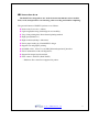
Introduction
The PORTI-S is designed for use with electronic instruments such as mobile
POS, retail, transportation. warehousing, other traveling and mobile computing.
The general features of PORTI-S printer are as follows:
X Pocket size(76.6 x 103 x 34mm)
X Light weight(S30:226g, S40:264g) for true mobility.
X Very silent printing thru direct thermal printing method.
X High speed(50mm/sec)
X High resolution(203dpi : 8dots/mm).
X Easier paper loading by CLAMSHELL design.
ٻ
X Support text and graphic printing.
X Serial(RS-232C) , IrDA Ver 1.0(SIR) [Bluetooth(optional)] interface
X Easier maintenance with self-diagnostics.
X Support bit-image(logo) download.
X Flow control : Software (XON/XOFF)
ଖ Hardware flow control not supported in printer.
ٻۈۊھډۈۄێۊۊےډےےےڊڊڕۋۏۏۃٻ
ڎ
Operating Precautions
Please follow the precautions below to enjoy and maintain the full
performance of the printer.
XUsing
the Printer
Ɣ
Be careful not to drop or bump the printer on a hard surface.
̻G
Do not install the printer in direct sunlight or such areas.
Suitable environment for the use of the printer is as follows :
ଝ Operating temperature : -10°C to 40°C
ଝ Relative humidity : 10% to 90% (no condensation)
̻G
Do not install the printer near devices that generate strong
electromagnetic fields such as a copy machine.
̻G
Do not remove or reinstall the communication cable during printing
or transmission.
ٻۈۊھډۈۄێۊۊےډےےےڊڊڕۋۏۏۃٻ
ڏ
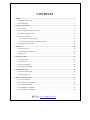
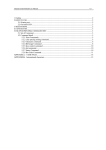
CONTENTS
1. Outline ............................................................................................................................................7G
1.1. Model classifications..............................................................................................................7G
1.2. Specifications .........................................................................................................................8G
2. Setting up the printer ....................................................................................................................9G
2.1. Unpacking ..............................................................................................................................9G
2.2. Outer appearances and part name.........................................................................................10G
2.3. Replacing the paper roll .......................................................................................................12G
2.4. Power connection .................................................................................................................14G
2.4.1. Specified power supply ...............................................................................................14G
2.4.2. Installation / Remove the battery pack........................................................................14G
2.5. Setting operation mode.........................................................................................................16G
3. Interface........................................................................................................................................19G
3.1. RS-232C serial .....................................................................................................................19G
3.2. Infrared bidirectional serial ..................................................................................................20G
3.3. Bluetooth ..............................................................................................................................21G
4. Using the printer ..........................................................................................................................22G
4.1. Control panel ........................................................................................................................22G
4.2. The self test ..........................................................................................................................23G
4.3. Driver installation.................................................................................................................24G
4.4. Bit-image download .............................................................................................................26G
5. Consumable Parts........................................................................................................................27G
5.1. Recommended paper ............................................................................................................27G
5.2. Printing position ...................................................................................................................28G
6. Print Control Function................................................................................................................29G
6.1. Print Commands...................................................................................................................31G
6.2. Line Spacing Commands......................................................................................................33G
6.3. Character Commands ...........................................................................................................34G
6.4. Panel Button Commands ......................................................................................................41G
6.5. Print Position Commands .....................................................................................................42G
ٻۈۊھډۈۄێۊۊےډےےےڊڊڕۋۏۏۃٻ
ڐ
6.6. Bit-Image Commands...........................................................................................................55G
6.7. Status Commands .................................................................................................................60G
6.8. Barcode Commands .............................................................................................................61G
6.9. Macro Function Commands .................................................................................................65G
6.10. Miscellaneous function commands ....................................................................................67G
6.11. Line & box commands .......................................................................................................71G
6.12. Black mark detection commands........................................................................................72G
7. Introduction of Protocol IrDA (or Bluetooth)...........................................................................73G
7.1. Frame Structure ....................................................................................................................73G
7.2. Process of Getting the Printer Status ....................................................................................74G
7.2.1. Frame Format..............................................................................................................74G
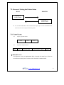
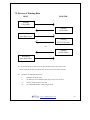
7.3. Process of Printing Data .......................................................................................................75G
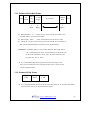
7.3.1. Format of Print Data Frame ........................................................................................76G
7.3.2. Format of ENQ Frame ................................................................................................76G
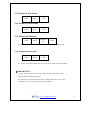
7.3.3. Format of ACK Frame ................................................................................................77G
7.3.4. Format of NACK Frame .............................................................................................77G
7.3.5. Format of ETX Frame.................................................................................................77G
7.3.6. Format of EOT Frame.................................................................................................77G
Appendix ..........................................................................................................................................78G
ٻۈۊھډۈۄێۊۊےډےےےڊڊڕۋۏۏۃٻ
ڑ
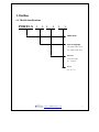
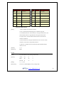
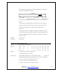
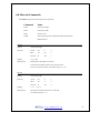
1. Outline
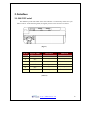
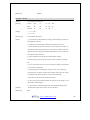
1.1. Model classifications
ٻ
PORTI–S (
) (
)
(
)
Model name
Size of roll paper
30: 57mm wide, 30 Ø
40: 57mm wide, 40 Ø
Interface
None:Serial/IrDA
BT : Bluetooth
Power
None : DC 7.4V
ٻۈۊھډۈۄێۊۊےډےےےڊڊڕۋۏۏۃٻ
ڒ
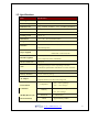
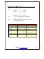
1.2. Specifications
Item
Specification
Printing method
Direct thermal line printing
Characters per line
42cpl
Character size
Eng. : 9*24dots, 12*24dots
Resolution
203dpi, 8dots/mm
Print width
2-inch (48mm, 384dots)
Printing speed
50mm / sec
Dimensions
76.6 * 103 * 34 mm (Standard model)
Weight
S30 : 226g, S40 : 264g (Including battery & roll paper)
Kor. : 16*24dots, [24*24dots]
Serial(RS-232C) , IrDA Ver1.0 (SIR) (Standard model),
Interface
Bluetooth(optional)
Thermal roll paper
PORTI-S30 : 57mm wide, 30ø
Paper supplied
PORTI-S40 : 57mm wide, 40ø
PDF417(2-dimension), Code128, Code39, I12 / 5, Code93
Barcode supplied
UPC, EAN( KAN, JAN), CODABAR
Receive buffer size
10K bytes
Printing speed may be slower, depending on the data
Note
transmission speed and the combination of control commands.
Battery
Rechargeable 7.4V DC , 1100mA (Li-ion)
Battery duration
1 hour continuous printing
Input (100~250V AC 50~60Hz)
AC adapter
Output(8.4VDC/0.8A), 4hours full charge time
-10°C ~ 40°C (operating)
Temperature
Environment
-10°C ~ 70°C (storage)
Conditions
30% - 80% (operating)
Humidity
10% - 90% (storage)
MCBF (Mean Cycle
Between failure)
Mechanical
Head
37,000,000 lines
Approximately 50 Km
ٻۈۊھډۈۄێۊۊےډےےےڊڊڕۋۏۏۃٻ
ړ
2. Setting up the printer
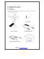
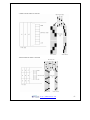
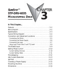
2.1. Unpacking
Your printer box should include these items. If any items are damaged or missing, please
contact your dealer for assistance.
G
G
PORTI-S
ROLL PAPER
G
Operator’s Manual
Communication Cable
ٻ
Adaptor for Battery Recharge
LEATHERETTE
ٻ
ٻۈۊھډۈۄێۊۊےډےےےڊڊڕۋۏۏۃٻ
ڔ
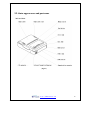
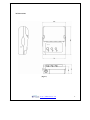
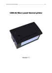
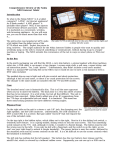
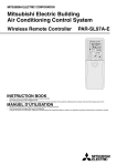
2.2. Outer appearances and part name
ඖ Part Name
(Fig.2.1)
ٻۈۊھډۈۄێۊۊےډےےےڊڊڕۋۏۏۃٻ
ڋڌ
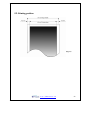
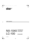
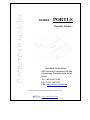
ඖ Dimensions
)(Fig.2.2
ڌڌ
ٻۈۊھډۈۄێۊۊےډےےےڊڊڕۋۏۏۃٻ
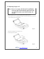
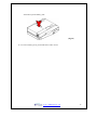
2.3. Replacing the paper roll
Note : Be sure to use paper rolls that meet the specifications.
Do not use paper rolls that have the paper glued to the
core because the printer cannot detect the paper end
correctly.
1. Make sure that the printer is not receiving data; otherwise, data may be lost.
2. Open the paper roll cover by applying your finger on both side of printer, push it up when the
lock is released as shown in the drawing.G
ٻ
ٻ
ٻ
ٻ
ٻ
ٻ
ٻ
ٻ
(Fig.2.3)
ٻ
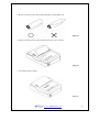
3. Remove the used paper roll core if there is one.
4. Insert the paper roll as shown.
ٻ
G
(Fig.2.4)
ٻۈۊھډۈۄێۊۊےډےےےڊڊڕۋۏۏۃٻ
ڍڌ
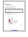
5. Be sure to not the correct direction that the paper comes off the roll.
(Fig.2.5)
6. Pull out a small amount of paper and then close the cover as shown.
G
(Fig.2.6)
7. Tear off the paper as shown.
G
(Fig.2.7)
ٻۈۊھډۈۄێۊۊےډےےےڊڊڕۋۏۏۃٻ
ڎڌ
2.4. Power connection
2.4.1. Specified power supply
The following specifications are requested for Power supply.
Vpp
: DC 7.4V Standby 60mA and Max 3A
2.4.2. Installation / Remove the battery pack
NOTE : ̻ Before installing or removing the battery pack, turn the printer power
off.
̻ If the printer is not used for a long time, remove the battery pack from
printer
ྙ To install battery pack, proceed as follows:
1) Installing the battery pack
- Insert the battery pack in the direction of the arrow at hole.
ٻ
(Fig.2.8)
ٻۈۊھډۈۄێۊۊےډےےےڊڊڕۋۏۏۃٻ
ڏڌ
- Push the top of the battery pack.
(Fig.2.9)
ྚ To remove battery pack, proceed the above order reverse.
ٻۈۊھډۈۄێۊۊےډےےےڊڊڕۋۏۏۃٻ
ڐڌ
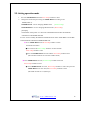
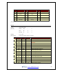
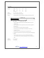
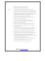
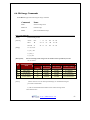
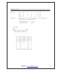
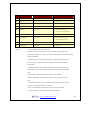
2.5. Setting operation mode
1.
Press the MODE Button until the Error Lamp twinkles 5 times
2.
Change the mode and option using the MODE Button according to the
MODE(Table 1).
z FEED Button : use for changing MODE status.
(Power Lamp)
z MODE Button : use for changing OPTION status. (Error Lamp)
[Example]
The defaults of the printer are : RS-232C/ 9600 BPS/8 DATA BIT/ NO PARITY
/ DENSITY LOW/MARK NOUSE
If a user wants to modify the defaults with PROTOCOL IrDA/ 38400 BPS/ 7 DATA BIT
/EVEN PARITY/ DENSITY HIGH/MARK USE
X Press MODE Button until Error Lamp twinkles 5 times
and release the button
o You will see the Power Lamp twinkles one time and the
Error Lamp twinkles 1 time
o Press the MODE Button one time and the Error Lamp twinkles twice
(The interface mode has set to Protocol IrDA mode)
X Press FEED Button one time, Power Lamp twinkles twice and
Error Lamp twinkles 4 times
o Press MODE Button one time, Error Lamp twinkles 5 times and press the
MODE Button one more time, the Error Lamp twinkles 6 times
(The baud rate has set to 38,400 bps)
ٻۈۊھډۈۄێۊۊےډےےےڊڊڕۋۏۏۃٻ
ڑڌ
X Press FEED Button one time, Power Lamp twinkles 3 times
and Error Lamp twinkles 2 times
o Press MODE Button one time, Error Lamp twinkles one time
(The Data Bit has set to 7 data bit)
X Press FEED Button one time, Power Lamp twinkles 4 times and
Error Lamp twinkles 1 time.
o Press MODE Button one time, Error Lamp twinkles 2 times
(The Parity bit has set to even parity bit)
X Press FEED Button one time, Power Lamp twinkles 5 times and
Error Lamp twinkles 1 time
o Press MODE Button one time, Error Lamp twinkles 2 times after then press
MODE Button again, the Error Lamp will twinkle 3 times
( The density has set to High)
X Press FEED Button one time, Power Lamp twinkles 7 times and
Error Lamp twinkles 1 time
o Press MODE Button one time, Error Lamp twinkles 2 times
( The mark has set to Use)
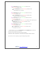
If all the mode have set, press the MODE Button and the FEED Button at the same time
after then release the buttons at the same time.
The printer will print out the mode status which has modified.
(PROTOCOL IrDA/ 38,400 BAUD/ 7 DATA BIT/ EVEN PARITY/ DENSITY HIGH)
If the status is not correct, please try it again according to the procedure.
ٻۈۊھډۈۄێۊۊےډےےےڊڊڕۋۏۏۃٻ
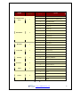
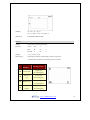
ڒڌ
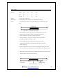
POWER Lamp
MODE Lamp
(Green)
(Red)
MODE
Communication
Option
1
Port
Baud Rate
Data Bit
Parity Bit
Density
Protocol
Mark
Sensor
2
3
4
5
6
7
8
1
RS-232C
2
Protocol IrDA (or Bluetooth)
3
Standard IrDA
1
1200 bps
2
2400 bps
3
4800 bps
4
9600 bps
5
19200 bps
6
38400 bps
7
57600 bps
8
9600 bps
1
7 Data bit
2
8 Data bit
1
No Parity
2
Even Parity
3
Odd Parity
1
Density Low
2
Density Medium
3
Density High
1
Default Protocol
2
Lotte Protocol
1
No use
2
Use
1
Low
2
Medium1
3
Medium2
4
High
(Table 1))
ٻۈۊھډۈۄێۊۊےډےےےڊڊڕۋۏۏۃٻ
ړڌ
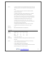
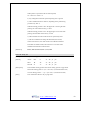
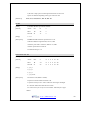
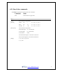
3. Interface
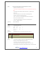
3.1. RS-232C serial
The PORTI-S printer has an RS-232C serial interface is connected by means of a 6 pin
male connector. In the following table, the signals present on the connector are listed:
(Fig.3.1)
Pin no
Signal Name
Direction
Function
1
GND
-
Ground
2
N.C
-
-
ٻ
3
N.C
-
-
ٻ
4
RxD
Input
Receive data
ٻ
5
N.C
-
-
ٻٻ
6
TxD
Output
Transmit data
ٻ
ٻ
ٻ
(Tab.3.1)
ٻ
ٻۈۊھډۈۄێۊۊےډےےےڊڊڕۋۏۏۃٻ
ڔڌ
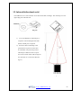
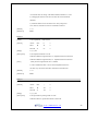
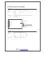
3.2. Infrared bidirectional serial
The PORTI-S has a serial interface for bi-directional data exchange. The infrared port is the
upper edge part of the left side.
(Fig.3.2)
1) To use the PORTI-S’s infrared port, a
computer or Personal Digital Assistant
(PDA) with IR port is required.
2) Position a PDA conforming to the
specifications in point not more than
50 centimeter away from the printer’s
infrared port. Make sure the two ports
are in front of each other with an angle of
not more than 15° on the four sides(see
fig.3.3)
(Fig.3.3)
ٻۈۊھډۈۄێۊۊےډےےےڊڊڕۋۏۏۃٻ
ڋڍ
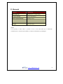
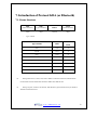
3.3. Bluetooth
Category
Specification
Bluetooth Spec.
Bluetooth V1.1 / Class2 (10m)
Frequency Range
2.4GHz ISM BAND
Data Transmission Rate
57600bps Fixed.
Data bit
8 Data bit Fixed.
Parity bit
No parity Fixed.
Stop bit
1 Stop bit Fixed.
Notice
If the quantity of data which is printed at once is more than 20K byte on Bluetooth
communication, it would cause the buffer to overflow and the data to get damaged.
ٻۈۊھډۈۄێۊۊےډےےےڊڊڕۋۏۏۃٻ
ڌڍ
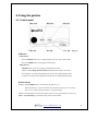
4. Using the printer
4.1. Control panel
ٻ
ٻ
ٻ
ٻ
ٻ
ٻ
ٻ
ٻ
ࢽ
ࢽ
ࢽ
(Fig.4.1)
X Button
- Feed button :
Press the FEED button once to advance paper one line. You can also hold
down the FEED button to feed paper continuously.
- Mode button :
MODE Button is for use to change communication mode.
(Refer to 2.5. Setting operation mode for details about mode conversion)
If you want to set to RS-232C Mode, just connect the communication cable
to connector of the printer and then the mode will be changed automatically.
X Panel lamp
-Power : The POWER lamp is on whenever the printer is on.
But when the battery is almost exhausted, this led flashes with red color occasionally.
In this case, you must recharge the battery by using the adapter.
-Error : This indicates an error such as paper end, or cover open, mode conversionGetc.
-Data : The Data lamp is on whenever the printer receives data.
ٻۈۊھډۈۄێۊۊےډےےےڊڊڕۋۏۏۃٻ
ڍڍ
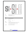
4.2. The self test
The self-test checks whether the printer has any problems. If the printer
does not function properly, contact your dealer. The self-test checks the following;
1. Make sure paper roll has been installed properly.
2. Turn on the power while holding down the FEED button. The self-test begins.
3. The self-test prints the current printer status, which provides the control ROM version and
the communication method setting.
4. After printing the current printer status, self-test printing will print a pattern using the builtin character set.
5. The self-test automatically ends
The printer is ready to receive data as soon as it completes the self-test.
G
ٻۈۊھډۈۄێۊۊےډےےےڊڊڕۋۏۏۃٻ
ڎڍ
4.3. Driver installation
ٻThe driver installation instruction were written for the printer to be used with the Infrared port
and serial port(RS-232C).
Make sure that your PC has built-in infrared device(IrDA Ver1.0).
Printer driver can download by Internet( http://www.woosim.com).
Installing the PORTI-S Printer Driver on Windows 98/ME/2000/XP.
1) You must install new driver after deleting old driver.
-
Delete the old driver
-
Reboot the computer
* If there is not any installed driver, you can install new driver immediately.
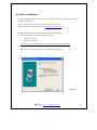
2) Run the setup.exe
Press the “Next” after checking the supported Operating System.
ٻ
(Fig.4.2)
ٻۈۊھډۈۄێۊۊےډےےےڊڊڕۋۏۏۃٻ
ڏڍ
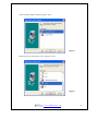
3) Select printer model to install, and press “Next”.
(Fig.4.3)
4) Select the port connected to printer, and press “Next”
(Fig.4.4)
ٻۈۊھډۈۄێۊۊےډےےےڊڊڕۋۏۏۃٻ
ڐڍ
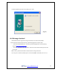
5) If the installation has done successfully, press “OK”.
(Fig.4.5)
4.4. Bit-image download
The PORTI-S Printer supports bit image download to the internal Flash ROM.
The bit image download require the Porti_Download application and PCX file.
-
Porti_Download Application : The Porti_Download application can download by
internet( http://www.woosim.com).
-
PCX file : The picture must be black or white PCX file and the width of picture must
be 8 pixel.
Refer to Porti_Download manual for details about bit-image download.
You can print out the downloaded picture with referred ESC f command. (See sec. 6.6)
ٻۈۊھډۈۄێۊۊےډےےےڊڊڕۋۏۏۃٻ
ڑڍ
5. Consumable Parts
5.1. Recommended paper
Type
: Thermal Paper
Paper width
: 57mm
Paper thickness
: 70±5 Mm
Outer diameter
: Ø30 or less (PORTI-S30), Ø40mm or less (PORTI-S40)
Recording side
: Outside of roll
Cautions
1. Do not paste the paper to the core. And the roll paper which has
near end mark printing on its near end is recommended.
2.
Chemicals or oil may change the color of paper, or printed
characters may fade.
3.
Change of paper color starts from approx. 70 C.
Pay attention to heat, humidity and sun light.
4.
Color of paper may be changed by being scratched by nail or hard metal, etc.
ٻۈۊھډۈۄێۊۊےډےےےڊڊڕۋۏۏۃٻ
ڒڍ
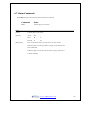
5.2. Printing position
)(Fig.5.1
ړڍ
ٻۈۊھډۈۄێۊۊےډےےےڊڊڕۋۏۏۃٻ
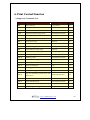
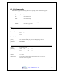
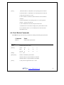
6. Print Control Function
Ɣ Supported Commands List
Command
Name
Function Type
Page
HT
Horizontal tab
Print position
45
LF
Print and line feed
Print
31
FF
Print and return to standard mode
Print
32
CAN
Cancel print data in page mode
Miscellaneous function
70
ESC FF
Print data in page mode
Print
32
ESC SP
Set right-side character spacing
Character
35
ESC !
Select print mode
Character
36
ESC $
Set absolute print position
Print position
42
ESC *
Select bit-image mode
Bit image
55
ESC -
Turn underline mode on/off
Character
37
ESC 2
Select default line spacing
Line spacing
33
ESC 3
Set line spacing
Line spacing
33
ESC @
Initialize printer
Miscellaneous function
68
ESC D
Set horizontal tab positions
Print position
46
ESC E
Turn emphasized mode on/off
Character
38
ESC J
Print and feed paper
Print
31
ESC L
Select page mode
Miscellaneous function
68
ESC O
Set print starting position.
Print position
54
Black mark detection
72
Set the movement position from the
ESC P
black mark
ESC R
Select an international character set
Character
35
ESC S
Select standard mode
Miscellaneous function
69
ESC T
Select print direction in page mode
Print position
51
ESC W
Set printing area in page mode
Print position
49
ٻۈۊھډۈۄێۊۊےډےےےڊڊڕۋۏۏۃٻ
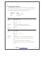
ڔڍ
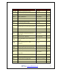
Command
Name
Function Type
Page
ESC X 4
Define user-defined bit-image
Bit image
58
ESC \
Set relative print position
Print position
43
ESC Z
Print 2D barcode
Barcode
64
ESC a
Select justification
Print position
44
ESC c 5
Enable/disable panel buttons
Panel button
41
ESC d
Print and feed n lines
Print
32
ESC f
Print downloaded bit image
Bit image
59
ESC v
Transmit paper sensor status
Status
60
Feed the paper to the movement position
Black mark detection
72
ESC {
Turn upside-down printing mode on/off
Character
38
GS !
Select characters size
Character
39
Print position
52
Macro function
65
Character
40
Barcode
64
ESC z
ESC y
Set absolute vertical print position in
GS $
GS :
page mode
Start/end macro definition
Turn white/black reverse printing mode
GS B
On/off
Select printing position of HRI
GS H
ٻ
characters
GS L
Set left margin
Print position
47
GS P
Set horizontal and vertical motion units
Miscellaneous function
68
GS W
Set printing area width
Print position
48
Print position
53
Set relative vertical print position in
GS \
page mode
GS ^
Execute macro
Macro function
66
GS h
Set barcode height
Barcode
61
GS i
Print box & line in page mode
Box & line command
71
GS k
Print bar code
Barcode
62
GS w
Set barcode width
Barcode
61
ٻۈۊھډۈۄێۊۊےډےےےڊڊڕۋۏۏۃٻ
ڋڎ
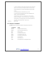
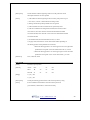
6.1. Print Commands
The PORTI-S supports the following commands for printing character and advancing paper:
Command
Name
LF
Print and line feed
ESC J
Print and feed paper
ESC d
Print and feed n lines
FF
Print and return to standard mode(in page mode)
ESC FF
Print data in page mode
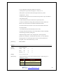
LF
[Name]
Print and line feed
[Format]
ASCII
LF
HEX
0A
Decimal
10
[Description]
Print the data in the print buffer and feeds one line based on the
current line spacing.
[Note]
This command sets the print position to the beginning of the line.
[Reference]
ESC 2, ESC 3
ESC J n
[Name]
Print and feed paper.
[Format]
ASCII
ESC
J
n
HEX
1B
4A
n
Decimal
27
74
n
[Range]
0 n 255
[Description]
Prints the data in the print buffer and feeds the paper [n x (vertical or
horizontal motion unit)] inches.
ٻۈۊھډۈۄێۊۊےډےےےڊڊڕۋۏۏۃٻ
ڌڎ
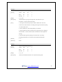
ESC d n
[Name]
Print and feed n lines
[Format]
ASCII
ESC
d
n
HEX
1B
64
n
Decimal
27
100
n
[Range]
0n
255
[Description]
Prints the data in the print buffer and feeds n lines.
[Note]
1) This command sets the print starting position to the beginning of the line.
2) This command does not affect the line spacing set by ESC 2 or ESC 3.
[Reference]
ESC 2, ESC 3
FF
[Name]
Print and return to standard mode in page mode.
[Format]
ASCII
FF
HEX
0C
Decimal
12
[Description]
Prints the data in the print buffer collectively and returns to standard mode.
[Note]
1) The buffer data is deleted after being printed.
2) The Printing area set by ESC W is reset to the default setting.
3) This command sets the print position to the beginning of the line.
4) This command is enabled only in page mode.
[Reference]
ESC FF, ESC L, ESC S
ESC FF
[Name]
Print data in page mode.
[Format]
ASCII
ESC
FF
HEX
1B
0C
Decimal
27
12
[Description]
In page mode, prints all buffered data in the printing area collectively.
[Note]
This commands is enabled only in page mode.
After printing the printer does not clear the buffered data, setting values for
ESC T and ESC W, and the position for buffering.
[Reference]
FF, ESC L, ESC S
ٻۈۊھډۈۄێۊۊےډےےےڊڊڕۋۏۏۃٻ
ڍڎ
6.2. Line Spacing Commands
The PORTI-S supports the following commands for setting line spacing.
These commands only set
the line spacing; they do not actually advance the paper. The line spacing set using these commands
affects the results of LF and ESC d and paper feeding by using the FEED button.
Command
Name
ESC 2
Select default line spacing
ESC 3
Set line spacing
ESC 2
[Name]
Select default line spacing
[Format]
ASCII
ESC
2
HEX
1B
32
Decimal
27
50
[Description]
Selects 1/7 inch line (approximately 3.75mm) spacing.
[Note]
The line spacing can be set independently in standard mode and
in page mode.
[Reference]
ESC 3
ESC 3 n
[Name]
Set line spacing
[Format]
ASCII
ESC
3
n
HEX
1B
33
n
Decimal
27
51
n
[Range]
0 n 255
[Description]
Sets the line spacing
[Note]
1) The line spacing can be set independently in standard mode and in page
to [n x vertical or horizontal motion until] inches.
mode.
2) The horizontal and vertical motion unit are specified by GS P.
Changing the horizontal or vertical motion unit does not affect the current line
spacing.
ٻۈۊھډۈۄێۊۊےډےےےڊڊڕۋۏۏۃٻ
ڎڎ
3) The GS P command can change the horizontal (and vertical) motion unit.
However, the value cannot be less than the minimum vertical movement
amount, and it must be in even units of the minimum vertical movement
amount.
4) In standard mode, the vertical motion unit (y) is used.
5) In page mode, this command functions as follows, depending on the
starting
position of the printable area:
When the starting position is set to the upper left or lower right of the
printable area using ESC T, the vertical motion unit(y) is used. When the
starting position is set to the upper right or lower left of the printable area
using ESC T, the horizontal motion
[Reference]
unit(x) is used.
ESC 2, GS P
6.3. Character Commands
The PORTI-S supports the following commands for setting character font and size:
Command
Name
ESC SP
Set right-side character spacing
ESC R
Select an international character set
ESC !
Select print mode
ESC -
Turn underline mode on/off
ESC E
Turn emphasized mode on/off
ESC G
Turn double-strike mode on/off
ESC {
Turn upside-down
GS !
Select character size
GS B
Turn white/black reverse printing mode on/off
ٻۈۊھډۈۄێۊۊےډےےےڊڊڕۋۏۏۃٻ
ڏڎ
ESC SP n
[Name]
Set right-side character spacing.
[Format]
ASCII
ESC
SP
n
HEX
1B
20
n
Decimal
27
32
n
[Range]
0 n 255
[Description]
Sets the character spacing for the right side of the character to [n x
horizontal or vertical motion units] inches.
[Note]
1) The right side character spacing for double-width mode is twice the
normal value. When characters are enlarged, the right side character spacing
is n times normal value.
2) This command sets values independently in each mode.
3) The horizontal and vertical motion unit are specified by GS P. Changing
the horizontal or vertical motion unit does not affect the current right-side
spacing.
4) The maximum right side spacing if 255/180 inches, Any setting
exceeding the maximum is converted to the maximum automatically.
[Default]
n=0
[Reference]
GS P
ESC R n
[Name]
Select an international character set.
[Format]
ASCII
ESC
R
n
HEX
1B
52
n
Decimal
27
82
n
[Range]
0 n 10
[Description]
Selects an international character set n from the following table.
ٻۈۊھډۈۄێۊۊےډےےےڊڊڕۋۏۏۃٻ
ڐڎ
n
Character set
n
Character set
n
Character set
0
U.S.A
5
Sweden
10
Denmark II
1
France
6
Italy
2
Germany
7
Spain
3
U.K
8
Japan
4
Denmark I
9
Norway
[Default] n = 0
ESC ! n
[Name]
Select print mode.
[Format]
ASCII
ESC
!
n
HEX
1B
21
n
Decimal
27
33
n
[Range]
0 n 255
[Description]
Select print mode(s) using n as follows.
Bit
0
1
2
3
4
5
6
7
Off / On
Hex
Decimal
Function
Off
00
0
Character font A (12 x 24)
On
01
1
Character font B (9 x 24)
Off
-
-
Undefined
On
-
-
Undefined
Off
-
-
Undefined
On
-
-
Undefined
Off
00
On
08
Off
00
On
10
Off
00
On
20
32
Off
-
-
Undefined
On
-
-
Undefined
Off
00
0
Underline mode not selected
On
80
128
Emphasized mode not selected
8
Emphasized mode selected
Double-height mode not selected
16
Double-height mode selected
Double-width mode not selected
Double-width mode selected
Underline mode selected
ٻۈۊھډۈۄێۊۊےډےےےڊڊڕۋۏۏۃٻ
ڑڎ
[Note]
1) When both double-height and double-width modes are selected,
quadruple size characters are printed.
2) The printer can underline all characters, but can not underline the space set by
HT.
3) The thickness of the underline is that selected by ESC -, regardless of the
character size.
4) When some characters in a line are double or mode height, all the
characters on the line are aligned at the baseline.
5) ESC – can also turn on or off underline mode. However, the setting of
the last received command is effective.
7) GS ! can also select character size. However, the setting of the last
received
[Reference]
command is effective.
ESC -, ESC E, GS!
ESC - n
[Name]
Turn underline mode on/off
[Format]
ASCII
ESC
-
n
HEX
1B
2D
n
Decimal
27
45
n
[Range]
0n1
[Description]
Turns underline mode on or off, based on the following values of n;
n
Function
0, 48
Turns off underline mode
1. 49
Turns on underline mode (1 dot thick).
2, 50
Turns on underline mode (2 dot thick)
[Notes]
1) The printer can underline all characters (including right-side character
spacing), but cannot underline the space set by HT.
2) The printer cannot underline white/black inverted characters.
3) When underline mode id turned off by setting the value of n to 0 or 48,
the following data is not underlined, and the underline thickness set before the mode
ٻۈۊھډۈۄێۊۊےډےےےڊڊڕۋۏۏۃٻ
ڒڎ
is turned off does not change. The default underline thickness is 1 dot.
4) Changing the character size does not affect the current underline
thickness.
5) Underline mode can also be turned on or off by using ESC !.
Note, however, that the last received command is effective.
[Default]
n=0
[Reference]
ESC !
ESC E n
[Name]
Turn emphasized
mode On/Off.
[Format]
ASCII
ESC
E
n
HEX
1B
45
n
Decimal
27
69
n
[Range]
0 n 255
[Description]
Turns emphasized mode on of off.
When the LSB(least significant bit) is 0, emphasized mode is turned off.
When the LSB(least significant bit) is 1, emphasized mode is turned on.
[Note]
1) Only the least significant bit of n is enabled.
2) This command and ESC ! turn on and off emphasized mode in
the same way. Be careful when this command is used with ESC !
[Default]
n=0
[Reference]
ESC !
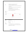
ESC { n
[Name]
Turn On/Off upside-down printing mode
[Format]
ASCII
ESC
{
n
HEX
1B
7B
n
Decimal
27
123
n
[Range]
0 n 255
[Description]
Turns upside-down printing mode on of off
When the LSB is 0, upside-down mode is turned off.
ٻۈۊھډۈۄێۊۊےډےےےڊڊڕۋۏۏۃٻ
ړڎ
When the LSB is 1, upside-down mode is turned on.
[Note]
1) Only the lowest significant bit of n is valid.
2) This command is enabled only when processed at the beginning of a line
in standard mode.
3) When this command is input in page mode, the printer performs only
internal flag operations.
4) This command does not affect printing in page mode.
5) In upside-down printing mode, the printer rotates the line to be
printed by 180 degree and then prints it.
[Default] n = 0
[Example]
GS ! n
[Name]
Select character size
[Format]
ASCII
GS
!
n
HEX
1D
21
n
Decimal
29
33
n
[Range]
0 n 255
[Description]
(1 vertical number of times 8, 1 horizontal number of times
8) Selects the character width using bits 0 to 2 and selects the character
height using bits 4 to 7, as follows;
ٻۈۊھډۈۄێۊۊےډےےےڊڊڕۋۏۏۃٻ
ڔڎ
Hex
Decimal
Width
Hex
Decimal
Height
00
0
1 (normal)
00
0
1 (normal)
01
1
2 (double width)
10
16
2 (double height)
02
2
3
20
32
3
03
3
4
30
48
4
04
4
5
40
64
5
05
5
6
50
80
6
06
6
7
60
96
7
07
7
8
70
112
8
Character Height Selection
Character Width Selection
[Notes]
1) This command is all characters effective
2) If n is outside of the defined range, this command is ignored.
3) In standard mode, the vertical direction is the paper feed direction, and
the horizontal direction is perpendicular to the paper feed direction.
4) In page mode, vertical and horizontal directions are based on the
character orientation.
5) When characters are enlarged with different sizes on one line, all the
characters on the line are aligned at the baseline.
6) The ESC ! command can also turn double width and double height
modes on or off.
[Default]
n=0
[Reference]
ESC !
GS B n
[Name]
Turn white/black reverse printing mode On/Off.
[Format]
ASCII
GS
B
n
HEX
1D
42
n
Decimal
29
66
n
[Range]
0 n 255
[Description]
Turns on or off White/Black reverse printing mode.
ٻۈۊھډۈۄێۊۊےډےےےڊڊڕۋۏۏۃٻ
ڋڏ
[Notes]
1) When the LSB is 0, white/black reverse printing mode is turned on.
2) When the LSB is 1, white/black reverse printing mode is turned off.
3) Only the lowest bit of n is valid.
4) This command is available for built in characters and user defined
characters.
5) When white/black reverse printing mode is on, it also applied to
character spacing set by ESC SP.
6) This command does not affect the space between lines.
7) White/black reverse mode has a higher priority than underline mode.
Even if underline mode is on, it is disabled (but not canceled) when
white/black reverse
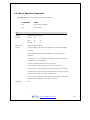
6.4. Panel Button Commands
The PORTI-S supports the following command for enabling and disabling the panel button.
Command
Name
ESC c 5
Enable/disable panel buttons
ESC c 5 n
[Name]
Enable/Disable panel buttons
[Format]
ASCII
ESC
c
5
n
HEX
1B
63
35
n
Decimal
27
97
53
n
[Range]
0n
255
[Description]
Enables or disables the panel buttons.
When the LSB is 0, the panel buttons are enabled.
When the LSB is 1, the panel buttons are disabled.
[Notes]
1) Only the least significant bit of n is valid.
ٻۈۊھډۈۄێۊۊےډےےےڊڊڕۋۏۏۃٻ
ڌڏ
2) When the panel buttons are disabled, none of them are usable when the
printer cover is closed.
3) In this printer, the panel buttons is the FEED button.
4) In the macro ready mode, the FEED button are enabled regardless of the
settings of this command; however, the paper cannot be fed by using
these buttons.
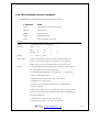
6.5. Print Position Commands
The PORTI-S supports the following commands for setting the print position
Command
Name
ESC $
Set absolute print position
ESC \
Set relative print position
ESC a
Select justification
HT
Horizontal tab
ESC D
Set horizontal tab positions
GS L
Set left margin
GS W
Set printing area width
ESC W
Set printing area in page mode
ESC T
Select print direction in page mode
GS $
Set absolute vertical print position in page mode
GS \
Set relative vertical print position in page mode
ESC O
Set print starting position.
ESC $ nL nH
[Name]
Set absolute print position
[Format]
ASCII
ESC
$
nL
nH
HEX
1B
24
nL
nH
Decimal
27
36
nL
nH
[Range]
0 nL 255
ٻۈۊھډۈۄێۊۊےډےےےڊڊڕۋۏۏۃٻ
ڍڏ
[Description]
Set the distance from the beginning of the line to the position at which
subsequent characters are to be printed.
[Notes]
1) The distance from the beginning of the line to the print position is [(nL
+ nH x 256) x (vertical or horizontal motion unit)] inches.
2) Setting outside the specified printable area are ignored.
3) The horizontal and vertical motion unit are specified by GS P.
4) The GS P command can change the horizontal (and vertical) motion
unit. However, the value cannot be less than the minimum horizontal
movement amount, and it must be in even units of he minimum horizontal
movement amount.
5) In standard mode, the horizontal motion unit (x) is used.
6) In page mode, horizontal or vertical motion unit differs depending on
the starting position of the printable area as follows;
1. When the starting position is set to the upper left or lower right of the
printable area using ESC T, the horizontal motion unit (x) is used.
2. When the starting position is set to the upper right or lower left of the
printable area using ESC T, the vertical motion unit (y) is used.
[Reference]
ESC\, GS$, GS\, GS P
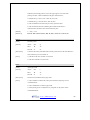
ESC \ nL nH
[Name]
Set relative print position
[Format]
ASCII
ESC
\
nL
nH
HEX
1B
5C
nL
nH
Decimal
27
92
nL
nH
[Range]
0 nL 255,
0 nL 255
[Description]
[Notes]
Set the print starting position based on the current position by using
1) This command sets the distance from the current position to
[(nL+nHx256) x horizontal or vertical motion unit]
ٻۈۊھډۈۄێۊۊےډےےےڊڊڕۋۏۏۃٻ
ڎڏ
2) Any setting that exceeds the printable are is ignored
3) When pitch N is specified to the right; nL + nH x 256 = N
When pitch N is specified to the left (the negative direction), use the
complement of 65536.
4) The print starting position moves from the current position to [N x horizontal or
vertical motion unit)]
5) The horizontal and vertical motion unit are specified by GS P.
6) The GS P command can change the horizontal (and vertical) motion unit.
However, the value cannot be less than the minimum horizontal
movement amount, and it must be in even units of the minimum horizontal
movement amount.
7) In standard mode, the horizontal motion unit is used.
8) In page mode, the horizontal or vertical unit differs as follows, depending
on the starting point of the printing area;
When the starting position is set to the upper left or lower right of the
printable area using ESC T, the horizontal motion unit (x) is used. When the
starting position is set to the upper right or lower left of the printable area
using ESC T, the vertical motion unit (y) is used.
[Reference]
ESC $, ESC P
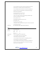
ESC a n
[Name]
Select justification
[Format]
ASCII
ESC
a
n
HEX
1B
61
n
Decimal
27
97
n
[Range]
0 n 2 , 48 n 50
[Description]
Aligns all the data in one line to the specified position. n selects the type of
justification as follows;
n
Justification
0, 48
Left justification
1, 49
Center justification
2, 50
Right justification
ٻۈۊھډۈۄێۊۊےډےےےڊڊڕۋۏۏۃٻ
ڏڏ
[Notes]
1) The command is enabled only when processed at the beginning of the
line in standard mode.
2) If this command is input in page mode, the printer performs only internal flag
operations.
3) This command has no effect in page mode.
4) This command executes justification in the printing area.
5) This command justifies the space area according to HT, ESC $ or ESC \
[Default]
n=0
[Example]
HT
[Name]
Horizontal Tab
[Format]
ASCII
HT
HEX
09
Decimal
9
[Description]
Moves the print position to the next horizontal tab position.
[Note]
1) This command is ignored unless the next horizontal tab position has been
set.
2) If the next horizontal tab position exceeds the printing area, the printer
sets the printing position to [Printing area width + 1]
3) Horizontal tab positions are set with ESC D.
4) If this command is received when the printing position is at [Printing
area width + 1], the printer executes print buffer-full printing of the current
line and horizontal tab processing from the beginning of the next line.
5) The default setting of the horizontal tab position for the paper roll is every 0th
character.
ٻۈۊھډۈۄێۊۊےډےےےڊڊڕۋۏۏۃٻ
ڐڏ
[Reference]
ESC D
ESC D n1…nk NUL
[Name]
Set horizontal tab positions.
[Format]
ASCII
ESC
D
n1…nk
NUL
HEX
1B
44
n1…nk
00
Decimal
27
68
n1…nk
0
[Range]
1 <= n <= 255
0 <= k <=32
[Description]
Set horizontal tab position
[Notes]
1) n specifies the column number for setting a horizontal tab position from
the beginning of the line.
2) k indicates the total number of horizontal tab positions to be set.
3) The horizontal tab position is stored as a value of [character width x n]
measured from the beginning of the line. The character width includes the
right-side character spacing, and double-width characters are set with twice
the width of normal characters.
4) This command cancels the previous horizontal tab settings.
5) When setting n=8, the print position is moved to column 9 by sending
HT.
6) Up to 32 tab positions (k=32) can be set. Data exceeding 32 tab positions
is processed as normal data.
7) Transmit [n]k in ascending order and place a NUL code 0 at the end.
8) When [n]k is less than or equal to the preceding value [n]k-1, tab setting
is finished and the following data is processed as normal data.
9) ESC D NUL cancels all horizontal tab positions.
10) The previously specified horizontal tab positions do not change, even if
the character width changes.
11) The character width is memorized for each standard and page mode.
[Default]
The default tab positions are at intervals of 0 characters.
[Reference]
HT
ٻۈۊھډۈۄێۊۊےډےےےڊڊڕۋۏۏۃٻ
ڑڏ
GS L nL nH
[Name]
Set left margin.
[Format]
ASCII
GS
L
nL
nH
HEX
1D
4C
nL
nH
Decimal
29
76
nL
nH
[Range]
0 nL 255, 0 nH 255
[Description]
Set the left margin using nL and nH.
[Notes]
1)The left margin is set to [(nL+nHx256)] x (horizontal motion unit) inches.
2) This command is effective only processed at the beginning of the line in
standard mode.
3) If this command is input in page mode, the printer performs only internal
flag operations.
4) This command does not affect printing in page mode.
5) If the setting exceeds the printable area, the maximum value of the
printable area is used.
6) The horizontal and vertical motion units are specified by GS P.
Changing the horizontal and vertical motion unit does not affect the current left
margin.
7) The horizontal motion unit (x) is used for calculating the left margin.
The calculated result is truncated to the minimum value of the mechanical
pitch.
[Default]
nL = 0, nH = 0
[Reference]
GS P, GS W
ٻۈۊھډۈۄێۊۊےډےےےڊڊڕۋۏۏۃٻ
ڒڏ
GS W nL nH
[Name]
Set printing area width
[Format]
ASCII
GS
W
nL
nH
HEX
1D
57
nL
nH
Decimal
29
87
nL
nH
[Range]
0 nL 255, 0 nH 255
[Description]
Sets the printing area width to the area specified by nL and nH.
[Notes]
1) The printing area width is set to [(nL+nHx256)] x horizontal motion unit
inches.
2) This command is effective only processed at the beginning of the line.
3) In page mode, the printer performs only internal flag operations.
4) This command does not affect printing in page mode.
5) If the [left margin + printing area width] exceeds the printable area,
(printable area width - left margin) is used.
6) The horizontal and vertical motion units are specified by GS P.
Changing the horizontal and vertical motion units does not affect the
current left margin.
7) The horizontal motion unit (x) is used for calculating the printing area width.
The calculated result is truncated to the minimum value of the mechanical pitch.
8) If the width set for the printing area is less than the width of one character, when
the character data is developed, the following
ٻۈۊھډۈۄێۊۊےډےےےڊڊڕۋۏۏۃٻ
ړڏ
If the printing area width cannot be extended sufficiently, the left margin is
reduced to accommodate one character.
If the printing area width cannot be extended sufficiently, the right space is
reduced.
9) If the width set for the printing area is less than one line in vertical, the
following processing is performed only on the line in question when data
other than character data(e.g., bit image, user defined bit image) is
developed:
The printing area width is extended to the right to accommodate one line in
vertical for the bit image within the printable area. If the printing area width
cannot be extended sufficiently, the left margin is reduced to accommodate
one line in vertical.
[Default]
nL = 0, nH = 2
[Reference]
GS L, GS P
ESC W xL xH yL yH dxL dxH dyL dyH
[Name]
Set printing area in page mode
[Format]
ASCII
ESC
W
xL
xH yL yH dxL
dxH dyL
dyH
HEX
1B
57
xL
xH yL yH dxL
dxH dyL
dyH
Decimal
27
87
xL xH yL yH dxL dxH dyL dyH
[Range]
0 xL,xH,yL,yH,dxL,dxH,dyL,dyH 255
(except dxL=dxH=0 or dyL=dyH=0)
[Description]
The horizontal starting position, vertical starting position,
printing area
width, and printing area height are defined as x0, y0, dx(inch), respectively.
x0 = [(xL + xH * 256)] * (horizontal motion unit)
y0 = [(yL +yH * 256)] * (vertical motion unit)
dx = [(dxL + dxH x 256)] x (horizontal motion unit)
ٻۈۊھډۈۄێۊۊےډےےےڊڊڕۋۏۏۃٻ
ڔڏ
dy = [(dyL + dyH * 256)] * (vertical motion unit)
The printing area is set as shown in the figure below.
[Note]
1) If this commands is input in standard mode, the printer executes only
internal flag operation. This command does not affect printing in standard mode.
2) If the horizontal or vertical starting position is set outside the printable area, the
printer stops command processing and processes the following data as normal data.
3) If the printing area width or height is set to 0, the printer stops command
processing and processes the following data as normal data.
4) This command sets the position where data is buffered to the position
specified by ESC T within the printing area.
5) If (horizontal starting position + printing area width) exceeds the
printable area, the printing area width is automatically set to (horizontal
printable area - horizontal starting position).
6) If (vertical starting position + printing area height) exceeds the printable
area, the
printing area height is automatically set to (vertical printable area-
vertical starting position).
7) The horizontal and vertical motion unit are specified by GS P. Changing
the horizontal or vertical motion unit does not affect the current printing area.
8) The GS P command can change the horizontal (and vertical) motion unit.
However, the value cannot be less than the minimum horizontal movement
amount, and it must be in even units of minimum horizontal movement amount.
9) Use the horizontal motion unit (x) for setting the horizontal starting
position and printing area width, and use the vertical motion unit (y) for setting the
vertical starting position and printing area height.
10) When the horizontal starting position, vertical starting position, printing
area
width, and printing area height are defined as X, Y, Dx, Dy
respectively, the printing area is set as shown in the figure below.
ٻۈۊھډۈۄێۊۊےډےےےڊڊڕۋۏۏۃٻ
ڋڐ
[Default]
xL = xH = yL = yH = 0
dxL = 0, dxH = 2, dyL = 126, dyH = 6
[Reference]
CAN, ESC L, ESC T, GS P
ESC T n
[Name]
Select print direction in page mode
[Format]
ASCII
ESC
T
n
HEX
1B
54
n
Decimal
27
84
n
[Range]
0 n 3 or 48 n 51
[Description]
Selects the print direction and starting position in page mode.
n specifies the print direction and starting position as follows;
n
Print
Starting position
direction
0,48
1,49
2,50
3,51
Left to right
Upper left
(A in the figure)
Bottom to
Lower left
top
(B in the figure)
Right to left
Lower right
(C in the figure)
Top to
Upper right
bottom
(D in the figure)
ٻۈۊھډۈۄێۊۊےډےےےڊڊڕۋۏۏۃٻ
ڌڐ
[Notes]
1) When the command is input in standard mode, the printer executes only
internal flag operation. This command does not affect printing in standard
mode.
2) This command sets the position where data is buffered within the
printing area set by ESC W.
3) Parameters for horizontal or vertical motion units (X or Y) differ as
follows, depending on the starting position of the printing area;
If the starting position is the upper left or lower right of the printing area,
data is buffered in the direction perpendicular to the paper feed direction.
Commands using horizontal motion unit: ESC SP, ESC $, ESC \
Commands using vertical motion unit: ESC 3, ESC J, GS $, GS \
If the starting position is the upper right or lower left of the printing area,
data is buffered in the paper feed direction.
Commands using horizontal motion units : ESC 3, ESC J, GS $,GS \
Commands using vertical motion units : ESC SP, ESC $, ESC \
[Default]
n=0
[Reference]
ESC $, ESC L, ESC W, ESC \, GS $, GS P, GS \
GS $ nL nH
[Name]
Set absolute vertical print position in page mode.
[Format]
ASCII
GS
$
nL
nH
HEX
1D
24
nL
nH
Decimal
29
36
nL
nH
[Range]
0 nL 255, 0 nH 255
[Description]
Sets the absolute vertical print starting position for buffer character data in
page mode.
[Notes]
1) This command sets the absolute print position to [(nL+nHx256)]x
(vertical or horizontal motion unit) inches.
2) This command is effective only in page mode.
3) If the [(nL+nHx256)] x (vertical or horizontal motion unit) exceeds the
specified printing area, this command is ignored.
ٻۈۊھډۈۄێۊۊےډےےےڊڊڕۋۏۏۃٻ
ڍڐ
4) The horizontal starting buffer position does not move.
5) The reference starting position is that specified by ESC T.
6) This command operates as follows, depending on the starting position of
the printing area specified by ESC T; When the starting position is set to the
upper left or lower right, this command sets the absolute position in the
vertical direction. When the starting position is set to the upper right or
lower left, this command sets the absolute position in the horizontal
direction.
7) The horizontal and vertical motion unit are specified by GS P.
8) The GS P command can change the horizontal and vertical motion unit.
However, the value cannot be less than the minimum horizontal movement
amount, and it must be in even units of the minimum horizontal movement
amount.
[Reference]
ESC $, ESC T, ESC W, ESC \, GS P, GS \
GS \ nL nH
[Name]
Set relative vertical print position in page mode
[Format]
ASCII
GS
\
nL
nH
HEX
1D
5C
nL
nH
Decimal
29
92
nL
nH
[Range]
0 nL 255
0 nH 255
[Description]
Sets the relative vertical print starting position from the current position in
page mode.
[Notes]
1) This command sets the distance from the current position to [(nL +
nHx256)] x vertical or horizontal motion unit inches.
2) This command is ignored unless page mode is selected.
3) When pitch N is specified to the movement downward;
nL + nHx256 = N When pitch N is specified to the movement upward (the
negative direction), use the complement of 65536.
ٻۈۊھډۈۄێۊۊےډےےےڊڊڕۋۏۏۃٻ
ڎڐ
ٻ
ٻ
When pitch N is specified to the movement upward;
nL + nH x 256 = 65536 - Nٻ
4) Any setting that exceeds the specified printing area is ignored.
5) This command function as follows, depending on the print starting
position set by ESC T;
When the starting position is set to the upper left or lower right of the
printing, the vertical motion unit (y) is used.
When the starting position is set to the upper right or lower left of the
printing, the horizontal motion unit (x) is used.
6) The horizontal and vertical motion unit are specified by GS P.
7) The GS P command can change the horizontal (and vertical)
motion unit. However, the value cannot be less than the minimum
horizontal movement amount, and it must be in even units of the
minimum horizontal movement amount.
[Reference]
ESC $, ESC T, ESC W, ESC \, GS $, GS P
ESC O xL xH yL yH
[Name]
Set print starting position.
[Format]
ASCII
ESC
O
xL xH yL yH
HEX
1B
4F
xL xH yL yH
Decimal
27
79
xL xH yL yH
[Description]
Set horizontal starting position and vertical starting position in page mode.
Horizontal starting position = (xL + xH * 256) * (horizontal motion unit)
Vertical starting position
[Note]
= (yL + yH * 256) * (vertical motion unit)
This command is effective only in page mode.
ٻۈۊھډۈۄێۊۊےډےےےڊڊڕۋۏۏۃٻ
ڏڐ
6.6. Bit-Image Commands
The PORTI-S supports the following bit-image command.
Command
Name
ESC *
Select bit image mode
ESC X 4
Print bit image
ESC f
print downloaded bit image
ESC * m nL nH d1 dk
[Name]
Select bit-image mode.
[Format]
ASCII
ESC
*
m
nL
nH
d1…dk
HEX
1B
2A m
nL
nH
d1…dk
Decimal
27
42 m
nL
nH
d1…dk
[Range]
m = 0,1,32,33
0 nL 255
0 nH 3
0 d 255
[Description]
Selects a bit-image mode using m for the number of dots specified by nL and
nH, as follows:
m
mode
0
1
32
33
8 dot single
8 dot double
24 dot single
24 dot double
[Notes]
Vertical direction
Number
Dot density
of Dots
8
60 DPI
8
60 DPI
24
180DPI
24
180 DPI
Horizontal direction
Dot density
Number of Data
90 DPI
180 DPI
90 DPI
180 DPI
nL+nHx256
nL+nHx256
(nL+nHx256)x3
(nL+nHx256)x3
1) If the values of m is out of the specified range, nL and data following are
processed an normal data.
2) The nL and nH indicate the number of dots of the bit image in the
horizontal direction.
ٻۈۊھډۈۄێۊۊےډےےےڊڊڕۋۏۏۃٻ
ڐڐ
ٻ
3) The number of dots is calculated by nL + nH x 256.
4) If the bit-image data input exceeds the number of dots to be printed on a
line, the excess data is ignored.
5) d indicates the bit-image data. Set a corresponding bit to 1 to print a dot
or to 0 to not print a dot.
6) If the width of the printing area set by GS L and GS W less than the
width required by the data sent with the ESC * command, the following will
be performed on the line in question (but the printing cannot exceed the maximum
printable area):
The width of the printing area is extended to the right to accommodate the amount
of data.
If step does not provide sufficient width for the data, the left margin is
reduced to accommodate the data.
7) After printing a bit image, the printer returns to normal data processing
mode.
8) This command is not affected by print modes (emphasized, doublestrike, underline, character size or White/Black reverse printing), except
upside-down printing mode.
9) The relationship between the image data and the dots to be printed is as
follows;
ٻۈۊھډۈۄێۊۊےډےےےڊڊڕۋۏۏۃٻ
ڑڐ
- When 8-dot bit image is selected
- When
24-dot bit image is selected
ٻۈۊھډۈۄێۊۊےډےےےڊڊڕۋۏۏۃٻ
ڒڐ
ESC X 4 x y d1…dk
[Name]
Print bit-image.
[Format]
ASCII
ESC
X
4
x y
d1…dk
HEX
1B
58
34
x y
d1…dk
Decimal
27
88
52
x y
d1…dk
[Description]
ESC X 4 x y d1 ... d(x y)
ҏ print bit image using x ҏ8 dots in the horizontal
direction and y dots in the vertical direction.
- Horizontal direction dots
- Vertical direction dots
= (x * 8)dots
=
(y)dots
ٻۈۊھډۈۄێۊۊےډےےےڊڊڕۋۏۏۃٻ
ړڐ
[Note]
ESC X 4 is supported in Porti_W,S produced after August,2002, but it’s not
supported in others yet.
[Reference]
ESC L, ESC W, ESC O, ESC FF
ESC f n
[Name]
Print downloaded bit-image.
[Format]
ASCII
ESC
f
n
HEX
1B
66
n
Decimal
27
102
n
[Range]
n = 0, 1, 48, 49
[Description]
ESC f prints a downloaded bit image specified by n as follows:
prints a downloaded bit image1 when n = 0 or n = 48,
prints a downloaded bit image2 when n = 1 or n = 31.
[Reference]
ESC L, ESC W, ESC O, ESC FF
ٻۈۊھډۈۄێۊۊےډےےےڊڊڕۋۏۏۃٻ
ڔڐ
6.7. Status Commands
The PORTI-S supports the following status transmission command.
Command
Name
ESC v
Transmit paper sensor status
ESC v
[Name]
Transmit paper sensor status
[Format]
ASCII
ESC
v
HEX
1B
76
Decimal
27
118
[Description]
ESC v transmits the status of a paper sensor as 1byte of data.
When the paper roll end sensor detects a paper, printer transmits the
NULL(H00) data.
When the paper roll end sensor doesn’t detect a paper, printer don’t
Transmit anything.
ٻۈۊھډۈۄێۊۊےډےےےڊڊڕۋۏۏۃٻ
ڋڑ
6.8. Barcode Commands
The PORTI-S supports the following barcode commands.
Command
Name
GS h
Set barcode height
GS w
Set barcode width
GS k
Print bar code
GS H
Select printing position of Human Readable Interpretation
(HRI) characters
GS h n
[Name]
Set barcode height
[Format]
ASCII
GS
h
n
HEX
1D
68
n
Decimal
29
104
n
[Range]
0 n 255
[Description]
GS h n selects the height of a barcode.
n specifies the number of dots in the vertical direction.
One dot corresponds 1/8mm. The default setting is n = 80.
GS w n
[Name]
Set barcode width
[Format]
ASCII
GS
w
n
HEX
1D
77
n
Decimal
29
119
n
3n5
[Range]
n = 0,
[Description]
GS w n selects the horizontal size of a barcode.
The default setting is n = 0.
ٻۈۊھډۈۄێۊۊےډےےےڊڊڕۋۏۏۃٻ
ڌڑ
ཛGS k m d1…dk NUL
ཛྷGS k m n d1…dn
[Name]
Print barcode
[Format]
ཛASCII GS
HEX
1D
Decimal 29
ཛྷ ASCII GS
HEX
1D
Decimal 29
k
m d1…dk NUL
6B
m d1…dk 00
107
m d1…dk 0
k
m n d1…dn
6B
m n d1…dn
107
m n d1…dn
ཛ 0 m 6 (k and d depends on the bar code system used.)
[Range]
ཛྷ 0 m 6 (n and d depends on the bar code system used.)
[Description]
GS k m d1…dk NUL selects a barcode system and print the barcode.
m specifies a bar code system as follows;
ཛ
m
Barcode System
Number of character
Remarks
0
UPC-A
11 k 12
48 d 57
1
UPC-E
11 k 12
48 d 57
2
EAN13
11 k 13
48 d 57
3
EAN8
7k8
48 d 57
4
CODE39
1k
48 d 57, 65 d 90,
d = 32, 36, 37, 43, 45, 46,47
5
ITF
1 k (even number)
48 d 57
6
CODABAR
1k
48 d 57, 65 d 68,
d = 36, 43, 45, 46, 47, 58
ٻۈۊھډۈۄێۊۊےډےےےڊڊڕۋۏۏۃٻ
ڍڑ
ཛྷ
m
Barcode System
Number of characters
Remarks
65
UPC-A
11 n 12
48 d 57
66
UPC-E
11 n 12
48 d 57
67
EAN13
11 n 13
48 d 57
68
EAN8
7n8
48 d 57
69
CODE39
1 n 255
48 d 57, 65 d 90,
d = 32, 36, 37, 43, 45, 46,47
70
ITF
1 n 255 (even number)
48 d 57
71
CODABAR
1 n 255
48 d 57, 65 d 68,
d = 36, 43, 45, 46, 47, 58
72
CODE93
1 n 255
0 d 127
73
CODE128
2 n 255
0 d 127
[Notes]
1) This command ends with a NUL code.
2) When the bar code system used is UPC-A or UPC-E, the printer prints
the bar code data after receiving 12 bytes bar code data and processes the following
data as normal data.
3) When the bar code system used in EAN13, the printer prints the bar code
after receiving 13 bytes bar code data and processes the following data as
normal data.
4) When the bar code system used in EAN8, the printer prints the bar code
after receiving 8 bytes bar code data and processes following data as normal
data.
5) The number of data for ITF bar code must be even numbers.
When an odd number of data is input, the printer ignores the last received
data.
6) n indicates the number of bar code data, and the printer processes n bytes
from the next character data as bar code data.
7) If n is outside of the specified range, the printer stops command
processing and processes the following data as normal data.
ٻۈۊھډۈۄێۊۊےډےےےڊڊڕۋۏۏۃٻ
ڎڑ
8) Be sure to keep spaces on both right and left sides of a bar code.
Spaces are different depending on the types of the bar code.
[Reference]
GS h, GS w, GS H, ESC L, ESC W, ESC FF
GS H n
[Name]
Turn HRI characters print mode ON/OFF
[Format]
ASCII
GS
H
n
HEX
1D
48
n
Decimal
29
72
n
[Range]
n = 0, 1
[Description]
GS H n turns HRI characters print mode on or off.
When the LSB(least significant bit) of n is 1, HRI
characters print mode is turned on; When it is 0, HRI
character print mode is turned off.
The default setting is n=0.
ESC Z m n k d d1…dn
[Name]
Print 2D barcode
[Format]
ASCII
ESC
Z
m n k d d1…dn
HEX
1B
5A
m n k d d1…dn
Decimal
27
90
m n k d d1…dn
[Range]
1m7
0n8
2k5
1 d 65535
[Description]
Print 2D bar code (PDF417 format).
m specifies column number of 2D bar code.
n specifies security level to restore when bar code image is damaged.
k is used for define horizontal and vertical ratio.
d is consist of 2 byte. 1st byte is lower number. And 2nd byte is upper
number.
ٻۈۊھډۈۄێۊۊےډےےےڊڊڕۋۏۏۃٻ
ڏڑ
6.9. Macro Function Commands
The PORTI-S supports the following macro function commands;
Command
Name
GS :
Start/end macro definition
GS ^
Execute macro
GS :
[Name]
Start/End macro definition
[Format]
ASCII
GS
:
HEX
1D
3A
Decimal
29
58
[Description]
Starts ends macro definition.
[Notes]
1) Macro definition starts when this command is received during normal
operation.
Macro definition ends when this command is received during macro
definition.
2) When GS ^ is received during macro definition, the printer ends macro
definition and clears the definition.
3) Macro is not defined when the power is turned on.
4) The defined contents of the macro are not cleared by ESC @.
Therefore, ESC @ can be included in the contents of the macro definition.
5) If the printer receives GS : again immediately after previously receiving
GS : the printer remains in the macro undefined state.
6) The contents of the macro can be defined up to 2048 bytes. If the macro
definition exceed 2048 bytes, excess data is not stored.
[Reference]
GS ^
ٻۈۊھډۈۄێۊۊےډےےےڊڊڕۋۏۏۃٻ
ڐڑ
GS ^ r t m
[Name]
Execute macro.
[Format]
ASCII
GS
^
r t m
HEX
1D
5E
r t m
Decimal
29
94
r t m
[Range]
0 <= r <= 255
0 <= t <= 255
m = 0, 1
[Description]
Executes a macro.
[Notes]
1) r specifies the number of times to execute the macro.
2) t specifies the waiting time for executing the macro.
3) m specifies macro executing mode.
When LSB of m = 0
The macro executes r times continuously at the interval specified by t.
When LSB of m = 1 After waiting for the period specified by t, the ERROR
LED indicators blink and the printer waits for the FEED button to be
pressed. After the button is pressed, the printer executes the macro once.
The printer repeats the operation r times.
4) The waiting time is t x 100 ms for every macro execution.
5) If this command is received while a macro is being defined, the macro
definition is aborted and the definition is cleared.
6) If the macro is not defined or if is 0, nothing is executed.
7) When the macro is executed (m=1), paper always cannot be fed by using
the FEED button.
[Reference]
GS :
ٻۈۊھډۈۄێۊۊےډےےےڊڊڕۋۏۏۃٻ
ڑڑ
6.10. Miscellaneous function commands
The PORTI-S supports the following miscellaneous function commands;
Command
Name
GS P
Set horizontal and vertical motion units
ESC @
Initialize printer
ESC L
Select page mode
ESC S
Select standard mode
CAN
Cancel print data in page mode
GS P x y
[Name]
Set horizontal and vertical motion units.
[Format]
ASCII
GS
P
x
y
HEX
1D
50
x
y
Decimal
29
80
x
y
[Range]
0 x 255, 0 y 255
[Description]
Sets the horizontal and vertical motion units to approximately 25.4/x
mm(1/x inch) and approximately 25.4/y mm(1/y inch), respectively.
When x and y are set to 0, the default setting of each value is used.
[Notes]
1) The horizontal direction is perpendicular to the paper feed direction and
the vertical direction is the paper feed direction.
2) In standard mode, the following commands use x or y, regardless of
character rotation (upside-down).
Command using x : ESC SP, ESC $, ESC \, GS L, GS W
Command using y : ESC 3, ESC J
3) In page mode, the following command use x or y, depending on
character orientation;
When the print starting position is set to the upper left or lower right of the
printing area using ESC T(data is buffered in the direction perpendicular to
the paper feed direction);
Command using x : ESC SP, ESC $, ESC W, ESC \
Command using y : ESC 3, ESC J, ESC W, GS $, GS \
ٻۈۊھډۈۄێۊۊےډےےےڊڊڕۋۏۏۃٻ
ڒڑ
When the print starting position is set to the upper right or lower left of the
printing area ESC T (data is buffered in the paper feed direction);
Command using x : ESC 3, ESC J, ESC W, GS $, GS \
Command using y : ESC SP, ESC $, ESC W, ESC \
4) The command does not affect the previously specified values.
5) The calculated result from combining this command with others is
truncated to the minimum value of the mechanical pitch.
[Default]
x = 180, y = 360
[Reference]
ESC SP, ESC $, ESC 3, ESC J, ESC W, ESC \, GS $, GS L, GS W, GS \
ESC @
[Name]
Initialize printer.
[Format]
ASCII
ESC
@
HEX
1B
40
Decimal
27
64
[Description]
Clears the data in the print buffer and resets the printer mode to the mode that was n
effect when the power was turned on.
[Notes]
1) The data in the receive buffer is not cleared.
2) The macro definition is not cleared.
ESC L
[Name]
Select page mode
[Format]
ASCII
ESC
L
HEX
1B
4C
Decimal
27
76
[Description]
Switches from standard mode to page mode.
[Notes]
1) This command is enabled only when processed at the beginning of a line
in standard mode.
2) This command has no effect in page mode.
3) After printing by FF is completed or by using ESC S, the printer returns
to standard mode.
ٻۈۊھډۈۄێۊۊےډےےےڊڊڕۋۏۏۃٻ
ړڑ
4) This command sets the position where data is buffered to the position
specified by ESC T within the printing area defined by ESC W.
5) This command switches the settings for the following commands (in
which the values can be set independently in standard mode and page
mode) to those for page mode;
Set right-side character spacing : ESC SP
Select default line spacing : ESC 2, ESC 3
6) Only valve settings is possible for the following commands in page
mode; these commands are not executed.
Select justification : ESC a
Turn upside-down printing mode on/off : ESC {
Set left margin : GS L
Set printable area width : GS W
7) The printer returns to standard mode when power is turned on, the printer
is reset, or ESC @ is used.
[Reference]
FF, CAN, ESC FF, ESC S, ESC T, ESC W, GS $, GS \
ESC S
[Name]
Select standard mode
[Format]
ASCII
ESC
S
HEX
1B
53
Decimal
27
83
[Description]
Switches from page mode to standard mode.
[Note]
1) This command is effective only in page mode.
2) Data buffered in page mode are cleared.
3) This command sets the print position to the beginning of the line.
4) The printing area set by ESC W are initialized.
5) This command switches the settings for the following commands (in
which the values can be set independently in standard mode and page
mode) to those for standard mode;
ٻۈۊھډۈۄێۊۊےډےےےڊڊڕۋۏۏۃٻ
ڔڑ
Set right-side character spacing : ESC SP
Select default line spacing : ESC 2, ESC 3
6) The following commands are enabled only to set in standard mode.
Set printing area in page mode : ESC W
Select print direction in page mode : ESC T
7) The following commands are ignored in standard mode.
Set absolute vertical print position in page mode : GS $
Set relative vertical print position in page mode : GS \
8) Standard mode is selected automatically when power is turned on,
the printer is reset, or command ESC @ is used.
[Reference]
FF, ESC FF, ESC L
CAN
[Name]
Cancel print data in page mode
[Format]
ASCII
CAN
HEX
18
Decimal
24
[Description]
In page mode, deletes all the print in the current printable area.
[Notes]
This command is enable only in page mode.
If data that existed in the previously specified printing area also exists in
The currently specified printing area, it is deleted.
[Reference]
ESC L, ESC W
ٻۈۊھډۈۄێۊۊےډےےےڊڊڕۋۏۏۃٻ
ڋڒ
6.11. Line & box commands
The PORTI- S supports the following line & box commands;
Command
Name
GS i
Print line & box in page mode
GS i
[Name]
Print line & box in page mode
[Format]
ASCII
GS
i
xL
HEX
1D
69
xL xH yL yH n
Decimal
29
105
xL xH yL yH n
[Description]
xH yL yH n
Print line & box in page mode
Horizontal length
: xL + xH *256(dot)
Vertical length
: yL+ yH*256(dot)
Line thickness
: n (dot)
If the horizontal length is 0, it becomes vertical line
If the vertical length is 0, it becomes horizontal line
[Range]
0 xL, xH, yL, yH 255
0 n 255
ٻۈۊھډۈۄێۊۊےډےےےڊڊڕۋۏۏۃٻ
ڌڒ
6.12. Black mark detection commands.
ESC P xL xH
[Name]
Set the movement position from the black mark.
[Format]
ASCII
ESC
P
HEX
1B
50
Decimal
[Description]
27
xL
xH
80
The movement position will be set when this command is sent to the
printer just once.
G
iGG
G
G
m
sGRG oGQGY\]GOGPG
tGwG
ESC z ESC y
[Name]
Feed the paper to the movement position.
[Format]
ASCII
ESC
z
ESC
y
HEX
1B
7A
1B
79
122
27
121
Decimal
[Description]
27
Feed the paper to the movement position.
ٻۈۊھډۈۄێۊۊےډےےےڊڊڕۋۏۏۃٻ
ڍڒ
7. Introduction of Protocol IrDA (or Bluetooth)
7.1. Frame Structure
S OF
(Start Of Frame)
TOF
(Type Of Frame)
DATA
EOF
(End Of Frame)
1 Byte
1 Byte
Variable
1 Byte
-
Type of frame
DATA
Type of frame
Value
ACK
0x06
X
NACK
0x15
X
ENQ
0x05
X
PRINT Data
‘D’ (0x44)
O
Response of Printer Status
‘S’ (0x53)
O
Inquiry of Printer Status
‘Q’ (0x51)
X
EOT
0x04
X
ETX
0x03
X
Field
During transmission, if C0H, C1H, and/or 7DH are contained in data field, 7DH should be
inserted before the data and the data should be XORed with 20H and sent.
During reception, if 7DH is encountered, 7DH should be ignored and the next byte should be
XORed with 20H and stored.
ٻۈۊھډۈۄێۊۊےډےےےڊڊڕۋۏۏۃٻ
ڎڒ
7.2. Process of Getting the Printer Status
HOST
PRINTER
Inquiry of
Printer Status
Response of
Printer Status
It is recommended that the host send the same inquiry up to 5 times with 400ms time
interval in case of no response from the printer.
7.2.1. Frame Format
Inquiry of printer status
0xC0
0xC0
0x51
0xC1
Response of printer status
0x53
Status (1 Byte)
Previous ID # (1 Byte)
0xC1
ଗ IMPORTANT !!
This function is not yet implemented fully. Currently the status byte is fixed to
0x02. However, this process can be used to check the communication.
ٻۈۊھډۈۄێۊۊےډےےےڊڊڕۋۏۏۃٻ
ڏڒ
7.3. Process of Printing Data
HOST
PRINTER
Sending
ENQ frame
Sending
ACK frame
Sending
Print Data frame
Sending
EOT, ETX frame
Or
Sending
NACK frame
Resending
Print Data frame
In normal operation, after receiving the print data frame, the printer sends
EOT, prints out the data, and sends ETX. And it will wait for the next frame.
Conditions of NACK frame issued
1)
Different checksum value
2)
No data byte received 200ms after the previous byte received
3)
No EOF (End of frame) at the end
4)
No predefined number in Data Length field
ٻۈۊھډۈۄێۊۊےډےےےڊڊڕۋۏۏۃٻ
ڐڒ
7.3.1. Format of Print Data Frame
C0H
'D'
(0x44)
DATA
ID
Number
1
Byte
kh{h
Print DATA
Length
kG
4
Bytes
CHECK
SUM
C1H
2
Bytes
Data ID number : ‘0’૫‘9’(0x30~0x39). Every time the host sends a new
print data frame, it increases this number.
Data Length : “0001” ૫ “9999”. Each number must be an ascii code.
Checksum : 2 bytes. The first byte is the result of XOR of even number of
data in Print data field and the second byte is that of odd number.
(Example) If “SAMPLE TEST” is in Print Data field, the data length will be
“0011 (0x30 0x30 0x31 0x31)” and the first byte of checksum will
be the result of XOR of S, M, L, space, E, and T and the second
byte that of A, P, E, T, and S.
It is recommended that the host goes back to the initial stage in case
that it receives neither EOT nor NACK from the printer 1 sec after it has
sent the print data frame.
7.3.2. Format of ENQ Frame
C0H
0x05
C1H
It is recommended that the host send the same ENQ frame up to 10 times with 400ms
time interval in case of no response from the printer.
ٻۈۊھډۈۄێۊۊےډےےےڊڊڕۋۏۏۃٻ
ڑڒ
7.3.3. Format of ACK Frame
C0H
0x06
C1H
7.3.4. Format of NACK Frame
C0H
0x15
C1H
7.3.5. Format of ETX Frame
C0H
0x03
Data ID
No.
C1H
Printer will send this frame after it finishes all of the requested printing.
7.3.6. Format of EOT Frame
C0H
0x04
C1H
Printer will send this frame after it receives the print data frame successfully.
ଗ IMPORTANT !!
In every frame coming from the printer, 1 Byte of Null is preceded to SOF,
and CR and LF are followed by EOF.
For example, the actual data of ETX frame is 0x00, 0xC0, 0x03, 0xC1, 0x0D,
and 0x0A. The host can ignore these prefix and suffixes.
ٻۈۊھډۈۄێۊۊےډےےےڊڊڕۋۏۏۃٻ
ڒڒ
Appendix
A. MISCELLANEOUS NOTES
1. Printer mechanism handling
1) Do not pull the paper out when the cover is closed.
2) Because the thermal elements of the print head and driver ICs are easy to break, so do not
touch them with any metal objects.
3) Since the areas around the print head become very hot during and just after printing, do not
touch them.
4) Do not use the cover open button except when necessary.
5) Do not touch the surface of the print head because bust and dirt can stick to the surface and
damage the elements.
6) Thermal paper containing Na, K, Cl ions can harm the print head thermal elements.
Therefore, be sure to use only the specified paper.
7) If you want to use label paper, please contact your dealer for assistance.
2. Thermal paper handling
- Notes on using thermal paper
Chemicals and oil on thermal paper may cause discoloration and faded printing.
Therefore, pay attention to the following;
1) Use water paste, starch paste, polyvinyl paste, or CMC paste when gluing thermal paper.
2) Volatile organic solvents such as alcohol, ester, and ketone can cause discoloration.
3) Some adhesive tapes may cause discoloration or faded printing.
4) If thermal paper touches anything which includes phthalic acid ester plasticizer for a long
time, it can reduce the image formation ability of the paper and can cause the printed image to
fade. Therefore, when storing thermal paper in a card case or sample notebook, be sure to use
only products made from polyethylene, polypropylene, or polyester.
5) If thermal paper touches diazo copy paper immediately after copying, the printed surface
may be discolored.
6) Thermal paper must not be stored with the printed surfaces against each
other because the printing may be transferred between the surfaces.
ٻۈۊھډۈۄێۊۊےډےےےڊڊڕۋۏۏۃٻ
ړڒ
7) If the surface of thermal paper is scratched with a hard metal object such as a nail,
the paper may become discolored.
- Notes on thermal paper storage
Since color development begins at 70¶C (158¶F), thermal paper should be protected
from high temperature, humidity, and light, both before and after printing.
1) Store paper away from high temperature and humidity.
Do not store thermal paper near a heater or in enclosed places exposed to direct sunlight.
2) Avoid direct light Extended exposure to direct light may cause discoloration or faded
printing.
3. Others
Because this printer uses plated steel, the manual cutting edge may be subject to rust.
However, this does not affect the printer performance.
ٻ
ٻۈۊھډۈۄێۊۊےډےےےڊڊڕۋۏۏۃٻ
ڔڒ