1
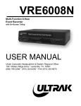
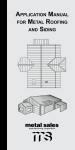
SLM446 System Quick Start Guide
Prior to connecting and operating the SLM446 Surveillance System, please read this quick start guide
carefully. Refer to the individual user’s manual included with the DVR for detailed operation.
Camera Setup and Connection
1) Remove all individual components and accessories from their packaging.
2) Using the included mounting hardware, install each of the cameras as desired. The (8) cameras supplied
are weatherproof and may be used indoor or out. Do NOT submerge these cameras. Be aware of any
existing utilities lines (electric, gas, water, etc) in the camera mounting area. Placed the cameras under an
eave or other protective area when mounting outdoors.
3) To connect the cameras to the DVR:
• Connect the video/power cable (supplied) to each camera. The BNC connection will supply
video to the DVR, the DC plug will supply power to the camera.
• Connect the BNC plug on the other end of the video/power cable to one of the video inputs on
the DVR.
• Connect the 2.1mm power jack and power supply as shown in the diagram. Do not attempt to power
other accessories or equipment not included in this system. If accessory items are added to the
system, use the power adapters that came with the accessory.
• Repeat for all cameras.
4) Connect the VIDEO OUT or the VGA video terminal on the DVR to the appropriate video in connection on
your monitor or TV.
5) Connect power to the DVR with the power supply as shown in the diagram.
6) Set up the DVR operation menu according to desired recording requirements.
THE MANUFACTURER DOES NOT ASSUME LIABILITY FOR ANY VIOLATION OF PRIVACY FROM ILLEGAL RECORDINGS OR MONITORING
MADE ON OR FROM THIS UNIT. THE USER/OWNER ASSUMES FULL LIABILITY FOR ANY AND ALL RECORDINGS MADE FROM THIS UNIT
IN A SECURITY OR SURVEILLANCE OPERATION OR IN ANY OTHER USE. THE MANUFACTURER IS NOT RESPONSIBLE FOR
RECORDINGS THAT VIOLATE LAWS OR THAT MAY PROVE OFFENSIVE OR TEND TO INCRIMINATE ANOTHER INDIVIDUAL. LOCAL, STATE,
AND FEDERAL LAWS MUST BE OBSERVED REGARDING ALL RECORDINGS.
Security Labs Customer Support Hotline
1-800-774-0284
15540 Herriman Blvd. Noblesville, IN 46060 www.security-labs.com
SLM446 System Connection Diagram
SLC-1056 Cameras
4x
CAMERA VIDEO OUT
Monitor or TV (not included)
12VDC POWER
NOTE: Use the DVR VIDEO OUT -or- the VGA VIDEO OUT for a
connection to the monitor. Do not use them simultaneously
To: PWR SUPPLY
Camera
power breakout
adapter (below)
VIDEO
IN
SLC-1054 Cameras
VIDEO
(VGA) IN
CAMERA VIDEO OUT
4x
VIDEO
FROM
DVR
(VIDEO
OUT)
12VDC POWER
To: PWR SUPPLY
Camera
power breakout
adapter (below)
VIDEO
FROM
DVR
(VGA)
TO BROAD BAND ROUTER CONNECTION
NOTE:
Cameras can connect to any open video
input on the DVR
DVR BACK PANEL
DVR
12VDC IN
AC PLUG
POWER SUPPLY
AC PLUG
Connect 12VDC plugs to
(4) SLC-1056 bullet camera
cable power jacks
POWER SUPPLY
CAMERAS ONLY
Connect 12VDC plugs to
(4) SLC-1054 dome camera
cable power jacks
(one plug will not be used)
DO NOT USE THE POWER SUPPLY TO POWER EQUIPMENT NOT INCLUDED IN SYSTEM