1
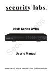
16 Channel Multiplexed
Digital Video Recorder
Owner’s Manual
Customer Support 1-800-774-0284
15540 Herriman Blvd. Noblesville, IN 46060
Safety Precautions
CAUTION
RISK OF ELECTRICAL
SHOCK. DO NOT OPEN !
CAUTION: TO REDUCE THE RISK OF ELECTRICAL SHOCK,
DO NOT REMOVE COVER (OR BACK), NO USER
SERVICEABLE PARTS REFER SERVICING TO
QUALIFIED SERVICE PERSONNEL.
A lightning flash with an arrowhead symbol, within an equilateral
triangle, is intended to alert the user to the presence of insulated
dangerous Voltage within the product’s enclosure that may be of
sufficient magnitude to constitute a risk of electrical shock.
An exclamation point within an equilateral triangle is intended to alert
the user of important operation and maintenance (servicing)
instructions in the literature accompanying the appliance..
WARNING: TO PREVENT FIRE OR SHOCK HAZARD, DO NOT
EXPOSE UNIT TO RAIN OR MOISTURE. THIS UNIT IS NOT
DESIGNED FOR OUTDOOR USE.
Attention: Installation should be performed by qualified service
personnel only in accordance with the National Electrical Code or
applicable local codes.
Power Disconnect. Units with or without ON-OFF switches have
power supplied to the unit whenever the power cord is inserted into
the power source; however, the unit is operational only when the
ON-OFF switch is the ON position. The power cord is the main power
disconnect for all units.
There are no serviceable parts inside this unit, call the manufacturer
Warranty
for details.
and Service
2
About this document
Before installing the DVR, be sure to thoroughly review and follow the instructions in this
User’s Manual. Pay particular attention to the parts that are marked NOTICE.
Also, when connecting with an external device, first turn the power OFF and follow the
manual’s instructions for a proper installation.
Please read all instructions before setting up the DVR
1. This document is intended for both the administrator and users.
2. This manual contains information for configuring, managing and using your DVR.
3. To prevent fire or electrical shock, do not expose this product to heat or moisture.
4. For questions and technical assistance of this product, contact our technical support at
800-774-0284.
Strong recommendations on installation of the DVR:
1. Ensure that the electricity at the place you want to install the DVR is stable and meets
electrical requirements.
2 Unit generates heat which must be properly discharged. Do not place objects beside
exhaust port(fan) on the left and the right side of the unit..
3. Place your DVR unit in a well-ventilated area. Do not place heat-generating objects on
top of the unit.
3
FCC Statement:
WARNING
This device complies with Part 15 of the FCC Rules. Operation is subject to the following
two conditions: (1) This device may not cause harmful interference. (2) This device must
accept any interference received including interference that may cause undesired
operation.
* Federal Communications Commission (FCC) Statement
WARNING
This Equipment has been tested and found to comply with the limits for a Class B digital
device, pursuant to Part 15 of the FCC rules. These limits are designed to provide
reasonable protection against harmful interference in a residential installation. This
equipment generates, uses and can radiate radio frequency energy and, if not installed
and used in accordance with the instructions, may cause harmful interference to radio
communications. However, there is no guarantee that interference will not occur in a
particular installation. If this equipment does cause harmful interference to radio or
television reception, which can be determined by turning the equipment off and on, the
user is encouraged to try to correct the interference by one or more of the following
measures:
- Reorient or relocate the receiving antenna.
- Increase the separation between the equipment and receiver.
- Connect the equipment into an outlet on a circuit different from
that to which the receiver is connected.
- Consult the dealer or an experienced radio/TV technician for help.
* You are cautioned that changes or modifications not expressly approved by the party
responsible for compliance could void your authority to operate the equipment.
4
FRONT PANEL
1.
2.
/
/
: Split screen mode select button
Number button 0 ~ 9 : Channel 1 ~ 16 full screen select button
Channel 1 ~ 9, press 0 + 1 ~ 0 + 9
Channel 10 ~ 16, press 1 + 0 ~ 1 + 6
3.
AUTO
: Auto sequence mode
4.
LOCK
: Press this button to operate Key Lock function
5.
PTZ
: To PTZ control mode
6.
AUDIO
: Audio on or off select button
7.
BACKUP
: Image backup button
8.
UP / STOP
: Direction button UP / Playback stop button
9.
DOWN / PAUSE
: Direction button down / Playback pause
10.
REW / LEFT
: Reverse playback choose button / play speed
/
11.
FF / RIGHT
: Forward playback choose button / play speed
/
/
/
12. ENTER
: Enter button or value change(+)
13.
MENU
: Press this button to display the menu setup
14.
ESC
: Press this button to exit menu
15.
T-SRH
: Press this button to playback time search
16.
PLAY
: Press this button to playback
17.
+
: Increase + value.
18.
REC
: Press this button to start recording
19.
-
: Reduce - value
20.
USB 2.0
: Thumb Drive slot
(Step play)
*User should plug in USB again if ActiveX is loaded, image is backed up, or version is
updated.
5
REAR PANEL
Power code in 12V/5A, power switcher (ON / OFF)
Camera 1 ~ 16 input BNC type
Call / Main Monitor out
VGA out
Audio channel input x 4 and output x 2(left and right)
Alarm / Relay / RS 485 connector
RJ-45 (Network connector)
PS2 type mouse connector
RS232/ISP: Not available
6
DVR Initialing
or detecting a new hard disk
Recording icon
Overwrite
Motion
Alarm
Video loss
Keypad lock * 111111 is the default password
7
Live screen
Event (Motion / Alarm)
Mouse Control
1
Screen display
1. Double-click on the left button of desired camera
to display full screen
2. Double-click on the left button of desired camera
to view quad screen
3
Menu display
1. One-click right button to view menu OSD
2. Back to last OSD page
2
None
No function
1
Select
Selects Item to be viewed or changed
Operate:
MENU BUTTON
: Press MENU button to enter menu setup or exit
ESC
: Press ESC button to exit menu
ENTER BUTTON
: Press Enter button to confirm set or value change(+)
DIRECTION BUTTON : MENU item select
+ BUTTON
: Increase + value
- BUTTON
: Reduce - value
BACKUP
: To backup mode
PTZ
: To PTZ control mode
(
) MOVE
(ENT) SELECT
(MENU) EXIT
8
Remote control:
The keys on the remote control function the same as the front keypad of the unit.
Channel select 1 ~ 16 camera
Quad / Split screen
Auto:
Channel sequence
Audio
: Audio on / off
Note: See what is on remote now
UP / STOP : Direction button UP / Playback stop button
REW
: Reverse playback choose button
DOWN / PAUSE : Direction button down / Playback pause
FF
: Forward playback choose button
ENTER
: Enter button or value change
MENU
: Press this button to display the menu setup
BKUP
: Image backup button
ESC
: Press this button to exit menu
T-SRH
: Press this button to playback time search
PLAY
: Press this button to playback
REC
: Press this button to start recording
+ BUTTON
: Increase + value
- BUTTON
: Reduce - value
9
Main MENU – Camera Set
Main MENU – Camera Set – Title
Camera title setup function allows 5 characters for each channel.
10
Main Menu – Record Set
Record Set – Record Framerate
Record Set – Record Quality: High / Normal / Low
Record Set – Event Rec Duration: 5 / 10 / 15 / 20 / 25 / 30
Record Set – Auto Record: After 1 ~ 8 minutes, auto start to record if no operation.
Record Set - Data Retention Set: 1 ~ 15 days
Record Set – Schedule Record
Record Set – Schedule Record
11
Record Set – Schedule Record
Note: Hours of the day are displayed in Military
(24 Hour) time format.
Example:
0
0
= Midnight to 1:00 am
0
2
= 2:00 am – 3:00 am
0
4 = 4:00 am – 5:00 am
1
6 = 4pm – 5:00 pm etc.
The empty spaces in between are the odd
numbered hours of the day.
Notice:
1. Each channel has its own frame rate adjustment for each recording mode.
2. You can adjust each channel frame rate of different record modes, such as schedule, motion
detection, and alarm record mode.
3. Press
button to change to different record modes.
1. Schedule record mode
2. Motion record mode
12
3. Alarm record mode
4. Schedule, motion, and alarm record mode
Record Time Table: 250GB HD
Record Quality: Low. Average: 5 KB;
REC FPS
60
30
15
10
REC Hour
237.6
488.4
976.8
1465.2
Record Quality: Normal. Average 10 KB;
REC FPS
60
30
15
10
REC Hour
118.8
244.2
488.4
732.6
Record Quality: High. Average 20 KB;
REC FPS
60
30
15
10
REC Hour
59.4
122.1
244.2
366.3
This table is only for reference. Frame rate will vary slightly with the complexity of the images
being recorded.
20 K x 30 (frame rate) x 60 (mins) x 60 (secs) = 2160000 K = 2160 M / hr
2160 M / hr x 24 = 51840000 K = 51840 M = 51.84 G / (1 Day)
13
Please format hard disk before starting recording after all the HDD installation
Hard disk compatible table
IDE
Seagate
Hitachi
WD(AAJB)
Status
80 ~ 750 GB OK
80 ~ 750 GB OK
80 ~ 750 GB OK
Main Menu – Alarm Detection 1 ~ 16
Alarm Signal type depends on Alarm Sensor polarity defined as NO (N/Open) or NC (N/Close)
mode. Alarm POP UP: Event channel jumps to full screen when alarm is triggered. Quad
screen with the alarm symbol will display if more than two cameras are triggered.
14
Door closed
Door open
Relay: NO + COM or NC + COM
Relay action:
Relay: NO (Normal open)
NO
Alarm trigger
COM
Relay: NC (Normal Close)
NC
Main Menu – Motion Detection 1 ~ 16
15
COM
Main Menu – Motion Detection – Motion Area
cursor
Detected area
Motion POP UP: Motion channel jumps to full screen
when motion is triggered. 16 split screen with an alarm
symbol is displayed if more than two cameras are
triggered.
Main Menu – Motion Detection – Motion area selection
Direction button Left or Right + ENTER to cancel detection area.
Select start (right-up corner) point and end (left-below corner) point of detect area.
Start
End
One-click of the mouse left button will cancel detected area.
Select start (right-up corner) point and end (left-below corner) point of detection area.
Main Menu – Screen – Border: Quad border On / Off display
16
Main Menu – Screen – Video Adjustment: Video screen position movement
Main Menu – Screen – VGA Frequency and VGA
After selecting, press ENTER to see the changed resolution. Press ENTER to change, press
ESC to cancel. If no change is made, the mode will change back to the last status after 15
seconds.
DVR needs to reboot if 1280x1024 resolution is adjusted.
Main Menu – Audio Set
17
- To record audio, set to “on”. Adjust input/output levels for desired sound.
- Mute turns off live audio.
Main Menu – System Set – Hard Disk
Main Menu – System Set – Format HDD
Main Menu – System Set – Hard Disk Setup – Format HDD – Password
18
HDD was formatted successfully.
-The correct password needs to be entered before formatting the hard disk. The password is
the same as the default unlock password, which is 111111.
- Please set HDD to Master if only one is installed. Second HDD, if used, should be set to
Slave.
Main Menu – System Set – Security Protection - Password Change
19
Menu Protection:
On / Off. If set to “on”, you need to enter your password to access the menu.
Auto Key Lock:
After 1 ~ 120 seconds the system automatically goes into key lock mode. You will have to
“unlock” before operating the DVR..
Main Menu – System Set – Time Set
Select your time zone and auto time synchronization with an NTP server. An internet
connection is required for the NTP server. The NTP server does not work under network
DHCP mode. After time set or daylight mode turns to on, you need to Apply and confirm. 0 ~ 9
is repeatable with increase + button,
and decrease - button. If the DVR is connected to a network system, enable NTP server to get
20
a network request automatically.
System Set – Dwell Time Setup
(Full screen Channel auto sequence)
Main Menu – System Set – Network Settings
Network Settings – Local IP
Network Settings – Local IP – STATIC
Network Settings – Local IP – DHCP
Select static IP address / Gateway / Net Mask
Auto IP detected under IP sharing or router
21
Main Menu – System Set – Network – PPPOE
Main Menu – System Set – Network – PPPOE – ID
22
If the DVR is connected to the internet, enable Main Menu – System Set – Time Set NTP
server to get a network time request automatically.
Main Menu – System Set – Network – PPPOE – Password
Input PPPoE account and password, then save & exit menu.
IP will not correctly appear on screen if your firewall or router settings block communications
with your DVR.
Type the IP into Net viewer or IE browser to view image via network.
Main Menu – System Set – Network – D/DNS set
23
A Static IP Address (IP address does not change) from your internet service provider is
the best solution to connect your DVR to the internet.
If a static IP is not easily
available to you, a “DNS” service is an acceptable alternative.
Ex: Enter in www.dyndns.com to apply for a free account and host name.
Click Create Account to make a new ID name.
24
Fill in all the personal information, password, and email requested; please go to your email
account to activate your new account. Return to DynDNS website; click Account to long in
page.
cv1000
123456
Type your applied Username and Password
Logged In page
Click “My Services” icon
25
Click Add Host Services:
Click “Add Host Service”
Add static DNS Host:
Select Static DNS: add Static DNS Host
26
Type a Hostname user decided.
No useful
df6020
Add Host
Ex: Create a new df6020 host name, after add a new host name; DynDNS page shows a
confirm message page.
27
Enable :
YES
DNS Server: From ISP
DDNS Server: DynDNS.
HOST Name: Insert host name
User Name: Insert DynDNS username
Password:
Insert DynDNS password
On IE browser blank bar, type your hostname to get on line.
DNS address is required. (Please ask your local ISP). DNS only works under DDNS mode.
Network stream speed depends on the locality bandwidth.
A download speed of 512K (minimum) is required to avoid image degradation.
Main Menu – System Set – RS-485
28
Main Menu – System Set – Pan/Tilt Device
Control: Keypad, mouse
* Mouse control: press ESC to enter PTZ mode, press AUTO button, then click the left button
of the mouse to control PTZ movement.
Preset PTZ Positions
Your new dual codec DVR will program (set) and control (call) up to four preset positions with a
29
programmable PTZ camera such as the Security Labs SLC-171C or Piczel 3505.
While in the PTZ mode:
To enter (SET) preset positions:
to the desired view and press <1>,
<2>,
Press the <QUAD / SET> button, adjust the PTZ camera
adjust the PTZ camera to the next desired view and press
adjust the PTZ camera to the next desired view and press <3>, finally adjust the PTZ
camera to the next desired view and press <4>.
To view (CALL) preset positions: Press the <AUDIO / CALL> button, then press <1>, <2>, <3>,
or <4> to instantly move the PTZ camera to the previously programmed position.
Programmed positions can also be set and called with the Network Viewer program on the
included software CD.
Main Menu – System Set – F/W Upgrade
Should a firmware upgrade become available for your DVR, you can install it via the
USB (flash drive) port on the front of your unit. Transfer the available upgrade file
(.FWI) that you have received via e-mail or from downloading from our web site onto
a USB flash drive. Place your unit in the <STOP> mode, connect the USB flash
drive, and follow the prompts on the F/W Upgrade Menu.
Press PLAY to start version update.
30
DVR automatically reboots after version is updated.
Main Menu – System Set – BUZZER SETUP
31
Main Menu – System Set – Load Active-X Control
Stop the hard disk before loading the Active-X control for use with a web browser.
1. Before making a connection using internet explorer, please download the ActiveX to the
DVR hard disk from the CD-ROM. You can then view the DVR image via internet from any
windows XP type PC.
Steps: CD disk à ActiveX àUSB flash drive à DVR (with hard disk) USB à
Menu - System Set – Load Active-X Control à ENTER button
2. Also install ActiveX to your personal computer. Net viewer is packaged with ActiveX.exe.
Main Menu – Search
Main Menu – Search – TIME LIST
32
Main Menu – Search – Event List
Main Menu – Search – Time Search
Press ENTER to select data and time. Move cursor left and right to select item.
ENTER or + / - button to change value.
33
Main Menu – Search – Time Search: After data and time are selected, go to Search and
then press ENTER to start playback.
34
Playing
Forward speed: x 2 / x 3 / x 4
(Direction right button)
Reverse speed: x 8 / x 16 / x 32 (Direction left button)
Press STOP to search list, press ESC to live mode.
Backup mode: A USB thumb drive is required for backup. Back up file size cannot exceed
1GB. When system reads USB (thumb driver only) device, the system will stop recording for
about 2 seconds
Mode 1: On live mode, press backup button to access backup page.
35
Total hard disk date & time range
Select start and end time of backup
After selecting backup time, select apply to
display data size. After size appears, press
backup button to access USB page.
DVR is reading thumb drive
36
After a while, all backup information displays on screen. You can press backup button to start
the file backup. Data is writing to USB thumb drive, please wait until backup is complete before
removing drive, or damage will occur to your unit. Press menu button to quit USB page.
Mode 2: Press play button to start playback. The playback beginning time is the last event
recorded. Press + and – to select backup time. You can only increase seconds in this backup
mode. Press backup button to return to the USB page (which is the same as Mode 1).
Mode 3: Access events with the T-SRH button.
37
Adjust end date and time.
Mode 4: On event list, choose an event recording, and press the backup button.
The USB page will then be displayed. Press the backup button.
38
USB compatible(Max. 4G)
ADATA / Transcend / San Disk / Kingston
Main Menu – Language – English or Other
Main Menu – Exit
39
Save changes if any function value has changed, then exit the menu.
Operate:
MENU BUTTON
: Press MENU button to enter menu setup or exit
ESC BUTTON
: Press ESC button to exit menu
ENTER BUTTON
: Press Enter button to confirm set or value change(+)
DIRECTION BUTTON : MENU item select
+ BUTTON
: Increase + value
- BUTTON
: Reduce - value
BACKUP
: To backup mode
PTZ
: PTZ mode
(
) MOVE
(ENT) SELECT
(MENU) EXIT
Net viewer
•
‚
‡
40
ˆ
ƒ
„
…
†
Viewer function:
1. Backup file player
2. Network viewer
3. Connection
DVR control via viewer:*
4. DVR screen: Split, Channel full screen / Key lock / Channel auto sequence.
Audio ON : stream speed – not good. OFF : stream speed – good
5. DVR function: MENU / ESC / Play / REC / T-SRH / - values change / + values change
6. DVR direction button: Up (Item select, Play Stop) / Down (Item select, Play Pause)
Left (Item select, Play Reverse) / Right (Item select, Play Forward)
ENT (ENTER): Item confirm/select, values change)
7. DVR menu pop-up
8. Audio volume (PC site)
*Viewer control panel button is the same as the DVR keypad.
*Viewer and DVR display simultaneously.
*PTZ control is supported on viewer and control s the same way as the DVR keypad.
*PTZ control and movement speed depends on network streaming.
Viewer configures:
41
Player
Switch to backup file play mode
Netviewer
Switch to DVR network viewer
Disconnect
Network log out and connect canceled
Dvr Control
DVR function control
Audio
Audio volume adjust (PC site)
Local Recording
Viewing image record
Always On Top
Player always on top even when other data folders are opened
Full Screen
Player screen to full size
Maximize
Full screen display
Aspect Ratio
Resolution 640 x 448 / 640 x 544 adjust
Options
Viewer function setup
Always on Top: Player or viewer always on top even when other data folders
are opened
Auto Reconnection: Reconnection if network is disconnected.
About Viewer
Viewer version
Exit
Close viewer
File Player:
42
Click browser to open file that was saved
Player button
Open \ Fast Backward \ Play Reverse \ Previous Frame \ Pause \ Next Frame \ Play
Fast Forward \ Still Capture
1. DVR USB or net viewer backup file (*.VVF) only can be read in player
2. Local recording file only read in player, except transfer to AVI.
3. Backup file includes video and audio
Player Configure:
43
Player
Switch to backup file play mode
Netviewer
Switch to DVR network viewer
Open File
Open the backup file
Open Disk
Open the DVR hard disk, which is installed to PC IDE slot
Export
Backup file to AVI files transform (Video + Audio). See AVI page
Close
Player Button control disable
Show time
Shows the backup beginning time
Always on Top
Player always on top even when other data folders are opened
Playback
Play back mode and speed select. Same as Play button
Audio
Audio volume adjust (PC site)
Full screen
Screen to full size
Maximize
Player to full screen
Aspect Ratio
Player resolution adjust
Options
See Next page
About viewer
Version of viewer
Exit
Player and viewer exit
Options
44
User creates or selects a record path
Always on top: Player always on top even when other data folders are opened
Show time: Shows the PC time when you started recording the backup file
On Screen display date/time (Show time) format: Please select the date format you want.
%Y/%M/%d %H:%M:%S:
2007/06/15 15:32:29
%y/%M/%d %H:%M:%S:
07/06/15 15:32:29
%Y/%M/%d %p %H:%M:%S: 2007/06/15 PM 03:32:29
%M/%Y/%d %p %H:%M:%S:
07/06/15 PM 03:32:29
%M %d %H:%M:%S %Y:
JUN 15 15:32:29 2007
%M %d %p %H:%M:%S %Y:
JUN 15 PM 03:32:29 2007
VVF file export to AVI
Click audio on if the image includes audio.
Browse the file source
Browse a path for file output
File preview
Select a compression codec
45
Percentage of the export AVI progress
Please wait until file export is completed before closing window.
PTZ Control mode
Channel / Direction
Near / Far, Call OSD,
Menu confirm
Select camera channel
46
Set presets
Zoom -- / + : Lens, Near / Far
Menu: Call PTZ OSD
Enter: OSD value confirm
Channel: Select PTZ channel
Preset: Preset setup
Select preset 1 ~ 8, and then click SET to save. Click CALL to run preset.
Click AUTO to start all presets. Click STOP to terminate.
CLEAR, delete preset 1 ~ 8
IE browser:
47
IE control button is the same as the DVR keypad.
1. Before making the DVR IE connection, please download the ActiveX to the DVR hard disk
from the CD-ROM, and then you can view the DVR image via internet from any windows
XP PC.
Steps: CD disk à ActiveX àUSB thumb drive à DVR (with hard disk) USB à
Menu - System Set – Load Active-X Control à ENTER button
2. Also install ActiveX to your personal computer. Net viewer is packaged with ActiveX.exe.
Specification
Channel
Input
16 CH Inputs 1.0Vp-p, 75ohm unbalanced (BNC Type)
Output
Main monitor x 1 / Call monitor x 1
S/N Ratio
More than 40dB
Color
6.7 Million
Monitoring Method
Channel Display
Single / Quad channel / 9 split screen / 16 split screen
48
Sequence Display
Resolution
Display Rate
Available. 0 ~ 999 seconds.
704 x 448 (NTSC);
704 x 544 (PAL)
480 fps (NTSC) / 400 fps (PAL)
Record / Play Function
Recording Rate
Recording Resolution
704 x 224 : Max 60 fps(NTSC); 704 x 272 : Max 50 fps(PAL)
352 x 224 : Max 120 fps(NTSC); 352 x 272 : Max 100 fps(PAL)
704 x 224(NTSC); 704 x 272(PAL)
352 x 224(NTSC); 352 x 272(PAL)
Record Quality
High, Normal, Low
Compressed Picture
Storage: MJPEG, network / internet: MPEG4
Record Control
Auto / manual / schedule / motion / alarm
Playback Mode
Time list / event list / Date & Time search
Other Function
Operation Mode
Record / Play / Network
Motion Detect
16 x16 grids camera for all channel
Alarm
Alarm in x 16 / Relay out x 1
Back-Up
USB 1.1/2.0 memory and network remote backup
Storage
HDD x 4
Audio Input
RCA x 4
Audio Output
RCA x 2
HDD Record Mode
Full stop / overwrite
Remote Backup
Through client application
PTZ Control
PELCO-D, PELCO-P, MERIT LI-LIN
Key Lock
Yes
Real Time clock (RTC) Support NTP (Network Time Protocol)
Remote Control
Support PHILIPS RC5, NEC
Network Function
Ethernet
10 /100 Base-T
Web interface
Support licensed software AP
Network Connection
TCP/IP, PPPoE, DHCP, DDNS
Client Application
Display / playback / PTZ control / DVR control
Power Supply
DC 12V / 5A
49
SATA INSTALLATION
Optional Accessories:
SATA converter board
1. Power jack
•
2. SATA interface port
‚
50
1. SATA type Hard disk
2. SATA converter board
‚
•
1. SATA converter board
•
to
‚
2. SATA type Hard disk
Connect at each end
IDE drive may also be connected.
51
Secure drive(s) with appropriate mounting
brackets and screws.
Attach top cover before powering up unit
SATA type Hard disk compatible
Hitachi series 80 ~ 750 GB OK
WD(AAJB) series 80 ~ 750 GB OK
52