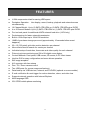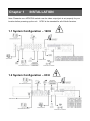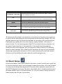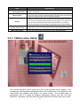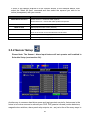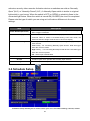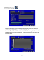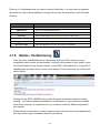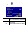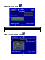
1
H.264 Dual Stream / Pentaplex DVR Series 4/8/16 Channel Owner’s Manual 15540 Herriman Blvd. Noblesville, IN 46060 - www.security-labs.com Customer Support 1-800-774-0284 VER.:1.1, P/N: 264-6 DMS/MBR Copyright – MMX 6 This symbol is intended to alert the user to the presence of unprotected “Dangerous voltage" within the product's enclosure that may be strong enough to cause a risk of electric shock. This symbol is intended to alert the user to the presence of important operating and maintenance (servicing) instructions in the literature accompanying the appliance. WARNING - TO REDUCE THE RISK OF FIRE OR ELECTRIC SHOCK, DO NOT EXPOSE THIS APPLIANCE TO RAIN OR MOISTURE. NOTE: This equipment has been tested and found to comply with the limits for a class digital device, pursuant to part 15 of the FCC Rules. These limits are designed to provide reasonable protection against harmful interference when the equipment is operated in a commercial environment. This equipment generates, uses, and can radiate radio frequency energy and, if not installed and used in accordance with the instruction manual, may cause harmful interference to radio communications. Operation of this equipment in a residential area is likely to cause harmful interference in which case the user will be required to correct the interference at their own expense. Disposal of Old Electrical & Electronic Equipment (Applicable in the European Union and other European countries with separate collection systems) This symbol on the product or on its packaging indicates that this product shall not be treated as household waste. Instead it shall be handed over to the applicable collection point for the recycling of electrical and electronic equipment. By ensuring this product is disposed of correctly, you will help prevent potential negative consequences for the environment and human health, which could otherwise be caused by inappropriate waste handling of this product. The recycling of materials will help to conserve natural resources. For more detailed information about recycling of this product, please contact your local city office, your household waste disposal service or the shop where you purchased the product. • Make sure to disconnect or switch power off before you install the DVR. • There is the danger of an electric shock if the DVR is opened by an unqualified service engineer or installer. • Avoid using the DVR outside of the reference temperature and humidity indicated in the specification. • Avoid exposing the DVR to violent movement or vibration. • Do not use or store the DVR in direct sunlight or near to any source of heat. • Do not place any objects near the vent holes in the case used for air circulation. • Always use the DVR in a well ventilated location to prevent overheating. • There is risk of an explosion if the backup battery is replaced by an incorrect type. 2 TABLE OF CONTENTS Chapter 1 Installation …………………………………………………………… 1.1 System Configuration - 16 Channel ..…………………..………… 1.2 System Configuration - 8 Channel ……………………………..…. 1.3 System Configuration - 4 Channel …………………………..……. 1.4 Hard Disk Installation …………………………………………..…... Chapter 2 QUICK REFERENCE - MENUS and INDICATORS …………….. 2.1 On-Screen Functions and Status Indicators ……………..………. 2.2 Main Menu ………………………………………………..…………. 2.3 Playback Mode …………………………………..…….……………. 2.4 PTZ Mode …………………………………………..……………….. CHAPTER 3 OPERATION AND MENU SETUP …………………………….. 3.1 Log On Screen ………………………………………………..…….. 3.2 Record Setup ………………………………………………..………. 3.3 Event Setup ………………………………………………..………... 3.4 Schedule Setup ……………………………………………..………. 3.5 Camera / Audio Setup ………………………………..…………….. 3.6 Account Setup ………………………………………...……………... 3.7 Network Setup ………………………...……………………………… 3.8 PTZ & RS-485 Setup ………………………………………………… 3.9 System Setup ………………………………………………………… 3.10 Utility Setup …………………………………………………………. 3.11 Diagnostic …………………………………………….……………… Chapter 4 SEARCH & BACKUP…………………….…………….…….………. 4.1 Search Setup ……………………………….………….……………… 4.2 Backup Setup ………………………………………….……………… 4.3 Remote (Network) Backup ……………………………..……………. 4.4 Converting an IRF backup file to an AVI …………….……………... SPECIFICATIONS ………………………………………………..………………. 3 5 5 5 6 6 9 9 12 13 14 15 15 17 19 23 25 27 29 41 42 49 50 51 51 54 56 56 59 FEATURES H.264 compression ideal for saving HDD space Pentaplex Operation: Live display, record, backup, playback and network access simultaneously 16 Channel Model : Up to (3) SATA 1TB HDDs or (2) SATA 1TB HDDs plus DVDR 4 or 8 Channel Models: Up to (2) SATA 1TB HDDs or (1) SATA 1TB HDD plus DVDR Port on back panel for additional eSATA external hard drive (16CH only) Dual streaming for faster network transmission Built-in VGA output up to 1024x768 resolution 16MB of pre-alarm storage per event (approximately 10 seconds before event happens) 22 x 15 (330 point) grid video motion detection per channel Nine criteria items to search for events per channel Individual setup of resolution, frame rate and video quality for each channel Picture-in-picture monitoring and 2X to 8X digital zoom display Control Methods: Front panel, USB mouse, IR remote, & PC client viewer Intuitive GUI for easy configuration and menu driven operation Still image snapshot AVI converter with time stamp Pan / Tilt / Zoom camera control Two USB ports (for mouse usage and backup). Data backup via: USB devices, network, and DVD-RW (optional on some models) E-mail notification & event trigger for motion detection, alarm, and video loss Supports network operation with Internet Explorer Multi-language OSD 3G/ GPRS mobile phone monitoring 4 Chapter 1 INSTALLATION Note: Please be sure NTSC/PAL switch near the video output jack is set properly for your location before powering up the unit. NTSC is the standard for all of North America. 1.1 System Configuration – 16CH 1.2 System Configuration – 8CH 5 1.3 System Configuration – 4CH 1.4 Hard Disk Installation Your unit comes with a hard drive already installed. Four and eight channel models can have a second hard drive or a DVD writer installed. The sixteen channel model may have two additional hard drives, or an additional hard drive plus a DVD writer installed. Up to TWO TERABYTE size hard drives can be used. For best performance, please use the same size and model of hard drive in each location. Always format the hard drive(s) after installing a new one (see section 3.10, Initialization). Please be sure you have saved any data you wish to keep from an existing drive. Formatting will erase all data. 4 / 8 Channel Layout 16 Channel Layout 6 DISCONNECT THE POWER FROM THE DVR BEFORE REMOVING THE COVER. Mount the HDD brackets in a reverse fashion on both sides of the HDD (Figure 1 and 2) similar to the drive already installed in your unit. Figure 1 Figure 2 The red SATA data cables are wired the same at both ends. Please observe the right angle alignment key before inserting the cable into the hard drive or main PC board. The SATA connectors on the main PC board are in order from front to back. Connect your first drive closest to the front panel, then in order towards the back. Connecting the drives out of order will not harm the drives, but makes them easier to locate should they have the same model ID number. ID numbers of the drives are read electronically and displayed in the Utilities Menu. Please refer to figure 3 for more layout and connection information. 7 Figure 3 The eSATA jack on the back panel allows you to connect a fourth drive if desired for a total 4 terabyte capacity (4 x 1TB = 4TB). The eSATA port is on the 16CH model only. Note: Please be sure NTSC/PAL switch near the video output jack is set properly for your location before powering up the unit. NTSC is the standard for all of North America. 8 Chapter 2 QUICK REFERENCE MENUS and INDICATORS 2.1 On Screen Functions Right clicking on the screen with the mouse or using the MENU button on the front panel will activate the NAVIGATION BAR. Graphic Icons Resting the cursor on the SETUP icon will bring up four (Main Menu/ Search/ Backup/ PTZ) menu icons. MAIN MENU. SEARCH SETUP. BACKUP. PTZ CONTROL. Turns the record function ON/OFF (View Normal frame rate must be active see Section 3.2.1). PLAYBACK – Initiates the play function and displays more controls. Resting the cursor on the Display Setup icon will bring up five more display icons (PAUSE/ PIP/ ZOOM/ AUTO SEQ/ LOCK) PAUSE will freeze live video Picture-in-Picture displays two cameras. Right click on the channel number above the smaller view to change the camera shown. ZOOM, 2X to 8X digital zoom AUTO-sequence will rotate through each camera in full screen. Log Off / Activates password access required for next user 9 Full screen display, multiple clicking to switch channels Quad display. 9CH Split-screen display available on 8 and16CH DVRs. 13CH Split-screen display available on16CH DVR. 16CH Split-screen display available on 16CH DVR. 10 On-Screen Status Indicators Recording is ON Number represents the current selected LIVE audio channel (available to 8/ 16CH DVR and option to 4CH DVR). Live Audio is OFF Motion detected Alarm sensor triggered Video loss detected USB device detected DVR is connected to the Internet Auto Sequence is ON Pause mode is ON Front Panel Control LOCK is ON PTZ controls are ON 99% Shows the current hard disk space used (up to 99%). Will remain at 99% during OVERWRITE (continuous recording) mode. Time / Date bar shown on a playback file 11 2.2 MAIN MENU The majority of settings for your DVR are accessed via the MAIN MENU. Adjustment of the settings can be done locally or via the internet. Each sub-menu activated by the icons below are described in greater detail in Chapter 3. When accessing the MAIN MENU via a local network or internet connection, an additional row of icons is displayed in the bottom right corner of the screen. They are described below. Icon / / Description Changes your live PC view from: Low Video Quality (LQ) to High Video Quality (HQ) Note: High may run slower depending on your internet connection. Selects Standard Screen / Maximum Screen. Records live video to your PC. Takes a snapshot and sends it to the Snapshot folder, located inside the DVRemote Folder. Confirm or change your Record and Snapshot storage path folder settings. Open or Close the tool bar 12 2.3 Playback Mode Playback – On Screen Function Icons Press「 」button for Fast Rewind / Speeds : 2x, 4x, 8x, 16x, 32x, 64x Press「 」button for Fast Forward / Speeds : 2x, 4x, 8x, 16x, 32x, 64x / Press「PLAY」/ 「 「 」buttons for Play and to Pause Playback / SLOW」Slow Motion Playback Speeds : 1/2x, 1/4x, 1/8x, 1/16x 「 / 」Stop Playback Playback frame by frame of selected channel Full screen display Quad display 9CH Split-screen display (available only on 8/ 16CH model) 16CH Split-screen display (available only on 16CH model) Digital Zoom into playback video Sends a snapshot image to your USB Flash Drive (if connected). 13 PTZ – On Screen Controls Exit PTZ Mode Preset number (1~64) Go to preset number selected Set current PTZ location at preset number selected. Directional movement arrows Camera ZOOM + (Close Up), ZOOM – (Wide Angle View) Manual focus control for camera Manual iris adjustment for camera (if available) 2.4 PTZ Mode – Commands Using the IR Remote Control PTZ – Control with Hand Held IR Remote Control / SLOW Tilt up. / Tilt down. / Pan to the left. / Pan to the right. ZOOM + Zoom in (close up) ZOOM - Zoom out (wide angle) FOCUS + & FOCUS - Camera focus IRIS + Camera iris-open. IRIS - Camera iris-close. PRESET + NUMBER PLAY + NUMBER To save a preset location Press PRESET and a number key. To go to a preset location Press PLAY and a number key. 14 Chapter 3 OPERATION and MENU SETUP 3.1 Log On Screen If access to your MAIN MENU is protected, using your mouse, left click on the Admin icon to bring up the password entry screen, left click on each numeral or letter of your password, then click on the “Enter” arrow in the bottom right corner. The default password of the administrator is “123456”. Four additional users can be added with up to six levels of access each. Please refer to “3.6 Account Setup” for more information. The navigation arrows and ENTER button on your remote control may be used instead of the mouse. Password Entry Screen Switch between capital and small letters. / Switch between numbers and letters. Press to cancel or choose another login account. Delete the last character. Enter (after login name completed) Space key 15 Right click on the screen to activate the Navigation Bar. Hover your mouse pointer over the Setup icon screen below. to display a second row of icons. Click on Main Menu to display the Use your mouse to click on each menu icon, or use the IR remote control or the front panel controls as described below. Navigating menus with the IR Remote Control or Front Panel Controls (Click MENU button to enter ) MENU Activates the Navigation Bar Scrolls the list of items 16 Change values in selected item ESC Press to cancel or exit setup ENTER Activates the selected menu 3.2 Record Setup Item Description Select STOP to stop recording when the hard drive(s) are full, or OVERWRITE to enable continuous recording. HDD FULL [Stop]:Stop Recording when HDD(s) is full [Overwrite]:Start to overwrite beginning with the oldest data on the HDD, and continue to record. A time/date stamp is added to the video for each channel being recorded. OSD Position Setup The position of the stamp can be adjusted for each channel individually to avoid blocking any important items. Selecting a channel number on this screen, and then OSD Position Setup, allows you to preview where the time/date stamp will be recorded. OSD Position X OSD Position Y Sets the Horizontal placement from 0 to 456, use the arrows on the box or left click on the center of the box to activate a numeric keypad. Sets the Vertical placement from 0 to 456, use the arrows on the box or left click on the center of the box to activate a numeric keypad. 17 Video Preservation Click box to activate. Information stored on the HDD is additionally protected from overwrite for this specified length of time. (Hours) Quality & Frame Rate Allows individual adjustment of both items per channel as described below. Setup 3.2.1 Quality & Frame Rate Setup Increased recording time on a hard drive can be achieved by decreasing the frames per second (FPS) recorded. Continuously recording (Normal) at a slower rate, and event recording at a faster rate is a suggested method of operating your DVR. Recording a static image of an empty office area is a waste of hard drive space. By using video motion detection, or alarm recording triggered by an external device such as a PIR or door switch, a faster frame rate can be then used to record activity as it happens. Reducing the quality or resolution of the images being recorded (smaller file size) is another method of extending the overall record time on a hard drive. Five Quality settings are available on your DVR: Highest, High, Normal, Basic, and Below Basic. Three resolution selections are also available: 720 x 480, 720 x 240, and 360 x 240. Lower quality can be used when larger objects are being recorded, or finer details within an image are not especially important. There is no best setting for all installations. Experiment with the resolution, quality, and FPS settings to see what is best for your situation. The rule of thumb is to use the best possible settings (720 x 480, Highest, and a faster frame rate) that still gives you the total number of days stored on your hard drive that you require. 18 Item View Normal / View Event No. Resolution Quality FPS Description Selects between Normal (continuous) and Event (alarm or motion) record settings per channel Check/ Uncheck the box will enable/ disable record mode of all channels shown on the page, or each channel can be controlled individually. 360 x 240 Basic, 720 x 240 Better, 720 x 480 Best Choose from Below Basic / Basic/ Normal/ High/ Highest. Recording frame rate (1~30). Normal Auto Automatically calculates the maximum FPS for each active channel after you choose a resolution setting in the Normal recording mode. Event Auto Automatically calculates the maximum FPS for each active channel after you choose a resolution setting in the Event recording mode. The Normal and Event frame rate calculators on the left side of the above menu are there to quickly add the total frames per second requested via the resolution settings, FPS, and cameras selected. Up to 240 frames are available for each group of 8 channels that your DVR model may contain (240 for 4 and 8 channel models, and 240 + 240 for the 16 channel model). If a fast recording speed (high FPS) is needed with many cameras, you can select a lower resolution to accomplish this. If the highest resolution setting is needed on most of your cameras, then you may need to select a lower FPS (recording speed) for some cameras. The numbers on the calculators will turn red if your demands are too high. Lowering the resolution or FPS on some cameras will correct this situation. Clicking on the Auto button will quickly adjust the overall settings for you. 3.3 Event Setup As mentioned above, video motion detection and alarm / sensor recording are a great way to conserve hard drive space, limit recordings to meaningful activities, and create a means to quickly find recordings that are pertinent. The video motion detection feature built into this DVR is designed to be one of the best in the industry with 11 sensitivity settings and a selectable detection grid of 330 small squares (22 x 15) per camera. Pinpoint accuracy is made possible with this type of grid system. 19 Item Description Motion Setup Click to go to the Motion Setup Menu Sensor Setup Click to enter the Alarm / Sensor Setup Menu 3.3.1 Motion Setup Please Note: The Motion Detection feature will not operate until enabled in Schedule Setup (next section 3.4). 20 Item Description Motion Alarm Alarm duration time (1~60 seconds). Sets the length of a recording after Duration(Seconds) motion is detected Check the box to Enable/ Disable the popup screen function for ALL channels. When motion is detected during LIVE view mode, the detected channel’s image will then show in full screen display. Select a channel number from the bar list, and check the box to Enable, Motion Popup or uncheck to Disable motion detection for that channel. This gives you a Enable way to choose channels that will use motion detection, and a way to temporarily disable a channel without affecting its other motion settings. Sensitivity Drag the bar, click the arrows◀ ▶, or click on the box to set up a Sensitivity (A lower value = less) value from 0 to 10 for each channel. A lower value equals less sensitivity. Motion Area Setup Click to enter the motion grid selection screen described below 3.3.1.1 Motion Area Setup Right click on the grid screen to activate the sub menu above. The motion detection grid is made up of 330 small squares (22x15 pattern). The concept is to make squares transparent where you want motion to be detected, and mask RED any squares that should not detect motion. The quickest way to accomplish this is to make all squares transparent (active) with the “All Area Detection” command, and then mask the ones that will be inactive with your mouse. 21 If most of the camera channel is to be inactive similar to the example above, then select the “Mask All Area” command and then select the squares you wish to be active (transparent) with your mouse. Item Mask Mouse Selection Description Check the box = mouse will mask squares. Uncheck the box = mouse will make squares transparent. All Area Detection Mask All Area Continue Makes the entire screen active (transparent) Mask (red) the entire screen (inactive) Temporarily turns the selection box OFF while you edit the screen. Right click on the screen to turn the selection box back ON. Exit & Save Exit & Discard Save setup and exit setup page. Cancel setup and exit setup page. 3.3.2 Sensor Setup Please Note: The Sensor / Alarm Input feature will not operate until enabled in Schedule Setup (next section 3.4). Another way to conserve hard drive space and tag important events for fast access in the future is to involve sensors to activate your DVR. PIR (passive infrared) motion detectors, magnetic door switches, alarm panel relay outputs, etc., are just a few of the many ways to 22 activate a security video recorder. Activation devices or switches are sold as “Normally Open” (N.O.) or “Normally Closed” (N.C.). A Normally Open switch is similar to a typical light switch in your house. When the switch is OFF (or OPEN) no electricity flows to the connected light fixture. When the switch is turned ON (CLOSED) the circuit is completed. Please note the type of switch you are using as it will make a difference in the menu settings. Item Alarm Duration(Seconds) Sensor Popup Description Alarm duration time (1~60 seconds). Sets the length of a recording after a trigger is detected. Check the box to Enable/Disable the popup screen function for all channels. When a sensor is activated during LIVE view mode, the detected channel’s image will be shown in full screen display. Sensor Polarity Click or press ▼ to select between Off, Low, and High voltage polarity for each channel Low Polarity:For connecting Normally Open devices. DVR will trigger when the circuit is closed. High Polarity: For connecting Normally Closed devices. DVR will trigger when the circuit is opened. Off:Alarm Input is deactivated. All Off Sets all alarm inputs to OFF. All Low All alarm inputs set to operate with Normally Open devices. All High All alarm inputs set to operate with Normally Closed devices. 3.4 Schedule Setup Schedule Setup allows you to control when your DVR records including: normal, motion 23 detection, and sensor / alarm detection. Busy or high traffic times may be best suited for Normal (continuous) recording, while off peak hours may be better monitored with motion detection or alarm recording. Up to 50 schedules can be set (10 per page / 5 pages) using the left side of the menu above. The right side shows a summary of all schedules by clicking on the Normal, Motion, or Sensor boxes along the top. Holding your mouse pointer over each completed schedule box on the left will also show its settings summarized on the right side of this menu. Clicking on a schedule box on the left side will bring up the Enable menu below. Item Description Click or press▼ Page to select up to 5 pages. Each page provides 10 schedule boxes (50 schedules total). Holiday Setup Up to 50 Holidays can be scheduled. Each Holiday will repeat the settings you enter for “Holiday” below. Normal/Motion/Sensor Shows the summary of settings for each item 3.4.1 Schedule Enable Setup Create up to 50 schedule combinations using the screen above. Virtually all combinations ever needed are possible. Item Description Enable Select one, two, or all three record types Enter the time range you wish to operate the selected record type. Continuous (24/7) is shown above. Select the days of the week you wish to run the selections made above. Holiday will always be checked by itself (no other days checked). Start / End Time Days 24 3.4.2 Holiday Setup Simply click on each day you wish for your DVR to operate on the Holiday schedule. Each selected day will be highlighted in red. The drop list below the months will give you access to the entire year. The counter on the top left will keep track of how many days have been selected out of 50 (Ex: 7/50). Click OK when finished. Please remember to keep your selections for the coming year updated. 3.5 Camera / Audio Setup 25 Each camera channel in your DVR has six video adjustments that can be made. These adjustments can help compensate for the differences among your cameras or their environment. A well balanced matrix view of all cameras at once is possible by fine tuning these items. Item Mask Sharpness Brightness Contrast Description Check the box to Enable/ Disable the live view of the selected camera Drag the bar or press ◀ ▶ to adjust Sharpness of your camera from value 0 to 15. The default value is 1. Drag the bar or press ◀ ▶ to adjust Brightness of your camera from value 0 to 255. The default value is 128. Drag the bar or press ◀ ▶ to adjust Contrast of your camera from value 0 to 255. The default value is 100. Drag the bar or press ◀ ▶ to adjust Chroma (U) of your camera from value Chroma (U) 0 to 255. The default value is 150. Chroma (U) is a further sub component of the more common “Saturation” or “Color” control. Drag the white bar or press ◀ ▶ to adjust Chroma (V) of your camera from Chroma (V) value 0 to 255. The default value is 150. Chroma (V) is also a further sub component of the more common “Saturation” or “Color” control. Drag the white bar or press ◀ ▶ to adjust Hue of your camera from value 0 to Hue 255. The default value is 150. (This function is ineffective in PAL systems. NTSC / North America = OK.) Allows you to title each camera. Left click on the name line to activate Name the alpha / numeric drop list. Up to 14 characters can be entered. Please remember to click the Enter button next to the space bar when finished. Adjusts the audio volume for the available audio channel(s) in LIVE and Recording modes. Volume Only one audio channel can be monitored at a time. While in FULL SCREEN view of a channel with audio connected to its input, click on the speaker icon in the lower left corner of the screen. The speaker icon at the top of the screen will become active, and the active channel number will be shown next to it. 26 3.6 Account Setup The Account Setup menu is used to provide role-based permission independently for each user (maximum of 4 users) to access the DVR. The default admin account is [admin] and the password is “123456”. Item No. Description Check to activate or deactivate the user’s account. User Name Add or edit a user name. Password Use to set up a password for each user. Permissions Change Admin Password Set specific permissions or access areas for each user (see section 3.6.1). Clicking on this box will bring up the entry form described below. Enter to change administrator’s password. 27 3.6.1 Permission Setup Permission Setup is intended to provide individual user (maximum of 4 users) role-based permissions, including access to Setup menus, Network operation, PTZ functions, Playback, Utility, Backup and Masking of specific channels during playback. After you have made your selections, please click the OK button After you have set up the User account(s) you will want the ability to log ON and log OFF when using your DVR on a daily basis. When you are finished with any session and wish to log off, simply click on the Display icon and then the Lock icon on the Navigation Bar. The next user will be prompted to enter his password when attempting to make changes to the DVR’s operation. 28 3.7 Network Setup Please be sure your DVR is connected to your router or modem with the supplied RJ45 type patch cable before proceeding. Before using your DVR on a network, there are three things that you should know about the type of connection you are using. Item 1 – Do you have a Static or Dynamic IP address from your ISP (Internet Service Provider)? A Static IP address does not change, it is provided by your ISP for a minimal extra charge. Item 2 – Are you installing the DVR on a LAN connection (behind a router) or on a WAN (Internet) connection (direct to modem)? Item 3 – Is your internet service Cable or DSL? Glossary of terms: LAN – Local Area Network WAN – Wide Area Network (Internet) ISP – Internet Service Provider ADSL (or DSL) – Asymmetric Digital Subscriber Line DHCP – Dynamic Host Configuration Protocol DNS- Domain Name System (supplied by your ISP) DDNS – Dynamic Domain Name System DMZ – An unprotected zone outside of your firewall 29 Item Connection Type Description Setup mode for network connection: ADSL、DHCP、LAN. HTTP Setup Enter to set up HTTP for remote access into DVR - Section 3.7.2 DDNS Setup Enter to Enable/ Disable DDNS function and set up – Section 3.7.3 Mail Setup Enter to Enable/ Disable Email notification and setup – Section 3.7.5 3.7.1 Networking Setup This DVR supports DHCP, LAN and ADSL access for network connections. A broadband modem (such as DSL or Cable) will normally connect to a router. Your router may have both wired and wireless features. Typically, computers and your DVR can connect to the ports (RJ45 type jacks) on the back of the router. 3.7.1.1 DHCP The DHCP option is the easiest to use for the DVR’s network connection. An IP address will be assigned by the router or modem automatically after the DVR is connected to the router or modem. The router or modem will act as a DHCP host and assign an open local IP address to the DVR. The home or office computers you have on a local network are assigned an IP address in the same fashion. Similarly, your ISP assigns your modem or router an IP address when they connect to the internet. In the screen above, click on DHCP (turns green) if you wish to let your router select a LAN IP address 30 automatically. After exiting this setup menu, the DVR’s IP address will be shown in the lower left portion of the screen. Write this number down. 3.7.1.2 LAN Select LAN for network connection, the following information is required. Item Description IP Address Unique address used to communicate with your DVR. Subnet Mask Can be used to divide or combine networks if needed. Gateway LAN address that directs devices to the wide area network (WAN). DNS System that matches a number (IP address) to a text entered name. Setting your own LAN IP address If you prefer not to use the DHCP function of your router, you may select “LAN” as shown in the above figure. You will need to follow the same IP addressing process that your router uses and set the final “octet” (group of numbers before or after dots) yourself. You will need the following information from your router: 1) The first three octets of the IP address. In the example above they are “192.168.12” The last octet “38” will be a unique number for each computer or device on your LAN. The number you select MUST not be used by any other computer or device on your LAN. If you use DHCP, this unique number is selected automatically. 2) Subnet mask used by your router. In the example above, it is “255.255.0.0” 3) Gateway used by your router. In the example above, it is “192.168.1.254” To obtain the above information, log on to your router using your web browser or the 31 software program that came with your router. All of this information will be contained in your router’s setup page(s). You can also obtain the information from any computer that is connected to the same LAN as your router. Look under “network settings” on your computer. The IP address of the computer, the subnet mask, the DNS address (from your ISP), and the gateway that your router assigned to your computer will be listed. The last item in the setup is the DNS. If you have a router in your system, you may skip this item. Fill in the DNS information if you are connecting your DVR directly to a modem. Typical home or small office LAN setup: Checking your setup You should now be able to view video from your DVR on your PC screen. Open Internet Explorer and enter the IP address of the DVR in the address bar. A window will pop up prompting you to please enter your user name and password. Default user name is admin and the password is 123456. 32 The login page above is generated by the web server in your DVR. If you are not able to view it, please double check your LAN settings, particularly the IP Address and Gateway. After a successful login, you will see a list of hot links. The first link will allow you to view video without downloading the Active-X based viewer program. You may need to temporarily turn off your web shield software to make the initial connection to your PC. Once connected, you can turn your web shield back on. A onetime adjustment of the Active-X settings in Windows Explorer under Tools/Internet Options/Security/Custom Level may also be needed. 33 Security -> Custom Level 34 The second link seen on the opening page will download the DVRemote viewer program to your PC. This is the recommended procedure since it will make future connections to your DVR go faster. The third link connects to a simple JPEG viewer. This sends rapid images to a larger variety of computers, browsers, and 3G mobile phones, but without access menus and multiple view screens. The fourth link is for H264 RTSP. This can be used with QuickTime and non-Windows based computers and mobile devices. This method adds the ability to switch between HQ and LQ video quality streams (not available with the JPEG viewer). The fifth link will download a file player for backups and archived video. 3.7.1.2.1 Internet Access via a Router and Modem Once the local (LAN) connection is established, the next step is gain access through the firewall of the router. The Port Forwarding or DMZ feature of your router will need to be used. In some cases, a second router may be contained within your modem. This will require port forwarding or DMZ settings be done to both the router and the modem. 35 1) Write down the IP Address and HTTP port number that has been assigned to the DVR. 2) Refer to user’s manual of the router or go to http://portforward.com to get assistance with the port forwarding of the router. Entering the LAN IP address of your DVR into the DMZ (Demilitarized Zone) of your router will also place the DVR on the outside of the router’s firewall. 3) From your computer, connect to your router’s settings summary page by entering the local IP address of your router into the address bar of Internet Explorer. Read the Internet port or WAN IP Address being used by the router. If the Internet Port or WAN IP Address is the same as the address that is assigned to your modem (this can be checked at http://security-labs.com/ip.shtml), then you are finished. If the WAN addresses are different, there is another firewall inside the modem to get through. Port forwarding will have to be performed on the router within the modem. Continue with your investigation and adjustments until the Internet IP (WAN) Addresses are the same. Note: There are (2) IP addresses to remember; the local area network (LAN) IP address (the one for the DVR) and the wide area network (WAN) or Internet Address the one to your Modem. The LAN address is used to operate your DVR from computers inside your network (at home or business). The WAN address is used to operate your DVR from the internet (remote locations). 3.7.1.3 ADSL To use a DSL service, a User Name and Password may be required by your DSL provider. Contact your DSL’s customer service. If you are using a modem connected to a router, refer to the previous sections to set up your DVR’s LAN (Manual or DHCP) connection first. 36 3.7.2 HTTP Setup A wide variance exists among internet connection speeds and broadband network capabilities. The network transmission portion of your DVR is highly scalable. Quality and frames-per-second adjustments are available for each channel. The total transmission rate of the DVR is based on 60 FPS global. You can assign a higher frame rate and /or quality setting to more important camera views, and a lower setting to others. This will allow you fine tune your broadband transmission for peak performance. Item Description Enable HTTP Server Gives you a quick way to activate or deactivate your network transmissions. Enter a valid port value from 1 up to 65535. The default value is 80. Port Avoid duplicating a port number already in use on your system. Quality and Frame Rate Setup for Network Transmission No. Quality Individually select each camera you wish to add to a network transmission. Choose from Below Basic / Basic/ Normal/ High/ Highest. FPS Choose a network transmission frame rate (1~30FPS). Auto Adjusts the maximum frame rate based on the average distribution of each channel (total = 60FPS). 37 3.7.3 DDNS Setup Getting a Static IP address from your ISP is the preferred way to go. If you are only able to get a Dynamic IP address (one that changes periodically), you may consider using a DDNS provider. DDNS (Dynamic Domain Name Service) is an internet service which allows you to associate the IP address of your DVR with a name like www.myDVR.com. Some companies such as www.dyndns.org provide this service free of charge. To use the service you must create an account with a DNS service. You may register at DDNS Server: http://www.dyndns.org. Item Description Enable DDNS Check/ Uncheck to Enable/ Disable the DDNS function. DDNS Server Select your preferred DDNS Server Host Name Enter the registered hostname. User Name Enter the user name you created Password Enter the password you created 38 3.7.5 Mail Setup E-mail can be used as a form of notification when an event occurs such as; VIDEO LOSS, MOTION DETECTION, and ALARM / SENSOR). Be sure to activate the check box next to “Enable E-mail Notification” and click “OK” after entering the information that is appropriate for your type of mail service. Click on the “Receiver E-mail” box to get the screen below. 39 Enter up to 10 addresses that you wish to receive notification. You may select or deselect the check box next to each address to change the receiver list as needed. Click OK when finished. Item Enable E-mail Notification SMTP Server Description Check the box to enable/disable E-mail the notification function. Enter your Outgoing Mail Server User Name Enter the user name listed for your e-mail account Password Enter the password you use to access your e-mail account Sender E-mail Enter your e-mail address Trigger Event Select the checkboxes you wish to serve as triggers for e-mail Receiver E-mail Enter the addresses for up to 10 receivers individually. 3.7.6 Mobile / 3G Monitoring Once you have established internet connectivity with your DVR, viewing via your compatible mobile device will be possible. Using the web browser in your device, enter the WAN IP address from remote location, or the DVR’s LAN address if you have Wi-Fi capability and are within reach of your local network. Once connected, you will see the screen below. Clicking on the JPEG VIEWER link provides the most convenient method of mobile viewing. No further software downloads or modifications to your device are needed. Look for the drop box or camera list on your screen to select the different cameras in your system. Please check our web site or contact customer service for the most current options that will require some type of software added to your device. 40 3.8 PTZ & RS-485 Setup Pan/Tilt/Zoom (PTZ) or Speed Dome cameras can be operated from this DVR. Please connect your control data cable (typically one twisted pair in a CAT5 cable) to the RS485(Pin #1) and the RS485+(Pin #14) on the back panel (illustrations shown in Chapter 1). Please make sure polarity (+ and -) is observed. The video cable can be connected to any input on the DVR. Protocol is a type of language or combination of hex data used for communication between devices. Standard protocols are used to allow interoperability between manufacturers. Baud rate is the speed at which the protocol data is sent to a device. The most important step in setting up a PTZ camera is to make sure the Protocol type, PTZ I.D., and Baud Rate selected on the screen above MATCH the settings of your PTZ camera. Protocol = Pelco D or Pelco P, Baud rate = 9600, and PTZ I.D. = 1 are the most common settings used. Please check the owner’s manual of your PTZ camera to confirm or adjust its settings. Item Description Enable PTZ Click the box to Enable/Disable the PTZ function for the channel selected Protocol Pelco P, Pelco D, KND, LiLin, LG, and Samsung are available PTZ ID Click or press ◀ ▶ to change the PTZ ID from 1 to 64. Baud Rate Select a Baud Rate from 2400, 480, 9600, or 19200 RS-485 ID RS-485 Baud Rate *Functions are available for matching with existing wired remote systems. Keyboard 41 *Control of this DVR from a remote location via a wired RS-485 system is possible. Settings are available at the bottom of the above screen. Remote location control via I.P. (Internet or Local Network) is also available and is the currently preferred method of operation. 3.9 System Setup Item Description DVR Name and Location The name and location will show up in the Subject Line of the e-mails sent to you. Language Auto Lock (3 MODES) Display Setup Click or press ▼ to select OSD language. 22 selections are available. After one minute without any menu or function changing activity, the DVR will switch to LIVE mode automatically. The three modes are described below. Re-entering a password is needed to access the DVR once again Function Auto Logout Key Lock Setting Key Lock YES YES Key unlock YES NO Disable NO NO 1) Click or press ◀ ▶ to set up the duration time in seconds for the display of each channel under Auto-Seq mode. Cameras will show full screen in a sequential order. 2)On-Screen Display items; DVR Status, Date/Time, Channel Name can be selected to show or hide. 3) CRT border colors can also be fine tuned on this menu page. 42 3.9.1 Display Setup Item Description Click or press ◀ ▶ to set up the duration time in seconds for the display of Auto-Seq Interval ( Seconds) each channel. Cameras will show full screen in a sequential order. (1~999 seconds). Show OSD On-Screen Display items; DVR Status, Date/Time, Channel Name can be selected to show or hide. CRT Border Color Check the box to set video output for a CRT (Tube versus LCD screen). Color of borders between channels on the screen can be adjusted . 43 3.9.2 Date/ Time Setup Item Description Hour Format Select 12HOUR or 24HOUR format. Date Format Adjustable to MM-DD-YY, DD-MM-YY, or YY-MM-DD. Date/Time Position Places the Date / Time on the top or bottom of the screen. 3.9.2.1 Change Date & Time 44 Manually enter the current date and time with the screen above then click <OK>, or use the automatic internet mode described below in section 3.9.2.3. 3.9.2.2 Time Zone Setup Change the time zone and activate Daylight Saving Time function according to your location. Item Select Time Zone Description Enter to modify GMT from GMT- 13 to GMT+ 13. GMT zones for the United Sates: Eastern -5, Central -6, Mountain -7, and Pacific -8. Daylight Saving Time Activates Daylight Saving Time if applicable in your area. 45 3.9.2.3 Internet Time Setup Synchronize your DVR’s time with an internet time server. Item Description Check to enable the DVR’s automatic synchronization function. Automatic Synchronization Unit will automatically synchronize the time upon rebooting, plus every 24 hours thereafter. Update Now Instantly updates time/date. Be sure the GMT zone is set correctly first and that your internet connection is functional. 46 3.9.3 Device Setup Use the above screen to control the ratio of the speed of the mouse pointer when moving the mouse. Move the slider to the right to increase the velocity of the cursor. Click <OK> when finished. Click on <Buzzer & Relay Setup> on the Device Setup screen to display the options for the key tone, internal buzzer, and relay outputs. 47 Item Mouse Speed Description Adjust the slider bar to your preference. Buzzer & Relay Setup Key Tone Alarm Buzzer Alarm Relay Enable/ Disable the beep heard when pressing the front panel buttons. Enable/ Disable the internal buzzer that can be triggered for HDD Error, Sensor / Alarm Trigger, Motion Detection, and Video Loss. Enable/ Disable the RELAY OUTPUTS that can be triggered for HDD Error, Sensor / Alarm Trigger, Motion Detection, and Video Loss. 3.9.4 Spot Setup In addition to the MAIN monitor output, your DVR also has a SPOT monitor output. A spot monitor is used for public display or secondary office monitoring. Only live camera feeds are sent to the spot monitor in a sequential manner. Functions of the DVR such as; video being played back, menu changes, and backups in progress are not seen by people viewing the spot monitor. Item Auto-Seq. Interval (Seconds) Skip Video Loss Channel Channels Description Sets the duration of each channel shown (1~999 seconds). The spot monitor output will automatically ignore channels without a video signal if selected. Select which channels are to be displayed in the sequence. 48 3.10 Utility Item HDD Initialization (Format). THIS STEP WILL ERASE ALL VIDEO DATA FROM YOUR HARD DRIVE. USB Initialization System Recovery Reset System Events Description Select to enter the hard disk initialization menu. This step should be performed whenever installing a new hard drive, or if you change the time / date settings on your DVR. this menu. Please stop recording before entering System will show all the data (model/ volume) of HDD that is installed in the DVR. Check the HDD you’d like to initialize, and then press “Start”. HDD initialization is successful when the status shows “Succeed”. Clears all data on your USB drive. . Enter USB initialization and press “YES”. The initialization is done when “Succeed” is displayed. Restores all settings to factory default values. Clears the event logs. You can transfer your setup configuration to another (same model) DVR Copy Setup to USB using this command via a USB flash drive. There will be a file named “sdvr.config” on your USB drive when finished. Download Setup from USB Download the configuration file from a USB device into the same model DVR. The operational firmware for your DVR can be upgraded if needed. Please contact Customer Service @ 800-774-0284 for details first. Upgrade improper file installed can also render your unit inoperable! An Please stop recording and backup setup configuration before upgrading. System will reboot automatically when the upgrade is completed. 49 NOTE! DO NOT TURN OFF THE POWER OR UNPLUG THE USB DEVICE DURING THE UPGRADE as it may cause damage to the DVR. 3.11 Diagnostic The diagnostic screen is a great way to see a snapshot of your DVR’s IP and hard drive status. Item Version IP Address Description Shows the current firmware version of DVR Shows the connected IP address of the DVR. If disconnected from network, the screen will display” NETWORK DISCONNECT”. MAC Address MAC Address of DVR. HDD Volume The total capacity of each hard drive in your unit. Used A hardware ID number that never changes. Displays the percentage of space currently used on the hard drive(s) Shows three status indicators; USING (currently in use), GOOD (available HDD Status for use), BAD (not currently compatible for storage, please try the <HDD Initialization> command , Utility Menu, before replacing the drive). Format Time Displays the last date the drive was formatted using the <HDD Initialization> command. 50 Chapter 4 SEARCH & BACKUP 4.1 Search Setup (from Navigation Bar) Item Description Event Search Click to enter the Event Search menu. Time Search Click to enter the Time Search menu. 4.1.1 Event Search (from Navigation Bar) This DVR automatically records events with multiple ways to access them at a later date. If 51 there is recorded video for an event, an arrow icon will be shown to the left side of the time/date information. Rest your cursor on the line and press “enter”, or left click your mouse to playback the recorded event. The arrow icon is necessary since not all event types record video such as; Remote Login, Remote Logout, HDD Full, HDD Error, or if the hard drive has been recently formatted (initialized) and the event logs were not cleared using the Reset System Events command in the Utility Menu. Item Criteria Description Set up conditions for the event search function - Section 4.1.1.1 If more than one page of events is available for review, a drag bar will appear Page at the top of the screen. You may use the drag bar, click on the page arrows, or enter a page number directly in the number box. Date/Time Date/ time when the event occurred. Event types available for searches: Motion : Motion detected Sensor : Alarm sensor trigger Video Loss : Video loss from camera Remote Login : User log-in over a network Remote Logout : User log-out over a network Power On : System power up noted HDD Full : Hard drive is FULL HDD Error : Hard drive error detected Reboot : System Reboot noted Event Type Channel The channel where the event occurred. 52 4.1.1.1 Criteria Setup for Event Search The number of events recorded can be overwhelming. Therefore, you can facilitate event sorting by setting up “criteria”. A “start time” and “end time” for each event search, in addition to all of the items available to check in the screen above can prove to be a great time saver for you. 4.1.2 Time Search (from Navigation Bar) With TIME SEARCH, you can look for a specific period of time to review. Dates with recordings are highlighted with a red square as you move your cursor over them. The year and month can be changed in the boxes at the top of the calendar. 53 Clicking on a date in the calendar activates the above screen. You can enter the specific time you desire in the number boxes, or simply drag the indicator bar over the screen, then click <OK>. 4.2 Backup Setup (from Navigation Bar) You can back-up any segment of recorded data from a specified time frame. Connect a USB flash drive to the port on the front of your DVR (or use an optional DVD recorder). If the DVR does not recognize your USB drive, you may need to format the drive using the USB Initialization step in the Utility Menu. The file extension of the backup file is “.irf”. An IRF file player is also saved in the USB drive. You may convert the .irf file to an AVI format using the AVI converter program located on the included CD as detailed in Section 4.4. 54 To create a backup file: 1) Insert a USB Drive (or use an optional DVDR). Initialize the USB drive in the Utility Menu if it is not recognized by your DVR. 1) Select the duration of the file with From and To 2) Chose the device you wish to send the file to if different from what is shown in the drop box. 3) Click <Refresh> and wait for the Free Space on the selected drive to be displayed 4) Click <Calculate> and wait for the Required Space for the file to be displayed 5) Click <Start> A progress bar will show until “Backup Success” is displayed Item Description Enter the backup file start time From Enter the backup file ending time To Select USB (DVD optional) as the backup device (via the internet the device will be Device PC.) The available space in your backup device Free Space Recalculates or confirms the available space of the backup device Refresh Required Space Calculate Start NOTE: Shows the required size for the backup file after you click <Calculate> Calculates the size of backup file Starts the backup operation. Be sure to confirm the size of backup file will fit on your device BEFORE starting the backup. Do not unplug the USB device or turn off the DVR during the backup process to avoid damage to your unit or loss of data! 55 4.3 Remote (Network) Backup The steps for backing up a file over a network connection are essentially the same. You will be prompted to enter a name for the backup file, and confirm the folder you wish to send it to. 4.4 Converting an IRF Backup file to an AVI format The IRF file format used for backups from your DVR is very efficient. A copy of the IRF file player is included on the USB flash drive each time a backup is done. This will allow greater portability for those who may not have an IRF player on their PC. Another way to increase portability is to convert your backup file to an AVI format. An AVI file is easily read by most media players, and can be e-mailed as an attachment, or copied to a variety of digital storage devices. Open the file IRF to AVI.exe located inside the AVI Converter folder on the included CD to get the screen in Fig.1., click on OPEN IRF (Note: The IRF to AVI.exe file can be copied to your PC for future convenience sake.) 56 Fig. 1 Select an IRF file from the folder they are being stored in. By default, the files are stored in the “Record” folder, which is a sub folder of the DVRemote folder that is generated when “DVR Remote Desktop” is downloaded to your PC from your DVR. The selected file will show in the top box of Fig.2. Fig. 2 57 Click on the CONVERT button. The average frame per second for the converted file will show in the top box of Fig.3. An AVI file for each channel captured will be placed back in the originating IRF file folder. Fig. 3 58 SPECIFICATIONS Model 16 Channel 8 Channel 4 Channel CONNECTOR NTSC / PAL switch Video System Video Input 16CH BNC 8CH BNC Video Output 1CH BNC SPOT Output 1CH BNC VGA Output 1024x768 Audio Input 4CH RCA 1CH RCA Audio Output 1CH RCA Audio Backup YES Sensor 4CH BNC 16 input / 2 output 8 input / 1 output RS-485 Pan / Tilt / Zoom camera USB Port 2 ports Mouse USB mouse IR Remote Controller YES 4 input / 1 output STORAGE HDD Support SATA HDD x 3 (Max. 1TB each) or SATA HDD x2 + DVD writer x1 SATA HDD x2 (Max. 1TB each) or SATA HDD x1 + DVD writer x1 SATA HDD x2 (Max. 1TB each) or SATA HDD x1 + DVD writer x1 DVD Writer optional eSATA External eSATA port on 16CH model OSD Display Division 1,4,9,13,16 1,4,9 14 characters Title RECORDING Video Compression H.264 Audio Compression ADPCM Resolution 720x480, 720x240, 360x240 (NTSC) 720x576, 720x288, 360x288 (PAL) 59 1,4 Frame Rate 120, 240, 480 (NTSC) 60, 120, 240 (NTSC) 100, 200, 400 50, 100, 200 (PAL) (PAL) 60, 120, 120 (NTSC) 50, 100, 100 (PAL) Quality Highest, High, Normal, Basic, Below Basic Record Mode Manual, Schedule, Event(motion detection/sensor) Pre-Alarm Recording Post-Alarm Recording Motion Detection 16MB (around 10 sec) 1-999 sec 22X15 (sensitivity 0~10) PLAYBACK Time, Event Search Mode Playback Speed Backup Mode fast forward/backward 2X/4X/8X/16X/32X/64X slow forward/backward 1/2X,1/4X,1/8X,1/16X play/pause USB flash driver / Network / Optional DVD media NETWORK Network Compression H.264 Network Software Internet Explorer / CMS / 3G Mobile Phone Network Users 5 Remote Notification Text & Email message Service TCP/IP, SMTP, DHCP, DDNS, PPPoE Mobile Device Applications available for remote monitoring OTHER Daylight Saving YES Password 5 users including 1 administrator user authority selectable Event List 10000 Key Lock YES Firmware Update USB device Dimension 430mm (W) x 70mm (H) x 360mm (D) Power Source DC12V Operating Environment 30 ~ 80% RH, 5℃ ~ 40℃ (41℉ ~ 104℉) 60 Limited Product Warranty DVR: ONE YEAR PARTS AND LABOR – HARD DRIVE: MAY VARY WITH MODEL. Should this product proves to be defective in material or workmanship under normal usage, we will provide without charge to the consumer, parts and/or labor necessary to remedy the defect for the period of ONE YEAR from the date of purchase. The warranty period commences on the date that the product is purchased by the consumer. Any implied warranty is also limited to the duration above. THIS WARRANTY DOES NOT COVER THE FOLLOWING: FLUCTUATIONS IN THE POWER SOURCE OR LIGHTNING-RELATED DAMAGE; ATTACHED OR UNATTACHED ACCESSORIES; COSMETIC PARTS SUCH AS KNOBS AND ACCESS DOORS; CABINET DAMAGE, INCLUDING DAMAGE IN TRANSIT; ACCIDENTAL DAMAGE; MISUSE; ABUSE; UNAUTHORIZED PARTS USAGE OR REPAIRS; RECEPTION PROBLEMS DUE TO INADEQUATE SIGNAL; UNAUTHORIZED INTERNAL CONTROL OF ADJUSTMENTS; INSTALLATION; ADJUSTMENT OF CONSUMER CONTROLS; OR ANY OTHER USE OF THE PRODUCT OTHER THAN THAT SPECIFICALLY PRESCRIBED IN THE OWNER'S MANUAL. THIS WARRANTY APPLIES TO PRODUCT SOLD AS NEW AND NOT REMANUFACTURED, RECERTIFIED, OR B STOCK PRODUCTS. THE USER/OWNER OF THIS PRODUCT ASSUMES ALL LIABILITY FOR ANY VIOLATION OF PRIVACY FROM ILLEGAL RECORDINGS MADE ON THIS UNIT. THE USER/OWNER ASSUMES FULL LIABILITY FOR ANY AND ALL RECORDINGS MADE FROM THIS UNIT IN A SECURITY OR SURVEILLANCE OPERATION OR IN ANY OTHER USE. SECURITY LABS IS NOT RESPONSIBLE FOR RECORDINGS THAT VIOLATE LAWS OR THAT MAY PROVE OFFENSIVE OR TEND TO INCRIMINATE ANOTHER INDIVIDUAL. LOCAL, STATE, AND FEDERAL LAWS MUST BE OBSERVED REGARDING ALL RECORDINGS. To obtain warranty service, the consumer must provide the product along with evidence that will positively identify the date that the product was purchased from an authorized product representative, dealer, retailer, or distributor. Prior to shipment, a RETURN AUTHORIZATION must be obtained; this will assist us in more efficient service on your unit, and possibly avoid shipment if the adjustment can be made over the phone. If shipment is made, the cost for postage, insurance and shipping of the product is the responsibility of the owner. THE MANUFACTURER’S OBLIGATION UNDER THIS WARRANTY SHALL BE TO REPLACE SUCH PARTS AND PROVIDE LABOR AS STATED. THE MANUFACTURER WILL NOT BE LIABLE FOR ANY LOSSES OR INCONVENIENCES DIRECT OR INDIRECT, OR CONSEQUENTIAL PROPERTY DAMAGES. To obtain a warranty return authorization number, contact our Customer Service at: Security Labs, Inc. 15540 Herriman Blvd.. Noblesville, IN 46060 CUSTOMER SERVICE -TOLL FREE: 1-800-774-0284 61