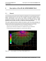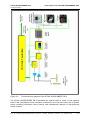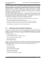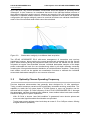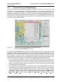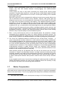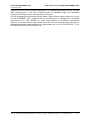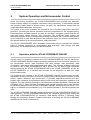
1
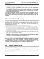
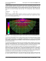
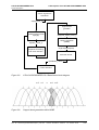
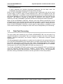
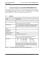
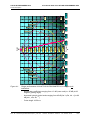
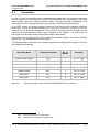
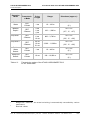
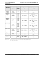
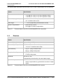
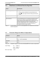
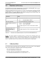
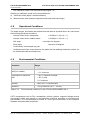
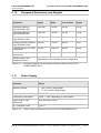
Product Description
ATLAS HYDROSWEEP DS-2
Hydrographic Deep Sea Multibeam Echosounder
Doc.-Id.: HYD-DS2_ProductDescription_16c.doc
Edition: 05.2003/ Version: 1.2 / Status: Final
ATLAS HYDROSWEEP DS-2
Change Log
Product Description
Table of Contents
1
INTRODUCTION .....................................................................................................1-1
2
DESCRIPTION OF THE ATLAS HYDROSWEEP DS-2 ..........................................2-1
2.1
2.2
2.3
2.4
2.5
2.6
2.7
3
GENERAL ................................................................................................................. 2-1
BACKSCATTER DATA FOR SEABED CLASSIFICATION .................................................... 2-3
OPTIMALLY CHOSEN OPERATING FREQUENCY ........................................................... 2-4
“OPEN” FRONT-END TECHNOLOGY ............................................................................ 2-5
MODULAR RECEIVER CONCEPT ................................................................................. 2-5
SOUND VELOCITY AND RAY BENDING ........................................................................ 2-9
MOTION COMPENSATION......................................................................................... 2-10
SYSTEM OPERATION AND ECHOSOUNDER CONTROL ....................................3-1
3.1 OPERATION WITH THE ATLAS HYDROMAP ONLINE................................................ 3-1
3.2 OPERATION VIA ATLAS HYDROMAP CONTROL..................................................... 3-3
3.3 DATA POST-PROCESSING ......................................................................................... 3-7
4
TECHNICAL DATA OF THE ATLAS HYDROSWEEP DS-2 ...................................4-1
4.1 GENERAL ................................................................................................................. 4-1
4.2 TRANSMITTER .......................................................................................................... 4-4
4.3 RECEIVER ................................................................................................................ 4-7
4.4 BEAMFORMER AND BOTTOM DETECTION ALGORITHM ................................................. 4-8
4.5 PARAMETER RANGES FOR MOTION COMPENSATION ................................................... 4-8
4.6 RESOLUTION AND ACCURACY .................................................................................... 4-9
4.7 CALIBRATION MODE.................................................................................................. 4-9
4.8 OPERATIONAL CONDITIONS ..................................................................................... 4-10
4.9 ENVIRONMENTAL CONDITIONS ................................................................................. 4-10
4.10 EQUIPMENT DIMENSIONS AND W EIGHTS............................................................... 4-11
4.11 POWER SUPPLY ................................................................................................. 4-11
5
ABBREVIATIONS ...................................................................................................5-1
6
DELIVERED ATLAS DEEP SEA SYSTEMS ...........................................................6-1
7
REFERENCES ........................................................................................................7-1
Doc. Id.: HYD-DS2_ProductDescription_16c.doc
Edition: 05.2003 / Version: 1.2 / Status: Final
ii
ATLAS HYDROSWEEP DS-2
Change Log
Product Description
CHANGE LOG
Version
CHANGES
Author(s)
Date
1.0
-
Initial version (based upon an existing
product description from Holger Klindt)
Ch. Zwanzig
25.04.2002
1.1
-
Change of ATLAS Hydrographic Logo
S. Birnstiel
01.03.2003
1.2
-
Revision and completion of technical data
Ul. Lütticke
23.05.2003
1.2.1 final
-
minor changes
S. Könnecke
07.10.2003
Doc.-Id.: HYD-DS2_ProductDescription_16c.doc
Edition: 05.2003/ Version: 1.2 / Status: Final
ATLAS HYDROSWEEP DS-2
1 Introduction
Product Description
1
Introduction
The worldwide constitution of National Exclusive Economic Zones (EEZ) focuses the nations
attention on the enormous resource potential of oceanic regimes. The utilisation of vast
areas, extending from inshore to the high seas, offers a broad spectrum of technological
challenges. The future management of these marine resources highly depends on the
availability of appropriate technologies for surveying, monitoring and exploitation. The ATLAS
HYDROSWEEP DS-2 has been developed as a unique surveying tool for continuous and
gap-less acquisition of highly demanded seafloor data. International Marine Research
Institutions, National Hydrographic Services, Offshore Surveyors and Engineers as well as
Environmental Agencies utilise the instrument's outstanding accuracy, resolution and the
wide swath width in a demanding environment.
The ATLAS HYDROSWEEP DS-2 multibeam echosounder utilises an enhanced preformed
beam detection technology in order to overcome classical array aperture limitations. A dualprinciple beamforming device combines traditional, stabilised time-delay beamforming with
ATLAS Hydrographics’ advanced high-resolution bearing discriminator, a technology
originally introduced with ATLAS Hydrographics’ shallow water multibeam echosounder
system ATLAS FANSWEEP 20. Swath angles of up to 120 degrees can be achieved and
resolved into up to 240 independent depth information channels.
ATLAS HYDROSWEEP DS-2 has been designed to meet the following performance
characteristics:
-
The range, to include all world oceans independent of their specific boundary conditions,
i.e. depths from shallow shelf regions all the way down into the abyssal plains and deep
oceanic trenches.
-
The coverage, to provide utmost operational efficiency. With its horizontal "T-type"
transducer array, the ATLAS HYDROSWEEP DS-2 provides coverage of up to 120
degrees.
-
The accuracy, to comply with Hydrographic standards as specified by the International
Hydrographic Organisation, Special Publication No. 44 (see reference /5/). The ATLAS
HYDROSWEEP DS-2 achieves full SP44-compliant data accuracy within swath widths of
typically 2 to 3 times the water depth.
-
The angular resolution, to provide a maximum of operational and scientific value for a
wide variety of applications from object search and detection to route surveys. The
ATLAS HYDROSWEEP DS-2 achieves up to 240 depth data per swath. Acoustic
footprints can be arranged in either an "equal-footprint" or an "equal-angle" pattern in
order to adapt to specific survey conditions.
-
The efficiency, to support the operator from the initial investment phase through to the full
instruments life cycle with innovative solutions to minimise its procurement and
installation costs while simultaneously offering superior operational capabilities in a highly
demanding commercial and technical environment.
With its symmetrical mills-cross transducer configuration, the ATLAS HYDROSWEEP DS-2
allows to acquire simultaneous and independent data sets for:
-
Precise bottom bathymetry with a maximum of 240 depth channels
-
High-resolution 2-D seafloor imaging
Doc.-Id.: HYD-DS2_ProductDescription_16c.doc
Edition: 05.2003/ Version: 1.2 / Status: Final
ATLAS HYDROSWEEP DS-2
1 Introduction
Product Description
-
Full 3-D sonar imaging of the ensonified water column
-
Acoustic measurement of sound velocity distribution for real-time ray correction
-
Calibrated bottom backscatter analysis, providing seafloor sediment classification
-
Look-ahead acoustic navigation for scientific station planning
With the actual topographic bottom profile available in each sounding, all additional data sets
can be viewed online in their correct geographical context. This enables the operator to
correlate on-the-fly all of the above information for an efficient real-time interpretation of the
acquired marine environment.
Doc. Id.: HYD-DS2_ProductDescription_16c.doc
Edition: 05.2003 / Version: 1.2 / Status: Final
1-2
ATLAS HYDROSWEEP DS-2
2 Description of the ATLAS HYDROSWEEP DS-2
Product Description
2
Description of the ATLAS HYDROSWEEP DS-2
2.1
General
The revolutionary new hydro-acoustic transducer configuration, the so-called symmetrical Tshaped transmitter-receiver array has been developed with special emphasis given to
flexible, high-resolution ocean volume and seafloor topography detection. Precisely
synchronised amplitude and phase sampling followed by advanced real-time signal
plausibility filters provide the basis to reach the projected performance and quality
requirements and increase the ability of unambiguous bottom target detection.
This unique, patented technique enables the system to train the normal multibeam fan
around its vertical axis from the normal across track orientation into the for-aft plane. This realignment offers a three-fold advantage over conventional multibeam echosounders:
-
Mean-sound velocity calibration for real-time ray bending corrections.
-
Angular bottom backscatter calibration for reliable bottom type classification.
-
Forward-looking acoustic navigation for scientific station planning.
Figure 2-1:
Sonar diagram of an ATLAS HYDROSWEEP DS-2
Doc. Id.: HYD-DS2_ProductDescription_16c.doc
Edition: 05.2003 / Version: 1.2/ Status: Final
2-1
ATLAS HYDROSWEEP DS-2
2 Description of the ATLAS HYDROSWEEP DS-2
Product Description
Figure 2-2:
Functional block diagram of the ATLAS HYDROSWEEP DS-2
The ATLAS HYDROSWEEP DS-2 ensonifies the seafloor within a sector of 120 degrees.
Each of the "illuminated" bottom elements contributes to the total echo trace with a specific
signal containing information about position and characteristic features of that particular
bottom location.
Doc. Id.: HYD-DS2_ProductDescription_16c.doc
Edition: 05.2003 / Version: 1.2 / Status: Final
2-2
ATLAS HYDROSWEEP DS-2
2 Description of the ATLAS HYDROSWEEP DS-2
Product Description
Upon return of the full bottom echo, the backscattered sound signal is received by an array of
hydrophone elements. The output signals are corrected for differences in the individual
receiving characteristics and amplified to a standard calibrated level by means of individually
adjusted preamplifiers. These circuits are closely mounted to the hydrophones. Thus a high
signal-to-noise ratio is maintained throughout the complete electronic system. Digitally
controlled Time Variable Gain (TVG) amplifiers subsequently correct for acoustic
transmission losses. The properly adjusted analogue signals are sampled and then digitised
by analogue-to-digital flash converters.
A preformed beam analysis combined with the new ATLAS high-resolution bearing
discriminator (High Definition Bearing Estimation – HDBE) allows sorting the information into
up to 240 small, pencil-like acoustic detection elements. The corresponding amplitude and
phase data from each of these channels are subsequently converted into:
-
Precise bottom bathymetry with a maximum of 240 depth channels.
-
High-resolution 2-D seafloor imaging with up to 6 kByte samples per sounding cycle.
-
Full 3-D sonar imaging of the ensonified water column.
-
Acoustic measurement of sound velocity distribution for real-time ray correction.
-
Calibrated bottom backscatter analysis providing seafloor sediment classification.
-
Look-ahead acoustic navigation for scientific station planning.
2.2
Backscatter Data for Seabed Classification
For each of the acoustic beams, the ATLAS HYDROSWEEP DS-2 acquires both the
acoustic echo travel times as well as the corresponding signal amplitudes. These raw
amplitudes, however, are the result of a complex convolution of the following characteristics
and transfer functions:
-
Transmit signal time series
-
Acoustic and electric transducer transfer functions
-
Sea water propagation transfer function
-
Seafloor scatter function
-
Receiver transfer function
In order to provide all necessary data for conversion of the measured relative amplitudes into
absolute acoustic signal levels (which is necessary for backscatter calculations), the ATLAS
HYDROSWEEP DS-2 measures all electric and acoustic system parameters as e.g.:
-
Transmit frequency
-
Acoustic source level
-
Transmit pulse length
-
Acoustic transmitter beam pattern
-
Acoustic receiver beam pattern
-
Receiving voltage response
-
Constant and time variable gain settings
Doc. Id.: HYD-DS2_ProductDescription_16c.doc
Edition: 05.2003 / Version: 1.2/ Status: Final
2-3
ATLAS HYDROSWEEP DS-2
2 Description of the ATLAS HYDROSWEEP DS-2
Product Description
Up to this point, any normal multibeam echosounder would be capable of providing similar
information. It must, however, be considered that each of the individual beams because of
their different alignment angles can only measure one sample of the full angular backscatter
distribution of separate bottom locations. It is therefore important to note that in this classical
configuration the angular ambiguity cannot be resolved and hence an unbiased classification
result of the full ensonified swath width cannot be calculated.
Figure 2-3:
Backscatter ambiguity in multibeam data acquisition
The ATLAS HYDRSWEEP DS-2 mills-cross arrangement of transmitter and receiver
transducer, however, allows training the normal across-track orientated fan into the fore-aft
plane. While steaming along the pre-planned track line and the fan trained into the fore-aft
orientation at regular user-selectable intervals, individual backscatter samples of the depth
profile underneath the track line are simultaneously taken by all depth channels eventually
revealing the full angular backscatter distribution of individual bottom locations. These alongtrack scatter curves can be applied as normalisation functions to calibrate the individual
across-track backscatter samples to one common reference.
2.3
Optimally Chosen Operating Frequency
Previous deep-sea echosounders had generally been designed for 12 kHz operations.
Today, modern transducer ceramics offer significantly increased receiving sensitivities. The
capability to reach the full ocean depth of 10,000 metres or more can therefore now be
achieved with the higher 15.5 kHz frequency of the ATLAS HYDROSWEEP DS-2. Amongst
the advantages, narrower focussing beam patterns, lower ambient noise levels and a smaller
transducer design are of prime importance:
-
With 15.5 kHz, a shorter “near field condition” is generated; hence shorter pulses and
more accurate signal threshold discrimination are provided.
-
Typical open-ocean ambient noise levels drop at a rate of -5 to -6 dB per octave, offering
a higher detection probability.
Doc. Id.: HYD-DS2_ProductDescription_16c.doc
Edition: 05.2003 / Version: 1.2 / Status: Final
2-4
ATLAS HYDROSWEEP DS-2
2 Description of the ATLAS HYDROSWEEP DS-2
Product Description
-
Maintaining the geometrical acoustic beam structure and alignment, a 15.5 kHz
transducer can be shortened by approx. 20%.
-
The seafloor backscatter coefficients are typically higher at 15.5 kHz, providing better
results at larger grazing angles.
-
A 12 kHz signal penetrates more easily into the bottom surface layers. The quality of the
return signal is compromised by this effect, resulting in a reduced accuracy of the travel
time and backscatter measurements.
The ATLAS HYDROSWEEP DS-2 has been optimised for the full application range from
water depths as shallow as 10 metres down to more than 10,000 metres. A successful
customer record gives impressive evidence for the correctly chosen system parameters (see
chapter 6).
2.4
“Open” Front-end Technology
The ATLAS HYDROSWEEP DS-2 has been designed with a very flexible transmitter and
receiver front-end in order to support a number of standard system functions and to be open
for additional user applications, now or in the future. The major differences to other
multibeam systems are four-fold:
1. Transmitting and receiving transducers are of identical construction.
2. The connection between the transducers and the transmitting/receiving amplifiers is
performed via processor-controlled switches. These two features are primarily required
for the patented “Cross Fan Calibration Method”, but they are also providing a unique
computer control capability of the direction of sound emission and reception, either along
or across the vessel’s axis.
3. The transmitter is capable to energise the transducers either in the ODT or in the RDT
mode with roll and pitch stabilised directivity.
4. The receiver is (with the exception of the pre-amplifiers and TVG amplifiers) built-up
completely in digital technology. The digital controlled Time Variable Gain (TVG) can be
overridden via the system operator station (workstation or PC).
The latter two features are primarily designed for optimising the hydro-acoustic functions, to
cope with the conditions differing between shallow and deep water and smooth or rough
bottom and the like, but they also provide a unique flexibility for future application variations,
e.g. backscattering analysis, where the changes of operation parameters could then be
performed by external commands which would override the standard parameters, e.g. TVG
start depth, TVG gain factor or longitudinal fan transmission (calibration mode).
2.5
Modular Receiver Concept
The ATLAS HYDROSWEEP DS-2 transducer array includes separate transmitter and
receiver arrays, each one consisting of 3 modules of 8*12 individual acoustic elements.
The original ATLAS HYDROSWEEP DS Beamformer had been designed as a straightforward time-delay Beamformer with orthogonal 90° envelope sampling and an effective 62
kHz sampling rate per beam.
Doc. Id.: HYD-DS2_ProductDescription_16c.doc
Edition: 05.2003 / Version: 1.2/ Status: Final
2-5
ATLAS HYDROSWEEP DS-2
2 Description of the ATLAS HYDROSWEEP DS-2
Product Description
A bottom-tracking controlled echo processor was fed by the digitised envelope data. An
iterative weighting estimator calculated the echo's centre-of-energy straight from the online
raw data and converted these into the acoustic travel times for each individual acoustic
beam. Due to limited capabilities of real-time data acquisition systems in 1985, except for the
travel times no acoustic envelope data were kept. The resulting beam pattern parameters
were:
Transmitter:
90° • 2,3°
Receiver:
2,3° • 20°
Today, modern inexpensive data acquisition systems do provide the necessary means to
keep and handle the full envelope signal for all acoustic beams (see example below, taken
by an ATLAS HYDROSWEEP DS-2).
Figure 2-4:
Full coverage memory image of sonar buffer of ATLAS HYDROSWEEP DS-2
The ATLAS HYDROSWEEP DS-2 provides advanced signal processing techniques, offering
superior system performance: The algorithms implemented in the ATLAS HYDROSWEEP
DS-2 include a combination of a classical time-delay Beamformer technique and a so-called
“High Definition Bearing Estimation (HDBE)” in order to achieve very high depth resolution in
the across-ship direction.
The acoustic raw signals are picked up by the pre-amplifier signal conditioner and fed into a
coarse time-delay Beamformer. This, however, only serves as an initial preformed beam
conditioner. The raw beam time series comprises unbiased, unmasked full-length envelope
data, each one representing the beam-oriented signal trace for the full sounding cycle.
HDBE is based on the information provided by the classical time-delay Beamformer, i.e. the
amplitude time-series from each beam. The per beam amplitude information is analysed to
arrive at an angular information of the incoming sound wave that is of a much higher
resolution than the angular information derived from the beam pattern alone. Using a priori
knowledge of the beam directivity pattern, the amplitude ratio between adjacent beams is
computed and an across fan arrival angle of the incoming wave is deduced.
The ATLAS HYDROSWEEP DS-2 uses the knowledge of the beam pattern together with the
per beam amplitude information to generate an amplitude-angle trajectory in travel time
Doc. Id.: HYD-DS2_ProductDescription_16c.doc
Edition: 05.2003 / Version: 1.2 / Status: Final
2-6
ATLAS HYDROSWEEP DS-2
2 Description of the ATLAS HYDROSWEEP DS-2
Product Description
space. This trajectory is used to generate a number of so called soft-beams that are used in
conjunction with the hard-beams to arrive at an improved angular resolution of the bottom.
The following processing steps are carried out (see also figure 2-5):
-
The per stave data from the transducer is processed in a classical time-delay
Beamformer.
-
The per beam amplitude information is smoothed and noise is reduced with a noise
reduction algorithm.
-
A number of arithmetic support beams are generated.
-
From the amplitude information of the soft-beams the angle and amplitude function is
computed.
-
The individual amplitude-angle information is associated with the corresponding softbeams.
-
The per beam information off the soft-beams is used to detect the bottom using a
weighted soft-beam approach.
-
Where no information on the bottom could be gained through HDBE, the depth is
detected using the hard-beam patterns.
Considering the required accuracy and the actual signal-to-noise ratio, between 120 and 240
beams can be handled by HDBE. For broadband applications, the current configuration is
preset to 140 nominal beams.
Experience with this innovative beam forming concept have been gained with a variety of
different ATLAS HYDROSWEEP MD-2 and ATLAS HYDROSWEEP DS-2 system
installations (see, for example, the list of delivered ATLAS deep sea systems in chapter 6).
Doc. Id.: HYD-DS2_ProductDescription_16c.doc
Edition: 05.2003 / Version: 1.2/ Status: Final
2-7
ATLAS HYDROSWEEP DS-2
2 Description of the ATLAS HYDROSWEEP DS-2
Product Description
electric signal from
transducer
V(angle,time_i)
support beam
generator
traditional beam former
*b(angle)
A(support_beam_n,time_i)
bearing estimation
(HDBE)
A(beam_n,time_i)
angle,amplitude(time)
amplitude smoothing
and noise reduction
soft beam former
A(softbeam_n,time_i)
bottom detection
Figure 2-5:
ATLAS HYDROSWEEP DS-2 Beamformer block diagram
n-2
Figure 2-6:
n-1
n
n+1 n+2
Support beam generation within HDBE
Doc. Id.: HYD-DS2_ProductDescription_16c.doc
Edition: 05.2003 / Version: 1.2 / Status: Final
2-8
ATLAS HYDROSWEEP DS-2
2 Description of the ATLAS HYDROSWEEP DS-2
Product Description
2.6
Sound Velocity and Ray Bending
The acoustic sound propagation in seawater depends on the physical parameters of the
seawater, i.e. temperature, salinity and ambient pressure. Both, signal amplitudes and
directional spreading are affected. As under normal environmental conditions oceans are
stratified media. Both speed and directional variations of sound propagating through such an
environment under oblique angles can be observed. The directional changes are commonly
referred to as ray bending effects.
Figure 2-7:
Typical sound velocity profile as observed during an
ATLAS HYDROSWEEP DS-2 survey
The ATLAS HYDROSWEEP DS-2 offers four different approaches to compensate for this
propagation effect, which, depending on the survey conditions, always provide the user with
optimally compensated bathymetric data sets. All of these methods can be utilised in realtime. However, if during the later offline processing procedure better and more accurate
oceanographic information becomes available, data re-alignment procedures including sound
velocity corrections are provided in state-of-the-art post-processing software module.
1. As a first and basic approach, the ATLAS HYDROSWEEP DS-2 provides access to a
manual adjustment of sound velocity correction factors. These factors can be derived
from a variety of different sources as e.g. external, separate sound velocity sensors (see
below) or prediction models. Quality and accuracy of such corrections are strictly within
the responsibility of the operator.
2. If an external sound velocity profiler is available, the ATLAS HYDROSWEEP DS-3 allows
interfacing such a device through interface types like e.g. RS 232/422. This enables the
user to efficiently transfer measured profile data in near real-time straight into the
multibeam processor. Commonly used sound velocity profilers are CTD’s (conductivity,
temperature, depth probes), XBTs (expandable bathy thermographic probes), XSVs
(expandable sound velocity probes) and USVs (continuous, undulating sound velocity
Doc. Id.: HYD-DS2_ProductDescription_16c.doc
Edition: 05.2003 / Version: 1.2/ Status: Final
2-9
ATLAS HYDROSWEEP DS-2
2 Description of the ATLAS HYDROSWEEP DS-2
Product Description
probes). These oceanographic probes have to be lowered into and through the water
column. The user can choose between memory-logging and cable-connected
configurations.
CTD’s require the ship to stop while conducting the vertical sound velocity profile
acquisition. At typical winch speeds of 1 metre per second, a Mid-Atlantic station at 5,000
metres would take 10,000 seconds or 2 hours 47 minutes plus handling off the valuable
ship’s and survey time.
Both XBTs and XSVs can be dropped while sailing at normal survey speed without any
risk of interference with the acoustic survey activities. However, both probe types are
designed as a one-time, non-recoverable item, which after full wire length has been paid
out, snap off the connection and drop to the seafloor. Thus additional operating costs of,
depending on the chosen model, 60 US $ to 120 US $ per profile must be added to the
overall survey costs – an additional financial burden which under certain oceanographic
conditions, like e.g. in coastal and/or shelf areas might become a quite significant subject.
USVs are tow fish based continuous profilers undulating between preset minimum and
maximum depth values. Technically, these systems offer perfect control over the acoustic
propagation conditions; however, their high procurement costs as well as their limiting
effects on ship’s manoeuvrability must be considered upfront.
3. Both, in many shelf areas as well as in the abyssal planes, the variations in bottom
topography can be described by means of a simple stationary stochastic process. The
ATLAS HYDROSWEEP DS-2 utilises this fact to calculate the mean sound velocity in the
water column by means of a statistical analysis of a subset of subsequent cross profiles.
4. The Cross Fan Calibration Method is based upon the “ATLAS Ziese1 Principle” – a
unique and patented acoustic method for a near real-time sound velocity assessment.
This method is based on the symmetrical transmit and receive beam pattern of the
ATLAS HYDROSWEEP DS-3. With the multibeam fan trained into the fore-and-aft plane,
an in-situ acoustic assessment of the ray-bending effect under the given oceanographic
conditions can be carried out. This method as compared to normal oceanographic profile
measurements becomes a highly efficient survey tool especially under deep-sea
conditions with no separate ship’s time required. This unique, patented method can save
between 3 and 6 hours of ship’s time every day.
While steaming along the pre-planned track line and the fan trained into the fore-aft
orientation at regular, user-selectable intervals, all depth channels simultaneously take
individual samples of the depth profile underneath the track line. Comparing all of these
measurements of the same bottom profile, however taken under different beam angles, in
a robust, least-square estimator does provide a best-fit mean sound velocity correction
factor.
At the negligible small costs of some extra soundings this method provides a stable and
reliable ray bending correction for most survey conditions without the necessity to stop
the vessel for any kind of time-consuming profile acquisition.
2.7
Motion Compensation
Wide swath sonar systems with slant beam geometry are subject to significant propagation
effects in the water column. Thus for any high-precision bathymetric multibeam echosounder
1
Mr. Ziese was a former senior development manager of ATLAS Hydrographic.
Doc. Id.: HYD-DS2_ProductDescription_16c.doc
Edition: 05.2003 / Version: 1.2 / Status: Final
2-10
ATLAS HYDROSWEEP DS-2
2 Description of the ATLAS HYDROSWEEP DS-2
Product Description
systems, an active real time beam stabilisation is an absolute prerequisite for any accurate
depth measurement. A full 3-axis rotational plus an additional single axis translation
correction including roll, pitch, yaw and heave is required.
ATLAS Hydrographic recommends utilising either a high-precision motion sensor, as e.g. the
ATLAS DYNABASE 2-05, combined with an accurate gyro or, alternatively a combined
instrument as the TSS POS/MV for active beam-steering of multibeam echosounder
systems. The motion sensor may simultaneously be used for real-time heave correction of
optionally connected single-beam survey echosounders as e.g. the ATLAS DESO 17, the
ATLAS DESO 25 or the ATLAS DESO 30.
Doc. Id.: HYD-DS2_ProductDescription_16c.doc
Edition: 05.2003 / Version: 1.2/ Status: Final
2-11
ATLAS HYDROSWEEP DS-2
3 System Operation and Echosounder Control
Product Description
3
System Operation and Echosounder Control
Under most survey conditions, the ATLAS HYDROSWEEP DS-2 provides fully automatic
bottom tracking without any operator intervention being necessary. It automatically adjusts
the operating mode (deep or shallow water), the gain, the transmission voltage and the
range-dependent parameters, as required.
The results of the echo evaluation are transferred into a second independent dual-CPUprocessor, controlling all internal operations and being responsible for the complete timing.
External sensors and data sources, as there are the ship’s navigation system and the roll,
pitch and heave sensor platform, are connected. The measured depth profiles are
assembled together with the corresponding external information into a common data record.
Upon completion of each data acquisition and evaluation cycle, this record is transferred to
the operator station via a local area network (LAN) connection.
The ATLAS HYDROSWEEP DS-2 multibeam echosounder can be operated with different
types of software packages for measurement data acquisition, data storage and data
processing. The possible solutions are described below.
3.1
Operation with the ATLAS HYDROMAP ONLINE
On one hand, it is possible to operate the ATLAS HYDROSWEEP DS-2 via the well-proven
ATLAS HYDROMAP ONLINE software package, providing an entire functional spectrum for
full echosounder control, data acquisition and data storage, data processing, data
visualisation, data export, data printout and data replay. This software package cannot only
be used for the ATLAS HYDROSWEEP DS-2, bur also for all other ATLAS multibeam
echosounders like the ATLAS HYDROSWEEP MD-2, the ATLAS FANSWEEP 20 and the
ATLAS FANSWEEP 15. It includes also functions for the acquisition of data from single
beam echosounders.
The graphical user interface of the ATLAS HYDROMAP ONLINE provides easy and selfexplanatory access to all system functions including survey planning, data acquisition, quality
control, system calibration and maintenance. It provides application-oriented and userfriendly menu operation and guarantees widely uniform and self-explanatory operation of all
modules. The user interface is based on the international software standards X-Windows and
OSF/Motif (OSF = Open Software Foundation) and includes extensive online help facilities.
As hardware platforms for the ATLAS HYDROMAP ONLINE, standard PCs with Linux 7.3 (or
higher) or standard Unix workstations (e.g. from Hewlett Packard or Sun Microsystems) are
used.
The ATLAS HYDROMAP ONLINE includes the modules ATLAS HYDROMAP/ACQUIRE for
data acquisition, ATLAS HYDROMAP/NAVIGATE for navigation planning and control and
the ATLAS HYDROMAP/ECDIS for electronic chart display (ECDIS = Electronic Chart
Display and Information System). Detailed information concerning the ATLAS HYDROMAP
ONLINE can be found in reference /2/.
Doc. Id.: HYD-DS2_ProductDescription_16c.doc
Edition: 05.2003 / Version: 1.2/ Status: Final
3-1
ATLAS HYDROSWEEP DS-2
3 System Operation and Echosounder Control
Product Description
Figure 3-1:
Visualisation within the ATLAS HYDROMAP/ACQUIRE software module
Figure 3-2:
Visualisation within the ATLAS HYDROMAP/NAVIGATE software module
Doc. Id.: HYD-DS2_ProductDescription_16c.doc
Edition: 05.2003 / Version: 1.2 / Status: Final
3-2
ATLAS HYDROSWEEP DS-2
3 System Operation and Echosounder Control
Product Description
3.2
Operation via ATLAS HYDROMAP CONTROL
On the other hand, it is possible to use non-ATLAS software products for measurement data
acquisition, data storage and data processing. In this case, the ATLAS HYDROSWEEP DS-2
is controlled by a software application called ATLAS HYDROMAP CONTROL (see reference
/1/).
ATLAS HYDROMAP CONTROL is a state-of-the-art software product for the operational
control of all ATLAS echosounders, running on PC platforms with Windows NT/2000 (or
higher) or Linux 7.3 (or higher). ATLAS HYDROMAP CONTROL does not include
measurement data acquisition. Therefore, ATLAS HYDROMAP CONTROL is usually
installed together with "external" software packages for data acquisition and data processing
(e.g. ATLAS HYDROMAP NT). However, it is of course possible to install ATLAS
HYDROMAP CONTROL alone on a PC platform. This is useful when special PC platforms
shall be dedicated only for echosounder control, but not for measurement data acquisition.
Besides all functions specific for the control of an ATLAS echosounder, ATLAS HYDROMAP
CONTROL provides the following functionality:
-
Graphical presentations
-
Total quality control
-
Logging of all user transactions and system messages
-
Storage, import and export of different types of parameter sets
-
TPE calculations (TPE = Total Propagated Error)
-
Alarm generation
-
User administration.
ATLAS HYDROMAP CONTROL includes an internal object-relational SQL database, in
which the following information is stored:
-
Predefined sensor definition parameter sets for most of the commercially available
sensors belonging to an echosounder system
-
Predefined sensor control parameter sets for different surveying situations
-
Predefined quality control parameter sets, e.g. concerning the different orders of the IHO
Standards for Hydrographic Surveys (SP44) or the different classes of the USACE
Accuracy Performance Standards for Corps of Engineers Hydrographic Surveys
-
User-defined parameter sets
-
The system log
-
User administration information (user names, permissions and passwords).
At time of delivery, the ATLAS HYDROMAP CONTROL database includes already
predefined sensor definition parameter sets and sensor control parameter sets, which have
been created and approved by ATLAS Hydrographic. At time of delivery, the database also
includes predefined quality control parameter sets referring to quality standards like the IHO
Standards for Hydrographic Surveys according to which surveying may be carried out.
Doc. Id.: HYD-DS2_ProductDescription_16c.doc
Edition: 05.2003 / Version: 1.2/ Status: Final
3-3
ATLAS HYDROSWEEP DS-2
3 System Operation and Echosounder Control
Product Description
Figure 3-3:
Main Window of ATLAS HYDROMAP CONTROL
ATLAS HYDROMAP CONTROL is based upon a client/server architecture including a
CORBA link (CORBA = Common Object Request Broker Architecture) for the communication
between the ATLAS HYDROMAP CONTROL clients and the ATLAS HYDROMAP
CONTROL server. The server includes the object-relational database. Because of the
client/server architecture, it is possible to run several instances of ATLAS HYDROMAP
CONTROL on separate PCs with respect to the same echosounder to be controlled. This
feature is helpful for echosounder remote control or when it shall be possible to control an
echosounder from different places on a ship.
Doc. Id.: HYD-DS2_ProductDescription_16c.doc
Edition: 05.2003 / Version: 1.2 / Status: Final
3-4
ATLAS HYDROSWEEP DS-2
3 System Operation and Echosounder Control
Product Description
Figure 3-4:
Tab "Bathymetry" of the "Control ATLAS HYDROSWEEP DS-2 Sensor"
window
When different instances of ATLAS HYDROMAP CONTROL have been installed on different
PC platforms, the ATLAS HYDROMAP CONTROL server including the internal database is
installed only on one PC platform in order to avoid redundancies in data storage.
As a measure for total quality control of an entire surveying system, ATLAS HYDROMAP
CONTROL logs all relevant system events with an exact time stamp in the internal database.
These events include all user operations, which influence the measurement data quality. In
this context, every change in the echosounder parameters is stored including the time of
change, the values of the changed parameters and the user who performed the change. Also
all system messages (alarms, error messages and warnings) which are internally generated
by the system in reaction of alarms or peripheral malfunctions are stored in the system log.
For an inspection of the system log, ATLAS HYDROMAP CONTROL provides a special
"View Log" window. Within this window, it is possible to specify filter parameters including a
time range, the echosounder type and the message types (e.g. alarms, error messages or
warnings) in order to search for specific log entries. Additionally, it is possible to search for
special keywords. If desired, the displayed log entry results can be printed out. For a very
detailed analysis, the system log can also be inspected by the aid of common database
administration tools. The system log stores the system events over a time interval (history)
that can be defined by the user.
ATLAS HYDROMAP CONTROL provides the possibility to calculate the total propagated
error (TPE) of an echosounder system. The TPE calculations are based upon the stored
accuracy values of the different sensors being part of the echosounder system. The
Doc. Id.: HYD-DS2_ProductDescription_16c.doc
Edition: 05.2003 / Version: 1.2/ Status: Final
3-5
ATLAS HYDROSWEEP DS-2
3 System Operation and Echosounder Control
Product Description
calculated TPE values are compared to allowed threshold values defined by the current
quality standard according to which surveying has to be carried out. The quality standard
selected for TPE threshold values can be, for example, the Special Order of IHO SP44, the
Class 1 of the USACE Accuracy Performance Standards for Hydrographic Surveys or a userdefined quality standard.
It is possible to configure ATLAS HYDROMAP CONTROL in such a manner that alarms are
automatically generated when
-
the calculated TPE values are beyond the threshold values defined by the applied quality
standard or
-
when the transmission of the echosounder is disturbed.
For both types of alarms, it can be individually configured how the alarms shall be presented.
Possible options are acoustic alarms, entries in the message list within the Main Window of
ATLAS HYDROMAP CONTROL and/or alarm message boxes popping up on the screen.
ATLAS HYDROMAP CONTROL provides the possibility to handle the following different
types of parameter sets:
-
Sensor control parameter sets:
A sensor control parameter set includes all parameter values, which are necessary for
the operation of a specific echosounder. Sensor control parameters are for example the
sensor operation mode, the frequency of the transmitted acoustical pulses, the
bathymetric coverage, the side scan coverage, the TVG start gain and the TVG stop
gain. Sensor control parameter sets are with respect to the parameter structure and the
parameter values specific for an echosounder type like the ATLAS HYDROSWEEP DS2.
-
Visualisation parameter sets:
Visualisation parameter sets refer to graphical presentations within ATLAS HYDROMAP
CONTROL and include different kinds of colour tables.
-
Quality control parameter sets:
A quality parameter set includes accuracy values for horizontal positions, depth accuracy
values and minimum sizes for feature detection, which are required by a user-defined or
common quality control standard (e.g. IHO SP 44, Special Order) according to which
surveying has to be carried out. A quality control parameter set includes also settings
with respect to the TPE calculation, alarm generation and alarm presentation.
-
Sensor definition parameter sets:
The definition parameters of a sensor include its product-related parameters like the
sensor type (e.g. multibeam echosounder, motion sensor, c-keel sensor or heading
sensor), the manufacturer of the sensor, the sensor name (e.g. ATLAS HYDROSWEEP
DS-2 or ATLAS DYNABASE), the sensor accuracy and the required calibration intervals.
-
Sensor installation parameter sets:
An installation parameter set includes all installation-related parameters of the sensors
being part of a surveying system. In this context, every sensor within a surveying system
is given a logical name by which for example different sensors of the same type and
name (e.g. two GPS sensors) can be distinguished. The installation-related parameters
of a sensor include – among others – the serial number of the sensor, its installation
position within the ship and the last time of calibration.
Doc. Id.: HYD-DS2_ProductDescription_16c.doc
Edition: 05.2003 / Version: 1.2 / Status: Final
3-6
ATLAS HYDROSWEEP DS-2
3 System Operation and Echosounder Control
Product Description
-
Ship's parameter sets:
A ship's parameter set includes ship-related parameters like the ship's name, the
coordinates of the ship's reference point and the ship's draught.
Within ATLAS HYDROMAP CONTROL, the different types of parameter sets can be saved
for later usage. In order to apply a saved parameter set, it has to be loaded into the user
interface. Additionally, it is possible to export individual parameter sets of different types from
the internal database into files and to import individual parameter sets from files into the
database. This feature is relevant for exchange of parameter sets between different
instances of ATLAS HYDROMAP CONTROL and also for backup and restores purposes.
Within ATLAS HYDROMAP CONTROL, different users with different permissions can be
administrated. All users with administration permission are able to create new user accounts,
to delete existing user accounts and to modify the permission rights of existing accounts.
Within ATLAS HYDROMAP CONTROL, access rights for administration, installation, survey
control and monitoring can be assigned to each user account independently and individually.
3.3
Data Post-Processing
The high quality data collected by the ATLAS HYDROSWEEP DS-2 are the basis for a
complete description of the seabed. This is, for example, possible in the form of charts, 3-D
displays, combined bathymetry and acoustic imagery or backscatter analyses (seabed
classification).
ATLAS Hydrographic is able to deliver a complete set of products for the post-processing not
only of ATLAS HYDROSWEEP DS-2 data but also for all data collected with other sensors of
the ATLAS Hydrographic multibeam and single beam echosounder family. One possible
product for the post-processing of data from the ATLAS HYDROSWEEP DS-2 multibeam
echosounder is the ATLAS HYDROMAP OFFLINE (see reference /3/).
The ATLAS HYDROMAP OFFLINE consists of the modules MANAGE, EDIT and CARIS and
covers an extensive functional spectrum, including – among others – functions for data
editing and data cleaning, data conversion, DTM calculations, 2-D and 3-D visualisations,
side scan viewing, backscatter calculations and the generation of final chart products.
Doc. Id.: HYD-DS2_ProductDescription_16c.doc
Edition: 05.2003 / Version: 1.2/ Status: Final
3-7
ATLAS HYDROSWEEP DS-2
4 Technical Data of the ATLAS HYDROSWEEP DS-2
Product Description
4
Technical Data of the ATLAS HYDROSWEEP DS-2
In the following, basic technical data of the ATLAS HYDROSWEEP DS-2 are provided.
ATLAS Hydrographic reserves the right to alter the technical data of the ATLAS
HYDROSWEEP DS-2 to similar or better standards without further notice.
4.1
General
Feature
Specification
Transmission principle
Stabilised, directional full swath transmission fan
Reception principle
Stabilised directional preformed beam reception with highresolution bearing discriminator (HDBE)
Scanning angle
120°, corresponding to a coverage (swath width) of 3.5 times
the vertical water depth; the achievable coverage depends on
the acoustic conditions; please find more details enclosed.
Beam spacing
(across)
“Equal-footprint” or “equal-angle”
Beam spacing
(longitudinal)
2.3°
Operating frequency
15.5 kHz
Minimum depth
10.0 m below the transducers
Maximum vertical depth
> 11,000 m
The maximum detectable depth depends on the acoustic
conditions; please find more details enclosed.
Swath width
-
120°
(~ 3.7 x water depth):
10 to 4,700m
-
90°
(~ 2.0 x water depth):
10 to 8,000 m
-
60°
(~ 1.5 x water depth):
10 to 11,000m
The actual achievable swath width depends on the acoustic
backscatter properties of the seafloor and the water sound
velocity profile, on the roll conditions (survey mode) and the
pitch conditions (calibration mode) of the vessel. For details
see the following figures.
Table 4-1:
General technical data of the ATLAS HYDROSWEEP DS-2
Doc. Id.: HYD-DS2_ProductDescription_16c.doc
Edition: 05.2003 / Version: 1.2/ Status: Final
4-1
ATLAS HYDROSWEEP DS-2
4 Technical Data of the ATLAS HYDROSWEEP DS-2
8000
45°
60°
10000
Product Description
Noise Level 45 dB
Noise Level 50 dB
6000
Noise Level 55 dB
2000
Coverage
[m]
30°
4000
2000
11000
15°
10000
9000
8000
7000
6000
5000
4000
3000
2000
Depth
[m]
1000
15°
4000
30°
Noise Level 60 dB
6000
Noise Level 60 dB
Noise Level 55 dB
45°
Noise Level 45 dB
60°
10000
8000
Noise Level 50 dB
Figure 4-1:
Range performance of the ATLAS HYDROSWEEP DS-2 for typical silt
sediments:
-
-
-
Backscatter coefficients ranging from -12 dB (near nadir) to -25 dB (at 30
degrees grazing angle)
Assumed isotropic noise levels ranging from 45 dB [rel.1 µPa, Hz -1/2] to 60
dB [rel.1 µPa, Hz -1/2]
Pulse length 12/20 ms
Doc. Id.: HYD-DS2_ProductDescription_16c.doc
Edition: 05.2003 / Version: 1.2 / Status: Final
4-2
ATLAS HYDROSWEEP DS-2
4 Technical Data of the ATLAS HYDROSWEEP DS-2
8000
45°
60°
10000
Product Description
Noise Level 45 dB
Noise Level 50 dB
6000
Noise Level 55 dB
2000
Coverage
[m]
30°
4000
2000
11000
15°
10000
9000
8000
7000
6000
5000
4000
3000
2000
Depth
[m]
1000
15°
4000
30°
Noise Level 60 dB
6000
Noise Level 60 dB
Noise Level 55 dB
45°
Noise Level 45 dB
60°
10000
8000
Noise Level 50 dB
Figure 4-2:
Range performance of the ATLAS HYDROSWEEP DS-2 for typical clay
sediments:
-
-
-
Backscatter coefficients ranging from -25 dB (near nadir) to -33 dB (at 30
degrees grazing angle).
Assumed isotropic noise levels ranging from 45 dB [rel.1 µPa, Hz -1/2] to 60
dB [rel.1 µPa, Hz -1/2].
Pulse length 12/20 ms
Doc. Id.: HYD-DS2_ProductDescription_16c.doc
Edition: 05.2003 / Version: 1.2/ Status: Final
4-3
ATLAS HYDROSWEEP DS-2
4 Technical Data of the ATLAS HYDROSWEEP DS-2
Product Description
4.2
Transmitter
In order to reach the desired system capabilities and specifically the continuous operation
from 10 metres to 10,000 metres, the ATLAS HYDROSWEEP DS-2, depending on the actual
working depth, utilises nine different transmit modes. The system software, depending on the
water depth and the coverage selected by the operator, automatically selects these.
In the RDT modes, all transmit pulses are sent out with minimum time spacing relative to
each other, so that the overall sounding rate is kept at the optimum. Common to all RDT
modes is the roll- and pitch stabilisation. This ensures a maximum transmit energy under all
conditions and consequently projects stable footprints at the seafloor – the prerequisite for
high signal-to-noise ratios and corresponding superior data quality.
At reception time, because of the chosen wide receiving beam width in the fore-aft direction
(approx. 20°), a pitch stabilisation is not required.
The following tables summarise the available operation and transmission modes for Survey
and Calibration soundings.
Operation Mode
Transmission Mode
No. of
Beams
Coverage
Shallow Water Search
ODT
1
36° at -3 dB
Deep Sea Search
ODT
1
36° at -3 dB
Shallow Water
ODT1
1
120° at -5 dB
Medium Depth
RDT
3
90° at -3 dB
Medium Depth
RDT2
5
120° at -5 dB
Deep Sea I
RDT
5
120° at -5 dB
Deep Sea II
RDT
3
90° at -3 dB
Table 4-2:
1
2
Operation modes of the ATLAS HYDROSWEEP DS-2 (overview)
ODT – Omni-Directional Transmission
RDT – Rotational Directional Transmission
Doc. Id.: HYD-DS2_ProductDescription_16c.doc
Edition: 05.2003 / Version: 1.2 / Status: Final
4-4
ATLAS HYDROSWEEP DS-2
4 Technical Data of the ATLAS HYDROSWEEP DS-2
Product Description
Operation
Mode
Pulse
Length
Range3
ODT
1 Beam
1 ms
10 – 100 m
RDT
3 Beams
4 ms
2 ms
4 ms
100 – 1,000 m
RDT
3 Beams
12 ms
6 ms
12 ms
800 – 3,700 m
RDT
3 Beams
24 ms
12 ms
21 ms
3,300 – 11,000 m
Shallow
Water
Search
RDT
1 Beam
1 ms
10 – 400 m
Deep Sea
Search
RDT
1 Beam
10 ms
100 – 12,000 m
Shallow
Water
Medium
Depth I
Deep Sea I
Deep Sea II
Table 4-3:
3
4
Transmissio
n Mode
Directions (approx.) 4
90° x 4.6°
(0°)
90° x 2.3°
(-27°; 0°; +27°)
90° x 2.3°
(-30°; 0°; +30°)
90° x 2.3°
(-30°; 0°; +30°)
36° x 4.6°
(0°)
36° x 2.3°
(0°)
Transmission modes of the ATLAS HYDROSWEEP DS-2
for 90° swath width
Ranges are “nominal”; the actual switching is automatically controlled by various
parameters.
Nominal values
Doc. Id.: HYD-DS2_ProductDescription_16c.doc
Edition: 05.2003 / Version: 1.2/ Status: Final
4-5
ATLAS HYDROSWEEP DS-2
4 Technical Data of the ATLAS HYDROSWEEP DS-2
Product Description
Operation
Mode
Pulse
Length
Range3
ODT
1 Beam
1 ms
10 – 100 m
RDT
5 Beams
4 ms
3 ms
2 ms
3 ms
4 ms
100 – 450 m
RDT
5 Beams
6 ms
4 ms
3 ms
4 ms
6 ms
RDT
5 Beams
12 ms
8 ms
4 ms
8 ms
12 ms
RDT
5 Beams
16 ms
10 ms
8 ms
10 ms
16 ms
3,300 – 5,000 m
Shallow
Water Search
RDT
1 Beam
1 ms
10 – 400 m
Deep Sea
Search
RDT
1 Beam
10 ms
100 – 12,000 m
Shallow
Water
Medium
Depth II
Medium
Depth III
Transmissio
n Mode
Deep Sea III
Deep Sea IV
Table 4-4:
Directions (approx.)4
120° x 4.6°
(0°)
120° x 2.3°
(-54°; -27°; 0°; +27°;
+54°)
120° x 2.3°
400 – 1,000 m
(-54°; -27°; 0°; +27°;
+54°)
120° x 2.3°
800 – 3,700 m
(-54°; -30°; 0°; +30°;
+54°)
120° x 2.3°
(-54°; -30°; 0°; +30°;
+54°)
36° x 4.6°
(0°)
36° x 2.3°
(0°)
Transmission modes of the ATLAS HYDROSWEEP DS-2
for 120° swath width
Doc. Id.: HYD-DS2_ProductDescription_16c.doc
Edition: 05.2003 / Version: 1.2 / Status: Final
4-6
ATLAS HYDROSWEEP DS-2
4 Technical Data of the ATLAS HYDROSWEEP DS-2
Product Description
The following table describes technical data of the ATLAS HYDROSWEEP DS-2 transmitter.
Feature
Specification
Transmission source level
-
> 237 dB [rel.1 µPa] 1 m (in RDT operation mode)
-
> 220 dB [rel.1 µPa] 1 m (in ODT operation mode)
-
2.3° in medium and deep-sea mode
-
4.6° in shallow water mode
Pulse length
-
1 – 60 ms (depending on transmission mode)
Dynamic compensation
-
Pitch and roll (in RDT)
-
Pre-trigger for heave compensation
Beam width (longitudinal)
Table 4-5:
4.3
Technical data of the ATLAS HYDROSWEEP DS-2 transmitter
Receiver
Feature
Specification
Beam width (longitudinal)
Approx. 20° (at - 3dB)
Beam width (across)
-
0.5 to 2.3° in medium and deep-sea mode
-
1.0 to 4.6° in shallow-water mode
-
45 [rel.1 µPa] for shallow water
-
50 [rel.1 µPa] for deep water
-
23 dB for shallow water
-
27 dB for deep water
Input Sensitivity
Reception directivity
Bandwidth
100 Hz to 1 kHz
(Automatically determined by the water depth range)
Dynamic compensation
Table 4-6:
-
Roll
-
Heave compensation by geometrical correction of depth
output
Technical data of the ATLAS HYDROSWEEP DS-2 receiver
Doc. Id.: HYD-DS2_ProductDescription_16c.doc
Edition: 05.2003 / Version: 1.2/ Status: Final
4-7
ATLAS HYDROSWEEP DS-2
4 Technical Data of the ATLAS HYDROSWEEP DS-2
Product Description
4.4
Beamformer and Bottom Detection Algorithm
Feature
Specification
Beam forming principle
2-stage Beamformer structure with:
-
Primary (coarse) stabilised time-delay Beamformer
-
Secondary (fine) high-resolution bearing discriminator
(HDBE)
Primary acoustic channels
59 coarse channels
Depth channels
Up to 240
Bottom detection
The HYDROSWEEP DS-2 evaluates individual acoustic
travel times by means of synchronised amplitude and
phase detection with interlaced centre-of-energy and highresolution bearing discrimination computation with
automatic adaptive gate control. A subsequent series of
advanced plausibility filters increases the ability of
unambiguous bottom target detection.
Table 4-7:
4.5
Technical data of the ATLAS HYDROSWEEP DS-2 Beamformer and bottom
detection algorithm
Parameter Ranges for Motion Compensation
Parameter
Range
Roll angle
± 10° for 120° swath width
± 14° for 90° swath width
Pitch angle
± 10 °
Heave
±5m
Table 4-8:
Parameter ranges for the ATLAS HYDROSWEEP DS-2 motion compensation
Input Scaling:
roll
0.4444 V/°
pitch
0.4444 V/°
heave 2.0 V/m
Max: input voltage:
± 10V
Doc. Id.: HYD-DS2_ProductDescription_16c.doc
Edition: 05.2003 / Version: 1.2 / Status: Final
4-8
ATLAS HYDROSWEEP DS-2
4 Technical Data of the ATLAS HYDROSWEEP DS-2
Product Description
4.6
Resolution and Accuracy
The resolution and accuracy characteristics of the ATLAS HYDROSWEEP DS-2 sensor,
operated in the survey mode, are listed in the table below.
It has to be mentioned that the accuracy of an entire surveying system including an ATLAS
HYDROSWEEP DS-2 is not identical to the accuracy of the ATLAS HYDROSWEEP DS-2
sensor, because it includes additional error sources coming from the motion sensor, the
applied sound velocity probe and other sensors.
Parameter
Value
Depth resolution
-
0.1 m
for 10 – 999 m water depths
-
1m
for water depths > 999 m
Side scan resolution
-
Up to 6 kB samples per sounding cycle
Typical standard deviation of
depth
-
< 0.5 %
for 120° swath width
-
< 0.3 %
for 90° swath width
(for the depth range from 100 m to the maximum water
depth)
Standard deviation of the
mean sound velocity,
calculated from cross-fan
calibration
Table 4-9:
0.5 %
(for the depth range from 100 m to the maximum water
depth)
Resolution and standard deviation of an ATLAS HYDROSWEEP DS-2
Remark: The values stated are expected values in normal survey situations and in the
absence of adverse bottom or environmental conditions. Due to the “longitudinal” swath
calibration method, the overall accuracy includes systematic and stochastic errors of the
sensor. A possible bias due to any unknown sound velocity profile is compensated.
4.7
Calibration Mode
The technical data as specified above are applicable in the survey mode. In the calibration
mode, above specification is applicable within the following constraints:
-
The roll compensation is limited to ±10°.
-
The pitch compensation is limited to ±5°.
-
Accuracy values are not specified for the calibration mode.
-
The estimated standard deviation for 90° swath width is < 1 %.
Doc. Id.: HYD-DS2_ProductDescription_16c.doc
Edition: 05.2003 / Version: 1.2/ Status: Final
4-9
ATLAS HYDROSWEEP DS-2
4 Technical Data of the ATLAS HYDROSWEEP DS-2
Product Description
The calibration mode is not executed at yaw angles > 5°.
-
Switching to calibration mode can be accomplished in:
a)
Automatic mode (depth / travelled distance)
b)
Manual mode (ratio between longitudinal and transversal soundings)
4.8
Operational Conditions
The depth ranges, accuracies and related technical data as specified above are valid under
the following operational conditions:
-
Isotropic noise level in deep water:
< 45 dB [rel.1 µPa, Hz -1/2 ]
-
Isotropic noise level in shallow water:
< 60 dB [rel.1 µPa, Hz -1/2 ]
-
Roll angle:
-
Pitch angle:
-
Continuously uninterrupted ray path
-
Undisturbed acoustic contact between the water and the radiating transducer surface (no
air bubbles beneath the transducers).
4.9
Less than ±10 degrees
Less than ±5 degrees
Environmental Conditions
Parameter
Range
Temperature of underwater
parts (incl. cables)
-
+ 35° C maximum
-
- 4° C minimum
Temperature of electronic
units
-
+ 40° C maximum average
-
+ 50° C peak
-
0° C minimum
Humidity
-
Max. 95%, no condensation
Vibrations
-
0.35 g maximum (at 0 ... 100 Hz)
Table 4-10:
Environmental conditions for the ATLAS HYDROSWEEP DS-2
COTS components such as PCs, workstations, printers, plotters, magnetic storage devices
and storage media shall expose to environmental conditions according to manufacturer’s
specifications. It is recommended to provide an “office type environment” for the computer
hardware and associated peripherals.
Doc. Id.: HYD-DS2_ProductDescription_16c.doc
Edition: 05.2003 / Version: 1.2 / Status: Final
4-10
ATLAS HYDROSWEEP DS-2
4 Technical Data of the ATLAS HYDROSWEEP DS-2
Product Description
4.10
Equipment Dimensions and Weights
Equipment
Height
Width
Front-to-back
Weight
Transmitter cabinet 1
Type SH 6020 A 001
2180 mm
750 mm
420 mm
212 kg
Transmitter cabinet 2
Type SH 6020 A003
2180 mm
750 mm
420 mm
212 kg
Signal processing cabinet
Type GE 6012 A 007
1950 mm
600 mm
600 mm
142 kg
Interface Processor cabinet
Type GE 6028 O 300
500 mm
670 mm
500 mm
50 kg
Transducer array incl. cable
(longitudinal)
350 mm
2839 mm
300 mm
393 kg
Transducer array incl. cable
(transversal)
350 mm
2839 mm
300 mm
393 kg
Operator station and
peripheral devices
Table 4-11:
4.11
Depending on the individual system configuration
Equipment dimensions and weights (nominal values) of the ATLAS
HYDROSWEEP DS-2
Power Supply
Parameter
Range
Operating voltage
-
230 V ±10%, single phase
-
or 115 V ±10%, single phase
Frequency
47 – 63 Hz
Total power consumption
5 kVA – 7 kVA, depending on configuration
Type of fuse in main
switchboard
16 A slow blow (230 V)
No. of separate fuses
6 (min.)
Table 4-12:
Power supply requirements for the ATLAS HYDROSWEEP DS-2
Doc. Id.: HYD-DS2_ProductDescription_16c.doc
Edition: 05.2003 / Version: 1.2/ Status: Final
4-11
ATLAS HYDROSWEEP DS-2
5 Abbreviations
Product Description
5
Abbreviations
ATLAS
ATLAS Hydrographic
CORBA
Common Object Request Broker Architecture
COTS
Commercial Off The Shelf
CTD
Conductivity Temperature and Depth Probe
DESO
Depth Sounder
DS
Deep Sea
DTM
Digital Terrain Model
ECDIS
Electronic Chart Display and Information System
EEZ
Exclusive Economic Zone
GPS
Global Positioning System
HDBE
High Definition Bearing Estimation
IHO
International Hydrographic Organisation
kB
Kilobyte
kHz
Kilohertz
LAN
Local Area Network
MB
Megabyte
MD
Medium Depth
NMEA
National Marine Electronics Association
ODT
Omni-Directional Transmission
OSF
Open Software Foundation
PC
Personal Computer
RDT
Rotational Directional Transmission
SP
Special Publication
SQL
Structured Query Language
TPE
Total Propagated Error
TVG
Time Variable Gain
USACE
U. S. Army Corps of Engineers
USV
Continuous Undulating Sound Velocity Probe
XBT
Expandable Bathy Thermographic Probe
XDR
External Data Representation
XSV
Expandable Sound Velocity Probe
Doc. Id.: HYD-DS2_ProductDescription_16c.doc
Edition: 05.2003 / Version: 1.2/ Status: Final
5-1
ATLAS HYDROSWEEP DS-2
6 Delivered ATLAS Deep Sea Systems
Product Description
6
Delivered ATLAS Deep Sea Systems
Vessel
Customer
Country
Delivery
Date(s)
System
Type
RV METEOR
Bundesministerium für
Forschung und Technologie
Germany
1986, 1995
DS-2
RV
POLARSTERN
Alfred Wegener Institut (AWI),
Bremerhaven
Germany
1989, 1997
DS-2
120°
ORV SAGAR
KANYA
National Institute of
Oceanography, Goa
India
1989
DS
RV MAURICE
EWING
Lamont Doherty Earth
Observatory, Palisades
USA
1989, 2001
DS-2
120°
HDBE
RV THOMAS
THOMPSON
US Navy
University of Washington,
Seattle
USA
1990
DS
RV HAKUREI
MARU II
Metal Mining Agency,
Tokyo
Japan
1991, 2000
DS-2
RV SONNE
Reedereigemeinschaft
Forschungsschifffahrt, Bremen
Germany
1991
DS
RV L’ESPOIR
Svitzer Ltd. / Britsurvey,
Great Yarmouth
United
Kingdom
1994, 1998,
2002
DS-2
120°
HDBE
WFS PLANET
TNSW Emden
Germany
2003
DS-2
120°
HDBE
AKADEMIK
BORIS
PETROV
Russian Academy of Sciences
RAS, Moscow
Russia
2003
DS-2
120°
HDBE
Table 6-1:
Delivered ATLAS HYDROSWEEP DS and DS-2 deep-sea systems
Doc. Id.: HYD-DS2_ProductDescription_16c.doc
Edition: 05.2003 / Version: 1.2/ Status: Final
6-1
ATLAS HYDROSWEEP DS-2
7 References
Product Description
7
References
/1/
ATLAS Hydrographic GmbH:
ATLAS HYDROMAP CONTROL
Product Description
Bremen (Germany), March 2002
/2/
ATLAS Hydrographic GmbH:
ATLAS HYDROMAP ONLINE Version 2.2
User Manual, ED 1044 G 012
Bremen (Germany), 06/01-2001
/3/
ATLAS Hydrographic GmbH:
ATLAS HYDROMAP OFFLINE Version 4.2
User Manual, ED 1045 G 012
Bremen (Germany), 02/01-2001
/4/
ATLAS Hydrographic GmbH:
ATLAS HYDROMAP OFFLINE Mini Version 4.2
User Manual, ED 1051 G 012
Bremen (Germany), 03/01-2001
/5/
International Hydrographic Organization:
IHO Standards for Hydrographic Surveys
Special Publication No. 44
Monaco, 4th Edition, April 1998
/6/
U. S. Army Corps of Engineers:
Hydrographic Surveying
EC 1130-2-210
Washington, D.C. (USA), 1 October 1998
Doc. Id.: HYD-DS2_ProductDescription_16c.doc
Edition: 05.2003 / Version: 1.2/ Status: Final
7-1