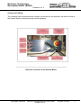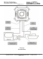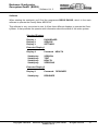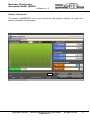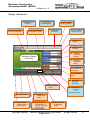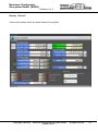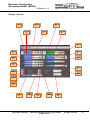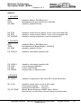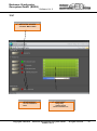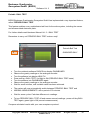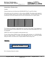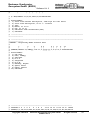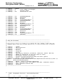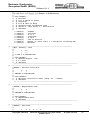
1
Bodensee Gravitymeter Geosystem GmbH (BGGS) Software Vol. 3 Marine Gravity Meter KSS 32- M Instruction Manual Vol. 3 Software Stand 10.06.2012 Vol. 3 of the Manual comprises all details about running the system via a notebook. Author: P. Kewitsch Copyright© 1999-2010 Bodensee Gravitymeter Geosystem GmbH All rights reserved 1 Bodensee Gravitymeter Geosystem GmbH (BGGS) Software Vol. 3 Inhalt Notebook ................................................................................................................................. 3 Set-up and Cabling .................................................................................................................. 4 Cabling Gravity Meter – Notebook ........................................................................................... 6 Navigation Data to the Gravity Meter ................................................................................... 7 NMEA Protocol – General Information ................................................................................. 9 Gravity Data to the Ship ..................................................................................................... 11 Connecting External Systems ............................................................................................ 13 Software ............................................................................................................................. 14 HEALTH ......................................................................................................................... 33 HEALTH ......................................................................................................................... 34 TEST...................................................................................................................................... 38 Periodic BALL TEST ............................................................................................................. 39 DATA DESIGNER ................................................................................................................. 41 License Keys ......................................................................................................................... 45 ZE32 , KE32, PS32, DVFC32 ......................................................................................... 45 License Key........................................................................................................................ 46 If one of the electronic boards has to be replaced a special “Key” has to be generated and installed. Each product of BGGS has its own “Mac Address”. ............................................ 46 In Hyperterminal type ZNL >> read MAC Address immediately. ...................................... 46 In ZNL set marker on Mac Add. ......................................................................................... 46 Type 00-05-C2-DO-02-04 in Flyout “License” .................................................................... 46 ZE32................................................................................................................................... 46 Each board is like a dongle. There is a special license number for each of the boards. .... 46 A special license identification number on each board. It has a format like this: ................ 46 Lic_00-50-C2-D0-02-03...................................................................................................... 46 License key ....................................................................................................................... 46 Installation new Notebook ...................................................................................................... 47 Interpretation of Gravity values .............................................................................................. 48 NMEA Description ................................................................................................................. 51 About us:................................................................................................................................ 59 Copyright© 1999-2010 Bodensee Gravitymeter Geosystem GmbH Software Vol. 3 All rights reserved 2 Bodensee Gravitymeter Geosystem GmbH (BGGS) Software Vol. 3 Notebook The manufacturer Bodensee Gravitymeter Geosystems has provided a notebook together with special software to run the Gravity Meter and handle all necessary information regarding input and output of data. Notebook type: hp® probook 6550 WINDOWS XP WINDOWS 7 until 2011 starts 2012 All customer activities to operate the Gravity Meter can be accomplished via this software. Copyright© 1999-2010 Bodensee Gravitymeter Geosystem GmbH Software Vol. 3 All rights reserved 3 Bodensee Gravitymeter Geosystem GmbH (BGGS) Software Vol. 3 Set-up and Cabling The notebook can be placed at any location convenient for the operator. No direct access to the Gravity Meter is required during normal operation. Ethernet connector at the Gravity Meter Copyright© 1999-2010 Bodensee Gravitymeter Geosystem GmbH Software Vol. 3 All rights reserved 4 Bodensee Gravitymeter Geosystem GmbH (BGGS) Software Vol. 3 Overview All connections Copyright© 1999-2010 Bodensee Gravitymeter Geosystem GmbH Software Vol. 3 All rights reserved 5 Bodensee Gravitymeter Geosystem GmbH (BGGS) Software Vol. 3 Cabling Gravity Meter – Notebook Only one cable is used to connect the Gravity Meter to the notebook. An Ethernet - connector (“Cat. 6”) has been installed at the front panel of the Gravity Meter, matching a patch cable to the notebook. Refer to Hardware Manual, chapter “Front Panel” for details Be aware: Ethernet cables come in two different versions. 1. “Crossed” 2. “Not crossed” The standard connector between Gravity Meter and Notebook needs a “Crossed”-type cable. One cable of about 5 m length is included in the delivery. If a longer cable is needed any extension-cable of the “Not Crossed” type can be used. Do not use a “Crossed”-type cable for extension! It may rersult in a double crossing! On most patch cables, matching industry standards you’ll find a printed mark, indicating if the cable is a cross-type or not. Make sure to use correct cables Copyright© 1999-2010 Bodensee Gravitymeter Geosystem GmbH Software Vol. 3 All rights reserved 6 Bodensee Gravitymeter Geosystem GmbH (BGGS) Software Vol. 3 Navigation Data to the Gravity Meter The KSS32-M Marine Gravity Meter is designed to accept GPS Navigation data. A standard 9 pin serial interface cable will feed navigation data into the Gravity Meter. It has to be plugged into the front plate connector “NAV”. (ref. to page 3) You may use a gender changer, if your connector does not match the 9pin socket on the black front plate. The data protocol conforms to the NMEA-protocol. The NMEA protocol is a fixed data exchange protocol intended for communication between various on-board instruments and marine devices. The NMEA protocol comprises an ASCII data string with a standardised set of characters. The following ASCII settings are a world-wide rule and must be maintained by any device under NMEA protocol. Standard ASCII settings: Abbreviation: 4800 Bd, 8 characters, No Parity, 1 Stop bit 4800, 8,n,1 Any GPS receiver with the capability to send NMEA strings can be connected to the Gravity Meter KSS32 – M. Precautions: No hot swap of devices! Observe precautions when connecting any external GPS device to the “NAV” connector. In some cased the electrical ground of the KSS32-M Gravity Meter and the electrical ground of the GPS device may differ. When attaching the connector, a certain difference in voltage may be present between the “ground pins” of either instruments. The customer is advised to turn OFF the GPS – receiver before connecting the interface cable to the “NAV” connector in the front plate! After this the GPS – receiver may be turned ON again. No hot swap! Copyright© 1999-2010 Bodensee Gravitymeter Geosystem GmbH Software Vol. 3 All rights reserved 7 Bodensee Gravitymeter Geosystem GmbH (BGGS) Software Vol. 3 After sending the first data string to the Gravity Meter the software will accept the protocol. As a result the same data string will be transmitted to the notebook immediately. The menu “DASHBOARD” on the screen of the notebook will display Longitude (LAT) and Latitude (LONG) together with the GPS time “UTC”. In addition a red light will indicate the correct transfer of GPS data. Copyright© 1999-2010 Bodensee Gravitymeter Geosystem GmbH Software Vol. 3 All rights reserved 8 Bodensee Gravitymeter Geosystem GmbH (BGGS) Software Vol. 3 NMEA Protocol – General Information NMEA is a special type of hardware connector together with a software protocol designed for connecting electronic devices to ships. The NMEA protocol is a fixed data exchange protocol intended for communication between various on-board instruments and marine devices. The NMEA protocol comprises an ASCII data string with a standardised set of characters. The following ASCII settings are a world-wide rule and must be maintained by any device under NMEA protocol. Hardware Standard ASCII settings: Abbreviation: 4800 Bd, 8 characters, No Parity, 1 Stop bit 4800, 8,n,1 Software NMEA data strings have the following type of characters: $GPZDA…… $GPRMC…. $GPGGA….. $GPVTG….. §GPGLL…… §PBGGHC…. Time and Date UTC Recommended Minimum Navigation Information Global Positioning System Fix Data Geograhpic Position LAT / LON Harrison Correction Refer to attached list of NMEA examples (end of this document) Copyright© 1999-2010 Bodensee Gravitymeter Geosystem GmbH Software Vol. 3 All rights reserved 9 Bodensee Gravitymeter Geosystem GmbH (BGGS) Software Vol. 3 Copyright© 1999-2010 Bodensee Gravitymeter Geosystem GmbH Software Vol. 3 All rights reserved 10 Bodensee Gravitymeter Geosystem GmbH (BGGS) Software Vol. 3 Gravity Data to the Ship There are two ways to send Gravity data files from the KSS32 M to a dataaquisition system on board the vessel. Standard interface Any serial line interface (COM1….COM 5) connected to the notebook can be used to transmit Gravity Meter files to an external data acquisition system. Ref. to DATA DESIGNER for details Special interface Some customers may wish to use one connector for either NAV INPUT and DATA OUTPUT. The same standard 9 pin serial interface used for the Input of Nav-Data may be used to send Gravity Data to the ship. Before connecting to the interface a special enable switch has to be set. Open top of the Gravity meter case, remove the lower half of the cabinet as well. There is a switch bank on the electronic board, showing KEY0….KEY3 KSS32M in stand-alone configuration Copyright© 1999-2010 Bodensee Gravitymeter Geosystem GmbH Software Vol. 3 All rights reserved 11 Bodensee Gravitymeter Geosystem GmbH (BGGS) Software Vol. 3 KSS32M in the network-attached configuration 1. Special design: (Polarstern) Polarstern wanted to output all measurement data and the input of navigation data via the NAV - RS232 connector on the front board of KSS32M This can be accomplished by turning the ZE Electronics Board ZE32 into bi-directional mode. In this case the NAV input can also serve as an output of data files. Ref. to DATA DESIGNER for details. Board ZE32 has a switchbank with four switches. When turning Key3 to the ON position, The bi-directional mode for RV Polarstern will be set into operation DB9, RS232 „ KSS32M Board ZE32 „NAV“ Server for Data Acquisition on RV Polarstern Switchbank RS232 Key0 Key1 Key2 Key3 ZE32 DB9, RS232 „TEST“ Notebook DACQS Key3 Copyright© 1999-2010 Bodensee Gravitymeter Geosystem GmbH Software Vol. 3 All rights reserved 12 Bodensee Gravitymeter Geosystem GmbH (BGGS) Software Vol. 3 Connecting External Systems External devices, such as Marine Magnetomers, Echosounders can be connected to the KSS32-M Gravity Meter upon request. The customer is advised to contact Bodensee Gravity Meter Geosystems for details. Bodensee Gravity Meter Geosystems will be glad to offer software modules which can be ordered for a variety of customer related instruments. Echosounder: Special software is available to connect echosounders to the KSS32. Make sure they provide a NMEA protocol. You’ll find the software under DATA GRABBER. Copyright© 1999-2010 Bodensee Gravitymeter Geosystem GmbH Software Vol. 3 All rights reserved 13 Bodensee Gravitymeter Geosystem GmbH (BGGS) Software Vol. 3 Software When starting the notebook you’ll find the programme BGGS DACQS, which is the main software to operate the Gravity Meter KSS32-M. This software is very convenient to use. It offers three different displays to operate the Gravity Meter. It also provides the operator with information about the status of the entire system. Standard Displays Display 1: Display 2: Display 3: DASHBOARD SERVICE SETTINGS Extended Display 1 Display 4: Subdisplay: Subdisplay: Subdisplay: Subdisplay: Password HEALTH VERSION TEST HEALTH VERSIONS Extended Display 2 Display 5: Subdisplay: Copyright© 1999-2010 Password: DESIGNER DESIGNER Bodensee Gravitymeter Geosystem GmbH Software Vol. 3 All rights reserved 14 Bodensee Gravitymeter Geosystem GmbH (BGGS) Software Vol. 3 Display “Dashboard” The display “DASHBOARD” is the main information and operation display. All major information is available on this display. Copyright© 1999-2010 Bodensee Gravitymeter Geosystem GmbH Software Vol. 3 All rights reserved 15 Bodensee Gravitymeter Geosystem GmbH (BGGS) Software Vol. 3 Display “Dashboard” 1 Repetition rate of reading 4 Customer selected name of campaign/leg 3 Nav-System transmitting clock 6 Press to select Display „Settings“ 5 „Dashboard“ is selected 2 Time generated by Nav-System of vessel 7 Press to select Display „Device“ 8 Display actual Latitude 9 Display actual Longitude 10 Horizontal accelleration Heading 11 Horizontal accelleration Rolling Analogue Display for Gravity 12 Bessel-Filter Time constant for Raw gravity. 13 Bessel Filter Order. 14 21. start extended display 16 Status indicator KSS 32-M 18 Status indicator KSS32 is running, but OFFLINE Copyright© 1999-2010 Press switch to start Data Recording 15 Gravitymeter ON / OFF or Switch to Stand By 20 Reading of relative gravity (mGal) 19 Status indicator Gravitymeter not sending data. Press switch to start DATA RECORDING 17 Status indicator for Navigation System Bodensee Gravitymeter Geosystem GmbH Software Vol. 3 All rights reserved 16 Bodensee Gravitymeter Geosystem GmbH (BGGS) Software Vol. 3 Display “Dashboard” Description of display and soft keys 1. Repetition rate of reading. Updates new Gravity values every xxx msec. You may change the settings by moving the cursor into field “Update”. Than change number. 2. Navigation system is transmitting the clock signal. The internal clock of the notebook is now controlled by navigation system. This feature guarantees highest precision. 3. Time is generated by navigation system of vessel. 4. Customer selected name of campaign / leg. 5. Soft key press to select another display “SETTINGS”. 6. Display “DASHBOARD” is selected. Indicates which display has been selected. 7. Soft key press to select another display “DEVICE” 8. Display shows actual latitude. 9. Display shows actual longitude. 10. Display shows horizontal acceleration in the direction of heading. 11. Display shows horizontal acceleration in the direction of rolling. 12. Bessel-Filter time constant. Has the same effect as the previous >SEASTATE< Refer to list of SEASTATE on page 51 of Hardware manual. 13. Bessel-Filter order. Has the same effect as the previous >SEASTATE< Refer to list of SEASTATE on page 51 of Hardware manual. 14. Press soft key to start/stop data recording. The text of this soft key will change accordingly 15. Press soft key to turn Gravity Meter ON Press soft key to turn Gravity Meter OFF Press soft key to turn Gravity Meter STAND BY The text of this soft key will change accordingly Copyright© 1999-2010 Bodensee Gravitymeter Geosystem GmbH Software Vol. 3 All rights reserved 17 Bodensee Gravitymeter Geosystem GmbH (BGGS) Software Vol. 3 16. Status indicator for KSS32-M. 17. Status indicator for navigation system. 18. Status indicator: KSS32-M is running but presently OFFLINE. 19. Status indicator: KSS is not sending data. Press switch to start Data Recording 20. Reading of relative gravity (mGal) 21. HEALTH and DATA DESIGNER Start extended display by inserting password HEALTH or DATA DESIGNER. A new word HEALTH will appear in windows 5 to 7 (see above). Click on HEALTH to open displays: Extended Displays for special Operations Maindisplay : HEALTH Subdisplays: VERSIONS HEALTH TEST MAGIC EDIT Use password DATA DESIGNER for modifying data strings. A new word DATA DESIGNER will appear in windows 5 to 7 (see above). Click on DATA DESIGNER to open displays: Copyright© 1999-2010 Bodensee Gravitymeter Geosystem GmbH Software Vol. 3 All rights reserved 18 Bodensee Gravitymeter Geosystem GmbH (BGGS) Software Vol. 3 Copyright© 1999-2010 Bodensee Gravitymeter Geosystem GmbH Software Vol. 3 All rights reserved 19 Bodensee Gravitymeter Geosystem GmbH (BGGS) Software Vol. 3 Display “Settings” A number of important settings can be fed into the system Choose your language Copyright© 1999-2010 Bodensee Gravitymeter Geosystem GmbH Software Vol. 3 All rights reserved 20 Bodensee Gravitymeter Geosystem GmbH (BGGS) Software Vol. 3 Display “Settings” 1 Set COM-port, Baudrate etc 2 Select Data-file to store Gravity 3 Display „Settings“ is selected 4 ID Choose your language 5 Sprache Save Settings 6 Insert absolute harbour gravity value for data processing 7 Insert relative harbour gravity value for data processing 8 Insert estimated seabed rock density for data processing Press SAVE SETTINGS after completion of insertion the new values. Copyright© 1999-2010 Bodensee Gravitymeter Geosystem GmbH Software Vol. 3 All rights reserved 21 Bodensee Gravitymeter Geosystem GmbH (BGGS) Software Vol. 3 Display “Settings” 1 Set Port-Number (COM2 – COM5), set communication parameter, baud rate. 2 Select path for data-files to store CSV-files. 3 Display “SETTINGS” is actually selected. 4 Set ID 5 Select language. You must restart the notebook after changing language 6 Insert absolute gravity value in mGal at the mooring place of vessel. 7 Insert relative harbor gravity value for data processing. 8 Insert estimated seabed rock density for data processing Copyright© 1999-2010 Bodensee Gravitymeter Geosystem GmbH Software Vol. 3 All rights reserved 22 Bodensee Gravitymeter Geosystem GmbH (BGGS) Software Vol. 3 Copyright© 1999-2010 Bodensee Gravitymeter Geosystem GmbH Software Vol. 3 All rights reserved 23 Bodensee Gravitymeter Geosystem GmbH (BGGS) Software Vol. 3 Display “Service” Various information about the actual status of the system. Copyright© 1999-2010 Bodensee Gravitymeter Geosystem GmbH Software Vol. 3 All rights reserved 24 Bodensee Gravitymeter Geosystem GmbH (BGGS) Software Vol. 3 Display “Service” 1 5 3 2 6 4 7 11 8 12 10 13 9 14 22 15 16 17 18 Copyright© 1999-2010 19 20 21 Bodensee Gravitymeter Geosystem GmbH Software Vol. 3 All rights reserved 25 Bodensee Gravitymeter Geosystem GmbH (BGGS) Software Vol. 3 Copyright© 1999-2010 Bodensee Gravitymeter Geosystem GmbH Software Vol. 3 All rights reserved 26 Bodensee Gravitymeter Geosystem GmbH (BGGS) Software Vol. 3 Display “Service” 1 Arresting position for gimbal frames. Indicates actual offset-angel for X-axis. 2 Arresting position for gimbal frames. Indicates actual offset-angel for Y-axis. 3 Arresting position for gimbal frames. Actual angle, value taken from potentiometers. 4 Arresting position for gimbal frames. Actual angle, value taken from potentiometers. If the arresting bolt does not fit into arresting hole beneath the sensor, press the icon IDX. Than press the blue field KE_PXOFFSET. The correct OFFSET angle will be stored. Proceed with KS_PYOFFSET respectively. Than press 21to store data. 5 KE_AX_OFFS, actual displacement of gimbal frame X-axis in m/s². May be used for parabola calibration. 6 KE_AY_OFFS, actual displacement of gimbal frame Y-axis in m/s². May be used for parabola calibration. 7 Scale factor of gravity sensor. 8 Filter characteristics of sensor without external filters 9 Installation of Gravity Meter on board the vessel. Direction of roll axis in reference to the middle axis of platform. Ref. to Manual Part I 10 Indicates actual voltage of caging motor. No customer serviceable feature! 11 Factory setting for motor position “CAGING”. No customer serviceable feature! (Refer to internal service manual.) Factory setting for motor position “MEASUREMENT” No customer serviceable feature! (Refer to internal service manual.) Factory setting for motor pos. “BALL CALIBRATION” No customer serviceable feature! (Refer to internal service manual.) 12 13 14 Earth rate compensation. No customer serviceable feature! 15 Coriolis compensation. No customer serviceable feature! 16 Turn manouvre compensation. Press if required. Press 21 afterwards. Copyright© 1999-2010 Bodensee Gravitymeter Geosystem GmbH Software Vol. 3 All rights reserved 27 Bodensee Gravitymeter Geosystem GmbH (BGGS) Software Vol. 3 17 Turning Compensation Threshold. The value (m/s2) of the threshold can be selected according to requirements. (ref. to curve compensation) During rough sea conditions the ship is likely to move to all directions thus generating false accellerations. These accellerations may be misinterpreted as coming from short turning manouvres. In this case the processor is going to switch OFF the accellerometers in short intervals. To avoid these interruptions, the customer may set the threshold value to a higher value. 18 Eötvös correction 19 Bouguer correction 20 Free Air correction 21 Send values to KSS. Must be engaged after any new settings have been made on this display. 22 Insert gyro parameter. New parameter must be inserted after replacing the gyro. ref. to Hardware Vol. II, gyro Operation procedure: If the customer wants to change any of the customer selectable values, proceed as follows: Change settings: press soft key “>” of the desired line, example: GS_MOTCAGE 1740mV the light will turn green insert new value press RETURN on the keyboard of notebook. new value for GS_MOTCAGE is installed Press field 21 Return to “DASHBOARD” Copyright© 1999-2010 Bodensee Gravitymeter Geosystem GmbH Software Vol. 3 All rights reserved 28 Bodensee Gravitymeter Geosystem GmbH (BGGS) Software Vol. 3 Curve Compensation When turning the vessel into a curve, the horizontal acceleration will have a considerable influence on the stabilized platform. The effect of the additional acceleration (horizontal vector) can tilt the gyro table for a certain amount. As long as precise satellite navigation is available the characteristics of the curve can be calculated (i.e; radius; speed). These data give a possibility to determine the actual value of the acceleration. The software is now prepared to add a proper OFFSET to either axis of the platform in order to restore the real vertical position of the gravity sensor. As soon as the vessel is resuming a straight course, the OFFSET will be reduced to zero again. Remember that you have to maintain the correct installation of the gravity meter with respect to the long axis of the vessel. Read¨ Installation Volume 1, chapter Installation on board You can turn ON / OFF the function CURVE COMPENSATION. Ref. to Menu SERVICE. In order to inhibit CURVE COMPENSATION, you have to set COMPENSATION THRESHOLD to any very high value. For example to 99 ms-2 Normal value must be 0,2 ms-2 Copyright© 1999-2010 Bodensee Gravitymeter Geosystem GmbH Software Vol. 3 All rights reserved 29 Bodensee Gravitymeter Geosystem GmbH (BGGS) Software Vol. 3 Copyright© 1999-2010 Bodensee Gravitymeter Geosystem GmbH Software Vol. 3 All rights reserved 30 Bodensee Gravitymeter Geosystem GmbH (BGGS) Software Vol. 3 Extended Displays for special Operations These displays offer access to more sophisticated tools. It is highly recommended not to use them, unless you are really familiar with the system. You’ll get access to these displays by typing “HEALTH” in DASHBOARD, field 21. (refer to DASHBOARD) Extended display 1 : HEALTH & TESTS Subdisplays: VERSIONS HEALTH TEST MAGIC EDIT In case you want to block access to the HEALTH – functions, type “UNHEALTH” into the same field 21. Extended display 2 : DESIGNER Subdisplay: DATA DESIGNER Copyright© 1999-2010 Bodensee Gravitymeter Geosystem GmbH Software Vol. 3 All rights reserved 31 Bodensee Gravitymeter Geosystem GmbH (BGGS) Software Vol. 3 VERSIONS The display “Versions & Tests” is intended to inform the service – man about the last firmware update. There are no customer related functions. Copyright© 1999-2010 Bodensee Gravitymeter Geosystem GmbH Software Vol. 3 All rights reserved 32 Bodensee Gravitymeter Geosystem GmbH (BGGS) Software Vol. 3 HEALTH Copyright© 1999-2010 Bodensee Gravitymeter Geosystem GmbH Software Vol. 3 All rights reserved 33 Bodensee Gravitymeter Geosystem GmbH (BGGS) Software Vol. 3 HEALTH 1. GyroElectronics 2. 5. Graphic display Power supply 28 V Status Copyright© 1999-2010 Power Supply 3. Centralelectronics 6. Graphic display Gravity sensor temperature 4. VoltageFrequencyConverter 7. Graphic display VF-Converter internal temp. Bodensee Gravitymeter Geosystem GmbH Software Vol. 3 All rights reserved 34 Bodensee Gravitymeter Geosystem GmbH (BGGS) Software Vol. 3 HEALTH 1. KE32.BITE BITE KE32 KE_P28V . . . . KE_ITRX KE_ITRY KE_HSTEMP stands for “Built In Test Electronics” Kreiselelektronik (gyro electronics), KSS32M stands for positive 28 Volts stands for current torquer (Motor) X-axis, must not exceed 0,5A stands for current torquer (Motor) Y-axis, must not exceed 0,5A stands for housing temperature, must not exceed 40°C 2. PS32.BITE BITE PS32 KE_P28V . PS_VCELLO . . . . . . PS_VCELL9 PS_ICAP PS_IOUT PS_HTEMP stands for “Built In Test Electronics” Kreiselelektronik (Power Supply), KSS32 M stands for positive 28 Volts stands for cell-voltage (capacitor) #0 stands for cell-voltage (capacitor) #9 current charging capacitors current output of cap. housing temp. of capacitor-bank 3. ZE32.BITE ZE_VP28V . . ZE_IP18V GS_NTVTEMP stands for voltage positiv 28V inside ZE (Central electronics) stands for sensor input current of 18V supply during sensor heating: max 0,5A during normal operation: max 0,3 A Gravity Sensor temperatur of NTC. Appr.1380mV. Must not vary for more than a few mV during normal operation. Copyright© 1999-2010 Bodensee Gravitymeter Geosystem GmbH Software Vol. 3 All rights reserved 35 Bodensee Gravitymeter Geosystem GmbH (BGGS) Software Vol. 3 4. VFC.BITE VF_VP15V . . . VF_VP3V3 VF_REFTEMP stands for Voltage Frequency Converter, pos. supply voltage 15V stands for Voltage frequency converter, pos. supply voltage 3,3V internal NTC temp. of voltage reference Graphs 5. KE_P28V (V) graph shows status of 28V source 6. GS_NTCTEMP graph shows stability of NTC inside sensor (mV). 7. VF_REFTEMP graph shows stability of NTC inside VFC (mV). The absolute values of both GS_NTCTEMP and VF_REFTEMP are not important for the customer. They have been pre-installed in the factory. But they must be constant values. In case of malfunction of the gravitymeter the customer should check the values. For normal operation the graphs must show a horizontal line, indicating correct temperature inside the devices. Copyright© 1999-2010 Bodensee Gravitymeter Geosystem GmbH Software Vol. 3 All rights reserved 36 Bodensee Gravitymeter Geosystem GmbH (BGGS) Software Vol. 3 Copyright© 1999-2010 Bodensee Gravitymeter Geosystem GmbH Software Vol. 3 All rights reserved 37 Bodensee Gravitymeter Geosystem GmbH (BGGS) Software Vol. 3 TEST 1 Start of test -function “Periodic BALL TEST” All other displays are not customer related Copyright© 1999-2010 2. Graph shows raw gravity voltage output. Not for customer use Bodensee Gravitymeter Geosystem GmbH Software Vol. 3 All rights reserved 38 Bodensee Gravitymeter Geosystem GmbH (BGGS) Software Vol. 3 Periodic BALL TEST BGGS Bodensee Gravitymeter Geosystem GmbH has implemented a very important feature, called PERIODIC BALL TEST. This feature enables a very sophisticated self test for the entire system, including the sensor and all associated electronic parts. For further details read Hardware Manual Vol. 2 – BALL TEST Remember to carry out PERIODIC BALL TEST onshore only! Periodic Ball Test 1 ONSHORE ONLY Turn the notebook software DAQCS into display DASHBOARD Observe the gravity readings or the analogue recorder. Turn the software into display HEALTH Press soft key: BALL TEST, red light is ON (PERIODIC BALL TEST starts) Turn the software into DASHBOARD again Observe the gravity readings or the analogue recorder. Wait for some minutes, until a stabile value has been achieved. The system will now automatically switch between PERIODIC BALL TEST and NORMAL MEASUREMENTS with a period of 30 minutes Wait for some cycles. Calculate difference in readings. To turn PERIODIC BALL TEST off and resume normal readings: press soft key BALL TEST again, green light is ON (normal measurements) Compare calculated results with your own acceptance protocol. Copyright© 1999-2010 Bodensee Gravitymeter Geosystem GmbH Software Vol. 3 All rights reserved 39 Bodensee Gravitymeter Geosystem GmbH (BGGS) Software Vol. 3 Copyright© 1999-2010 Bodensee Gravitymeter Geosystem GmbH Software Vol. 3 All rights reserved 40 Bodensee Gravitymeter Geosystem GmbH (BGGS) Software Vol. 3 DATA DESIGNER Copyright© 1999-2010 Bodensee Gravitymeter Geosystem GmbH Software Vol. 3 All rights reserved 41 Bodensee Gravitymeter Geosystem GmbH (BGGS) Software Vol. 3 1 Select output connector or type of file. 2 3 4 5 store all data 6 Select file and folder for storage 7 8 Browser for various data sources and variables 9 Insert / remove selected file Copyright© 1999-2010 10 This is the data output string Bodensee Gravitymeter Geosystem GmbH Software Vol. 3 11 Details of data output string All rights reserved 42 Bodensee Gravitymeter Geosystem GmbH (BGGS) Software Vol. 3 Detailed description of display DATA DESIGNER 1 Select output connector or type of file. 2 3 4 5 Store all data after completion 6 Select file and folder for storage 7 8 Browser for various data sources and variables 9 Insert or remove selected file 10 Data string customized according to client 11 List and desciption of data string Copyright© 1999-2010 Bodensee Gravitymeter Geosystem GmbH Software Vol. 3 All rights reserved 43 Bodensee Gravitymeter Geosystem GmbH (BGGS) Software Vol. 3 DATA DESIGNER The programme DATA DESIGNER is intended to design your own input or output string and the input and output path using variuos types of ports. The customer is enabled to design his specific data protocol. The right part of the field (10, 11) shows all elements of the data string. The left side presents a browser (8) for all necessary variables. The files may be selected according to the required purpose. The lefthand side (6) enables the customer to select from a number of outputs (.csv-File, serial COM 3,4,5,6, , SERVER for LAN) For example: If you want to insert the element "GN_LAT (global navigation Latitude)” into a .csv-file, take the mouse to move the new element onto the arrow “>>”. If you want to remove an element, pull the mouse onto arrow “<<”. Note: 1. Click on icon 5 (image of a disc) in order to store the new string. 2. Go to DASHBOARD and press DATA RECORDING OFF and immediately after press DATA RECORDING ON. Step 2 will start a new .csv-output file and initializes a new header, depicting all new elements. Copyright© 1999-2010 Bodensee Gravitymeter Geosystem GmbH Software Vol. 3 All rights reserved 44 Bodensee Gravitymeter Geosystem GmbH (BGGS) Software Vol. 3 License Keys Each KSS32M is provided with a lincense key which is unique to the system. The boards ZE32, DVFC32 act like a hardware dongle. Connect serial cable between COM1 of Notebook and Test-connector on the black frontplate of KSS32 M. Start Hyperterminal. Set Hyperterminal to COM1 and 38400,8,n,1. Select “ZNL” on Hyperterminal. It will respond immediately with several lines. One of them says MAC-Address 00-50-C2-D0-02-07 (example only). Write down this address carefully or make a copy. Start DACQS. It will respond with the usual screen “DASHBOARD”. It will also show a small window reading “invalid license key”. Insert the following line into this window: BGGS:00-50-C2-D0-02-07 Make sure it is exactly like the example. If a error in the proper writing occurs, the programme DACQS will be blocked. You have to proceed in a special routine to get rid of the blocking. Ref. to § “Blocking” In a normal situation (no typing error) the small window will return with a new line. This is the correct password. Make a copy in your own file with “copy and paste” or write down the password. Type ENTER. Now the notebook is linked with the KSS32 M ZE32 , KE32, PS32, DVFC32 In case one of the boards has to be replace, special installations are required. Copyright© 1999-2010 Bodensee Gravitymeter Geosystem GmbH Software Vol. 3 All rights reserved 45 Bodensee Gravitymeter Geosystem GmbH (BGGS) Software Vol. 3 License Key If one of the electronic boards has to be replaced a special “Key” has to be generated and installed. Each product of BGGS has its own “Mac Address”. Connect COM1 with TEST on the black front plate of KSDS32 M. In Hyperterminal type ZNL >> read MAC Address immediately. In ZNL set marker on Mac Add. Type 00-05-C2-DO-02-04 in Flyout “License” ZE32 Each board is like a dongle. There is a special license number for each of the boards. A special license identification number on each board. It has a format like this: Lic_00-50-C2-D0-02-03 The last two groups of numbers are written on a small label on the respective board. After replacing a board, you have to “tell” DACQ the license number of the new board. The license number (license keys) are on my personal black stick. How to insert the license key into DACQS: Start DACQS >>> see a flyout, warning of missing liecense key. DACQS will disappear from the screen. Start again. See a new flyout with “LICENSE” Double-click on “DATEI” (“File”). See a list with license keys of all devices (the keys are rather long numbers!). Search for ZE32. Insert the proper key with ‘copy and paste’ into the flyout “LICENSE”. After this the correct key has been established. License key eJwzMNA1NdB1NtJ1MdA1MNI1MAMAHhMDWA== Copyright© 1999-2010 Bodensee Gravitymeter Geosystem GmbH Software Vol. 3 All rights reserved 46 Bodensee Gravitymeter Geosystem GmbH (BGGS) Software Vol. 3 Installation new Notebook In case another notebook has to be installed, proceed: The notebook must run under WINDOWS Configuration of IP Address before connecting LAN In WINDOWS press START >> SETTINGS (Einstellungen) >> Netzwerk (network) >>LAN >> right. mouse click on Properties (Eigenschaften) >> Intern. Protocol. >>>Properties (Eigenschaften) >> in General (Allgemein) cross „Autom. IP-Adresse beziehen“ >> than into Alternativer Konfiguration >>> here: user – Definiert. IP Subnet Mask Stand. Gateway = = = 192.168.0.100 255.255.255.0 192.168.0.1 >>> OK drücken. Check Password DACQ – Software Copyright© 1999-2010 Bodensee Gravitymeter Geosystem GmbH Software Vol. 3 All rights reserved 47 Bodensee Gravitymeter Geosystem GmbH (BGGS) Software Vol. 3 Interpretation of Gravity values Seastate All gravity data have to be filtered (see DASHBOARD Filter Tau and Filter Order). Some clients may be accustomes to older systems (KSS30). The display of the electronic unit GE30 provided a switch to set a function, called SEASTATE. The term SEASTATE was introduced to conveniently descibe and set the filter characteristics for the gravity signal. Seastate Seastate 0 Seastate 1 Seastate 2 Seastate 3 Seastate 4 Seastate 5 Type of filter Bessel 4th order Bessel 4th order Bessel 4th order Bessel 4th order Bessel 4th order Bessel 4th order Delay time 66 sec 110 sec 175 sec 245 sec 471 sec 33 sec The customer was allowed to freely select any of the above filter settings. From experience it was recommended to choose SEASTATE 2 for normal sea conditions and SEASTATE 3 or 4 for rough seas. SEASTATE 0 and 5 are intended for testing purposes only. The new Gravity Meter KSS32 M offers a wide range of filter settings ( ref. to DASHBOARD). Insert any number between 1 and 999 into line FILTER TAU (box 12) to gain any possible delay time. Refer to the above list to compare SEASTATES and delay time. Attention: Do not use “Seastate” 0,1,5, Ref. to Hardware Manual for details Copyright© 1999-2010 Bodensee Gravitymeter Geosystem GmbH Software Vol. 3 All rights reserved 48 Bodensee Gravitymeter Geosystem GmbH (BGGS) Software Vol. 3 Time delay – Relaxation time All gravity data have to be filtered (see DASHBOARD Filter Tau and Filter Order). Due to the character of the filtering (extreme low pass filter) the data output is affected by the time constant of the filter. All data are delayed with respect to the ship’s position. Consequences for the scientific interpretation have to be taken into account. Research vessel sailing on surface peak Signal of gravity meter on board (after filtering) delay time (distance) peak actual gravity due to rock density There is a considerable delay time between any actual peak of gravity and the time the system will record the grvity value on board. The delay time depends on the setting of the filter. Depending on the speed of the vessel you can calculate the distance between the real peak and the ship at the moment of measuring. Assuming a speed of ten knots (18,5 km/h) Delay time 33 sec 66 sec 110 sec 175 sec 245 sec 471 sec Distance 154 m 308 m 565 m 873 m 1259 m 2420 m When drawing the map of the gravity anomalies, consider the distance. Copyright© 1999-2010 Bodensee Gravitymeter Geosystem GmbH Software Vol. 3 All rights reserved 49 Bodensee Gravitymeter Geosystem GmbH (BGGS) Software Vol. 3 Copyright© 1999-2010 Bodensee Gravitymeter Geosystem GmbH Software Vol. 3 All rights reserved 50 Bodensee Gravitymeter Geosystem GmbH (BGGS) Software Vol. 3 NMEA Description for GPS Programmes M. Krajka GPS Programme // ---------------------------------------------------------------------------------------------Copyright© 1999-2010 Bodensee Gravitymeter Geosystem GmbH Software Vol. 3 All rights reserved 51 Bodensee Gravitymeter Geosystem GmbH (BGGS) Software Vol. 3 //GGA - Global Positioning System Fix Data, Time, Position and fix related data fora GPS receiver. // // 1 2 3 4 5 6 7 8 9 10 11 12 13 14 15 // | | | | | | | | | | | | | | | // $--GGA,hhmmss.ss,llll.ll,a,yyyyy.yy,a,x,xx,x.x,x.x,M,x.x,M,x.x,xxxx*hh<CR><LF> // // Field Number: // 1) Universal Time Coordinated (UTC) // 2) Latitude // 3) N or S (North or South) // 4) Longitude // 5) E or W (East or West) // 6) GPS Quality Indicator, // 0 - fix not available, // 1 - GPS fix, // 2 - Differential GPS fix // 7) Number of satellites in view, 00 - 12 // 8) Horizontal Dilution of precision // 9) Antenna Altitude above/below mean-sea-level (geoid) // 10) Units of antenna altitude, meters // 11) Geoidal separation, the difference between the WGS-84 earth // ellipsoid and mean-sea-level (geoid), "-" means mean-sea-level // below ellipsoid // 12) Units of geoidal separation, meters // 13) Age of differential GPS data, time in seconds since last SC104 // type 1 or 9 update, null field when DGPS is not used // 14) Differential reference station ID, 0000-1023 // 15) Checksum // ---------------------------------------------------------------------------------//GLL - Geographic Position - Latitude/Longitude // // 1 2 3 4 5 6 7 // | | | | | | | //$--GLL,llll.ll,a,yyyyy.yy,a,hhmmss.ss,A*hh<CR><LF> // // Field Number: // 1) Latitude // 2) N or S (North or South) // 3) Longitude // 4) E or W (East or West) // 5) Universal Time Coordinated (UTC) // 6) Status A - Data Valid, V - Data Invalid // 7) Checksum // // ------------------------------------------------------------------------------- ---------------//HDT - Heading - True // // 1 2 3 // | | | Copyright© 1999-2010 Bodensee Gravitymeter Geosystem GmbH Software Vol. 3 All rights reserved 52 Bodensee Gravitymeter Geosystem GmbH (BGGS) Software Vol. 3 // $--HDT,x.x,T*hh<CR><LF> // // Field Number: // 1) Heading Degrees, true // 2) T = True // 3) Checksum ---------------//RMC - Recommended Minimum Navigation Information // 12 // 1 2 3 4 5 6 7 8 9 10 11| // | | | | | | | | | | | | // $--RMC,hhmmss.ss,A,llll.ll,a,yyyyy.yy,a,x.x,x.x,xxxx,x.x,a*hh<CR><LF> // // Field Number: // 1) UTC Time // 2) Status, V = Navigation receiver warning // 3) Latitude // 4) N or S // 5) Longitude // 6) E or W // 7) Speed over ground, knots // 8) Track made good, degrees true // 9) Date, ddmmyy // 10) Magnetic Variation, degrees // 11) E or W // 12) Checksum // ---------------------------------------------------------------------------------------------//VTG - Track made good and Ground speed // // 1 2 3 4 5 6 7 8 9 // | | | | | | | | | // $--VTG,x.x,T,x.x,M,x.x,N,x.x,K*hh<CR><LF> // // Field Number: // 1) Track Degrees // 2) T = True // 3) Track Degrees // 4) M = Magnetic // 5) Speed Knots // 6) N = Knots // 7) Speed Kilometers Per Hour // 8) K = Kilometers Per Hour // 9) Checksum // ------------------------------------------------------- ---------------//ZDA - Time & Date - UTC, day, month, year and local time zone // // 1 2 3 4 5 6 7 Copyright© 1999-2010 Bodensee Gravitymeter Geosystem GmbH Software Vol. 3 All rights reserved 53 Bodensee Gravitymeter Geosystem GmbH (BGGS) Software Vol. 3 // | | | | | | | // $--ZDA,hhmmss.ss,xx,xx,xxxx,xx,xx*hh<CR><LF> // // Field Number: // 1) Local zone minutes description, same sign as local hours // 2) Local zone description, 00 to +- 13 hours // 3) Year // 4) Month, 01 to 12 // 5) Day, 01 to 31 // 6) Universal Time Coordinated (UTC) // 7) Checksum // ---------------------------------------------------------------------------------------------// ---------------------------------------------------------------------------------------------//PBGGLD - Proprietary BGGs Location Data // // 1 2 3 4 5 6 7 8 9 10 // | | | | | | | | | | // $PBGGLD,hhmmss.ss,ddmmyy,llll.ll,a,yyyyy.yy,a,x.x,x.x,x.x*hh<CR><LF> // // Field Number: // 1) UTC Time // 2) Date, ddmmyy // 3) Latitude // 4) N or S // 5) Longitude // 6) E or W // 7) Heading, degree // 8) Speed, knots // 9) Depth, meters // 10) Checksum // ------------------------------------------------------------------// xxxxxxx0 1 2 3 4 5 6 7 8 9 10 11 12 13 14 15 16 17 18xxx // $GPGSV,2,1,08,02,59,282,00,03,42,287,00,06,16,094,00,15,80,090,48*79 Copyright© 1999-2010 Bodensee Gravitymeter Geosystem GmbH Software Vol. 3 All rights reserved 54 Bodensee Gravitymeter Geosystem GmbH (BGGS) Software Vol. 3 // // // // szTab[0] szTab[1] szTab[2] szTab[3] = = = = $GPGSV 2 1 08 // // // // // // // // // // // // // // // // // // szTab[4] = 02 PseudoRandomCode 1 szTab[5] = 59 Elevation 1 szTab[6] = 282 Azimuth 1 szTab[7] = 00 SignalToNoiseRatio 1 szTab[8] = 03 PseudoRandomCode 2 szTab[9] = 42 Elevation 2 szTab[10] = 287 Azimuth 2 szTab[11] = 00 SignalToNoiseRatio 2 szTab[12] = 06 PseudoRandomCode 3 szTab[13] = 16 Elevation 3 szTab[14] = 094 Azimuth 3 szTab[15] = 00 SignalToNoiseRatio 3 szTab[16] = 15 PseudoRandomCode 4 szTab[17] = 80 Elevation 4 szTab[18] = 090 Azimuth 4 szTab[19] = 48 SignalToNoiseRatio 4 szTab[20] = 79 Checksum ----------------------------------------------------------- total number of messages message number satellites in view // ------------------------------------------------------------------// Only for altitude // ------------------------------------------------------------------// 0------1------2---------3-4----------5-6-7--8---9-----A-B-----C-D---E----F // $GPGGA,142501,5046.4175,N,00604.4814,E,0,01,0.0,239.2,M,239.2,M,0.0,0000*54 // // szTab[0] - $GPGGA // szTab[1] - UTC of Position // szTab[2] - Latitude // szTab[3] - N or S // szTab[4] - Longitude // szTab[5] - E or W // szTab[6] - GPS quality indicator (0=invalid; 1=GPS fix; 2=Diff. GPS fix) // szTab[7] - Number of satellites in use [not those in view] // szTab[8] - Horizontal dilution of position // szTab[9] - Antenna altitude above/below mean sea level (geoid) // szTab[10] - Meters (Antenna height unit) // szTab[11] - Geoidal separation (Diff. between WGS-84 earth ellipsoid and mean sea level). if( value < 0) means -> geoid is below WGS-84 ellipsoid // szTab[12] - Meters (Units of geoidal separation) // szTab[13] - Age in seconds since last update from diff. reference station // szTab[14] - Diff. reference station ID# // szTab[15] - Checksum // ------------------------------------------------------------------- // ------------------------------------------------------------------//GLL - Geographic Position - Latitude/Longitude // // 1 2 3 4 5 6 7 Copyright© 1999-2010 Bodensee Gravitymeter Geosystem GmbH Software Vol. 3 All rights reserved 55 Bodensee Gravitymeter Geosystem GmbH (BGGS) Software Vol. 3 // | | | | | | | //$--GLL,llll.ll,a,yyyyy.yy,a,hhmmss.ss,A*hh<CR><LF> // // Field Number: // 1) Latitude // 2) N or S (North or South) // 3) Longitude // 4) E or W (East or West) // 5) Universal Time Coordinated (UTC) // 6) Status A - Data Valid, V - Data Invalid // 7) Checksum // // szTab[0] - $GPGLL // szTab[1] - Latitude // szTab[2] - N or S // szTab[3] - Longitude // szTab[4] - E or W // szTab[5] - UTC of Position // szTab[6] - Status A = Data valid, V = navigation rx warning FIX // szTab[7] - Checksum // ------------------------------------------------------------------//HDT - Heading - True // // 1 2 3 // | | | // $--HDT,x.x,T*hh<CR><LF> // // Field Number: // 1) Heading Degrees, true // 2) T = True // 3) Checksum // ------------------------------------------------------------------// ------------------------------------------------------------------//PBGGHC - Harrison Correction // // 1 2 // | | // $PBGGHC,x.x*hh<CR><LF> // // Field Number: // 1) Harrison correction in mGal (range -50 .. 50mGal) // 2) Checksum // ------------------------------------------------------------------// ------------------------------------------------------------------//PBGGMD - Magnetometer Data // // 1 2 // | | // $PBGGMD,x.x*hh<CR><LF> // // Field Number: // 1) Magnetometer Data // 2) Checksum // ------------------------------------------------------------------// ------------------------------------------------------------------//PBGGUD - User Data // // 1 2 3 4 5 6 Copyright© 1999-2010 Bodensee Gravitymeter Geosystem GmbH Software Vol. 3 All rights reserved 56 Bodensee Gravitymeter Geosystem GmbH (BGGS) Software Vol. 3 // | | | | | | // $PBGGUD,x.x,x.x,x.x,x.x,x.x*hh<CR><LF> // // Field Number: // 1 .. 5) User Data // 6) Checksum // ------------------------------------------------------------------// ------------------------------------------------------------------//ZDA - Time & Date - UTC, day, month, year and local time zone // // 1 2 3 4 5 6 7 // | | | | | | | // $--ZDA,hhmmss.ss,xx,xx,xxxx,xx,xx*hh<CR><LF> // // Field Number: // 1) Universal Time Coordinated (UTC) // 2) Day, 01 to 31 // 3) Month, 01 to 12 // 4) Year // 5) Local zone description, 00 to +- 13 hours // 6) Local zone minutes description, same sign as local hours // 7) Checksum // ---------------------------------------------------------------------------------------------//PBGGLD - Proprietary BGGs Location Data // // 1 2 3 4 5 6 7 8 9 10 // | | | | | | | | | | // $PBGGLD,hhmmss.ss,ddmmyy,llll.ll,a,yyyyy.yy,a,x.x,x.x,x.x*hh<CR><LF> // // szTab[0] - $PBGGLD // szTab[1] - UTC Time // szTab[2] - Date, ddmmyy // szTab[3] - Latitude // szTab[4] - Latitude hemisphere // szTab[5] - Longitude // szTab[6] - Longitude hemisphere // szTab[7] - heading, degrees // szTab[8] - speed, knots // szTab[9] - Depth, meters // ----------------------------------------------------------- Copyright© 1999-2010 Bodensee Gravitymeter Geosystem GmbH Software Vol. 3 All rights reserved 57 Bodensee Gravitymeter Geosystem GmbH (BGGS) Software Vol. 3 Copyright© 1999-2010 Bodensee Gravitymeter Geosystem GmbH Software Vol. 3 All rights reserved 58 Bodensee Gravitymeter Geosystem GmbH (BGGS) Software Vol. 3 About us: In case of problems kindly contact BGGS service and maintenance section: Phone: Fax: +49 (0)7585 3414 +49 (0)7585 3429 [email protected] Copyright© 1999-2010 Bodensee Gravitymeter Geosystem GmbH Software Vol. 3 All rights reserved 59