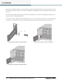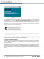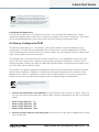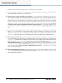
1
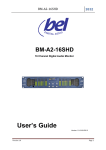
Quick Start and Field Reference Guide
Operation Manual
PLM™ Series
Powered Loudspeaker Management™ systems
Rev. 1.1.2
Item no. QSG-PLM Table of Contents
Table of Contents
2. Approvals�����������������������������������������������������������������������������������������������������������������������������������������������������4
3. Warnings������������������������������������������������������������������������������������������������������������������������������������������������������4
3.1 Explanation of Graphical Symbols�����������������������������������������������������������������������������������������������������������4
3.1.1 WARNING..........................................................................................................................................4
3.1.2 CAUTION...........................................................................................................................................4
3.2 Important Safety Instructions������������������������������������������������������������������������������������������������������������������5
3.3 User Responsibility���������������������������������������������������������������������������������������������������������������������������������5
3.3.1 Mains connection grounding.............................................................................................................5
3.3.2 Speaker output hazard......................................................................................................................5
3.3.3 Radio interference.............................................................................................................................6
3.3.4 Speaker damage...............................................................................................................................6
4. Welcome������������������������������������������������������������������������������������������������������������������������������������������������������7
4.1 Introduction����������������������������������������������������������������������������������������������������������������������������������������������7
4.2 Additional documentation�����������������������������������������������������������������������������������������������������������������������7
4.2.1 Lab.gruppen documents...................................................................................................................7
5. Installation���������������������������������������������������������������������������������������������������������������������������������������������������9
5.1 Unpacking������������������������������������������������������������������������������������������������������������������������������������������������9
5.2 Mounting�������������������������������������������������������������������������������������������������������������������������������������������������9
5.3 Rear Mounting�����������������������������������������������������������������������������������������������������������������������������������������9
5.4 Cooling�������������������������������������������������������������������������������������������������������������������������������������������������� 11
5.5 Operating Voltage���������������������������������������������������������������������������������������������������������������������������������� 11
5.6 Grounding���������������������������������������������������������������������������������������������������������������������������������������������� 12
6. Quick Start Tutorial���������������������������������������������������������������������������������������������������������������������������������� 13
6.1 Introduction ������������������������������������������������������������������������������������������������������������������������������������������ 13
6.2 Integrated Lake® Processing����������������������������������������������������������������������������������������������������������������� 13
6.3 Installing the Lake Controller Software������������������������������������������������������������������������������������������������� 13
6.3.1 Overview ........................................................................................................................................ 13
6.3.2 Software and Firmware Updates.................................................................................................... 14
6.3.3 Networked Applications.................................................................................................................. 15
6.4 How to Configure the PLM ������������������������������������������������������������������������������������������������������������������ 15
6.5 Gain Settings����������������������������������������������������������������������������������������������������������������������������������������� 19
6.6 Gain / Level Optimization����������������������������������������������������������������������������������������������������������������������20
7. Quick Guide Overview������������������������������������������������������������������������������������������������������������������������������22
7.1 Front Panel Overview����������������������������������������������������������������������������������������������������������������������������22
7.2 Rear Panel Overview����������������������������������������������������������������������������������������������������������������������������� 24
7.2.1 Input connectors and Links..............................................................................................................25
7.2.2 Output connectors..........................................................................................................................25
7.2.3 Network connectors........................................................................................................................26
2
PLM Series Quick Start and Field Reference Guide rev 1.1.2
Table of Contents
7.2.4 AC input...........................................................................................................................................27
8. Technical Specifications��������������������������������������������������������������������������������������������������������������������������28
9. Warranty����������������������������������������������������������������������������������������������������������������������������������������������������30
PLM Series Quick Start and Field Reference Guide rev 1.1.2
3
2. Approvals
2. Approvals
This equipment conforms to the requirements of the EMC Directive 2004/108/EC and the requirements of the Low
Voltage Directive 2006/95/EC.
Standards applied: EMC Emission EN55103-1, E3
EMC Immunity EN55103-2, E3, with S/N below 1% at normal operation level.
Electrical Safety EN60065, Class I
This equipment is tested and approved according to the U.S. safety standard ANSI/ UL 60065 and Canadian safety
standard CSA C22.2 NO. 60065. ETL made the tests and they are a Nationally Recognized Testing Laboratory
(NRTL).
3. Warnings
3.1 Explanation of Graphical Symbols
The lightning symbol within a triangle is intended to alert the user to the presence of un-insulated “dangerous voltages”
within the unit’s chassis that may be of sufficient magnitude to constitute a risk of electric shock to humans.
The exclamation point within a triangle is intended to alert the user to presence of important operating and service instructions in the literature accompanying the product.
3.1.1 WARNING
To reduce risk of fire or electric shock, do not expose this apparatus to rain or moisture.
Do not expose this system/apparatus to dripping or splashing and ensure that no objects filled with liquids, such as vases,
are placed on the apparatus.
L’appareil ne doit pas être exposé à des egouttements d’eau ou des éclaboussures et de plus qu’aucun objet rempli de
liquide tel que des vases ne doit pas être placé sur l’appareil.
This apparatus must be connected to a mains socket outlet with a protective earthing connection.
Cet appareil doi t être raccordé á une prise de courant qui est branchée à la terre.
The mains plug is used as a disconnect device and shall remain readily operable.
Lorsque la prise du réseau d’alimentation est utilisés comme dispositif de déconnexion, ce dispositif doit demeuré
aisément accessible.
3.1.2 CAUTION
To reduce the risk of fire or electric shock, do not remove screws. No user-serviceable parts inside. Refer servicing to
qualified service personnel
4
PLM Series Quick Start and Field Reference Guide rev 1.1.2
3. Warnings
3.2 Important Safety Instructions
Before using your PLM, be sure to carefully read the applicable items of this Quick Start and Field
Reference Guide and the Safety Instructions.
1. 2.
3.
4.
5.
6.
7. 8.
9.
10.
11.
12.
13.
14.
15.
16.
17.
18.
19.
Keep this guide for future reference.
Heed all warnings.
Follow all instructions.
Do not use this unit near water.
Do not spill water or other liquids into or on the unit. Do not operate the unit while wet or standing in liquid.
Clean only with dry cloth.
Do not block the air intake or exhaust ports. Install the unit in accordance with the instructions.
Do not operate the unit near heat producing devices such as radiators, heat registers, stoves or other apparatus that produce heat.
Always operate the unit with the chassis ground wire connected to the electrical safety earth. Do not defeat the safety purpose of
a grounding-type plug. A grounding-type plug has two pins and a third grounding prong. The third prong is provided for your safety.
If the provided plug does not fit into your outlet, consult an electrician for replacement of the obsolete outlet.
Connect only to AC power outlets rated 100-120 V or 200-240 V, 50-60 Hz as dictated by the unit’s voltage configuration.
Do not use this unit if the power cord is broken or frayed. Protect the power cord from being walked upon or pinched, particularly
at the plug and the point where it exits from the apparatus.
Only use accessories specified by the manufacturer.
The unit is intended to use in a 19” rack. Follow the mounting instructions. When a rack on wheels is used, use caution when
moving the loaded rack to avoid injury from tipping over.
Unplug this apparatus during lightning storms or when unused for long periods of time.
Do not connect the unit’s outputs in parallel or series with any other unit’s output. Do not connect the unit’s output to any other
voltage source, such as battery, mains source, or power supply, regardless of whether the unit is turned on or off.
Do not run any of the unit’s outputs back into another channel’s input.
Refer all servicing to qualified service personnel. Servicing is required when the apparatus has been damaged in any way such
as:
▸▸ Power-supply cord or plug is damaged.
▸▸ Liquid has been spilled into the unit
▸▸ An object has fallen into the unit
▸▸ The unit has been exposed to rain or moisture
▸▸ The unit does not operate normally
▸▸ The unit was dropped or the chassis is damaged
▸▸ Do not remove top or bottom covers. Removal of the covers will expose hazardous voltages. There are no user serviceable parts
inside and removal may void the warranty.
An experienced user shall always supervise this professional audio equipment, especially if inexperienced adults or minors are
using the equipment.
The mains plug is used as the disconnect device and shall remain readily accessible. If the mains plug is not readily accessible due
to mounting in a 19” rack, then the mains plug for the entire rack must be readily accessible.
The US National Differencescl.16.3 requires that network cables must be flame rated VW-1.
3.3 User Responsibility
3.3.1 Mains connection grounding
Your PLM must be connected to a grounded socket outlet.
3.3.2 Speaker output hazard
PLMs are capable of producing hazardous output voltages. To avoid electrical shock, do not touch any
exposed speaker wiring while the PLM is operating. The external wiring connected to the speaker
terminals shall be installed by a qualified person, or ready-made leads or cords of appropriate capacity shall
be used.
As the power output channels produce high voltage, do not connect or disconnect speaker cables
when the mains power is on.
PLM Series Quick Start and Field Reference Guide rev 1.1.2
5
3. Warnings
3.3.3 Radio interference
A sample of this product has been tested and complies with the limits for the European Electro Magnetic
Compatibility (EMC) directive. This equipment has also been tested and found to comply with the limits for a
Class B digital device, pursuant to Part 15 of the FCC Rules. These limits are designed to provide reasonable
protection against harmful interference from electrical equipment. This product uses radio frequency energy
and if not used or installed in accordance with these operating instructions, may cause interference to other
equipment, such as radio receivers. However, there is no guarantee that interference will not occur in a
particular installation.
If this equipment does cause harmful interference to radio or television reception, which can be determined
by turning the equipment on and off, the user is encouraged to try to correct the interference by one or
more of the following measures:
▸▸
▸▸
▸▸
▸▸
▸▸
Reorient or relocate the antenna.
Increase the separation between the equipment and receiver.
Connect the equipment to an outlet on a circuit different from that to which the receiver is connected.
Check if the affected unit complies with the EMC limits for immunity, (CE-labeled). If not, address the
problem with the manufacturer or supplier. All electrical products sold in the EC must be approved for
immunity against electromagnetic fields, high voltage flashes, and radio interference.
Consult the dealer or an experienced radio/TV technician for help.
3.3.4 Speaker damage
Your PLM Series device is very powerful and can be potentially dangerous to both loudspeakers and
humans alike. Many loudspeakers can be easily damaged or destroyed by overpowering them. Always
check the speaker’s continuous and peak power capabilities. Although the PLM’s attenuators can be used to
reduce the overall gain, an increase of the input signal can result in full output power, which may cause
damage to connected speakers.
3.3.5 Maintenance
For safe and reliable operation, the dust covers behind the front panel should be cleaned regularly. If the
dust filters are not maintained there will be safety risks. For example the unit can ignite the dust and a fire
will occur due to high internal temperatures. There is also a risk that the unit will malfunction since it is
dependent on constant airflow from front to rear. If the dust filters are not clean and the unit malfunctions,
any resultant problems will not be covered by the warranty.
6
PLM Series Quick Start and Field Reference Guide rev 1.1.2
4. Welcome
4. Welcome
4.1 Introduction
Thank you for choosing the Lab.gruppen PLM Series for your sound reinforcement needs. We are confident
that you will be pleased with the performance, unique features, configuration flexibility, reliability, and
long-term durability offered by PLM Series products.
This document provides a brief introduction to the features and functionality of the PLM Series of Powered
Loudspeaker Management systems. Please read through thoroughly to become acquainted with the basic
configuration and control options available in these products. Control and editing features are accessible
either via the intuitive front panel interface or remotely with the included Lake Controller software package.
In the following sections you’ll find the basic information needed to safely install a PLM system and place
it in service. We do, however, highly recommend reading through all of the product documentation on the
included CD-ROM in its entirety. As you become thoroughly familiar with the many configuration and control
options available in PLM Series products, you may learn about features and options that will affect your
choices of operational modes or loudspeaker system configurations.
The Lab.gruppen PLM Series incorporates proven Lake Processor technology and expands upon it, providing a suite of load verification and performance monitoring features. The power output section builds on
the foundation of the road-tested FP+ and legendary fP Series, providing the same powerful, tight bass
and transparent high frequency response. In addition, the PLM Series establishes new benchmarks for
high power and channel density in tandem with digital signal processing, system management, and unique
protection features.
The Lake Controller software contains system configuration, control, and monitoring features not available in
any other product. The key to these features is the LoadLibrary™, a comprehensive database that provides
a unique Fingerprint (load characteristic) for each loudspeaker model in the system. Using this data and
on-board DSP, LoadSmart™ then compares predicted response with actual system performance response
by applying a brief test signal. Any potential problems are identified instantly. During system use, SpeakerSafe™ monitors driver performance in real time to avoid power compression and provide detailed critical
information about system-wide driver performance.
Thank you again for placing your confidence in Lab.gruppen.
4.2 Additional documentation
This document, the PLM Series Quick Start and Field Reference Guide, serves as a basic introduction to
installation and operation of PLM Series Powered Loudspeaker Management systems. More detailed
information is available in the comprehensive PLM Series Operation Manual.
Also, if you intend to use the PLM Series unit(s) as part of networked systems, or access monitoring and
control features via the Lake Controller software application, then you may need to refer to the following
complementary documents. All are available on the included CD-ROM or online as noted.
4.2.1 Lab.gruppen documents
PLM Series Quick Start and Field Reference Guide rev 1.1.2
7
4. Welcome
The following documents are also available online at:
www.labgruppen.com/index.php/products/documentation/
PLM Series Operation Manual – A comprehensive guide to all operating features, including detailed information on use of the front panel interface, as well as a guide to digital audio signal distribution.
PLM Series Network Configuration Guide – This document provides detailed information on creating networks of PLM Series units, with sample network topologies and specific recommendations for third-party
networking devices.
Lake Controller User Manual PLM Addendum – This document covers those features and functions unique
to the PLM in the Lake Controller software application.
Dolby Lake Controller User Manual – This document provides detailed information on features and functions
of Lake Controller software, excepting those features unique to the PLM Series.
PLM Series Quick Start and Field Reference Guide – This document provides basic information needed to
unpack, install, and access basic feature sets of the PLM Series. A printed copy is included with your unit.
PLM Series Network Configuration Guide – This document provides detailed information on creating networks of PLM Series units, with sample network topologies and specific recommendations for third-party
networking devices.
All of the above are available both on the included CD-ROM or via download at:
www.labgruppen.com/index.php/products/documentation/.
8
PLM Series Quick Start and Field Reference Guide rev 1.1.2
5. Installation
5. Installation
5.1 Unpacking
Carefully open the shipping carton and check for any damage to the PLM Series product or the supplied
accessories. Every Lab.gruppen product is tested and inspected before leaving the factory and should arrive
in perfect condition. If any damage is discovered, please notify the shipping company immediately. Only the
consignee may initiate a claim with the carrier or their insurers for damage incurred during shipping. Save
the carton and packing materials for the carrier’s inspection.
In addition to the PLM, the shipping carton include the following items:
▸▸
▸▸
▸▸
▸▸
▸▸
PLM Series Quick Start and Field Reference Guide
AC mains lead (power cord)
Rear brackets for additional rack support (pair)
Mounting hardware for above
CD-ROM containing:
▸▸ Lake Controller software and firmware
▸▸ Release Notes
▸▸ Dolby Lake Controller User Manual
▸▸ Lake Controller User Manual PLM Addendum
▸▸ PLM Series Operation Manual
▸▸ PLM 10000Q Current Draw and Thermal Dissipation
▸▸ PLM Series Network Configuration Guide
▸▸ PLM 10000Q Technical Data
▸▸ PLM 14000 Technical Data
▸▸ PLM 10000Q A&E Specifications
We recommend that you keep the original carton and all other packaging materials to facilitate shipping of
the PLM should the need arise.
5.2 Mounting
Airflow for cooling the PLM is from front panel (intake) to rear panel (exit). There must be nothing at the front
or rear of the rack in which the PLM is mounted – such as doors or lids - to impede the airflow.
Note that there must always be sufficient space at the rear of the PLM to permit efficient air exit (see
section 5.4) and to accommodate rear connectors and cables; allowance must be made for cable or loom
bends within a rack. In particular, the mains cable (AC cord) and its Neutrik® PowerCon connector require at
least 120 mm (4.75 inches) clear rack depth behind the PLM rear panel. The PLM Series products have no
top or bottom vents; PLM’s may be stacked directly on top of each other. It may be desirable to include a 1U
spacer between PLMs to permit more convenient rear panel wiring.
5.3 Rear Mounting
Two rear support brackets, plus mounting hardware, are included with the PLM (figure 5.3a). It is recommended that these are used wherever possible. They should be fitted to vertical rack rails at the rear of the
rack. Refer to figures 5.3b and 5.3c for details of their installation.
PLM Series Quick Start and Field Reference Guide rev 1.1.2
9
5. Installation
Note that the support brackets are reversible and may be fitted to point either to the front or rear of the rack.
The orientation used in a particular situation will depend on the depth of the rack and the position of the rear
rack rails.
Two mounting methods are possible; note that the method shown in figure 5.3b additionally provides extra
security against unauthorized removal.
For situations where rapid removal and replacement of units is of paramount importance, the method shown
in figure 5.3c may be used as it does not involve any permanently secured fixing at the rear of the unit.
x2
x2
x2
x2
Figure 5.3a: Rear support mounting hardware
Figure 5.3b: Use washer for fixed installation
10
PLM Series Quick Start and Field Reference Guide rev 1.1.2
Figure 5.3c: Use tube for slide-on installation
5. Installation
5.4 Cooling
The PLM uses a forced-air cooling system with airflow from front to rear, allowing high continuous power
levels without thermal problems. (Front-to-rear airflow is preferable as air at the front of a rack is cooler
than that at the rear in nearly all situations.) Never attempt to reverse the airflow. The operation of the
PLM’s cooling system is dependent on front-to-rear airflow; it will not function effectively with airflow in the
opposite direction.
Make sure an adequate air supply is provided in front of the PLM, and that the rear of the PLM has sufficient
space to allow the exit air to escape. If the PLM is rack-mounted, never operate the unit with any front or
rear rack doors or covers in position. Also note that any unused rack spaces should have solid blanks fitted
(not ventilation blanks) to ensure efficient air circulation. Leaving gaps in between items of equipment
degrades the effectiveness of forced-air cooling.
If installing one or more PLM units in a rack with other fan-cooled equipment, be sure that all the other units
also use front-to-rear airflow for cooling. If this precaution is not observed, there is a risk of overheating, as
units with the reverse airflow will be drawing in air which has already been heated by the PLMs.
The PLM is equipped with a sophisticated temperature sensing system which protects it from any
overheating which may occur as a result of
inadequate ventillation. Should a power output
channel overheat, the temperature sensing circuits will mute
that channel until the temperature reduces to a safe level. If the
power supply overheats, another sensing circuit will mute will
reduce the overall output level of all channels in an effort to
bring the PSU temperature down. If a problem still exists, a
sensing circuit will mute the power output channel that has the
highest temperature reading, thereby reducing the overall
temperature of the power supply until it reduces to a safe
operating level.
Always make sure that the dust filters behind the detachable front panel are clean to ensure maximum
possible airflow.
5.5 Operating Voltage
The label adjacent to the mains (AC) input connector indicates the AC mains voltage for which the
amplifier is wired and approved. The amplifier is built in two versions: 115 V and 230 V. Connect the
mains cable (AC cord) only to an AC source of the voltage shown on the label.
Any damage resulting from a PLM Series product
being connected to an AC source of incorrect
voltage will not be covered by the warranty.
PLM Series Quick Start and Field Reference Guide rev 1.1.2
11
5. Installation
The PLM uses primary switching, which means the mains power is rectified on the primary side of the
transformer. This makes the power supply insensitive to mains frequency variation, and it will operate
normally on line frequencies from 45 to 75 Hz.
If the mains plug (AC plug) fitted to the mains cable (AC cord) is not appropriate for your country, it can be
removed and a locally-sourced one fitted instead, observing the color coding in the table below:
PowerCon Pin
230 V Version
115 V Version
L
Brown
Black
N
Blue
White
Green/Yellow
Green
Table 5.5: AC plug configuration
If you are not 100% confident of your competence to replace the mains plug (AC plug), the task should
be carried out by qualified personnel.
Once a suitable AC supply is connected, the PLM can be turned on using the front panel power switch.
When the unit is switched on, the PLM goes through a soft-start sequence as it performs a diagnostic
routine on the internal circuitry. The fans will run at high speed for a short period before dropping to idle
speed, and the power symbol in the power switch will change from red (Standby mode) to green (active).
In-rush current is controlled and limited during the
soft-start sequence, enabling multiple PLMs on the
same AC mains circuit to be powered up simultaneously.
5.6 Grounding
Analog inputs feature Iso-Float™ ground isolation, a technology which combines the benefits of transformercoupled isolation with the advantages of clean, direct-coupled inputs.
The audio converters are galvanically isolated, and not connected to the main ground. High-speed transformers and opto-isolators create a barrier between the PLM and the outside electrical environment.
The Iso-Float feature is activated by default, but
may be disabled via the supplied Lake Controller
software, or via the PLM’s front panel menu system.
In the interests of safety, NEVER disconnect the earth (ground) pin on the mains cable (AC power cord).
Use correctly-shielded balanced audio input connections to minimise hum and interference. Refer to section
10.2.1 for more information.
12
PLM Series Quick Start and Field Reference Guide rev 1.1.2
6. Quick Start Tutorial
6. Quick Start Tutorial
6.1 Introduction
This section covers installation of the Lake Controller software, input and output connections, basic functionality, and setup instructions. The information will allow a user to achieve a basic level of understanding of the
PLM Series system architecture while also setting up the unit for a basic system application.
A tutorial in section 6.4 takes you through the basic procedure for installing the software and setting up the
PLM for use with a “generic” professional sound system. Please refer to the documentation listed in section
4.2, which provides additional tutorials and instructional information on PLM features and functionality.
6.2 Integrated Lake® Processing
PLM Series products contain a fully integrated Lake loudspeaker management system, providing fullyprogrammable crossovers, EQ, dynamics and other functions. Primary control is via the supplied Lake
Controller software, although some functions can be accessed from the PLM’s front panel screen.
Setting up the integral Lake Processing via the Lake Controller software includes selecting the basic PLM
configuration, including input mixers, input format (analog or digital, etc.); crossover configuration; and
output routing.
A full description of Lake Controller software can be found in the Dolby Lake Controller User Manual and the
Lake Controller User Manual PLM Addendum. Please refer to an accompanying document, the PLM Series
Network Configuration Guide, for details of how to connect one or more PLMs to a PC via a network.
6.3 Installing the Lake Controller Software
6.3.1 Overview
The CD-ROM supplied with the PLM contains the Lake Controller software package. This should be
installed on any PC(s) that are to be used to control and monitor the PLM(s). In a situation where multiple
networked PLMs are involved, this will generally be a Tablet PC.
Minimum recommended computer specifications are:
1GHz or faster.
512 MB RAM or greater.
128 MB video RAM or greater.
Windows XP or Vista
DirectX® 8.1 or later (preinstalled with Windows XP).
100Base-T wired Ethernet adapter and/or 802.11 wireless Ethernet adapter.
When running large systems it is recommended to use a computer that well exceeds the minimum
specifications. If you are unsure about installing new software on a PC, please contact your organisation’s IT
department, or another suitably qualified specialist first.
PLM Series Quick Start and Field Reference Guide rev 1.1.2
13
6. Quick Start Tutorial
Figure 6.3: Lake Controller software installation screen
The Lake Controller software is easily installed by inserting the CD in the computer’s CD drive and allowing
the auto-setup routine to run. Select INSTALL then Lake Controller software from the installation window
to initiate installation. For most installations, the subsequent suggested default paths can be accepted.
Refer to section 2 of the Lake Controller User Manual for further details on how to install the software and
configure your computer for optimum performance.
Please note that, if pre-existing Lake Controller
presets are present on your PC when you install the
Lake Controller software, choosing a specific
installation path may be preferable. See the Lake
Controller User Manual PLM Addendum for more information.
Once the software is installed, the application can be launched by clicking the desktop icon created during
the install process in the usual way.
Full details of how to use the software application are contained in the documents Dolby Lake Controller
User Manual and Lake Controller User Manual PLM Addendum, both of which are supplied with the PLM. If
these documents are not available, see section 4.2 for download links.
6.3.2 Software and Firmware Updates
Lab.gruppen strive to improve and update the capabilities of PLM Series products. Many of these improvements are available to PLM Series users as free updates of the Lake Controller software application and
PLM Series firmware.
Registered users of PLM Series products will receive timely notification of firmware updates via e-mail. You
also may check for the most recent updates at www.labgruppen.com/index.php/support/software_firmware/. Complete information on firmware updates can be found in section 12.6 of the PLM Series Operation
Manual.
14
PLM Series Quick Start and Field Reference Guide rev 1.1.2
6. Quick Start Tutorial
Because of the time normally required for CD
preparation, as well as for shipment of the unit, it is
possible that the software and firmware on the
CD-ROM has been superseded by a newer version.
However, it is permissible to load the version on the CD and
then subsequently upgrade by downloading the newest
versions.
6.3.3 Networked Applications
The PLM Series implements a full Ethernet stack, and is a fully functional networked device. Control,
monitoring and digital audio (via the Dante™ network) are available via the Ethernet connections. For information on networked applications, please refer to the PLM Series Network Configuration Guide.
6.4 How to Configure the PLM
The following tutorial presents a “walk-through” of the steps involved in a typical loudspeaker system
configuration. It will allow the user to become familiar with the basic structure and operation of the PLM
Series implementation of Lake Processing. This tutorial employs the Lake Controller software, though some
steps are accessible via the PLM’s front panel.
The example given is for configuring a four-channel PLM to drive a 3-way loudspeaker system (with separate HF, MF and LF drivers), plus a separate Auxiliary output for feeding a subwoofer. It assumes that an
analog mixing desk is being used, and that a dedicated subwoofer output is being derived in the desk using
aux sends and a separate auxiliary output.
The example uses a generic (hypothetical) loudspeaker type to illustrate the principles involved. No speaker–
specific data or LoadLibrary Fingerprint is included in the crossover configuration. Also note that, for the
purposes of this tutorial, is is possible to connect small full-range cabinets as a test-setting, paying close
attention to steps 26-28 to avoid excessive power levels that could damage the loudspeakers.
The following tutorial assumes use of a Tablet PC
and therefore uses “tap” rather than “click” for
activating commands.
1. Connect the loudspeakers and subwoofer to the four power output channels as follows. Make sure
that you have correctly terminated your speaker cables on both the loudspeaker side and at the speaker
outputs.
▸▸
▸▸
▸▸
▸▸
Power Output Channel 1 – LF
Power Output Channel 2 – MF
Power Output Channel 3 – HF
Power Output Channel 4 – Sub.
2. Connect the main output of the mixing desk (either the left or right feed as appropriate) to Analog
input 1 of the PLM.
PLM Series Quick Start and Field Reference Guide rev 1.1.2
15
6. Quick Start Tutorial
3. Connect the subwoofer feed to Analog input 2 of the PLM.
4. Ensure the PLM is connected to a PC (via wired or wireless network connection) running the Lake
Controller software.
5. After ensuring that no audio is being output from the mixing desk, power up the PLM unit/s.
6. On the Tablet PC, launch the Lake Controller software application. On opening. a dialog box asks
whether a previous configuration should be restored. Tap No.
7. Tap the Modules button to open the horizontal scrolling bar.
8. In the scrolling bar, each connected PLM is represented with a frame that contains two discs. These are
labeled A and B and represent the A and B Lake processing modules in the PLM. Tap the frame and drag
both modules to the main part of the screen and tap again. The controller uploads the PLM’s settings and
the PLM is now ready to be controlled. If you have multiple PLMs connected, and hence multiple frames
in the scrollbar, observe the front panel of the PLMs. The PLM being tapped is indicated with a white LED
on the top left corner of the front panel.
9. Tap on Module A’s disc; its border will turn yellow.
10. Tap the Module Store/Recall in the button bar at the bottom of the screen. The contents of the scrolling
bar will change.
11. From the options offered in the scrolling bar, double-tap Default Modules; the scrolling bar contents
change again.
12. Double-tap the Contour Classic Crossovers folder in the scrolling bar. A set of loudspeaker symbols
will be displayed.
13. Tap CL3w + 1a, and then tap the Recall button. This reconfigures the DSP for the PLM’s Module
A as a 3-way crossover, plus a separate auxiliary channel. A dialog box will open asking if the data in
the destination module should be overwritten. Tap Yes. Another dialog box opens asking whether
Module B should be reconfigured. Tap either 2 Way or 2 Aux, as Module B will not be used in this
configuration.
14. Tap on Store/Recall EXIT to return to the Modules screen.
15. With Module A’s border still yellow (tap it if it isn’t), tap the I/O Config button at the bottom of the
screen to open the I/O Config screen.
16. The upper-right-hand pane depicts a block diagram of Module A. To the right of the red disc are blocks
representing the inputs to the 3-way crossover section. Tap on the Input 1 block to open the Input Mixer
control panel.
17. The control panel shows two faders for Inputs 1 and 2 to the left, and a bargraph meter showing the signal
level of the mixer output to the right. If the faders are not already so positioned, move Input 2’s fader
down until the button below the fader shows Input 2 OFF and turns red. Move Input 1’s fader up its
16
PLM Series Quick Start and Field Reference Guide rev 1.1.2
6. Quick Start Tutorial
scale until 0.00 dB is showing in the blue box at the top of the fader. Close the control panel by tapping
on the Return button.
18. The block diagram should now indicate that the 3-way crossover is fed from Input 1 only, at zero level.
Now note the small square block towards the bottom of the pane labeled Post EQ. This currently indicates
that the Auxiliary output channel (which will be output 4) is fed from the main crossover signal path. As
Analog Input 2 is being used for the subwoofer input, tap on the Post EQ block. This will change the
routing of the Auxiliary channel to receive its input directly from the Input Mixer and not post-EQ.
19. Tap on the lower Input 1 block (still in Module A’s pane) to open the Input mixer control panel for the
Aux channel. Move Input 2’s fader to the 0.00 dB position and tap on the Input 1 On/Off button (at
the bottom of the fader) so that it turns red. The block diagram will now show that the Auxiliary channel is
fed from Input 2 only, at unity gain. Tap the Return button to close the Aux Input Mixer window.
20. Note that Module B’s processing is not required in this configuration. Open Module B’s input mixer in
the same way as the previous steps, and make sure that both Input 1 and Input 2 are selected OFF.
21. Tap any of the four magnifying glass icons at the right-hand edge of Module A’s pane to open the
Output Configuration control panel. It is possible to reassign each of the four Module outputs to any of
the power output channels. To ensure that the PLM is set up in accordance with your original channel
allocation, check that the Output Configuration control panel looks like this:
Figure 6.4: Output configuration page
22. If the output assignments are not as shown, tap the Clear All Assignments button (“split arrows”) and
tap Yes to the warning dialog box. Then tap the numeric buttons to set the assignments as shown
in the screenshot above. Tap the return key to close the control panel and return to the I/O Config page.
23. The following settings in the left-hand pane should be made automatically by default:
▸▸
▸▸
▸▸
Digital Clock: Internal – 96 kHz
Input Configuration: Auto: Auto; Type: Analog; Offset/Headroom: 26 dBu
Dante Configuration: Dante Disabled
PLM Series Quick Start and Field Reference Guide rev 1.1.2
17
6. Quick Start Tutorial
▸▸
Analog Iso-Float & AES Termination: Inputs 1-2: Floating; AES: terminated.
24. If any of the settings differ from the above, please refer to the Dolby Lake Controller User Manual PLM
Edition Addendum for guidance on changing them.
25. The next step is setting the PLM’s gain structure. In a real situation, the loudspeaker manufacturer’s
data should be consulted for information regarding the relative drive levels, crossover specifications and
limiter settings for the LF, MF, HF and sub channels. Alternatively, a Lab.gruppen LoadLibrary file would
have been used that would already contain the necessary data to configure gain, crossover and limiter
settings. The default settings for the Lake Processing Module inputs and outputs are 0 dB, and for the
amplifier gain, 35 dB. We will assume that these settings are satisfactory for this illustration. From the
I/O Config screen, tap the Lab.gruppen Info button on the menu bar. The PLM Series Module Status
tab should open. If a different tab opens (the last accessed always opens), tap the Status tab to switch
to it.
26. The four fader strips displayed represent the four power output channels, as connected to the four Module
outputs in use. In accordance with the settings made in Output Configurations in Step 22, the four strips
represent Low, Mid, High and Aux respectively. The four faders are the amplifier attenuation controls. As
a precaution, move them all to the minimum position. Close the page with the Return button.
27. Tap on the Input Gain block in Module A’s pane. The left-most of the five faders now shown on-screen
is the Module input gain; the others are the Module output gains. For the purposes of our hypothetical
loudspeaker, set the Mid fader 6 dB below the Low fader and the High fader 12 dB below the Low
fader. The Module input is still muted. Un-mute it by tapping the Input Mute button (it turns blue).
Feed the PLM with audio by slowly opening fader(s) on the mixing desk. The bargraph meters on-screen
should indicate signals. Adjust the Module Input gain if necessary to obtain an appropriate signal level
on the output bargraphs. Close the page by tapping EQ/Levels EXIT on the menu bar. The I/O Config
screen will be displayed again.
28. Tap the Lab.gruppen Info button on the menu bar to return to the PLM Series Module Status tab. Now
we can increase the levels on attenuation faders carefully in order to drive signal into the output load.
Audio should now be heard.
18
PLM Series Quick Start and Field Reference Guide rev 1.1.2
6. Quick Start Tutorial
6.5 Gain Settings
The architecture of the PLM Series provides gain adjustments at a number of points in the signal flow path.
Thus, there are many places in which one can adjust the levels in the PLM. Each point serves a different
purpose.
More detailed information on gain settings can be found in the PLM Series Operation Manual section 8.1.
The following can be used as guidelines for adjustment of the gain settings, from input to output. The block
signal flow diagram below can also be used as a reference to help in understanding the signal path through
the PLM’s architecture:
Input headroom (Analog Inputs)
As a rule, this should be set to 12 dBu if the source is (or can be) limited to 12 dBu; otherwise it should be at
26 dBu. This setting has no direct influence on the rest of the gain stages in the PLM, or on the overall noise
floor. The PLM’s variable input gain is strictly meant to provide the appropriate headroom at the input stage.
(Adjust in I/O Config window, Input Configuration, left side.)
Input mixer
This setting should be left at “0” for most setups. If only one input channel is used, the other can be set to
“- inf”. (Adjust in I/O Config, module pane.)
Module output gain (Levels)
Two points of gain level adjustments are provided per Module output. They are used to balance the mutual
gain between frequency bands in a multi-way set up, and can be described as follows:
- Manufacturer gain: This is “hidden” within the module file and is set by the creator of the file. As such, it
is not user editable.
- User gain: This is editable by a user. The module file (part of the Fingerprint) contains a default value for
this as well as the manufacturer gain. If the manufacturer gain is set to a non-zero value, then the default
user gain is zero dB so that the user can easily see any changes that have been made to this setting. It
should normally not need to be adjusted by the user.
Output gain (Levels)
One adjustment is provided per output channel in the module to balance the mutual gain between frequency
bands in a multi-way set up. Generally, this setting is derived from the LoadLibrary Fingerprint data within
the PLM preset. As such, it should not need to be adjusted further. (Adjust in I/O Config, module pane.)
Attenuator
One adjustment is provided per output channel in the PLM. This control replaces the traditional knob found
on conventional amplifiers. It should typically be left at 0 dB during use. (Adjust in Lab.gruppen Info, Status
tab)
Amp Gain
Corresponds to the gain that you would have available in a conventional system if the amplifier section was
outside the PLM. It should retain the same settings as in the module file that is loaded. The limiter and
output gain settings in the output stage of the module were configured with this gain setting and will not
PLM Series Quick Start and Field Reference Guide rev 1.1.2
19
6. Quick Start Tutorial
be automatically compensated if changes are made. This configuration scheme, though unusual, allows for
backwards compatibility with other Dolby products. (Set in Lab.gruppen Info, Control tab.)
6.6 Gain / Level Optimization
Optimum setting of the PLM gain structure requires particular attention to two matters:
Make sure it can get loud enough.
To do this, the user should ensure that there is sufficient headroom in the signal path to avoid clipping
before you reach the limiters. At the same time, it must be possible to achieve enough gain through the
PLM to engage the limiters and realize a high average SPL as a consequence. As an optimal setting, allow
for a headroom of 10 dB or more for all channels. The simplest way to accomplish this is to increase the
input gain on the module.
Minimize the noise.
As a first step, use a digital input signal (AES or Dante) when possible. If using analog inputs, ensure that
headroom is not introduced on the input side that is unused or unreasonably high. If full power is not
required, or at least not a high average power, you may also lower the gain on the input of the module.
Figure 6.5: PLM Signal Flow Diagram (Part 1)
4
Output EQ
Module Output:
Gain/Level
Phase Rev
Mute
Output EQ
Module Output:
Gain/Level
Phase Rev
Mute
Output EQ
Module Output:
Gain/Level
Phase Rev
Mute
Output EQ
Module Output:
Gain/Level
Phase Rev
Mute
Output EQ
Module Output:
Gain/Level
Phase Rev
Mute
Output EQ
Module Output:
Gain/Level
Phase Rev
Mute
1
3
Input
Router
1
(Mute)
Analog 1/2
AES 1
AES 2
Dante X
Dante Y
Input
Router
2
(Mute)
Module:
Gain
Phase Rev
Mute
Input
Mixer A
EQ
Delay
Crossovers
2
Analog 1/2
AES 1
AES 2
Dante X
Dante Y
1
20
3
2
Input
Mixer B
Module:
Gain
Phase Rev
Mute
PLM Series Quick Start and Field Reference Guide rev 1.1.2
EQ
Delay
6. Quick Start Tutorial
Figure 6.5: PLM Signal Flow Diagram (Part 2) four power output channel model shown
4
Output EQ
Module Output:
Gain/Level
Phase Rev
Mute
LimiterMax
RMS / Peak
Output EQ
Module Output:
Gain/Level
Phase Rev
Mute
LimiterMax
RMS / Peak
Output EQ
Module Output:
Gain/Level
Phase Rev
Mute
LimiterMax
RMS / Peak
Output EQ
Module Output:
Gain/Level
Phase Rev
Mute
LimiterMax
RMS / Peak
Output EQ
Module Output:
Gain/Level
Phase Rev
Mute
LimiterMax
RMS / Peak
Output EQ
Module Output:
Gain/Level
Phase Rev
Mute
LimiterMax
RMS / Peak
Output Routing
5
6
Attenuator
Mute
Phase Rev
ISVPL
Amp Gain
LoadSmart
SpeakerSafe
AMP
Attenuator
Mute
Phase Rev
ISVPL
Amp Gain
LoadSmart
SpeakerSafe
AMP
Attenuator
Mute
Phase Rev
ISVPL
Amp Gain
LoadSmart
SpeakerSafe
AMP
Attenuator
Mute
Phase Rev
ISVPL
Amp Gain
LoadSmart
SpeakerSafe
AMP
PLM Series Quick Start and Field Reference Guide rev 1.1.2
21
7. Quick Guide Overview
7. Quick Guide Overview
5
4
8
10
3
1
2
6
7
9
11
PLM SERIES
12
2
1
Figure 7.1: PLM front panel layout
7.1 Front Panel Overview
The front panel controls, clustered around a 2.5” daylight readable LCD, perform most control and
monitoring functions via a simple menu system. The two switch clusters on either side of the LCD include
dedicated function keys as well as eight “soft keys” (functions vary according to current display page) and a
rotary data encoder.
Handles
Two sturdy metal handles are fitted to the front panel. The handles always should be used when carrying
the PLM, and when fitting it in or removing it from a rack. Ensure that any door or removable rack front
cover has sufficient depth to clear the handles.
Dust filters
Two dust filters are fitted behind metal covers. To remove the covers, loosen the thumbscrews located
behind the handles. Once detached, the dust filter elements can be removed for cleaning. See section 11.2
for information on cleaning the dust filters.
The device never should be operated without the
dust filters in place.
Display
The display illuminates when the PLM is active. Many of the control and metering functions found on
conventional amplifiers are replaced on the PLM by a set of on-screen pages which, together with the soft
keys and rotary encoder, allow monitoring and control of operating parameters. Multicolor LEDs embedded
in the soft keys display fault and warning status indications.
The layout of various display “pages” is standardized to a high degree for ease of use. In general, each page
is divided into two columns of four blocks, with the left-hand column referring to inputs and the right-hand
to outputs. Each block has four rows of data, which can be either alphanumeric or in the form of a bargraph
meter.
22
PLM Series Quick Start and Field Reference Guide rev 1.1.2
7. Quick Guide Overview
The brightness of the display and the adjoining network activity LED can be adjusted in the Frame page of
the Main menu.
Comprehensive details of the various display pages and the associated controls are given in section 9 –
Front Panel Interface.
Standby
The PLM is powered on and off by the top left-most button, STANDBY. See Lake Controller User Manual
PLM Addendum (sections 5.3.1 and 5.7) for further information regarding local and remote power control.
Mute Enable
Select MUTE ENABLE to allow muting via the soft function buttons of the inputs to the Lake system,
the power output channels, or both. The MUTE ENABLE legend in the button flashes when the mode is
selected. A second press will deselect the mode; however, if left active, MUTE ENABLE mode will automatically cancel after two minutes if no further mute actions are taken.
Meter
The METER button scrolls through four alternative views: HOME, MODULE, TEMPERATURE and INPUT.
Pressing METER when in MENU mode returns the screen to METER mode, and the HOME view is
displayed.
The display has two basic operating modes: METER
(default) and MENU.
Menu
Pressing the MENU button puts the screen display into MENU mode, and the “top” page of the MENU
“tree” is displayed. Once in MENU mode, the function buttons enable the user to navigate the menu tree
and access most PLM Series operating functions. See sections 9.12.2 to 9.12.8 for more details.
Soft Function Buttons
Eight soft function buttons are set adjacent to the display in two groups of four. These buttons are unlabelled
because their functions change according to the current menu mode as displayed on the screen. In MENU
mode they are used to navigate the menu tree and for the selection of parameters to edit. In METER mode
they will act in conjunction with the MUTE ENABLE feature.
Status LEDs
Eight tricolor LEDs are integrated into the soft function buttons for convenience. These convey both fault
and warning indications, plus the currently selected mute status of the Lake Processing system inputs and
the output channels. Full details can be found in section 9.10.
High-intensity LED
A white, high-intensity LED is located to the right of the display. This LED illuminates when the PLM Series’
control system is being accessed remotely via the Lake Controller software. Steady illumination of the white
LED indicates that the unit is selected in the Lake Controller software; a flashing white LED indicates a change
in parameters or operating state.
PLM Series Quick Start and Field Reference Guide rev 1.1.2
23
7. Quick Guide Overview
The brightness of the display and the adjoining network activity LED can be adjusted in the Frame page of
the Main menu.
Encoder
The rotary encoder is used to modify various PLM parameters (e.g. input level) in the leaf nodes of the
menu tree. When a menu item is selected that permits adjustment of parameter values, the ring around the
knob illuminates. While in HOME view the encoder can also be used to scroll through the different meter
views.
Exit
The EXIT key is used primarily while navigating the menu system in MENU mode; pressing it takes the
display back to a previous screen (“up one level” in the menu tree). In METER mode, pressing the EXIT key
always returns the display to the HOME view.
7.2 Rear Panel Overview
2
1
5
INPUT 1
SPEAKER OUTPUTS
2
1
LINK 1
INPUT 2
4
3
LINK 2
INPUT 1-2
7
LINK 1-2
ACT PRIM LINK
8
ACT
9
SEC
LINK
PLM 10000Q
200-240V
2500W
50-60Hz
CH 3
CH 1
CH 4
CH 2
ANALOG WITH ISO-FLOAT TM
PIN 1: SCRN 2: POS 3: NEG
SWITCHED 10/100 Base-TX
AES/EBU
CLASS 2 WIRING
Ser. N:o
Must be grounded/earthed
Made in Sweden
Removed!
SPEAKER OUTPUTS
INPUT 1
LINK 1
INPUT 2
INPUT 1-2
LINK 2
LINK 1-2
ACT PRIM LINK
ACT
SEC
LINK
PLM 10000Q
Figure 7.2a: 4-channel PLM
rear panel layout
200-240V
2500W
50-60Hz
6
ANALOG WITH ISO-FLOAT TM
CLASS 2 WIRING
1+/- CH 1+/2+/- CH 2+/-
Ser. N:o
1+/- CH 1+/2+/- CH 2+/-
3+/- CH 3+/4+/- CH 4+/-
PIN 1: SCRN 2: POS 3: NEG
SWITCHED 10/100 Base-TX
AES/EBU
1+/- CH 3+/2+/- CH 4+/-
Must be grounded/earthed
Made in Sweden
Removed!
2
1
5
INPUT 1
SPEAKER OUTPUTS
2
1
LINK 1
INPUT 2
4
3
LINK 2
INPUT 1-2
7
LINK 1-2
ACT PRIM LINK
8
ACT
9
SEC
LINK
PLM 14000
200-240V
2950W
50-60Hz
CH 2
CH 1
CH 2
CH 1
ANALOG WITH ISO-FLOAT TM
PIN 1: SCRN 2: POS 3: NEG
SWITCHED 10/100 Base-TX
AES/EBU
CLASS 3 WIRING
Ser. N:o
Must be grounded/earthed
Made in Sweden
Removed!
SPEAKER OUTPUTS
INPUT 1
LINK 1
INPUT 2
LINK 2
INPUT 1-2
LINK 1-2
ACT PRIM LINK
ACT
SEC
LINK
PLM 14000
Figure 7.2b: 2-channel PLM
rear panel layout
200-240V
2950W
50-60Hz
6
ANALOG WITH ISO-FLOAT TM
CLASS 3 WIRING
1+/- CH 1+/2+/- CH 2+/-
Ser. N:o
24
PIN 1: SCRN 2: POS 3: NEG
AES/EBU
SWITCHED 10/100 Base-TX
1+/- CH 2+/2+/- CH 1+/-
Removed!
PLM Series Quick Start and Field Reference Guide rev 1.1.2
Must be grounded/earthed
Made in Sweden
7. Quick Guide Overview
7.2.1 Input connectors and Links
See section 10 for full details of connector pinouts,
etc.
Analog inputs
Analog inputs are available on two standard XLR3F latching connectors. The inputs are electronically
balanced and feature Lake Iso-Float circuitry. The impedance is 20 kOhms, and the inputs can accept a
maximum input level of +26 dBu.
Analog links
Two latching XLR3M connectors are fitted adjacent to the analog input connectors. These are paralleled to
the input connectors to provide an unprocessed analog loop-through to feed additional PLM Series units, or
other equipment.
AES/EBU inputs
A latching XLR3F connector is provided which accepts an AES/EBU digital audio signal. Input
impedance is 110 ohms.
The AES/EBU digital audio format is two-channel,
and thus both PLM inputs are fed via a single
connector. Selection of the analog or digital inputs is
made via the front panel display or control software.
In comparison to analog signals, digital audio
signals such as AES/EBU require quite different
cabling and routing techniques. In particular,
standard XLR “mic cables” - even high-quality
ones - are rarely suitable for digital audio. Always use 110
ohm digital audio cables. See sections 10.2.2 and 12.5 for
further information before making any connections to the
AES/EBU inputs.
AES/EBU link
A latching XLR3M connector is fitted adjacent to the AES/EBU input connector. This is paralleled to the input
connector to provide an unprocessed AES/EBU loop-thru to feed further PLMs, or other equipment. An
AES/EBU 110 ohm termination load is enabled by default when the PLM is the last unit connected within an
AES/EBU daisy-chained system. The termination may be disabled, if desired, via the front panel menu and
within the Lake Controller software.
7.2.2 Output connectors
The PLM is available with a choice of connectors for power outputs: binding posts or Neutrik Speakon.
Bridge mode operation: The PLM is capable of
bridge-mode operation; however the present
system management software does not support
this mode and therefore bridged operation is NOT
recommended.
Please contact [email protected] for further information on bridge-mode operation.
PLM Series Quick Start and Field Reference Guide rev 1.1.2
25
7. Quick Guide Overview
Binding posts
In this version, the power outputs for loudspeaker connection are available on four separate pairs of fully
enclosed binding posts. (Channel configuration is model dependent)
Speakon connectors
The Speakon connector configuration differs on 2- and 4-channel PLM models. On 4-channel models, the
power outputs are simultaneously available on a single 8-pole Speakon connector, and on two 4-pole
Speakon connectors. The two 4-pole connectors carry the outputs of channels 1 & 2 and 3 & 4 respectively.
On 2-channel PLM models the two power output channels are available simultaneously on two 4-pole
Speakon connectors. Both connectors carry both channels. The second connector offers the channels in
reverse order. The table below shows the proper wiring scheme for these Speakon outputs.
Pin
No.
NL4 #1 Chs.
1&2
NL8 Chs.
1-4
NL4 #2 Chs.
3&4
1+
Ch. 1 o/p +
Ch. 1 o/p +
Ch. 3 o/p +
1-
Ch. 1 o/p -
Ch. 1 o/p -
Ch. 3 o/p -
2+
Ch. 2 o/p +
Ch. 2 o/p +
Ch. 4 o/p +
2-
Ch. 2 o/p -
Ch. 2 o/p -
Ch. 4 o/p -
3+
Ch. 3 o/p +
3-
Ch. 3 o/p -
4+
Ch. 4 o/p +
4-
Ch. 4 o/p -
Table 7.2.2a Speakon wiring and pinouts for 4-channel PLMs
Pin
No.
NL4 #1 Chs.
1&2
NL4 #2 Chs.
2&1
1+
Ch. 1 o/p +
Ch. 2 o/p +
1-
Ch. 1 o/p -
Ch. 2 o/p -
2+
Ch. 2 o/p +
Ch. 1 o/p +
2-
Ch. 2 o/p -
Ch. 1 o/p -
Table 7.2.2b Speakon wiring and pinouts for 2-channel PLMs
7.2.3 Network connectors
The two Neutrik RJ45 EtherCon® connectors permit integration into an Ethernet control network encompassing multiple PLM Series units as well as a PC running the Lake Controller software. Network connection permits full control of all PLM functions, and monitoring of all PLM operating parameters, from a remote
position. The PLM Series also supports the Dante audio networking protocol, which allows transmission of
multichannel, high-definition digital audio over the same Ethernet connection.
26
PLM Series Quick Start and Field Reference Guide rev 1.1.2
7. Quick Guide Overview
The Ethernet ports automatically switch to operate
at the two standard Ethernet data rates of 10Base-T
and 100Base-T, and also allow either “crossed” or
“straight” network cables to be used. Two LEDs
above each port indicate connection to a valid network (LINK)
and network activity (ACT).
Full information on how to connect the PLM to a network
is contained within a separate document, the PLM Series
Network Configuration Guide.
Primary connector
Use this connector when the network is a simple “star” configuration, consisting of individual Cat-5e
connections between PLMs and a local Ethernet switch. Alternatively it can be used to connect to the
Secondary connector of another PLM within a network, thus forming a daisy-chain topology.
Secondary connector
The secondary network connector can be used as a loop-through to daisy-chain multiple PLMs into the
network. Alternatively, system security can be greatly increased by using a dual-network topology. In this
case, the Secondary connector is connected to an alternative Ethernet distribution system employing a
second set of switches, thereby ensuring full redundancy and no single point-of-failure in the case that
Dante is used and a switch or cable fails. Further information on PLM network configurations can be found
in the PLM Series Network Configuration Guide.
When connecting multiple PLMs to an Ethernet
network, care must be taken NOT to create a ring
(closed loop) with the PLM Ethernet ports. Ethernet
by default will not support a ring topology; creating a
ring will cause the network to malfunction.
7.2.4 AC input
Mains connector
AC input to the PLM is via a Neutrik PowerCon connector, rated at 32 A.
PLM Series Quick Start and Field Reference Guide rev 1.1.2
27
8. Technical Specifications
8. Technical Specifications
PLM 14000
General
Number of input channels
Number of output channels
Peak total output all channels driven
Max. Peak output voltage per channel
Max. output current per channel
2
2
14000 W
193 V
90 A peak
Max. Output Power
All channels driven
Channel A, while channel B is driven at -3dB 2)
All channels driven into optimal impedance interval
2 ohms
7000 W
7500 W
> 7000 W into 1.8 – 2.1 ohms
Audio Performance
THD + N 20 Hz - 20 kHz for 1 W
THD + N at 1 kHz and 1 dB below clipping
Dynamic range with digital inputs (for all supported sample rates)
Dynamic range with analog inputs
Frequency response (1 W into 8 ohms, 20 Hz - 20 kHz)
Input Common Mode Rejection (CMR) 20 Hz to 1 khz
Internal sample rate
Internal data path
Product propagation delay, best case (96 kHz AES)
Product propagation delay, analog input
<0.05%
<0.04%
>114 dB
>112 dB
+ /-0.05 dB
>78 dB
96 k
32 bit floating point
1.61 ms
1.68 ms
Sample Rate Converters
THD + Noise
0.00003 %, 20 Hz - 20 kHz, unweighted
Analog to Digital inputs
THD + Noise
4 ohms
4300 W
4400 W
8 ohms
2300 W
2300 W
0.00022 %, typical at 1 kHz unweighted at +26 dBu headroom setting
0.00033 %, typical at 20 Hz and 20 kHz unweighted at +26 dBu headroom setting
AES / EBU inputs
Supported resolutions
Supported sample rates
≤24 bit
44.1, 48, 88.2, 96, 176.4, 192 kHz
Dante Audio Network
Supports redundant paths
Flexible topology
Network latency
Yes
Yes
0.8, 1.3 and 4 ms
Device presets
Local memory locations for the settings of the product
100
Limiters
Adjustable Inter-Sample Voltage Peak Limiter (ISVPL)
Current Peak Limiter < 300 ms
Current Average Limiter (CAL) > 300 ms
LimiterMax (rms and peak limiters)
– MaxRMS (rms voltage limiter)
– MaxPeak (peak voltage limiter)
17.8 - 193 V, step size 0.1 V
90 A peak
44 Arms
Yes
Yes
Gain
Amplifier gain
Analog attenuator
22 - 44 dB, step size 0.1 dB
-Inf to 0 dB, step size 0.25 dB
Back panel interface
AES / EBU / I/O (input + link)
Analog, 2-channel I/O (input + link)
Output connectors
Auto 10/100, Auto Uplink
Control and monitoring interface
Detachable mains cord
Cooling
2 x 3-pin XLR
4 x 3-pin XLR, electronically balanced
Neutrik Speakon (2 x NLT4) or 4 Binding Posts (pairs) (must be specified upon order)
2 x RJ45 EtherCon Auto 10/100, Auto Uplink
Via Ethernet for Lake Controller software
Neutrik PowerCon 32 A
Two fans, front-to-rear airflow, temperature controlled speed
Front-panel user interface:
Display, daylight readable LCD
Fault/Warning/Limit/Clip indicators
Mute and soft function buttons
Standby Power button
Mute Enable button
Meter button
Menu button
Rotary Encoder
Exit button
2.5 inch
RGB LEDs
8 provided
On/Off
Enables muting of outputs and inputs via soft-button keypad
Toggles through meter views
Provides a menu driven interface for full function front panel control
Yes
Provides a “back” function
Power
Operating voltage, 230 V / 115 V nominal
Soft start / Inrush Current Draw
Mains Power Average Limiter (PAL)
16 ohms
1150 W
1150 W
1)
140-265 V / 70-135 V (45 - 66 Hz)
Yes / max. 5 A
Yes
Dimensions (W/H/D)
Weight
Finish
W: 483 mm (19”), H: 88 mm (2 U), Overall D: 470 mm (18.5”) deep including handles and rear support.
13.5 kg (30 lbs.)
Black painted steel chassis with black painted steel / aluminum front
Approvals
CE, ANSI/UL 60065 (ETL), CSA C22.2 NO. 60065, FCC
Note 1): Separate 230 V or 115 V versions available. Not selectable on the product.
Note 2): Assymetrically loading the output channels (as shown, for example): If one channel has reduced output power requirements, the voltage drop from the power supply will be reduced,
resulting in a higher voltage and power output for the other channel.
All specifications are subject to change without notice.
Intercooler, Class TD and Lake are national and/or international registered trademarks of Lab.gruppen AB. PLM, Powered Loudspeaker Management, R.SMPS, LoadLibrary, LoadSmart,
SpeakerSafe and ISVPL are trademarks of Lab.gruppen AB. Dolby and the double-D symbol are registered trademarks of Dolby Laboratories. Contour, Mesa Quad EQ, Mesa Parametric EQ, Raised
Cosine Equalization, LimiterMax and Iso-Float are trademarks of Dolby Laboratories. Audinate is a registered trademark of Audinate Pty Ltd. Dante and Zen are trademarks of Audinate Pty Ltd.All
other trademarks remain the property of their respective owners.
Copyright © 2009 Lab.gruppen AB.
All rights reserved.
28
PLM Series Quick Start and Field Reference Guide rev 1.1.2
LAB.GRUPPEN AB ▸ SWEDEN
INTERNATIONAL CONTACT ▸ INFO@L ABGRUPPEN.COM
|
US & CANADA CONTACT ▸ [email protected]
www.labgruppen.com
Item no. TDS-PLM14000_V3
8. Technical Specifications
PLM 10000Q
General
Number of input channels
Number of output channels
Peak total output all channels driven
Max. Peak output voltage per channel
Max. output current per channel
2
4
10800 W
153 V
49 A peak
Max. Output Power
All channels driven
Channels A and B, while channels C and D are driven at -3 dB
All channels driven into optimal impedance interval
2)
2 ohms
4 ohms
2350 W
2300 W
2350 W
2400 W
> 2700 W into 2.4 – 3.2 ohms
Audio Performance
THD + N 20 Hz - 20 kHz for 1 W
THD + N at 1 kHz and 1 dB below clipping
Dynamic range with digital inputs (for all supported sample rates)
Dynamic range with analog inputs
Frequency response (1 W into 8 ohms, 20 Hz - 20 kHz)
Input Common Mode Rejection (CMR) 20 Hz to 1 khz
Internal sample rate
Internal data path
Product propagation delay, best case (96 kHz AES)
Product propagation delay, analog input
<0.05%
<0.04%
>116 dB
>114 dB
+ /-0.05 dB
> 78 dB
96 k
32 bit floating point
1.61 ms
1.68 ms
Sample Rate Converters
THD + Noise
0.00003 %, 20 Hz - 20 kHz, unweighted
Analog to Digital inputs
THD + Noise
8 ohms
1300 W
1300 W
16 ohms
660 W
660 W
0.00022 %, typical at 1 kHz unweighted at +26 dBu headroom setting
0.00033 %, typical at 20 Hz and 20 kHz unweighted at +26 dBu headroom setting
AES / EBU inputs
Supported resolutions
Supported sample rates
≤ 24 bit
44.1, 48, 88.2, 96, 176.4, 192 kHz
Dante Audio Network
Supports redundant paths
Flexible topology
Network latency
Yes
Yes
0.8, 1.3 and 4 ms
Device presets
Local memory locations for the settings of the product
100
Limiters
Adjustable Inter-Sample Voltage Peak Limiter (ISVPL)
Current Peak Limiter < 300 ms
Current Average Limiter (CAL) > 300 ms
LimiterMax (rms and peak limiters)
– MaxRMS (rms voltage limiter)
– MaxPeak (peak voltage limiter)
17.8 - 153 V, step size 0.1 V
49 A peak
25 Arms
Yes
Yes
Gain
Amplifier gain
Analog attenuator
22 - 44 dB, step size 0.1 dB
-Inf to 0 dB, step size 0.25 dB
Back panel interface
AES / EBU / I/O (input + link)
Analog, 2-channel I/O (input + link)
Output connectors
Auto 10/100, Auto Uplink
Control and monitoring interface
Detachable mains cord
Cooling
2 x 3-pin XLR
4 x 3-pin XLR, electronically balanced
Neutrik Speakon (1 x NLT8, 2 x NLT4) or 4 Binding Posts (pairs) (must be specified upon order)
2 x RJ45 EtherCon
Via Ethernet for Lake Controller software
Neutrik PowerCon 32 A
Two fans, front-to-rear airflow, temperature controlled speed
Front-panel user interface:
Display, daylight readable LCD
Fault/Warning/Limit/Clip indicators
Mute and soft function buttons
Standby Power button
Mute Enable button
Meter button
Menu button
Rotary Encoder
Exit button
2.5 inch
RGB LEDs
8 provided
On/Off
Enables muting of outputs and inputs via soft-button keypad
Toggles through meter views
Provides a menu driven interface for full function front panel control
Yes
Provides a “back” function
Power
Operating voltage, 230 V / 115 V nominal
Soft start / Inrush Current Draw
Mains Power Average Limiter (PAL)
1)
140-265 V / 70-135 V (45 - 66 Hz)
Yes / max. 5 A
Yes
Dimensions (W/H/D)
Weight
Finish
W: 483 mm (19”), H: 88 mm (2 U), Overall D: 470 mm (18.5”) deep including handles and rear support.
13.5 kg (30 lbs.)
Black painted steel chassis with black painted steel / aluminum front
Approvals
CE, ANSI/UL 60065 (ETL), CSA C22.2 NO. 60065, FCC
Note 1): Separate 230 V or 115 V versions available. Not selectable on the product.
Note 2): Assymetrically loading the output channels (as shown, for example): If one channel has reduced output power requirements, the voltage drop from the power supply will be reduced,
resulting in a higher voltage and power output for the other channel.
All specifications are subject to change without notice.
These
figures
are
accurate
atAB.the
of printing
but please
that allContour,
figures
are
subject
without
SpeakerSafe
and ISVPL are
trademarks
of Lab.gruppen
Dolbytime
and the double-D
symbol are registered
trademarks ofnote
Dolby Laboratories.
Mesa Quad
EQ, Mesa
Parametricto
EQ, change
Raised
Cosine Equalization, LimiterMax and Iso-Float are trademarks of Dolby Laboratories. Audinate is a registered trademark of Audinate Pty Ltd. Dante and Zen are trademarks of Audinate Pty Ltd.All
notice.
For
the
most
accurate
and
current
information
available,
please
visit
www.labgruppen.com/plm
other trademarks remain the property of their respective owners.
Intercooler, Class TD and Lake are national and/or international registered trademarks of Lab.gruppen AB. PLM, Powered Loudspeaker Management, R.SMPS, LoadLibrary, LoadSmart,
Copyright © 2009 Lab.gruppen AB.
All rights reserved.
PLM Series Quick Start and Field Reference Guide rev 1.1.2
29
9. Warranty
9. Warranty
General
This product is manufactured by Lab.gruppen, and it is warranted to be free from any defects caused by
components or factory workmanship, under normal use and service, for a period of six (6) years from date of
purchase from an authorized Lab.gruppen dealer.
If the product fails to perform as specified during the warranty period, Lab.gruppen will undertake to repair,
or at its option, replace this product at no charge to its owner, provided the unit is returned undamaged,
shipping prepaid, to an authorized service facility or to the factory.
This warranty shall be null and void if the product is subjected to: repair work or alteration by a person
other than those authorized by us; mechanical damage including shipping accidents; war, civil insurrection,
misuse, abuse, operation with incorrect AC voltage; incorrect connections or accessories; operation with
faulty associated equipment; or exposure to inclement weather conditions. Damage due to normal wear and
tear is not covered by the warranty. Units on which the serial number has been removed or defaced will not
be eligible for warranty service.
Lab.gruppen shall not be responsible for any incidental or consequential damages. Lab.gruppen’s responsibility is limited to the product itself. Lab.gruppen takes no responsibility for any loss due to cancellation of
any events, or rent of replacement equipment or costs due to a third party’s or customer’s loss of profit, or
any other indirect cost or losses however incurred.
Lab.gruppen reserves the right to make changes or improvements in design or manufacturing without
assuming any obligation to change or improve products previously manufactured.
This warranty is exclusive, and no other warranty is expressed or implied. This warranty does not affect the
customer’s statutory rights.
International warranties
Please contact your supplier or distributor for this information, as rights and disclaimers may vary from
country to country.
30
PLM Series Quick Start and Field Reference Guide rev 1.1.2
9. Warranty
Technical assistance and service
International
If your Lab.gruppen product requires repair, contact your Lab.gruppen dealer or distributor, or contact Lab.
gruppen by fax or email to obtain the location of the nearest authorized service centre.
Factory service
In the event Lab.gruppen product requires factory service, you may contact Lab.gruppen’s service department for return instructions and a Return Authorization number.
Please note for product return:
1. Use the original packing.
2. Include a copy of the sales receipt, your name, return address, phone and fax number, email address and
description of the defect.
3. Mark the Return Authorization number on the outside of the packing.
4. Ship the product prepaid to:
Lab.gruppen AB
Faktorvägen 1
SE-434 37 Kungsbacka
SWEDEN
Phone: +46 300 56 28 00
Fax: +46 300 56 28 99
[email protected]
www.labgruppen.com
Intercooler, Class TD and Lake are national and/or international registered trademarks of Lab.gruppen AB.
PLM, Powered Loudspeaker Management, R.SMPS, LoadLibrary, LoadSmart, SpeakerSafe and ISVPL are
trademarks of Lab.gruppen AB.
Dolby and the double-D symbol are registered trademarks of Dolby Laboratories. Raised Cosine Equalization, LimiterMax and Iso-Float are trademarks of Dolby Laboratories. Audinate is a registered trademark of
Audinate Pty Ltd. Dante and Zen are trademarks of Audinate Pty Ltd.
All other trademarks remain the property of their respective owners.
Copyright © 2009 Lab.gruppen AB. All rights reserved.
PLM Series Quick Start and Field Reference Guide rev 1.1.2
31
Operation Manual
L ab . gruppen A B ► S weden
internationa L contact ► info @ L abgruppen . com
U S & C A N A D A C O N T A C T ► info @ tc G - A M E R I C A S . com
www.labgruppen.com