1
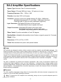
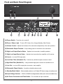
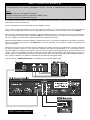
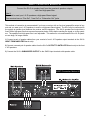
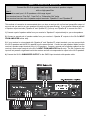
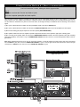
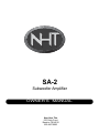
SA-2 Subwoofer Amplifier OWNER’S MANUAL Now Hear This 535 Getty Court Benicia, CA 94510 800-NHT-9993 IMPORTANT SAFETY INSTRUCTIONS CAUTION RISK OF ELECTRIC SHOCK DO NOT OPEN CAUTION: TO REDUCE RISK OF ELECTRICAL SHOCK, DO NOT REMOVE COVER (OR BACK). NO USER SERVICEABLE PARTS INSIDE. REFER TO QUALIFIED SERVICE PERSONNEL. The lightning flash with the arrowhead symbol, within an equilateral triangle, is intended to alert the user to the presence of uninsulated “dangerous voltage” within the product’s enclosure that may be of sufficient magnitude to constitute a risk of electric shock to persons. The exclamation point within an equilateral triangle is intended to alert the user to the presence of important operating and maintenance (servicing) instructions in the literature accompanying the appliance. WARNING: TO REDUCE THE RISK OF FIRE OR ELECTRIC SHOCK, DO NOT EXPOSE THIS APPLIANCE TO RAIN OR MOISTURE. 1. READ INSTRUCTIONS - All safety and operating instructions should be read before the appliance is operated. 2. RETAIN INSTRUCTIONS - Safety and operating instructions should be retained for future reference. 3. HEED WARNINGS - All warnings on the appliance and in operating instructions should be adhered to. 4. FOLLOW INSTRUCTIONS - All operating and use instructions should be followed. 5. WATER AND MOISTURE- The appliance should not be used near water - near bathtub, washbowl, kitchen sink, laundry tub; in a wet basement near a swimming pool, etc. 6. CARTS AND STANDS - Do not place this product on an unstable cart, stand, tripod, bracket, or table. The appliance should be used only with a cart or stand that is recommended by the manufacturer. 7. VENTILATION - The appliance should be situated so that its location and position do not interfere with proper ventilation. The appliance should not be situated on a bed, sofa, rug, or any surface that may obstruct cabinet openings. 8. HEAT - The appliance should be situated away from heat sources such as radiators, heat registers, stoves, or other devices (including amplifiers) that produce heat. 9. POWER SOURCES - This product should be operated only from the type of power source indicated on the marking label. If you are not sure of the type power supply in your home, consult your product dealer or local power company. For products intended to operate from battery power or other sources, refer to the operating instructions. 10. POWER CORD PROTECTION - Power supply cords should be routed so that they are not likely to be walked upon or pinched by items placed upon or against them, paying attention to cords and plugs, convenience receptacles, and the point where they exit from the appliance. 11. POLARIZED PLUG - This appliance is equipped with a polarized line plug (a plug having one blade wider than the other). This plug will fit into the power outlet only one way. This is a safety feature. If you are unable to insert the plug fully into the outlet, try reversing the plug. If the plug still fails to fit, contact your electrician to replace your obsolete outlet. Do not attempt to defeat this safety feature. 12. LIGHTNING - For added protection for this product during a lightning storm, or when it is left unattended and unused for long periods of time, unplug it from the wall outlet and disconnect the antenna or cable system. This will prevent damage to the product due to lightning and power line surges. 13. OVERLOADING - Do not overload wall outlets, extension cords, or integral convenience receptacles, as this can result in a risk of fire or electricshock. 14. CLEANING - Unplug this product from the wall outlet before cleaning. Do not use liquid cleaners or aerosol cleaners. Use a damp cloth for cleaning. 15. NON-USE PERIODS - This amplifier should be unplugged from the outlet when the appliance is left unused for a long period of time. 16. OBJECT AND LIQUID ENTRY - Never push objects of any kind into this product through openings, as they may touch dangerous voltage points or short-out parts that could result in a fire or electric shock. Never spill liquid of any kind on this product. 17. DAMAGE REQUIRING SERVICE - The appliance should be serviced by qualified personnel when: a. The power supply cord or plug has been damaged; or b. Objects have fallen on or liquid has been spilled into the appliance; or c. The appliance has been exposed to rain; or d. The appliance does not appear to operate normally or exhibits a marked change in performance; or e. The appliance has been dropped or the enclosure is damaged. 18. SERVICING - Do not attempt to service this product yourself, as opening or removing covers may expose you to dangerous voltage or other hazards. Refer all servicing to qualified service personnel. For service warranty information call the NHT Hotline number: 1-800-NHT-9993. 19. REPLACEMENT PARTS - When replacement parts are required, be sure the service technician has used replacement parts specified by the manufacturer or that have the same characteristics as the original part. Unauthorized substitution may result in fire, electric shock, or other hazards. 20. SAFETY CHECK - Upon completion of any service or repairs to this product, ask the service technician to perform safety checks to determine that the product is in proper operating condition. CAUTION TO PREVENT ELECTRIC SHOCK, DO NOT USE THIS (POLARIZED) PLUG WITH AN EXTENSION CORD, RECEPTACLE OR OTHER OUTLET UNLESS THE BLADES CAN BE FULLY INSERTED TO PREVENT BLADE EXPOSURE. Table of Contents I. Specifications Placement Front and Back Panel Diagrams General Connections Low-Pass Filter High-Pass Filter Subwoofer Phase Subwoofer Volume Control 2 2 3 4 4 4 4 5 II. The SA-2 and SW2Si: The SW2Pi Powered Subwoofer System Connection Methods Fine Tuning the Subwoofer 5 10 III. Multiple Subwoofer Configurations: Using two SW2Si subwoofers Connection Method 11 11 IV. The SA-2 and Biamplification Connection Methods Recommended Biamplification Settings Bass Tuning Methods 11 12 15 15 V. Operation Maintenance Changing the Line Voltage Setting Changing the Fuse Troubleshooting Glossary of Terms 15 15 15 15 16 16 VI. Warranty Information 17 Thank you for your purchase of the NHT SA-2 monaural subwoofer amplifier. Please take a few moments to read through this Owner’s Manual prior to installing your new amplifier and/or subwoofer system. The information provided can help you to obtain maximum performance from your audio system. For your convenience, a glossary on page 16 explains some technical terms. If you have questions or require assistance at any time during the installation or operation of your new amplifier/powered subwoofer system, please call your local NHT dealer or our Toll-Free Customer Service Hotline at: 1-800-NHT 9993 Please retain the SA-2 packaging to protect the amplifier in the event that you move or transport it. 1 SA-2 Amplifier Specifications · System Type: Monaural Class G subwoofer amplifier · Power Output: 120 watts RMS into 8 ohms, 165 watts into 4 ohms · Frequency Response: 25Hz - 150Hz +/-3dB · Distortion: Less than 0.03% at full power · Crossover: Low-pass continuously variable between 35-150Hz, 18dB/octave Selectable high-pass at 50, 75, and 110Hz, 12dB/octave (line-level) Fixed high-pass at 100Hz (8 ohms), 6dB/octave (high-level) · Input Connectors: Gold plated RCA jacks for line level input Gold plated barrier strip for speaker level input · Output Connectors: Gold plated RCA jacks for line level output Gold plated barrier strip for speaker level output Gold plated 5-way binding posts for subwoofer output · Phase Control: 2 position selectable at 0 and 180 degrees · Standby Mode: (defeatable) Automatically shuts off when no signal is present for 10 minutes · Weight: 15 lbs. · Dimensions: 3.75"H x 16"W x 10.75"D · Finish: Black anodized front panel, black painted chassis Design NHT products are designed to deliver refined, musical sound from attractive and affordable packages. Our efforts are guided by the study of human hearing and are optimized for real-world use. Every NHT product undergoes rigorous testing and quality control at the factory to ensure you years of listening pleasure. The NHT SA-2 Subwoofer Amplifier is a powerful and versatile monaural low frequency amplifier. The SA-2 and SW2Si passive subwoofer together comprise the SW2Pi Powered Subwoofer System. Additionally, the SA-2 is designed to power the subwoofer sections of NHT tower speakers when connected in biamplified configurations. The SA-2 is optimized for powerful low frequency reproduction, with a host of convenience features and sufficient high output capability to drive up to two subwoofers. Its discrete Class G design enables cooler operating temperatures, employing a massive power transformer and dual-rail power supplies for high output and low distortion. Only high-precision, low-noise componentry is used in the crossover circuits, for seamless blending with any loudspeaker. Placement The SA-2 amplifier’s stand-alone design allows it to be placed either with other electronic components in the system or on top of the SW2Si subwoofer enclosure. Note: To prevent the SA-2 amplifier from overheating, always be sure to provide adequate space for proper ventilation. 2 Front and Back Panel Diagram (A) Power Switch - Turns the unit on and off (B) Power / Status Light - Tri-color LED: Green (On), Orange (Standby), Red (Protect) (C) Volume Control - Adjusts the loudness of the subwoofer independently of the main speakers (D) Subwoofer Output Terminal - 5-way binding posts for connection to the subwoofer (E) High Level Output Barrier Strips - Speaker level connection to satellite speakers (F) High Level Input Barrier Strips - Speaker level connection from amplifier or A/V receiver (G) Line In - Low level RCA input jacks (H) Low-Pass Filter (Subwoofer Fc) - Continuously variable low-pass crossover control (I) High-Pass Filter (Satellite Fc) - 3-way selectable high-pass crossover for satellite line out (J) Line Out - Low level RCA output jacks to receiver / main amplifier (K) Subwoofer Phase Selector - 2-position selectable phase control (L) Standby Mode Switch - Selects standby mode on or off. Status LED shows orange in standby mode (M) Input Voltage Selector - 115VAC or 230VAC line voltage selector switch (note: under a removable cover) (N) AC Power Connection and Fuse Holder - For universal line input connection 3 General Connections Caution: Prior to connecting the SA-2 to your system, it is important that all AC power connections to associated components (receivers, amplifiers, pre-amplifiers, processors, etc.) are either unplugged or turned off. Do not plug in or connect the SA-2 to AC power until all connections have been made. The SA-2 subwoofer amplifier is designed for use with passive subwoofers only. As it is not a full-range amplifier, it will not function satisfactorily if used to power full-range loudspeakers. Four different subwoofer connection methods are covered in this manual. Proper wiring of the subwoofer is essential to good sound. At a minimum, 14 AWG cable is recommended for runs of 15 feet or less between the SA-2 and the subwoofer, with heavier special purpose cable used for longer runs. For specialty cable considerations, consult your local authorized NHT retailer. If you are using a single SA-2 to drive two SW2Si subwoofers in parallel, it is preferable to use similar lengths of speaker cable for connections to each subwoofer. Prepare your speaker cable by removing 1/4” to 3/8” of insulation from the ends and twisting the exposed wire strands tightly. The fiveway binding posts on the subwoofer and amplifier will accept raw wire, banana plugs or spade plugs. Tighten the binding posts by hand, as pliers can strip or break them. Be sure to wire the subwoofer “in-phase.” That is, the positive (red) terminal on the amplifier output must be connected to the corresponding positive (red) terminal on the subwoofer. Likewise with the negative (black) terminals. All speaker cables have some sort of marking along one or both conductors to help you make the correct connections. To minimize noise pickup, segregate cables by function. Do not run low level signal cables parallel to power cables, speaker cables, or digital cables. Also, do not run speaker cables or digital cables parallel to power cords or parallel to each other. If different types of cables are placed near each other at some place in your system, separate them by the maximum practical distance and cross them at right angles where they meet. Low-Pass Filter (Subwoofer Fc) The SA-2 features a continuously variable LOW-PASS FILTER which is used to determine the range of frequencies that the subwoofer will reproduce. For example, a low-pass setting of 100Hz means that the subwoofer reproduces only frequencies below 100Hz. The Low-Pass Filter is variable between 35Hz (low bass) to 150Hz (upper bass), to accommodate a variety of speaker configurations. If you are using Connection Method #1 or #4, your main speakers are reproducing the entire frequency range (including bass) and it is advantageous for the subwoofer to reproduce only those frequencies below the rated response of the main speakers. For example, if your main speakers have a rated low frequency response of 60Hz, begin with the Low-Pass Filter set at 60Hz. See the “Fine Tuning” section for further adjustment guidelines. If you are using Connection Method #2, your main speakers are reproducing only the frequency range selected by the SA-2’s HighPass Filter (see following section). As a starting point, set the Low-Pass Filter at about the same frequency you have set the High-Pass Filter. For example, if the High-Pass Filter sends only signals above 75Hz to your main speakers, begin with the Low-Pass Filter set at 75Hz. See the “Fine Tuning” section for further adjustment guidelines. If you are using Connection Method #3, your main speakers are reproducing only frequencies above 100Hz, due to the fixed 100Hz high-pass filter at the speaker-level output barrier strip. As a starting point, set the Low-Pass Filter at 100Hz. See the “Fine Tuning” section for further adjustment guidelines. High-Pass Filter (Satellite Fc): Connection Method #2 Only The SA-2 features a 3-position selectable HIGH-PASS FILTER which is used to determine the range of frequencies that the L & R speakers (“satellites”) will reproduce. For example, a high-pass setting of 50Hz means that the L & R speakers receive a signal containing only frequencies above 50Hz. The benefit of high-pass filtering is improved dynamic range and lower distortion in the main speakers, as they are spared the task of low frequency reproduction. There are three available high-pass settings: 50Hz, 75Hz and 110Hz. The High-Pass Filter should initially be set to a frequency above the rated low frequency limit of the L & R speakers. For example, if your speakers have a rated low frequency response of 40Hz, use the 50Hz high-pass setting. If your speakers have a rated low frequency response of 90Hz, use the 110Hz high-pass setting. To select the appropriate high-pass setting for your L & R speakers, check the owner’s manual for their rated low frequency response. If you are unable to obtain this information, here are some common high-pass settings: Subwoofer Phase Small speaker 100Hz to 150Hz Medium speaker 80Hz to 100Hz Large speaker 65Hz to 80Hz The ability to adjust subwoofer phase is a great advantage for achieving smooth bass response in your system. The propagation of low frequency sound waves from the subwoofer and the speakers combined can sometimes cause peaks and dips in the frequency response at the listening position. In this case, adjusting the subwoofer phase may improve the blending and overall performance of the system. The SA-2 features a 2-position SUBWOOFER PHASE selector which inverts the phase of the subwoofer between the 0° position (normal phase) and the 180° position (reverse phase). The optimal phase setting will differ according to room conditions and placement, and the main speakers used. Experiment with phase settings by listening to a familiar CD from the listening seat, alternating phase set- 4 tings on the same track. Do not attempt to evaluate the best sound while standing above the subwoofer or amplifier, as the sound at the listening position will be significantly different. Subwoofer Volume Control The SA-2’s front panel VOLUME CONTROL allows you to adjust the volume of the subwoofer relative to the rest of the system. Many listeners make the mistake of setting subwoofers too loud, which can cause excess bloat and loss of detail and musicality. A properly calibrated subwoofer blends in with the speakers and does not call attention to itself. Observe the following guidelines for volume setting: Turn down the volume control of the SA-2 to its lowest position (counter-clockwise). Turn on your system, including the SA-2. Play some music you are familiar with and set your receiver/preamplifier volume to a comfortable listening level. Slowly increase the volume on the SA-2, listening for proper frequency balance. When the subwoofer output is balanced with the rest of the system, you will hear improved bass extension, but you should be unaware that it is coming from the subwoofer! From this point on, the volume control on your receiver/preamplifier will control the overall volume of your system, including the subwoofer. The SA-2 and SW2Si: The SW2Pi Powered Subwoofer System A subwoofer’s performance in the context of your audio / video system is highly dependent upon its interaction with your front L & R speakers. Since a subwoofer is designed only to provide low frequency response, it is important to connect it in a manner that ensures seamless integration with your speakers. There are four possible connection methods outlined in this manual. The best method for you depends on the size of your front L & R speakers and the connection options available on your receiver or preamplifier. To help you determine the best way to connect the subwoofer to your system, consider the following suggestions: 1. If you have large (full-range) L & R speakers... 1st Choice: Method #2 (SA-2 connected at line level with high-pass filter loop) 2nd Choice: Method #1 (SA-2 connected at line level, no high-pass filter) 3rd Choice: Method #4 (SA-2 connected at speaker level, no high-pass filter) If your L & R speakers have generous bass response and you are adding a subwoofer, you have the option of sending the speakers a high-pass filtered signal (Method #2). With the low bass information removed from the signal before it reaches the speakers, all low frequencies are reproduced exclusively by the subwoofer. With this configuration it is usually easier to achieve smooth low frequency response, as the subwoofer reproduces a different frequency range than the speakers. Use the 50Hz high-pass setting. If you want to run the L & R speakers full-range, or if you have a receiver with no “Pre-Out” and “Main-In” (see “What connection methods are available?” below), you can run the L & R speakers full range and use the subwoofer only to provide low bass reinforcement (Connection Methods #1 and #4). Sending the speakers a full-range signal can sometimes make it difficult to integrate them with the subwoofer, as their combined low frequency output can cause irregularities (peaks and dips) in the room’s low frequency response. In this case, the subwoofer’s low-pass setting should be quite low and used only to fill in the lowest octave. Method #3 is not recommended with large L & R speakers. 2. If you have small (bookshelf) L & R speakers... 1st Choice: Method #2 (SA-2 connected at line level with high-pass filter loop) 2nd Choice: Method #3 (SA-2 connected at speaker level with fixed high-pass filter) If your L & R speakers are smaller bookshelf-type models with limited bass response, it is advisable to send them a high-pass filtered signal (Method #2 or #3). With the low bass information removed from the signal before it reaches the speakers, all low frequencies are reproduced exclusively by the subwoofer. The L & R speakers exhibit reduced distortion, greater dynamic range and power handling, because they receive a signal containing only information that falls within their specified frequency response range. Use the 75Hz or 110Hz high-pass setting. Alternately, you can run the speakers full range and use the subwoofer to reproduce all the low bass frequencies below their response capabilities (Methods #1 and 4). While simple, this configuration does not remove the burden of low frequencies from the L & R speakers and may limit their output at higher volumes. 3. What connection options are available? a) If you are using a separate preamplifier and main amplifier, all of the connection methods are available to you. b) If you are using an integrated amplifier or receiver (hereafter called “receiver”) with “Pre-Out” and “Main-In” jacks, all of the connection methods are available to you. c) If you are using a receiver with “Pre-Out”, “Line Out’ or “Subwoofer Out” jacks but no “Main-In” jacks, you may use Methods #1, #3 or #4. d) If you are using a receiver with no “Pre-Out”, “Line Out” or “Subwoofer Out” jacks, you may use Methods #3 or #4. 5 SW2Pi Connection Method #1 Connect the SA-2 from a receiver / preamplifier’s “Pre-Out”, “Line Out” or “Subwoofer Out,” with no high-pass filtering Use if: You wish to run your L & R speakers full-range You have a receiver with “Pre-Out” jacks but no “Main-In” jacks You have a receiver with “Subwoofer Out” jacks This method of connection allows your main speakers to receive the full-range audio signal (no high-pass filtering), and the subwoofer to be utilized for low bass extension only. 1) Your L & R speakers are connected directly from your amplifier / receiver. 2) If you have a receiver with “Pre-Out” (or “Line Out”) jacks but no “Main-In,” you may connect the SA-2 to the “Pre-Out” without having to route the signal back into the receiver. Using an RCA interconnect cable, connect the “Pre-Out” to the SA-2’s LINE IN. 2a) If you have a separate preamplifier and amplifier, and the preamplifier has two pairs of “Line Out” jacks, connect one pair directly to your main amplifier, and the second pair to the SA-2’s LINE IN. If your preamplifier has only one pair of “Line Out” jacks, you may utilize two “Y”-splitters to send the line-level signal into both the main amplifier and the SA-2. 3) Many integrated amplifiers and receivers feature a “Subwoofer Out” jack. If your receiver’s “Subwoofer Out” consists of a single RCA jack, you may plug it into either the left or right LINE IN jack on the SA-2. Alternately, you may utilize a “Y”-splitter to split the line-level signal into both jacks. 3a) Check your receiver’s owner’s manual to see if the “Subwoofer Out” signal is full-range or low-pass filtered. A full range “subwoofer out” signal is preferred, however on many receivers the “Subwoofer Out” signal is low-pass filtered to cut out frequencies above a certain point (80Hz, for example), which means the signal coming out this jack has already passed through an internal crossover in the receiver. This can be problematic, because the signal will encounter further low-pass filtering when passing through the SA-2. If possible, bypass any low-pass filtering contained in the “Subwoofer Out” signal, as the SA-2 will provide greater flexibility of adjustment. If the receiver’s “subwoofer out” signal has a selectable low-pass filter, select the highest setting. 4) Connect the SA-2 SUBWOOFER OUTPUT to the SW2Si input terminals with speaker cable. SW2Pi Connection Method #1 6 SW2Pi Connection Method #2 Connect the SA-2 between a receiver’s “Pre-Out” and “Main-In”, with high-pass filter loop Use if: You wish to send your L & R speakers a high-pass filtered signal You have a receiver with “Pre-Out” and “Main-In” jacks You have a separate preamplifier and main amplifier This method allows your main speakers to receive a high-pass filtered signal (not full range), and the subwoofer to be utilized for low- to mid-bass reproduction. The full-range line-level signal coming from the receiver’s “Pre-Out” passes through the SA-2’s selectable high-pass filter, which removes the low frequencies from the signal before sending it back to the receiver’s “Main-In.” This configuration effectively increases the receiver and speakers’ dynamic range and power output by sparing them the difficult task of reproducing low frequency information. 1) Your L & R speakers are connected directly from your amplifier / receiver. 2a) If you have a receiver with “Pre-Out”and “Main-In” jacks, patch in the SA-2 between these. With an RCA interconnect cable, connect the receiver’s “Pre-Out” to the SA-2’s LINE IN. Connect a second RCA interconnect cable from the SA-2’s SATELLITE LINE OUT back to the receiver’s “Main-In.” 2b) If you have a separate preamplifier and main amplifier, connect the preamplifier output to the SA-2’s LINE IN. Connect a second interconnect cable from the SA-2’s SATELLITE LINE OUT to the main amplifier’s line-level inputs. With this configuration, your preamplifier is not connected directly to your amplifier; instead the signal passes through the SA-2 before it reaches the amplifier. 3) Connect the SA-2’s SUBWOOFER OUTPUT to the SW2Si input terminals with speaker cable. SW2Pi Connection Method #2 7 SW2Pi Connection Method #3 Connect the SA-2 at speaker level from the receiver’s speaker outputs, with fixed high-pass filter Use if: You wish to send your L & R speakers a high-pass filtered signal Your receiver has no “Pre-Out”, “Line Out” or “Subwoofer Out” jacks This method of connection is recommended if you have a receiver with no line level preamplifier output of any sort and you want your L & R speakers to receive a high-pass filtered signal. The SA-2 may be connected to the system at speaker level between the receiver and the speakers. The SA-2’s speaker-level output has a fixed 100Hz high-pass filter that removes frequencies below 100Hz before sending the signal on to the speakers. The speaker-level high-pass filter is not adjustable. This method is not recommended if the L & R speakers are large, full range models. 1) Connect a pair of speaker cables from your receiver’s front L & R speaker output terminals to the SA-2’s INPUT FROM AMPLIFIER barrier strip. 2) Connect a second pair of speaker cables from the SA-2’s OUTPUT TO SATELLITES barrier strip to the front L & R speakers. 3) Connect the SA-2’s SUBWOOFER OUTPUT to the SW2Si input terminals with speaker cable. SW2Pi Connection Method #3 8 SW2Pi Connection Method #4 Connect the SA-2 at speaker level from the receiver’s speaker outputs, with no high-pass filter Use if: You wish to send your L & R speakers a full range signal Your receiver has no “Pre-Out”, “Line Out” or “Subwoofer Out” jacks Your receiver has two sets of speaker output terminals: “Speaker A” and “Speaker B” This method of connection is recommended when you have a receiver with no line level preamplifier output of any sort and you want to run your speakers full range (no high-pass filtering). If your receiver features two sets of speaker output terminals (“Speaker A” and “Speaker B”), you may use “Speaker B” to connect the SA-2. 1) Connect a pair of speaker cables from your receiver’s “Speaker A” outputs directly to your main speakers. 2) Connect a second pair of speaker cables from your receiver’s “Speaker B” outputs to the SA-2’s INPUT FROM AMPLIFIER barrier strip. 3) If your receiver is not equipped with “Speaker A” and “Speaker B” output terminals, you may connect both the L & R speakers and the SA-2 in parallel from the same terminal. Connect one pair speaker cables from the receiver’s speaker output terminal to the L & R speakers. Connect a second pair of speaker cables from the receiver’s same output terminal to the SA-2’s INPUT FROM AMPLIFIER barrier strip. The SA-2’s barrier strip input will not present a significant load to the receiver and will not compromise its output to the L & R speakers. 4) Connect the SA-2’s SUBWOOFER OUTPUT to the SW2Si input terminals with speaker cable. SW2Pi Connection Method #4 9 Fine Tuning the Subwoofer The frequency chart below lists some terms commonly used to describe different bands of the frequency spectrum. The key to good subwoofer / speaker integration is repeated listening, followed by small re-adjustments of the subwoofer controls. The most important bass tuning functions you will control are the LOW-PASS FILTER, followed by the VOLUME CONTROL settings and then PHASE SELECTOR. Frequency Chart Low Bass Mid Bass Upper Bass Below 50Hz 50Hz-100Hz 100Hz-180Hz Lower Mid Mid 180Hz-300Hz Upper Mid High 700Hz-3K 3K and above 300Hz-700Hz Listen to your system and make adjustments to achieve a seamless blend between your main speakers and the SW2Pi. Four common problems are outlined below. Follow the flow chart to correct these. See the glossary for any terms you are unfamiliar with. Fine Tuning Flow Chart Problem Solution Too much mid / upper bass: “Boomy” Lower lowpass crossover frequency Lower subwoofer volume Lacks low bass weight Excessive low bass weight Increase subwoofer volume and lower lowpass setting Decrease subwoofer volume and raise low-pass setting Move subwoofer closer to wall Move subwoofer farther from wall Adjust subwoofer phase Adjust subwoofer phase Adjust subwoofer phase Listen Listen Listen Lacks mid / upper bass: “lean but with weight” Adjust subwoofer phase If this makes the problem worse, try. If the sound improves Raise low-pass setting Adjust subwoofer volume Adjust subwoofer phase Adjust subwoofer volume Listen Listen 10 Multiple Subwoofer Configurations: Using two SW2Si subwoofers While the addition of a powered subwoofer system results in significant improvements to an audio or home theater system, there are some potential drawbacks to the use of a single subwoofer in certain rooms. A single subwoofer tends to excite the resonant frequencies of a room, inevitably causing peaks and dips in the room response within a certain range of low frequencies. To help counteract some inherent low frequency colorations, it can be advantageous to employ multiple subwoofers placed assymetrically in the room. When two subwoofers are used together and are set up properly with respect to phase and level, they tend to smooth out peaks and dips, for a flatter overall low frequency response, increased articulation and clarity. The SA-2 was designed with sufficient high current capability to drive two SW2Si subwoofers. Adding a second SW2Si decreases the impedance load, which increases the SA-2’s power output to 165 watts. Dual Subwoofer Connection Method To run two SW2Si subwoofers from a single SA-2 amplifier, the two subwoofers are wired in parallel. 1) Using two similar lengths of speaker cable, connect the positive (red) conductors of both cables to the positive (red) SUBWOOFER OUTPUT terminal on the SA-2, and both negative (black) conductors to the negative (black) SUBWOOFER OUTPUT terminal on the SA2. 2) Connect one speaker cable to the first subwoofer (positive conductor to positive terminal, negative conductor to negative terminal). 3) Connect the second speaker cable to the second subwoofer, wired in the same fashion. The SA-2 and Biamplification All NHT tower loudspeakers are designed with dual sets of binding posts to allow for biamplification. Biamplification is the use of two separate amplifiers, one to power the low frequency (subwoofer) drivers and one to power the upper frequency (midrange / tweeter) drivers. The advantages of biamplification include reduced distortion, increased dynamic range and power output. Since both amplifiers are spared the task of reproducing the entire frequency range, both are able to concentrate all their headroom toward a specific frequency range. In the event that the speakers are driven to elevated listening levels, the subwoofer amplifier may clip first, but this distortion will be isolated from the upper frequency ranges because they are amplified separately. Biamplifying tower speakers with the SA-2 results in added benefits, as it transforms their built-in subwoofer sections into fully adjustable powered subwoofers. Using the SA-2’s onboard bass tuning functions, the user can fine-tune a tower loudspeaker’s bass response in a specific listening environment. For example, if the speakers are used in a room that tends to under-emphasize or over-emphasize low frequencies, it is possible to increase or decrease the volume level of the subwoofer sections independently of the upper driver sections. Additionally, the SA-2’s low-pass crossover allows the user to adjust the rolloff of low frequencies to the subwoofer sections of the speakers, for further fine-tuning of low- to mid-bass frequencies. Towers may be biamplified monaurally using a single SA-2 and a full-range main (stereo) amplifier, or biamplified in stereo using two SA-2’s and a main amplifier. Additionally, the towers may be biamplified either in series or in parallel. Wired in series (Method #1), the main amplifier receives a filtered line-level signal via the high-pass output from the SA-2. Wired in parallel (Method #2), both the main amplifier and the SA-2 receive full-range signals directly from the preamplifier. The main amplifier may be a stand-alone stereo unit, dual monoblocks, or the amplifier section of an integrated amplifier or A/V receiver that features “Pre-Out” and “Main-In” jacks. The SA2 may be used to successfully biamplify NHT Models 2.5i and VT-1.2. 11 Biamplification Method #1 (Most recommended) Line level connection in series, utilizing the SA-2’s high-pass filter. Use if: You have a receiver with “Pre-Out” and “Main-In” jacks You have a separate preamplifier and main amplifier This connection method routes the full-range line-level signal from the preamplifier through the SA-2, which passes on a high-pass filtered signal to the main amplifier and powers the subwoofer sections of the speakers directly with a low-pass filtered signal. Do not use the receiver’s “Subwoofer Out” jacks to connect the SA-2, as this signal is likely to be different from the full-range L & R channel signal. 1) Run a pair of RCA interconnect cables from the preamplifier output to the SA-2’s LINE IN jacks. 2) Run a pair of RCA interconnect cables from the SA-2’s SATELLITE LINE OUT jacks to the main amplifier’s line-level inputs. 3) Remove the binding post jumper straps from the tower speaker (VERY IMPORTANT!). 4) Run speaker cables from the main amplifier’s speaker output terminals to the tower speakers’ upper pairs of binding posts. 5) Run a second pair of speaker cables from the SA-2’s SUBWOOFER OUTPUT terminal to the tower speakers’ lower pairs of binding posts (both speakers). Since there is only one SUBWOOFER OUTPUT terminal on the SA-2, connect both speaker cables to the single terminal. Note: When biamplifying with two SA-2’s (one for each tower speaker), run the left channel RCA interconnect cable to the left channel SA-2’s LINE IN “L” jack, then out from its SATELLITE LINE OUT “L” jacks. Run the right channel RCA interconnect cable to the right channel SA-2’s LINE IN “R” jack, then out from its SATELLITE LINE OUT “R” jack. Biamplification Method #1 Right side shown only 12 Biamplification Method #2 Line level connection in parallel, no high-pass filtering,with main amplifier and SA-2 connected from preamplifier Use if: You have a receiver with “Pre-Out” jacks but no “Main-In” jacks You have a separate preamplifier and main amplifier This connection method results in sending a full-range line-level signal to both the main amplifier and the SA-2. If you have a separate preamplifier that features two sets of line outputs, each set is connected to one amplifier. If the preamplifier features only one set of line outputs, use “Y”-adaptors to split the signal. If you have a receiver with “Pre-Out” jacks but no “Main-In” jacks, you can use the “Pre-Out” jacks to connect the SA-2, without having to route the signal back to the receiver. Do not use the receiver’s “Subwoofer Out” jacks to connect the SA-2, as this signal is likely to be different from the full-range L & R channel signal. 1) Run a pair of RCA interconnect cables from preamplifier output #1 to the SA-2’s LINE IN jacks. 2) Run a second pair of RCA interconnect cables from preamplifier output #2 to the main amplifier’s line inputs. 3) Remove the binding post jumper straps from the tower speaker (VERY IMPORTANT!). 4) Run speaker cables from the main amplifier’s speaker output terminals to the tower speakers’ upper pairs of binding posts. 5) Run a second pair of speaker cables from the SA-2’s SUBWOOFER OUTPUT terminal to the tower speakers’ lower pairs of binding posts (both speakers). Since there is only one Subwoofer Output terminal on the SA-2, connect both speaker cables to the single terminal. Note: When biamplifying with two SA-2’s, run RCA interconnect cables to either the SA-2’s left or right LINE IN jacks. For more gain, use a “Y”-adaptor to utilize both the left and right inputs. Biamplification Method #2 Right side shown only 13 Biamplification Method #3 Speaker-level connection in parallel, no high-pass filtering, with SA-2 connected from the main amplifier’s speaker output Use if: You have a receiver with no “Pre-Out” jacks You do not have a separate preamplifier and main amplifier This connection method may be employed if your receiver has no line-level preamplifier output. The speakers and the SA-2 are connected in parallel off the receiver’s speaker output terminals. If your receiver has two sets of speaker output terminals (“Speaker A” and “Speaker B”), you may connect the speakers directly from “Speaker A” and connect the SA-2 from “Speaker B”. 1) Remove the binding post jumper straps from the tower speaker (VERY IMPORTANT!). 2) Run speaker cables from the receiver’s speaker output terminals to the tower speakers’ upper pairs of binding posts. 3) Run a second pair of speaker cables from the receiver’s speaker output terminals to the SA-2’s INPUT FROM AMPLIFIER barrier strip terminal. If the receiver has two sets of speaker output terminals, connect the tower speakers from “Speaker A” and the SA-2 from “Speaker B.” However, if the receiver has only one set of speaker output terminals, connect both pairs of speaker cables in parallel from the same terminal. 4) Run two pairs of speaker cables from the SA-2’s SUBWOOFER OUTPUT to the tower speakers’ lower pairs of binding posts (both speakers). Since there is only one SUBWOOFER OUTPUT terminal on the SA-2, connect both speaker cables to the single terminal. Do not use the SA-2’s OUTPUT TO SATELLITES barrier strip terminal. Biamplification Method #3 Right side shown only 14 Recommended biamplification settings: 1) SUBWOOFER PHASE: 0°. If the main amplifier inverts phase, use 180°. If you are unsure about this, select the setting that results in higher bass output with the volume control unchanged. 2) SUBWOOFER VOLUME: Adjust for accuracy, listening for seamless blending between upper and lower frequency ranges. When changing electronics, it may become necessary to re-adjust the SA-2’s volume level, since the correct volume setting depends on the sensitivity of partnering electronics. 3) SATELLITE FC (High-pass filter): 50Hz. THIS SETTING ONLY APPLIES TO BIAMPLIFICATION CONNECTION METHOD #1. IF YOU ARE USING METHOD #2 OR #3, IGNORE THIS SETTING. Set the SA-2’s high-pass filter to its lowest setting to ensure that the SA-2’s high-pass filter does not interfere with the tower speaker’s passive crossover. In other words, the SA-2 sends only information from 50Hz-up to the main amplifier (and consequently the speaker’s upper range drivers. The speaker itself then filters the signal further, according to the low-pass filter designed into its passive crossover. 4) SUBWOOFER FC (Low-pass filter): 150Hz. Set the SA-2’s low-pass filter to its highest setting so that the SA-2’s low-pass filter does not interfere with the tower speaker’s passive crossover. In other words, the SA-2 sends only information below 150Hz to the speaker’s subwoofer section. The speaker itself then filters the signal further, according to the high-pass filter designed into its passive crossover. Biamplification: Bass Tuning Methods Following are two bass tuning methods that can be employed to further “dial in” a tower speaker’s bass response, using the SA-2’s onboard low-pass filter. 1) If there is excessive mid-bass, lower the SA-2’s low-pass setting (SUBWOOFER Fc) until the mid-bass response is smoothed out. Lowering the SA-2’s low-pass setting allows gradually increased filtering of the bass information before the signal reaches the speaker’s passive crossover network. 2) If there is not enough low bass output, lower the SA-2’s low-pass setting and increase its volume. This bass tuning method allows the listener to decrease the mid-bass response, but in conjunction with increased output from the subwoofer amplifier. This effectively increases the audibility of low bass information. 3) Experiment with phase. Operation The SA-2 was designed to handle a wide range of listening levels, but every component has limits. It is important to use common sense and listen for signs of possible distress from the subwoofer. Noticeable distortion or harsh breakup is an indication that either the SA-2 or the subwoofer is running beyond its capacity, and the volume should be decreased. If you feel heat emanating from the front of the woofer, reduce the level immediately. Speaker damage most often occurs from sustained high volume levels, not from transient sounds or brief musical peaks. Excessive boosting of bass, treble, or equalizer controls can worsen the problem and is not recommended. Maintenance Your SA-2 subwoofer amplifier has been designed for years of trouble-free operation and required minimal maintenance under normal use. The SA-2 may be cleaned by wiping with a lint-free cloth. Do not expose the SA-2 to direct sunlight, high temperatures or moisture. In the event that service is required, do not open the SA-2. Refer the unit to a qualified service technician. Changing the Line Voltage Setting In the event that it is necessary to change the line voltage setting, begin by turning the power switch to the OFF position. Remove all connections from the subwoofer, including the detachable power cord. Locate the two screws holding the cover plate over the voltage selector switch, and loosen both screws two turns. DO NOT REMOVE THE SCREWS! Rotate the cover plate 45 degrees to gain access to the switch. Using a flat blade screwdriver, slide the switch to the correct position. Use the 115 VAC position for 110 to 120 VAC, and the 230 VAC position for 220 to 240 VAC. Slide the cover plate back into position. Tighten both screws. Next, you will need to replace the fuse (see “Changing the Fuse”). Changing the Fuse Always replace the fuse with one of the exact same specifications. For systems operating in the 115 volt setting, use only 5 x 20 mm, T3A, 250-volt slow-blow fuses. For systems operating in the 230 volt setting, use only 5 x 20 mm, T1.6A, 250-volt slow-blow fuses. The SA-2 subwoofer amplifier has a user-serviceable fuse. To replace or change the fuse, begin by turning the power to the OFF position and removing the detachable power cord from the amplifier. Next, remove the fuse holder cover from the power cord socket with a flat blade screwdriver. Remove the fuse from the holder and replace it with the appropriate type. For 110 to 120 VAC, use a 5mm x 20mm T3A 250V slow-blow fuse. For 220 to 240 VAC, use a 5mm x 20mm T1.6A 250V slow-blow fuse. Reinstall the fuse holder. Replace the power cord with the appropriate type designed for your wall outlet. Reconnect the power cord. 15 Troubleshooting If the amplifier fails to operate when the Power Switch is turned on, check the power cord and all the input and output connections thoroughly. If the front panel status LED is red, the unit is in “protect” mode. This could be caused by incorrect wiring, short circuits, or excessive volume. Turn off the Power Switch on the front panel for two or more seconds to reset. Double check all speaker cables to be sure that no small strands are extruding. If the front panel LED indicator fails to illuminate, it is possible that mis-wiring or an electrical power surge has caused the protection fuse to blow. It must be replaced with one of correct type and value. Contact your local Authorized NHT Dealer or NHT immediately for assistance. Glossary of Terms A c t i v e : Uses electrical power. A m p l i f i e r : An electronic device that increases the current of a signal, providing power to the loudspeakers (i.e. power amplifier, integrated amplifier, receiver). B a r r i e r St r i p : A row of speaker connectors with screw-activated locking mechanisms. Bass: The range of audio frequencies below 160Hz, characterized by low pitch. Crossover: An electronic circuit that divides an audio signal into different frequency ranges. Distortion: Any deviation from the original signal, caused by any type of equipment. Driver: The moving part of a loudspeaker which radiates energy. Dynamics: Variations in loudness of sound. Frequency: A rate of vibration which corresponds to musical pitch in the audio band, expressed in Hertz (Hz). Full Range: A signal encompassing the entire frequency spectrum, not filtered above or below a certain frequency. Hertz (Hz): A unit of frequency equal to one cycle per second, used to measure the frequency of a signal or sound. High-Pass Filter: A filter that passes only frequencies above a certain lower limit; electronically removes low frequencies from a full range signal. Impedance: A measure of the total opposition to current flow in an alternating current circuit, described in ohms. In Phase: The polarity of an audio signal when connected as follows: (+) to (+) and (-) to (-). Integrated Amplifier: Has preamplifier and amplifier built into one chassis. Interconnect Cable: A length of shielded wire with plugs at both ends for feeding signals from one electronic device to another. Line-Level Connection: Low level RCA/phono type connection. Load: A term used to describe the impedance which a speaker presents to an amplifier. Low-Pass Filter: A filter that passes only frequencies below a certain upper limit; electronically removes high frequencies from a full range signal. Main Speakers: Front L & R channel speakers, sometimes referred to as satellites. Midrange: The frequency span of the middle of the audio range, roughly 160Hz - 1300Hz. Also used to describe the driver which reproduces these frequencies. Ohm: A unit of electrical resistance; that which opposes an electric current in a conductor. In audio, a measure of the load presented by a device to an electrical source. Out-of-Phase: The polarity of an audio signal when connected as follows: (+) to (-) and (-) to (+). Passive: Uses no electrical power. Phase: An expression of the relative polarities of two identical signals. Power Handling: The ability of a loudspeaker to operate without distortion when given varying amounts of wattage. Preamplifier: An electronic device that selects sources and passes line-level signal to amplifier. Receiver: Has preamplifier, amplifier and tuner built into one chassis. Satellite: Front L & R speakers when used with a subwoofer. Referred to as “main speakers”. Sensitivity (same as efficiency): A measure of how much of the input electrical energy is converted into sound energy, measured in decibels. Signal: The series of continually changing electrical voltages that correspond to variations in the loudness of the original sound. Speaker-Level Connection: The connection between a loudspeaker and an amplifier. Subwoofer: A driver designed to operate over the low bass portion of the audio range. Also refers to a system consisting of a woofer and its enclosure which are physically separate from the upper range loudspeakers. Surround Speakers: Speakers located in the side or rear for surround channel effects. Treble: The upper part of the frequency spectrum, consisting of frequencies above about 1300Hz. Tweeter: A small driver designed to reproduce high frequencies. Watt: A measure of electrical power, combining the voltage with the electrical current required to drive the loudspeaker. Weight: Low frequencies below 50Hz. Woofer: A driver designed to operate over the bass portion of the audio range. 16 Warranty (Valid Only in the U.S.A.) Warranty Period: For the period of 5 years for parts and 5 years for labor for loudspeaker products and 1 year for parts and 1 year for labor for electronic components from date of original purchase (the warranty period) from an authorized NHT dealer, NHT warrants that if our product fails to function properly under normal use due to a manufacturing defect when installed and operated according to the owner’s manual instructions enclosed with the unit, it will be repaired or replaced with a unit of comparable value at the option of NHT without charge to you for parts or actual repair work. Parts supplied under this warranty may be new or rebuilt at the option of NHT. What’s Not Covered: This warranty does not cover any product which is used in any trade or business, or in an industrial or commercial application. This warranty does not cover the cabinet or any appearance item, or any damage caused to the product resulting from: alterations, modifications not authorized in writing by NHT, accident, misuse or abuse, damage due to lightning or power surges, or beingsubjected to power in excess of the speaker’s published power rating. This warranty does not cover the cost of parts which would otherwise be provided without charge under this warranty, obtained from any source other than an authorized NHT service location. This warranty does not cover defects or damage caused by the use of unauthorized parts or labor or from improper maintenance. Altered, defaced or removed serial numbers void this warranty. Your Rights: The liability of NHT will be limited to the purchase price of the product, and NHT will not be liable for incidental or consequential damages. NHT limits its obligations under any implied warranties under state laws to a period not exceeding the warranty period. Some states do not allow limitations on how long an implied warranty lasts, and some states do not allow the exclusion or limitation of incidental or consequential damages. The above limitations or exclusions may not apply to you. This warranty gives you specific legal rights, and you may have other rights which vary from state to state. To Obtain Service: NHT has appointed a number of authorized service companies throughout the USA should your product ever require service. To receive warranty service, you will need to present your sales receipt showing place and date or original owner’s transaction. To find the name and address of the nearest authorized NHT service location, call or write: Customer Service Department, Now Hear This, 6400 Goodyear Road, Benicia, CA 94510. 1-800-NHT-9993. Please do not return product to this address. It is not a service location. Keep this warranty with your sales receipt. Record date and place of purchase for future reference. 17