1
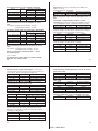
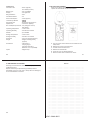
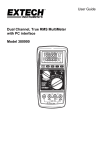
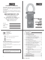
®
®
Certificate of Calibration
We hereby certify that this product has been
calibrated and found to be in accordance
with the applicable SPECIFICATIONS and
STANDARDS.
Accuracies of the standard equipment used in
this calibration are traceable to the National
Standards.
MECO METERS PVT. LTD.
Plot No. EL-60, MIDC Electronic Zone,
TTC Industrial Area, Mahape,
Navi Mumbai - 400710 (INDIA)
Tel : 0091-22-27673311-16, 27673300 (Board)
Fax : 0091-22-27673310, 27673330
E-mail : [email protected]
Web : www.mecoinst.com
SR. NO.
AC CLAMP-ON
POWER
AND
HARMONICS
TESTER
:
CHECKED BY :
DATE
:
MODEL :
PHT4545
MODEL NO.
:
USER MANUAL
EN 61010-2-032
CAT III 600V
Pollution Degree 2
Definition of Symbols :
Caution : Refer to Accompanying Documents
Caution : Risk of Electric Shock
Double Insulation
Over-voltage Category I (CAT I) :
Equipment for connection to circuits in which measurps are taken
to limit the transient over-voltages to an appropriate low level.
Over-voltage Category II (CAT II) :
Energy-consuming equipment to be supplied from the fixed
installation.
Over-voltage Category III (CAT III) :
Equipment in fixed installations.
WARNING :
If the clamp meter is used in a manner Not specified by
the manufacturer, the protection Provided by the clamp
meter may be impaired.
2
TABLE OF CONTENTS
I.
FEATURES ........................................................................ 2
II. PANEL DESCRIPTION ..................................................... 3
III. OPERATING INSTRUCTIONS ......................................... 6
lll.1. Measurenment of ACA ............................................ 6
lll.1.1. True RMS value of AC Current ................................ 7
lll.1.2. HOLD, MAX, MIN and.PEAKofAC Current ............. 7
lll.1.3. Harmonics of AC Current in Magnitude (V) ............ 8
lll.1.4. Harmonics ofAC Current in Percentage (%) ........... 8
lll.1.5. Total Harmonic Distortion (% THD-F) ...................... 9
lll.1.6. Crest Factor(C.F.) .................................................. 10
lll.2. Measurement of AC Voltage ............................................ 11
lll.2.1. True RMS value of AC Voltage ............................. 11
lll.2.3. HOLD, MAX, MIN and PEAK value of AC Voltage 12
lll.2.3. Harmonics of AC Voltage in Magnitude (V) ........... 13
lll.2.4. Harmonics of AC Voltage in Percentage (%) ........ 14
lll.2.5. Total Harmonics Distortion (% THD-F) .................. 14
lll.2.6. Crest Factor (C.F.) ................................................. 15
lll.3. Measurement of Single Phase AC Power Quality ........... 16
lll.3.1. Single Phase AC Watt and Power Factor (PF) ..... 17
lll.3.2. Apparent Power (VA, KVA) and
Reactive Power (VAR, KVAR) ............................... 17
lll.3.3. Phase Angle (u) ..................................................... 18
lll.3.4. Horse Power (H.P) ................................................ 18
lll.3.5. Energy (WH, or KWH) ........................................... 19
lll.4 Measurement ot the Balanced 3 Phase AC Power
Quality .................................................................... 20
lll.5 Measurement of the Balanced 3 Phase Sequence
lll.6 Measurement of Resistance and Continuity with
Beeper ................................................................... 23
IV. SET THE CT RATIO ........................................................ 24
V. DISABLE AUTO-POWER-OFF ....................................... 24
Vl. SPECIFICATIONS (230C±50C) ........................................ 25
Vll. BATTERY REPLACEMENT ........................................... 30
Vlll. MAINTENANCE & CLEANING ....................................... 31
3
4545 : 28-09-2012
1. FEATURES
2. PANEL DESCRIPTION
a. Active (W, KW, HP), reactive (VAR, KVAR) and
apparent (VA, KVA) power.
b. Power factor (PF), phase angle (u), and energy
(WH, KWH).
c. Non-interrupted AC current harmonic analysis.
d. 1 to 99th order of harmonics at 2.0% basic accuracy.
e. Total harmonic distortion (%THD-F) and crest factor
(CF).
f.
True RMS measurement of V and A at 0.5% basic
accuracy.
g. Fast peak function (39ms for 50 Hz, 33ms for 60Hz).
h. Resistance and Continuity with Beeper Measurement
of balanced 3f power.
j.
Measurement of balanced 3f sequence.
k. Programmable CT ratio from 1 to 250.
l.
Max, Min and data hold functions.
m. Active power in H.P.
n. Auto power off function in 30 minutes.
4
1. Transformer Jaw Assembly
This is used to pick up current signal. To measure AC current
or Power/Watt, the jaw must enclose conductor completely.
2. Transformer Trigger
Press the trigger to open the jaw.
3. Rotary Switch
This is used to turn the power on and select measurement
of current, voltage or power.
4. MAX/MIN/HOLD/PEAK
In the measurement of A, or V, press this button to perform
function of MAXIMUM, MINIMUM, HOLD or PEAK.
If this button is hold when turning on power, the tester can
perform measurement of phase sequence instead of phase
angle in the balanced 3f power system.
5. s 3f Button
This button is used to increment order of harmonics or CT
ratio. When the rotary switch is set at W position, press this
button to select measurement of balanced 3f power instead
of single-phase power.
6. FUNC Button
In the measurement of A, or V, press this button to select
function of harmonics, THD-F, or CF. In the measurement of
W with PF, press this button to select function of VA, VAR,
phase angle, HP, or energy (KWH).
7. LCD
This is a 4+4 digit Liquid Crystal Display. Function symbols,
units, sign, decimal points, low battery symbols, max, min
symbols, peak and harmonic symbols are included.
8. Symbols Those are symbols of selected functions such as,
Hamonic, PEAK, MAX, MIN or HOLD.
9. Primary Digits
The primary digits display the main function such as voltage,
current, wattage, and apparent power.
5
10. Secondary Digits
These digits display secondary function of measurement,
such as power factor, reactive power, and the order of
harmonics.
11. Symbols of Units
These are unit symbols for Current, voltage, and power.
The nominal frequency (50 or 60 Hz) of measurement is
displayed above these unit symbols.
12. V Input Terminal
This terminal is used as input for voltage and power
measurements.
13. COM Terminal
This terminal is used as common reference input.
14. Frequency Select Function
Press this button to select nominal frequency (50 or 60Hz)
15. t button
It is used to decrement the order of hamonics or CT ratio.
Holding this button when turning on the power will fix the
measuring frequency at 50 or 60 Hz
Symbol of Current Transformer (CT)
16.
If the CT ratio is not 1, this symbol will be displayed in LCD.
6
7
4545 : 28-09-2012
3. OPERATING INSTRUCTIONS
3. 1.1. True RMS value of AC Current
3.1 Measurement of ACA
NOTE:
1. Set the rotary switch at the A position.
2. The unit will measure and display signal frequency. If users
wish to fixed the frquency 50 or 60, users can hold the t
button when turning on the power.
3. If the peak value of the input AC current is greater than the
maximum value of the range, then symbol of OL will be
displayed.
NOTE : Whenever the rotary switch is set at new position, the CT
ratio will be displayed first. If the CT ratio is not 1, a symbol "
"
will be shown in the LCD display for the measurment of A. The
reading of current shown in LCD is equal to the true RMS value
measured by the tester multiplied by CT ratio (A LCD = ARMS x CT).
WARNING : Make sure that all the test leads are disconnected
from the meter's terminals for current measurement.
a. Set the rotary switch at A Then select the correct frequency
by pressing the 50/60 Hz button.
b. Press the trigger to open the jaw and fully enclose the
conductor to be measured.
c. Read the measured value from the LCD display.
3. 1.2. HOLD, MAX, MIN and PEAK of AC Current.
a. Set the rotary switch at A. Then select the correct frequency
by pressing the 50/60 Hz button.
b. Press the trigger to open the jaw and fully endose the
conductor to be measured.
c. The measured value from the LCD display. If the HQLD
button is pressed, the symbol of “HOLD”, “MAX”, “MIN” or
“PEAK” will be shown in LCD alternatively. And the value
of the HOLD, MAX, MIN or PEAK function will be displayed
in LCD alternatively.
d. To return to the display of current measurement, hold the
HOLD button for more than 2 seconds.
NOTE : The PEAK function displays the maximum value of the
input waveform. The sampling time for the PEAK function is
39ms (50Hz) or 33ms (60Hz). The HOLD, MAX, or MIN function
displays the true RMS value.
8
9
3. 1.3. Harmonics of AC Current in Magnitude
a. Set the rotary switch at A. Then select the conect frequency
by pressing the 50/60 Hz button.
b. Press the trigger to open the jaw and fully enclose the
conductor to be measured.
c. Press the FUNC button once. The symbols of “Harmonic”
and “NO.” will be shown in LCD. The n-th order (1 to 99)
will be shown in the upper row digits.
d. Press the s or t button to increment or decrement the
order of harmonics in the upper row digits. The number
will roll over when the maximum (99) or minimum (1) is
reached.
3. 1.4. Harmonics of AC Current in Percentage (%)
d. Press the s or t button to increment or decrement the
order of harmonics in the upper row digits. The number
will roll over when the maximum (99) or minimum (1) is
reached.
3. 1.5. Total Harmonic Distortion (% THD-F)
a. Set the rotary switch at A. Then select the correct frequency
by pressing the 50/60 Hz button.
b. Press the trigger to open the jaw and fully enclose the
conductor to be measured.
c. Press the FUNC button three times. The symbols of “THD”
and “%” will be shown in LCD. The total harmonic distortion
in percentage with respect to the fundamental frequency
(50 or 60 Hz) will be measured and displayed.
%THD-F = ( (V22+ V32 + ... V492+ V502) / V1) * 100
Where,
V1: magnitude at the 50 or 60 Hz
V2: magnitude at the second harmonics
...
V50: magnitude at the 99-th harmonics.
a. Set the rotary switch at “A” position. Then select the correct
frequency by pressing the 50/60 Hz button,
b. Press the trigger to open the jaw and fully enclose the
conductor to be measured.
c. Press the FUNC button twice. The symbols of “Harmonic”
and “NO.” will be shown in LCD. The n-th order (1 to 99)
will be shown in the upper row digits.
10
11
4545 : 28-09-2012
3. 1.6. Crest Factor (C.F.)
a. Set the rotary switch at A. Then select the correct frequency
by pressing the 50/60 Hz button.
b. Press the trigger to open the jaw and fully enclose the
conductor to be measured.
c. Press the FUNC button four times. The symbols of C.F.
will be shown in LCD. The crest factor (C.F.) will be
measured and displayed. The crest factor (CF) is defined
as following:
C.F. = (peak value) / (RMS value)
3.2 Measurement of AC Voltage
NOTE :
1. The unit will measure and display signal frequency. If users
wish to fixed the frquency at 50 or 60, users can hold the t
button when turning on the power.
2. If the peak value of the input AC voltage is greater than the
maximum value of the range, then symbol of OL will be
displayed.
NOTE : Whenever the rotary switch is set at a new position, the
CT ratio will be displayed first. If the CT ratio is not 1, a symbol
of “
” will be shown in the LCD display.
WARNING :
Maximum input for ACV is 600. Do not attempt to take any voltage
measurement that exceeds the limits. Exceeding the limits could
cause electrical shock and damage to the clamp meter.
12
3. 2.1. True RMS value of AC Voltage
a. Set the rotary switch at position V. Then select the correct
fundamental frequency by pressing the 50/60 Hz button.
b. Insert the test leads into the input jack. Connect the test
prods of the test leads in PARALLEL to the circuit to be
measured.
c. Read the measured RMS value from the LCD display.
3. 2.2. HOLD, MAX, MIN and PEAK value of AC Voltage
a. Set the rotary switch at position V. Then select the correct
fundamental frequency by pressing the 50/60 Hz button.
b. Insert the test leads into the input jack. Connect the test
prods of the test leads in PARALLEL to the circuit to be
measured.
c. The measured value is displayed in the LCD display. If the
HOLD button is pressed, the symbol of “HOLD”, “MAX”,
“MIN” or “PEAK” will be shown in LCD alternatively. And
the value of the HOLD, MAX, MIN or PEAK function will be
displayed in LCD alternatively.
d. To return to the display of current measurement, hold the
HOLD button for more than 2 seconds.
14
13
NOTE : The PEAK function displays the maximum value of the
input wavefom.The sampling time for the PEAK function is 39ms
(50Hz) or 33ms (60Hz). The HOLD, MAX, or MIN function displays
the true RMS value.
3. 2.3. Harmonics of AC Voltage in Magnitude (V)
a. Set the rotary switch at position V. Then select the correct
fundamental frequency by pressing the 50/60 Hz button.
b. Insert the test leads into the input jack. Connect the test
prods of the test leads in PARALLEL to the circuit to be
measured.
c. Press the FUNC button once. The symbols of “Harmonic”
and “NO” will be shown in LCD. The n-th order (1 to 99)
will be shown in the upper row digits.
d. Press the s or t button to increment or decrement the
order of harmonics in the upper row digits. The number
will roll over when the maximum (99) or minimum (1) is
reached.
15
4545 : 28-09-2012
3. 2.4. Harmonics of AC Vollage in Percentage (%)
a. Set the rotary switch at position V. Then select the correct
fundamental frequency by pressing the 50/60 Hz button.
b. Insert the test leads into the input jack. Connect the test
prods of the test leads in PARALLEL to the circuit to be
measured.
c. Press the FUNC button twice. The symbols of "Hamonic"
and "NO" will be shown in LCD. The n-th order (1 to 99)
will be shown in the upper row digits.
d. Press the s or t button to increment or decrement the
order of harmonics in the upper row digits. The number
will roll over when the maximum (99) or minimun (1) is
reached.
3. 2.5. Total Harmonic Distortion (% THD-F)
c. Press the FUNC button three times. The symbols of “THD”
and “%” will be shown in LCD. The total harmonic distortion
in percentage with respect to the fundamental frequency
(50 or 60 Hz) will be measured and displayed.
%THD-F=( (V22+V32 + ... +V492+V502)/V1) * 100
Where,
V1: magnitude at the 50 or 60 Hz
V2: magnitude at the second harmonics
...
V50: magnitude at the 50-th harmonics.
3. 2.6. Crest Factor (C.F.)
a. Set the rotary switch at posilion V. Then select the correct
fundamental frequency by pressing the 50/60 Hz button.
b. Insert the test leads into the input jack. Connect the test
prods of the test leads in PARALLEL to the circuit to be
measured.
c. Press the FUNC button four times. The symbols of C.F.
will be shown in LCD. The crest factor (C.F.) will be
measured and displayed. The crest factor (CF) is defined
as following:
C.F. (Crest Factor) = (Peak Value) / (RMS Value)
a. Set the rotary switch at position V. Then select the correct
fundamental frequency by pressing the 50/60 Hz button.
b. Insert the test leads into the input jack. Connect the test
prod’s of the test leads in PARALLEL to the circuit to be
measured.
16
3. 3 Measurement of Single Phase AC Power Quality
NOTE :
1. Set the rotary switch at the W position.
2. Select the correct fundamental frequency of current and
voltage by pressing the 50/60 Hz button
3. If the peak value of the input AC current or AC voltage is
greater than the maximum value of the range, then symbol
of OL will be displayed.
NOTE :
Whenever the rotary switch is set at a new position, the CT ratio
will be displayed first. If the CT ratio is not 1, a symbol of “
”
will be shown in the LCD display for the measurement of W. The
reading of current shown in LCD is equal to the W, VA, and VAR
values measured by the tester multiplied by CT ratio (WLCD= W x
CT, VALCD= VA x CT, VARLCD= VAR x CT, WHLCD = WH x CT).
18
17
3. 3.1 Single Phase AC Watt and Power Factor (PF)
a. Connect the test leads to the voltage source in parallel
with the load.
b. Clamp on one of the wire to the load. The current should
flow frcm the front of the tester to the side of the battery
cover.
c. Set the rotary switch at the W position.
d. Read the values of W or KW and PF shown on LCD. The
unit of watt is automatically scaled.
3. 3.2. Apparent Power (VA, KVA) and Reactive Power (VAR,
KVAR)
a. Connect the test leads to the voltage source in parallel
wilh the load.
b. Clamp on one of the wire to the load. The current should
flow from the front of the tester to the side of the battery
cover.
c. Set the rotary switch at the W position.
d. The value of W, or KW and PF will be displayed in LCD.
e. Press the FUNC button once to display VA or KVA and
VAR or KVAR. The unit is automatically scaled.
19
4545 : 28-09-2012
3. 3.3. Phase Angle (u)
a. Connect the test leads to the voltage source in parallel
with the load.
b. Clamp on one of the wire to the laad. The current should
flow from the front of the tester to the side of the battery
cover.
c. Set the rotary switch at the W position.
e. The value of W, or KW will be displayed in LCD. The unit
of watt is automatically scaled.
f. Press the FUNC button three times to display phase angle
(u) from 1800 to +1800.
NOTE : To display phase angle (u) from 0 to 360, hold the s
button, then turn the power on. Once the tester is turned on in this
way, the tester will display phase angle from 0 to 3600 (when phase
angle function is selected).
3. 3.4. Horse Power (H.P.)
b. Clamp on one of the wire to the load. The current should
flow from the front of the tester to the side of the battery
cover.
c. Set the rotary switch at the W position.
d. The vaiue of W, or KW and PF will be displayed in LCD.
The unit of watt is automatically scaled.
e. Press the FUNC button four times to display power in the
unit of HP.
3. 3.5. Energy (WH, or KWH)
a. Connect the test leads to the voltage source in parallel
with the load.
b. Clamp on one of the wire to the load. The current should
flow from the front of the tester to the side of the battery
cover.
c. Set the rotary switch at the W position.
d. The values of W, or KW and PF will be displayed in LCD.
The unit of watt is automatically scaled.
e. Press the FUNC button five times. A character of H is
displayed in front of reading to indicate energy (WH or
KWH).
a. Connect the test leads to the voltage source in parallel
with the load.
20
21
3.4 Measurement of the Balanced 3 Phase AC Power Quality
a. Connect the black test lead to the voltage L3, and connect
the red test lead to L1.
b. Clamp on one of the wire to L2. The cun ent should flow
from the front of the tester to the side of the battery cover.
c. Set the rotary switch at the W position.
d. Press the s 3f button to select balanced 3f. Symbols
of ‘‘3f3W, 3f4W and BAL” will be shown in LCD.
e. The value of W or KW and PF will be displayed in LCD.
The unit of watt is automatically scaled.
f. If the FUNC button is pressed again, the apparent power
(VA) and reactive power (VAR) will be shown in LCD.
g. To measure the phase angle and phase sequence, users
can press the FUNC button again.
h. If the FUNC button is pressed again, the true power in the
unit of Horse Power (HP) will be shown in LCD.
i. To measure the energy (WH), users can press the FUNC
button again. The current energy (WH or KWH) will be
shown in LCD.
NOTE : Users can also obtain the measurements of VA, VAR,
Phase Angle, phase sequence, HP, and energy (WH) for balanced
3f power system. The operations are the same as the
measurements for the single-phase power system.
22
NOTE : The reading of current shown in LCD is equal to the
W, VA, and VAR value measured by the tester multiplied by CT
ratio (WLCD= W x CT, VALCD= VA x CT, VARLCD= VAR x CT,
WHLCD= WH x CT)
23
4545 : 28-09-2012
3.5 Measurement of the Balanced 3 Phase Sequence
a. Set the rotary switch at the W position
b. Connect the black test lead to the voltage L3, and connect
the red test lead to L1.
c. Clamp on to the wire of L2. The current should flow from
the front of the tester to the side of the battery cover.
d. Press the s 3f button to select 3 phase power system. A
symbol of 3f will be shown in LCD.
e. Press the FUNC button to select phase angle function.
The LCD will show L123 to indicate the clockwise sequence
in the upper row digits of LCD. Or the LCD will show L132
to indicate counter clockwise sequence.
3.6 Measurement of Resistance and Continuity with Beeper
24
25
a. Set the rotary switch at V
b. Insert the test leads into the input jack.
c. Connect the test prods of the test leads to the two ends of
the resistor or circuit to be measured.
d. Read the measured value from the LCD display.
e. If the resistance is lower than 50 V, a beeping sound shall
be heard.
4. SET THE CT RATlO
To set the CT ratio, hold the FUNC button, and then turn the
power on. A symbol of ‘‘
’’ will be shown in LCD. The default
value of CT is 1. To change the CT ratio, users can press the
s or t button to increment or decrement the value by
1, Holding the s or t button will speed up the process of
incrementing or decrementing.
To exit the setting of CT ratio, press the FUNC button.
6. SPECIFICATIONS(230C±50C)
AC Watt (50 or 60 Hz, PF 0.5 to 1. CT = 1, Voltage > AC 5V,
Current > AC 5A, and continuous waveform)
Range
Resolution
Accuracy of Readings1
>20V & >20A <20V or <20A
10.0 - 999.9 W
0.1W
±2% ± 20dgts ±2% ± 40dgts
1.000 - 9.999 KW 0.001 KW ±2% ± 20dgts ±2% ± 40dgts
10.00 99.99 KW
0.01 KW ±2% ± 20dgts ±2% ± 40dgts
100.0 - 999.9 KW
0.1 KW ±2% ± 20dgts ±2% ± 40dgts
1000 - 9999 KW
1 KW ±2% ± 20dgts ±2% ± 40dgts
1
For CTf1, the accuracy in percentage is the same (±2%).
But the additional wattage should be multiplied by the CT
ratio.
For example, ±2.0W becomes ±2.0W * CT ratio
±4.0W becomes ±4.0W * CT ratio
5. DISABLE AUTO-POWER-OFF
The tester has an auto-power-off function. The tester will turn
the power off after power is turned on for 30 minutes. To disable
the auto power off function, hold the FUNC button for more
than 2 seconds. A beep sound will be heard to indicate that
the auto power off function is disabled.
26
27
4545 : 28-09-2012
AC Apparent Power (VA, from 0.000VA to 9999 KVA)
Range
Resolution
Accuracy of Readings2
>20V & >20A <20V or <20A
10.0 - 999.9 VA
0.1VA ±2% ± 20dgts ±2% ± 40dgts
1.000 - 9.999 KVA 0.001 KVA ±2% ± 20dgts ±2% ± 40dgts
10.00 - 99.99 KVA 0.01 KVA ±2% ± 20dgts ±2% ± 40dgts
100.0 - 999.9 KVA 0.1 KVA ±2% ± 20dgts ±2% ± 40dgts
1000 - 9999 KVA
1 KVA ±2% ± 20dgts ±2% ± 40dgts
2
For CTf1, the accuracy in percentage is the same (±2%).
But the additional VA should be multiplied by the CT
ratio.
For example, ±2.0VA becomes ±2.0VA * CT ratio
±4.0VA becomes ±4.0VA * CT ratio
AC Reactive Power (VAR, from 0.000 VAR to 9999 KVAR)
Resolution
Accuracy of Readings3
Range
>20V & >20A <20V or <20A
10.0 - 999.9 VAR 0.1VAR ±2% ± 30dgts ±3% ± 40dgts
1.000 - 9.999 KVAR 0.001 KVAR ±2% ± 30dgts ±3% ± 40dgts
10.00 - 99.99 KVAR 0.01 KVAR ±2% ± 30dgts ±3% ± 40dgts
100.0 - 999.9 KVAR 0.1 KVAR ±2% ± 30dgts ±3% ± 40dgts
1000 - 9999 KVAR 1 KVAR ±2% ± 30dgts ±3% ± 40dgts
3
For CTf1, the accuracy in percentage is the same (±2%).
But the additional VAR should be multiplied by the CT
ratio.
For example, ±3.0VAR becomes ±3.0VAR * CT ratio
±4.0VAR becomes ±4.0VAR * CT ratio
Range of CT (Current Transformer) Ratio : 1 to 250
H.P. (Horse Power)
1 H.P. = 746 W
AC Active Energy ( WH, or KWH, from 0 WH to 999,999
KWH) WH = W * Time (in hours)
AC Current (50 or 60 Hz, Auto Range, True RMS, Crest
Factor < 4, CT=1)
(Overload Protection AC 2000A)
Range
Resolution
Accuracy of Readings4
10.0 - 1500.0 A
0.01 A
± 2% ± 5dgts
4
For CT = 1, the accuracy in percentage is the same (±2%).
But the additional digits should be multiplied by the CT
ratio.
For example, ±5 digits becomes ±5 digits * CT ratio
AC Voltage (50 or 60 Hz, Auto Range, True RMS, Crest Factor
< 4, Input Impedance 10 MV, Overload Protection AC 800V)
Range
Resolution
Accuracy of Readings
10.0 V - 600.0 V
0.1 V
± 0.5% ± 5dgts
Harmonics of AC Voltage in Percentage (1 to 99 order,
minimum voltage at the 50 or 60 Hz > AC 80V. If the voltage is
0 at 50 or 60 Hz, all the percentage (%) display is 0.)
Range
Resolution
Accuracy
1 - 20th
0.1%
±2%
21 - 49th
0.1%
4%of reading ± 2.0%
50 - 99th
0.1%
6%of reading ± 2.0%
Harmonics of AC Voltage in Magnitude (1 to 99th order,
minimum voltage at the 50 or 60 Hz > AC 80V)
Range
Resolution
Accuracy
1 - 20th
0.1%
± 2.0% ± 0.5V
21 - 49th
0.1%
4%of reading ± 0.5V
50 - 99th
0.1%
6%of reading ± 0.5V
Harmonics of AC Current in Percentage (1 to 99th order,
minimum current at the 50 or 60 Hz o 20 A. If the current is 0
at 50 or 60 Hz, all the percentage (%) display is 0.)
Range
Resolution
Accuracy
0.1%
±2%
1 - 20th
21 - 49th
0.1%
4% of reading ± 2.0%
50 - 99th
0.1%
6% of reading ± 2.0%
Harmonics of AC Current in Magnitude (1 to 99th order,
minimum current at the 50 or 60 Hz > 20A)
Range
Resolution
Accuracy
1 - 20th
0.1%
± 2% of reading ± 0.4A
21 - 49th
0.1%
± 4% of reading ± 0.4A
0.1%
± 6% of reading ± 0.4A
50 - 99th
Power Factor (PF)
Range
Resolution
Accuracy
>20V & >20A <20V or <20A
0.000 - 1.000
0.001
± 0.04
± 0.1
Phase Angle (u)
Range
Resolution
Accuracy
-180 to 1800
0.10
±10
0 to 3600
0.10
±10
Total Harmonic Distortion (THD-F with respect to the 50 or 60
Hz, min. value at the 50 or 60 Hz > 80V and > 20 A, 1 to 50
Harmonics. If the voltage or current is 0 at 50 or 60 Hz, all the
percentage (%) dispiay is 0)
Range
Resolution
Accuracy
0.0 - 20%
0.1%
±2.0%
20 - 100%
0.1%
± 6% of reading ±1%
100 - 999.9%
0.1%
±10% of reading ±1%
Peak Value of AC Voltage (peak value > 5V) or AC Current
(peak value > 20A)
Range
Sampling Time
Accuracy of Reading
50 Hz
39 ms
± 5% ± 30 digits
60 Hz
33 ms
± 5% ± 30 digits
Crest Factor (C.F.) of ACV (peak value > 5V) or ACA (peak
value > 20A)
Range
Resolution
Accuracy of Reading
1.00 - 99.99
0.01
± 5% ± 30 digits
Resistance (V) and Continuity (Beep if less than 50V)
Range
Resolution
Accuracy
7.0 - 999.9 V
0.1 V
±5V
1000 - 1200 V
1V
±5V
If reading is less than 7V, it is displayed as 0V
Frequency (RMS Value >10V) or ACA (RMS value >30A)
Range
Resolution
Accuracy of Readings
45 - 65
0.1
± 0.2 Hz
28
29
30
31
4545 : 28-09-2012
Indoors Use
Conductor Size
: 55mm (approx.),
64 x 24mm (bus bar)
Battery Type
: two 1.5V SUM-3
Display
: 4+4 digits LCD
Range Selection
: Auto
Overload lndication
: OL
Power Consumption
: 10mA (approx.)
Low battery Indication
:
Auto-Power-Off
: 30 minutes after power-on
Update Time
: 2 times/sec. (display)
7. BATTERY REPLACEMENT
When the low battery symbol is displayed on the LCD,
replace the old batteries with two new batteries.
No. Of Samples per Period : 512 (voltage or current)
256 (power)
Operating Temperature
: -100C to 500C
Operating Humidity
: less than 85% relative
Altitude
: up to 2000M
Storage Temperature
: -200C to 600C
Storage Humidity
: less than 75% relative
Dimension
: 210 x 62 x 35.6mm (approx.)
Weight
: 640gms including battery
(approx.)
Accessories
: Test leads x 1
Carrying bag x 1
Instruction manual x 1
Batteries 1.5V x 2 (installed)
Option
: Alligator clips
A. Turn the power off and remove the test leads from the
clamp meter.
B. Remove the screw of the back cover.
C. Lift and remove the back cover.
D. Remove the old batteries.
E. Insert two new 1.5V SUM-3 batteries.
F. Place the back cover and secure the screw.
32
8. MAINTENANCE & CLEANING
Servicing not covered in this manual should only be performed by
qualified personnel.
Repairs should only be performed by qualified personnel.
Periodically wipe the case with a damp doth and detergent;
do not use abrasives or solvents.
34
33
NOTE
○
○
○
○
○
○
○
○
○
○
○
○
○
○
○
○
○
○
○
○
○
○
○
○
○
○
○
○
○
○
○
○
○
○
○
○
○
○
○
○
○
○
○
○
○
○
○
○
○
○
○
○
○
○
○
○
○
○
○
○
○
○
○
○
○
○
○
○
○
○
○
○
○
○
○
○
○
○
○
○
○
○
○
○
○
○
○
○
○
○
○
○
○
○
○
○
○
○
○
○
○
○
○
○
○
○
○
○
○
○
○
○
○
○
○
○
○
○
○
○
○
○
○
○
○
○
○
○
○
○
○
○
○
○
○
○
○
○
○
○
○
○
○
○
○
○
○
○
○
○
○
○
○
○
○
○
○
○
○
○
○
○
○
○
○
○
○
○
○
○
○
○
○
○
○
○
○
○
○
○
○
○
○
○
○
○
○
○
○
○
○
○
○
○
○
○
○
○
○
○
○
○
○
○
○
○
○
○
○
○
○
○
○
○
○
○
○
○
○
○
○
○
○
○
○
○
○
○
○
○
○
○
○
○
○
○
○
○
○
○
○
○
○
○
○
○
○
○
○
○
○
○
○
○
○
○
○
○
○
○
○
○
○
○
○
○
○
○
○
○
○
○
○
○
○
○
○
○
○
○
○
○
○
○
○
○
○
○
○
○
○
○
○
○
○
○
○
○
○
○
○
○
○
○
○
○
○
○
○
○
○
○
○
○
○
○
○
○
○
○
○
○
○
○
○
○
○
○
○
○
○
○
○
○
○
○
○
○
○
○
○
○
○
○
○
○
○
○
○
○
○
○
○
○
○
○
○
○
○
○
○
○
○
○
○
○
○
○
○
○
○
○
○
○
○
○
○
○
○
○
○
○
○
○
○
○
○
○
○
○
○
○
○
○
○
○
○
○
○
○
○
○
○
○
○
○
○
○
○
○
○
○
○
○
○
○
○
○
○
○
○
○
○
○
○
○
○
○
○
○
○
○
○
○
○
○
○
○
○
○
○
○
○
○
○
○
○
○
○
○
○
○
○
○
○
○
○
○
○
○
○
○
○
○
○
○
○
○
○
○
○
○
○
○
○
○
○
○
○
○
○
○
○
○
○
○
○
○
○
○
○
○
○
4545 : 28-09-2012