1
Flashlink User Manual
FR-DWDM
Flashlink Dense Wavelength
Division Multiplexing System
network-electronics.com
Rev. 7
FR-DWDM
Rev. 7
Index
Revision history............................................................................................................................................5
1 General information .................................................................................................................................6
1.1 Handling of optical fibers....................................................................................................................6
1.2 Laser safety precautions ......................................................................................................................6
1.3 Connector cleaning..............................................................................................................................8
1.4 Power dissipation in the DWDM-system.............................................................................................9
1.5 Warranty Statement ...........................................................................................................................10
2 Interconnection of the DWDM-systems ...............................................................................................11
2.1 4-channel systems ..............................................................................................................................12
2.2 8-channel systems ..............................................................................................................................13
2.3 12-channel systems ............................................................................................................................15
2.4 16-channel systems ............................................................................................................................18
2.5 32-channel systems ............................................................................................................................21
2.6 40-channel systems ............................................................................................................................21
3 DWDM system description ....................................................................................................................22
3.1 Specifications for 16-ch system .........................................................................................................23
3.2
Optical specifications for 32-channel system..............................................................................26
3.3
Optical specifications for 40-channel system..............................................................................26
3.4 Wavelength Availability Chart according to ITU-T G.694.1 for 32- and 40-ch systems..................27
3.5 Connection drawing...........................................................................................................................28
3.6 Module card LEDs.............................................................................................................................28
4 Power connection and RS-422 connection............................................................................................29
4.1 Pin-out DB9:......................................................................................................................................29
4.2. RS-422 connection ............................................................................................................................30
4.3 Pin-out RS-422...................................................................................................................................30
4.4 RS-422 protocol .................................................................................................................................31
4.5 Connecting several sub-racks together .............................................................................................31
4.6 Address setting on each sub-rack ......................................................................................................32
5 Module card mounting ...........................................................................................................................34
5.1 Removing the front panel...................................................................................................................34
5.2 Card insertion....................................................................................................................................36
Network Electronics ASA, Thorøya, 3204 Sandefjord, Norway, Tel.:+47 33 48 99 99 Fax: +47 33 48 99 98
E-mail: [email protected] - Web: http://www.network-electronics.com
Technical specifications are subject to be changed without notice
2
FR-DWDM
Rev. 7
5.3 Card removal .....................................................................................................................................38
5.4 Attaching the front panel ...................................................................................................................39
6 Fiber optics ..............................................................................................................................................41
6.1 Handling of optical fibers..................................................................................................................41
6.2 Fiber optic Connector........................................................................................................................42
6.3. DWDM background..........................................................................................................................43
6.4 Transmission budget..........................................................................................................................45
6.5 flashlink® 16-channel 200GHz DWDM Wavelength Availability acc. to ITU-T G.694.1.................46
7 3R regeneration.......................................................................................................................................47
7.1 Introduction .......................................................................................................................................47
7.2 3R Specifications ...............................................................................................................................49
7.3 Frame configuration..........................................................................................................................49
8 Application notes ....................................................................................................................................51
8.1 3R-regeneration used in a long-haul connection ..............................................................................51
8.2 ADM-nodes ........................................................................................................................................51
Troubleshooting .........................................................................................................................................53
Declaration of conformity with CE ..........................................................................................................55
General environmental requirements for flashlink® equipment .........................................................55
Product Warranty .....................................................................................................................................56
Materials declaration and recycling information ...................................................................................57
Materials declaration ................................................................................................................................57
Environmentally-friendly use period.......................................................................................................57
Recycling information ...............................................................................................................................58
Network Electronics ASA, Thorøya, 3204 Sandefjord, Norway, Tel.:+47 33 48 99 99 Fax: +47 33 48 99 98
E-mail: [email protected] - Web: http://www.network-electronics.com
Technical specifications are subject to be changed without notice
3
FR-DWDM
Rev. 7
Accessories enclosed
•
•
•
•
Plastic dust caps for fiber optical connectors
Fiber optic patch cords for interconnection of sub-rack frames
110Ω termination plugs for the Gyda® system controller (optional)
Cat-5 cables for RS-422 connection to Gyda® (optional)
Network Electronics ASA, Thorøya, 3204 Sandefjord, Norway, Tel.:+47 33 48 99 99 Fax: +47 33 48 99 98
E-mail: [email protected] - Web: http://www.network-electronics.com
Technical specifications are subject to be changed without notice
4
FR-DWDM
Rev. 7
Revision history
The latest version is always available in pdf-format on our web-site:
http://www.network-electronics.com/
Current revision of this document is the uppermost in the table below.
Revision Replaces
Date
(yy.mm.dd)
Change Description
7
6
2007-10-26 AS New front page and removed old logo.
6
5
2007-10-17 AS Added Materials Declaration and EFUP
5
4
04.09.13 RS
Added information on 3R re-generation
4
3
04.03.05 RS
Added information on the 32-ch and the 40-ch systems
3
2
03.05.14 RS
Corrected RS-422 interconnection of sub-racks
2
1
02.01.08 RS
622Mbps Telecom version no longer available
1
0
01.07.19 RS
Added specification on optical filters and optical input
0
D
01.05.14 RS
Product release
D
C
01.04.04 RS
Added possibility for 2+2 channel system, separated
SDI and Telecom into separate part numbers, added note
on power dissipation
C
B
01.03.27 RS
Changed specification
B
A
01.02.15 RS
Corrected specification
01.02.04 RS
Preliminary revision
A
Network Electronics ASA, Thorøya, 3204 Sandefjord, Norway, Tel.:+47 33 48 99 99 Fax: +47 33 48 99 98
E-mail: [email protected] - Web: http://www.network-electronics.com
Technical specifications are subject to be changed without notice
5
FR-DWDM
Rev. 7
1 General information
1.1 Handling of optical fibers
This product includes fiber optic equipment. Access to the optical signal path is given through the optical
connectors (see separate chapter).
Even though a fiber optic cable can look almost the same as an electrical wire, special care must be taken.
Inside the cable is a fiber made of glass. Glass has very different physical properties than the copper used
in electrical wires.
In practical terms this means that these precautions must be taken:
•
•
•
Do not bend the fiber too much
Do not put anything on top of the optical fiber.
Keep the connectors clean from dust
If a fiber is bent to much, parts of the transmitted light is lost or in worst case the glass is broken. All the
datasheets of optical fibers have a point called "minimum bend radius". This means that any bending of
the fiber corresponding to a bend radius less than the given value will make the light leak out of the fiber.
A typical value is 20 mm to 40 mm (Telcordia standard) for single mode fibers.
You should also avoid putting any heavy items on top of the optical fibers, because this will change the
optical properties of the fiber, and contribute to errors in the transmitted signal.
Unless the fiber is damaged, it will regain its optical properties after a bend is straightened out or the
items are removed / the squeeze is released.
1.2 Laser safety precautions
Guidelines to limit hazards from laser exposure.
All the available EO units in the flashlink® range include a laser.
Therefore this note on laser safety should be read thoroughly.
The lasers emit light at wavelengths around 1550 nm. This means that the human eye cannot see the
beam, and the blink reflex cannot protect the eye. (The human eye can see light between 400 nm to 700
nm).
Network Electronics ASA, Thorøya, 3204 Sandefjord, Norway, Tel.:+47 33 48 99 99 Fax: +47 33 48 99 98
E-mail: [email protected] - Web: http://www.network-electronics.com
Technical specifications are subject to be changed without notice
6
FR-DWDM
Rev. 7
A laser beam can be harmful to the human eye (depending on laser power and exposure time), therefore:
!!
BE CAREFUL WHEN CONNECTING / DISCONNECTING FIBER PIGTAILS (ENDS).
NEVER LOOK DIRECTLY INTO THE END OF THE FIBER.
NEVER USE MICROSCOPES, MAGNIFYING GLASSES OR EYE LOUPES TO LOOK INTO A
FIBER END.
USE LASER SAFETY EYEWEAR BLOCKING LIGHT AT 1310 nm AND AT 1550 nm.
Instruments exist to verify light output power: Power meters, IR-cards etc.
The FR-2RU-10-2 is classified as Class 1 laser product according to EN 60 825-1:94/A11:96, and
CFR Ch1(1997) Part 1040.10.
If the front panel is removed, the FR-2RU-10-2 is classified as Class 1 laser product according to
EN 60 825-1:94/A11:96, and class IIIb according to CFR Ch1(1997) Part 1040.10.
Maximum output power: 17 mW.
Operating wavelengths: 1550 ± 20nm.
< 5mW
>1270nm
Network Electronics ASA, Thorøya, 3204 Sandefjord, Norway, Tel.:+47 33 48 99 99 Fax: +47 33 48 99 98
E-mail: [email protected] - Web: http://www.network-electronics.com
Technical specifications are subject to be changed without notice
7
FR-DWDM
Rev. 7
1.3 Connector cleaning
Optical connectors should be kept clean at all times. Whenever a connector is disconnected the enclosed
protective dust cap should be put on. This protects the ferrule used for fiber alignment and prevents the
surface from being scratched or damaged.
Figure 1.1: The different parts of an SC/PC connector
Cleaning procedure:
If the ferrule is dirty it must be cleaned before re-connection.
If a clean connector is pressed against a dirty connector, both connectors will become dirty resulting in
possible degradation of signal quality. Or even worse, you may damage the surface of the connector(s).
We recommend that the cleaning procedure is done by using a special cleaning-tape suitable for this
purpose, called CleTop (see picture below).
Network Electronics ASA, Thorøya, 3204 Sandefjord, Norway, Tel.:+47 33 48 99 99 Fax: +47 33 48 99 98
E-mail: [email protected] - Web: http://www.network-electronics.com
Technical specifications are subject to be changed without notice
8
FR-DWDM
Rev. 7
1.4 Power dissipation in the DWDM-system.
Due to the need of very stable laser emission wavelengths, a precise temperature control of the laser
cavity is needed. The laser wavelength will drift with changing temperature if the laser is not controlled.
This means that the internal temperature of the laser must be kept at a constant level for all operation
temperatures.
This is done through the use of a Peltier element placed within the laser package. The function of the
Peltier element is to control the temperature in a similar way as a refrigerator. If the ambient temperature
increases the Peltier element will cool the inside of the laser package to keep the temperature at a constant
level. If the opposite is the case and the ambient temperature decreases, the Peltier element will heat the
inside of the package to keep the internal temperature constant. The quantity of heat absorbed or
produced is proportional to the current flowing through the contact. In practical terms this means that the
current is proportional to the temperature difference between the ambient temperature and the desired
temperature within the laser package.
If the ambient temperature is lower than the package temperature, the power dissipated will support the
heating process of the device by increasing the ambient temperature. On the other hand, if the ambient
temperature is much higher than the desired package temperature (about +22°C) it may cause the laser to
malfunction. The current, which is proportional to the temperature difference, implies power dissipation
and an increase of the ambient temperature.
This increased ambient temperature will again increase the current through the Peltier element in order to
lower the internal package temperature. The increased current will make more power dissipate thereby
increasing the ambient temperature, and so on.
To avoid this, proper ventilation of the DWDM-system is needed. In the case of a 16-channel installation
a fan must be installed above the uppermost sub-rack frame. Below the lowest sub-rack frame it is
recommended to have 1RU of free space to ensure good airflow through the sub-rack frames.
A32-channel system needs 18RU of rack space. Additional rack space needed for ventilation is 1RU at
the bottom for cold air intake, 1RU for a fan after 4 frames with an additional 1RU above for cold air
intake for the 4 uppermost frames.
1RU Fan, hot air exhaust
8RU 4x flashlink DWDM frames
1RU Cold air intake
2RU flashlink DWDM filter frame
1RU Fan, hot air exhaust
8RU 4x flashlink DWDM frames
1RU Cold air intake
1RU Fan, hot air exhaust
10RU 5x flashlink DWDM frames
1RU Cold air intake
Network Electronics ASA, Thorøya, 3204 Sandefjord, Norway, Tel.:+47 33 48 99 99 Fax: +47 33 48 99 98
E-mail: [email protected] - Web: http://www.network-electronics.com
Technical specifications are subject to be changed without notice
9
FR-DWDM
2RU
1RU
10RU
1RU
Rev. 7
flashlink DWDM filter frame
Fan, hot air exhaust
5x flashlink DWDM frames
Cold air intake
The operational temperature for the DWDM-system is 0°-40°C.
1.5 Warranty Statement
The following warranty terms and conditions shall apply to all products manufactured by Network
Electronics.
Guarantee
Network Electronics guarantees the good quality of the goods supplied for the period started, or when no
period is started for a period of three (3) years as from the date from which they have been put in use, but
in no event for more than forty (40) months as from the date of despatch, against all defects or failures
which appear therein under proper use, and arise solely from faulty materials or workmanship, is being
understood that:
Such guarantee does not cover damage sustained by normal wear or tear or any damage arising in
consequence of negligence or improper use and storage.
Such guarantee shall not include any items to which a specific manufacturer’s guarantee applies.
Network Electronics liability under this guarantee shall be to supply to the purchaser free of charge,
replacements of parts that have proved to be defect. These will be repaired to our costs, provided that we
are informed by purchaser in writing, telefax or mail within fourteen days after the defects has been
revealed, and the defective goods have been placed at Network Electronics disposal. The defective parts
shall become Network Electronics property as soon as they have been replaced.
Product Liability
Network Electronics shall not be liable to damages to persons or property unless the purchaser proves that
the loss is due to negligence on the part of Network Electronics or Network Electronics personnel.
Network Electronics shall not be liable for indirect losses of any kind such as loss of trade, loss of profit
etc.
In the event that Network Electronics is held liable by a third party for damages arising from product
liability the purchaser shall be obliged to become a part to any litigation initiated by a third part against
Network Electronics.
Network Electronics ASA, Thorøya, 3204 Sandefjord, Norway, Tel.:+47 33 48 99 99 Fax: +47 33 48 99 98
E-mail: [email protected] - Web: http://www.network-electronics.com
Technical specifications are subject to be changed without notice
10
FR-DWDM
Rev. 7
2 Interconnection of the DWDM-systems
The interconnection of each sub-rack is shown below, and this will apply to all sub-racks and systems.
The optical filter is marked with the respective DWDM wavelengths. The optical port must be connected
to the corresponding wavelength on the channel cards, otherwise the optical filter will suppress the
information running on that channel.
The ports are as follows:
C=
Common port
1-4 = Channel wavelengths for sub-rack channels 1-4
U=
Upgrade port
The GYDA system controller-card, is an optional card, and not part of the standard product.
Figure 2.1: Optical interconnection of a sub-rack in the DWDM system
In the different systems described in this chapter, we only show how to connect the different sub-racks
together. The interconnection of each sub-rack is omitted in these drawings, since the patching is the
same as in figure 2.1 for all sub-racks regardless of whether it is an Rx or Tx sub-rack frame.
Apply signals to the different channels and connect the power cords.
The system will need up to two minutes to stabilise after the power has been switched on.
Network Electronics ASA, Thorøya, 3204 Sandefjord, Norway, Tel.:+47 33 48 99 99 Fax: +47 33 48 99 98
E-mail: [email protected] - Web: http://www.network-electronics.com
Technical specifications are subject to be changed without notice
11
FR-DWDM
Rev. 7
2.1 4-channel systems
A 4-channel system consists of two sub-racks of 2RU each. One sub-rack at the transmitter side and one
sub-rack on the receiver side. A feature of the system is that by swapping two laser cards with the
corresponding receiver cards in the corresponding sub-rack frame, a bi-directional system with 2 channels
in each direction is possible.
Figure 2.2: 4-channel unidirectional DWDM system, description of system and connections of the subracks.
Network Electronics ASA, Thorøya, 3204 Sandefjord, Norway, Tel.:+47 33 48 99 99 Fax: +47 33 48 99 98
E-mail: [email protected] - Web: http://www.network-electronics.com
Technical specifications are subject to be changed without notice
12
FR-DWDM
Rev. 7
2.2 8-channel systems
Expanding the 4-channel system with another sub-rack frame makes an 8-channel DWDM system able to
transmit 8 channels in one direction, or 4 channels in each direction. Examples of how these systems can
be configured, are shown in figures 2.3-2.5.
Figure 2.3: 8-channel unidirectional DWDM system, description of system and connections of the subracks 1 and 2. Notice the reverse order of the frames at the two ends of the fiber.
A 4-channel bi-directional system can be configured in two different ways. One can either use the
red/blue-split filter module to combine sub-racks 1 and 3 (or sub-racks 2 and 3) to have a group of 4
channels going in each direction at different colour bands. This is the preferred solution because it is least
sensitive to channel cross talk. As an alternative, a solution with two cascaded sub-racks can be used,
sub-racks 1 and 2 is the most cost efficient combination here, but this combination is more sensitive to
channel cross talk than the solution using sub-rack 3.
In figure 2.4 we also see the connector module for the red/blue-split module dividing the used
wavelengths into two groups, which is placed within sub-rack 3. This filter is used for two reasons. The
first reason is to reduce the overall insertion loss. The second reason is that in a bi-directional system,
some prefer to split the channels into two groups. The blue wavelengths in one direction, and the red
wavelengths in the other direction.
Network Electronics ASA, Thorøya, 3204 Sandefjord, Norway, Tel.:+47 33 48 99 99 Fax: +47 33 48 99 98
E-mail: [email protected] - Web: http://www.network-electronics.com
Technical specifications are subject to be changed without notice
13
FR-DWDM
Rev. 7
The ports are as follows:
C= Common port
B= Blue wavelengths (the shortest wavelengths, to sub-racks 3 and 4)
R= Red wavelengths (the longest wavelengths, to sub-racks 1 and 2)
Figure 2.4: 4-channel bi-directional DWDM system, description of system and connections of the subracks 1 and 3.
Network Electronics ASA, Thorøya, 3204 Sandefjord, Norway, Tel.:+47 33 48 99 99 Fax: +47 33 48 99 98
E-mail: [email protected] - Web: http://www.network-electronics.com
Technical specifications are subject to be changed without notice
14
FR-DWDM
Rev. 7
Figure 2.5: 4-channel bi-directional DWDM system, description of system and connections of the subracks 1 and 2.
2.3 12-channel systems
Adding another sub-rack frame to the 8-channel system makes a 12-channel system capable of
transmitting 12 independent channels in one direction, or 4 channels in one direction and 8 channels in
the opposite direction. All channels are transmitted through the same fiber. Figures 2.6 and 2.7 shows
examples of a 12-channel unidirectional system, and a bi-directional 8+4-channel system.
Network Electronics ASA, Thorøya, 3204 Sandefjord, Norway, Tel.:+47 33 48 99 99 Fax: +47 33 48 99 98
E-mail: [email protected] - Web: http://www.network-electronics.com
Technical specifications are subject to be changed without notice
15
FR-DWDM
Rev. 7
Figure 2.6: 12-channel unidirectional DWDM system, description of system and connections of the subracks 1,2 and 3.
In figure 2.7 we see an example of how a bi-directional system can be configured.
Network Electronics ASA, Thorøya, 3204 Sandefjord, Norway, Tel.:+47 33 48 99 99 Fax: +47 33 48 99 98
E-mail: [email protected] - Web: http://www.network-electronics.com
Technical specifications are subject to be changed without notice
16
FR-DWDM
Rev. 7
Figure 2.7: 8+4-channel bi-directional DWDM system, description of system and connections of the subracks 1,2 and 3. Red wavelengths going from left to right, blue wavelengths going from right to left.
Network Electronics ASA, Thorøya, 3204 Sandefjord, Norway, Tel.:+47 33 48 99 99 Fax: +47 33 48 99 98
E-mail: [email protected] - Web: http://www.network-electronics.com
Technical specifications are subject to be changed without notice
17
FR-DWDM
Rev. 7
2.4 16-channel systems
Putting 4 sub-rack frames together at each end of the fiber gives a 16-channel DWDM system.
Figures 2.8-2.10 show examples of different configurations.
Figure 2.8: 16-channel unidirectional DWDM system, description of system and connections of the subracks 1,2,3 and 4.
Network Electronics ASA, Thorøya, 3204 Sandefjord, Norway, Tel.:+47 33 48 99 99 Fax: +47 33 48 99 98
E-mail: [email protected] - Web: http://www.network-electronics.com
Technical specifications are subject to be changed without notice
18
FR-DWDM
Rev. 7
Figure 2.9: 8+8-channel bi-directional DWDM system, description of system and connections of the subracks 1,2,3 and 4. Red wavelengths going from left to right, blue wavelengths going from right to left.
Network Electronics ASA, Thorøya, 3204 Sandefjord, Norway, Tel.:+47 33 48 99 99 Fax: +47 33 48 99 98
E-mail: [email protected] - Web: http://www.network-electronics.com
Technical specifications are subject to be changed without notice
19
FR-DWDM
Rev. 7
Figure 2.10: 12+4-channel bi-directional DWDM system, description of system and connections of the
sub-racks 1,2,3 and 4. 12 channels from left to right, 4 channels from right to left.
Network Electronics ASA, Thorøya, 3204 Sandefjord, Norway, Tel.:+47 33 48 99 99 Fax: +47 33 48 99 98
E-mail: [email protected] - Web: http://www.network-electronics.com
Technical specifications are subject to be changed without notice
20
FR-DWDM
Rev. 7
2.5 32-channel systems
Figure 2.11 shows the backplane for the flashlink 32-channel DWDM optical filter frame. Each optical
port supports a dedicated wavelength that is marked on the sub-rack frame. The connector is an SC/PC
connector. Each port should be connected to the corresponding wavelength for each channel card with an
optical patch cord. The common port supports all wavelengths in either direction and should therefore be
connected to the single fiber between the two locations where the flashlink 32-channel DWDM system is
installed. The common port can be fitted with an FC/PC connector on request. The optical filters are sold
in pairs using cascaded thin film filters for wavelength selection. This means that the filters are mounted
in opposite orders on the two sides. On one side of the optical link the lowest wavelengths has the lowest
insertion loss, whereas the lowest wavelength will have the highest insertion loss on the other side. The
specification of the 32-channel optical filters can be found in chapter 3.
Figure 2.11: The backplane for the 32-channel DWDM system optical filter
2.6 40-channel systems
The configuration of a flashlink 40-channel DWDM-system is the same as for the 32-channel system.
Please see section 2.5 for further details. The specification of the 40-channel optical filters can be found
in chapter 3.
Figure 2.12: The backplane for the 40-channel DWDM system optical filter
Network Electronics ASA, Thorøya, 3204 Sandefjord, Norway, Tel.:+47 33 48 99 99 Fax: +47 33 48 99 98
E-mail: [email protected] - Web: http://www.network-electronics.com
Technical specifications are subject to be changed without notice
21
FR-DWDM
Rev. 7
3 DWDM system description
The DWDM concept requires defined sub-rack frames (FR-DWDM) with specified MUX-modules and
lasers on the transmitter side, and DEMUX-modules and PIN-diodes on the receiver side. Each frame is
based on the original flashlink frame, FR-2RU-10-2-F, and contains modules needed for simultaneous
transport of 4 format- and protocol-independent signals. FR-DWDM has the same options for power
redundancy and system control as the FR-2RU-10-2-F. Note that a point-to-point link always requires the
same type of MUX and DEMUX.
The flashlink DWDM-system is available in different versions and configurations. The respective user
manuals for the electrical to optical or the optical to electrical interfaces are enclosed with their respective
cards. This user manual contains all the optical specifications for the DWDM-system regardless of
number of channels.
Network Electronics ASA, Thorøya, 3204 Sandefjord, Norway, Tel.:+47 33 48 99 99 Fax: +47 33 48 99 98
E-mail: [email protected] - Web: http://www.network-electronics.com
Technical specifications are subject to be changed without notice
22
FR-DWDM
Rev. 7
3.1 Specifications for 16-ch system
AC power:
DC power (optional):
Redundant power (optional)
Dimensions:
Card slots
Power supply slots (reserved)
Internal voltages :
AC power supply module 100-260 VAC (PWR-AC15/15/5V)
DC power supply module 36-72 VDC (PWR-DC15/15/5V)
483 x 88 x 178 mm (19”, 2RU)
10 (9 reserved)
2
+5V, + 15 V, -15 V
Optical Output
Transmission circuit fiber:
Light source:
Wavelength
Optical power:
Return loss
Maximum reflected power:
Connector
Single Mode
DFB Laser
Acc. to ITU-T G.692, see separate chapter
0 dBm typ.
Better than 30 dB typ.
4%
SC/UPC
Optical Input
Data rate optical:
Sensitivity SDI-OE-L:
Maximum input power SDI-OE-L:
Detector overload threshold:
Optical wavelengths:
Transmission Circuit Fiber
Return loss:
Connector
143Mbps – 540Mbps
better than –30dBm typ.
-17 dBm
min. –6dBm, typ. –3dBm
1200-1600 nm
Multi Mode 50/125μm, Single Mode compatible
better than 40 dB w/Single Mode fiber (typ.)
SC/UPC
Insertion loss, all optical filters included
4-channel system
8-channel system
12-channel system
16-channel system
Max.
Max.
Max.
Max.
6dB per mux/demux pair
8dB per mux/demux pair
10dB per mux/demux pair incl. R/B split
10dB per mux/demux pair incl. R/B split
Network Electronics ASA, Thorøya, 3204 Sandefjord, Norway, Tel.:+47 33 48 99 99 Fax: +47 33 48 99 98
E-mail: [email protected] - Web: http://www.network-electronics.com
Technical specifications are subject to be changed without notice
23
FR-DWDM
Rev. 7
DWDM Dielectric Filter Module
4 Channel Demultiplexer
Parameter
Insertion loss (any channel)
(including 1 connector loss)
Channel spacing (ITU Grid
compliant)
Crosstalk:
Adjacent channel
All other channels
Return loss
Differential channel loss
Tx – Tx directivity
Min
4 Channel Multiplexer
Max
Units
3.0
dB
200
Min
GHz
-25
-35
-40
1.5
N/A
Max
Unit
s
2.5
dB
200
dB
dB
dB
dB
dB
GHz
N/A
N/A
-40
1.5
-55
dB
dB
dB
dB
dB
Notes:
2 devices can be concatenated to give 8-channel capability. (In this case the losses for channels in the
second device will incur an additional 2.0dB max. due to transit through first device).
Red/blue split bandpass-filter
Parameter
Blue band λ1
Red band λ2
Insertion loss of red band
(including 1 connector loss)
Insertion loss of blue band
(including 1 connector loss)
Isolation from red band
Isolation from blue band
Return loss (all ports)
Directivity
Polarization sensitivity
Min
Max
Units
1528.8
1547.5
1542.5
1561.0
nm
nm
1.5
dB
1.5
dB
0.1
dB
dB
dB
dB
dB
10
20
40
60
Notes:
This device can combine two 8-channel groups to give 16-channel capability. (In this case the channel
loss will increase with 2*1.5dB due to insertion loss of band filter).
Network Electronics ASA, Thorøya, 3204 Sandefjord, Norway, Tel.:+47 33 48 99 99 Fax: +47 33 48 99 98
E-mail: [email protected] - Web: http://www.network-electronics.com
Technical specifications are subject to be changed without notice
24
FR-DWDM
Rev. 7
Channel overview
The channel wavelengths are specified in a recommendation from the International Telecommunications
Union (ITU), called ITU-T G.694.1. The channel spacing in the 16-ch system is 200GHz, whereas the
channel spacing within each sub-rack is 400GHz.
Sub-rack 1:
Channel #
1
2
3
4
Sub-rack 3:
Channel #
9
10
11
12
ITU-channel
Channel 35
Channel 31
Channel 27
Channel 23
Wavelength
1549.32nm
1552.52nm
1555.75nm
1558.98nm
ITU-channel
Channel 59
Channel 55
Channel 51
Channel 47
Wavelength
1530.33nm
1533.47nm
1536.61nm
1539.77nm
Sub-rack 2:
Channel # ITU-channel Wavelength
5
Channel 33 1550.92nm
6
Channel 29 1554.13nm
7
Channel 25 1557.36nm
8
Channel 21 1560.61nm
Sub-rack 4:
Channel # ITU-channel Wavelength
13
Channel 57 1531.90nm
14
Channel 53 1535.04nm
15
Channel 49 1538.19nm
16
Channel 45 1541.35nm
Supported bit rates
Broadcast:
• 143 Mbps Digital NTSC
• 177 Mbps Digital PAL
• 270 Mbps SDI
• 360 Mbps SDI
• 540 Mbps SDI
• 1485 Mbps HD-SDI
• DVB-ASI
• SDTI
• Embedded AES and Data
• SMPTE 310
• M2S (Divicom)
Telecom:
• 140 Mbps E4
• 155 Mbps STM-1 (OC-3c)
Datacom:
• RS-422
• 100 Mbps Fast Ethernet
• 1250 Mbps Gigabit Ethernet
Network Electronics ASA, Thorøya, 3204 Sandefjord, Norway, Tel.:+47 33 48 99 99 Fax: +47 33 48 99 98
E-mail: [email protected] - Web: http://www.network-electronics.com
Technical specifications are subject to be changed without notice
25
FR-DWDM
Rev. 7
3.2 Optical specifications for 32-channel system
Number of channels
Available wavelengths
Connector
Insertion loss (per mux/demux
pair, including connectors)
Insertion loss uniformity
Channel Spacing
Passband
Adjacent Channel Isolation
Non-Adjacent Channel Isolation
Directivity
Thermal Wavelength Stability
Return loss
PDL
Operating Temperature
Storage Temperature
Optical Power
32
See section 3.4
SC/SPC
9dB max
3dB
100GHz
0.2nm min
25dB min (28dB typ.)
40dB min
45dB min
1.0 pm/oCmax
40dB min
0.2dB max (0.1dB typ.)
0 – 40 oC
-40 – 85 oC
300mW max
3.3 Optical specifications for 40-channel system
Number of channels
Available wavelengths
Connector
Insertion loss (per mux/demux
pair, including connectors)
Insertion loss uniformity
Channel Spacing
Passband
Adjacent Channel Isolation
Non-Adjacent Channel Isolation
Directivity
Thermal Wavelength Stability
Return loss
PDL
Operating Temperature
Storage Temperature
Optical Power
40
See section 3.4
SC/SPC
13.6dB max
4dB
100GHz
0.2nm min
25dB min (28dB typ.)
40dB min
45dB min
1.0 pm/oCmax
40dB min
0.2dB max (0.1dB typ.)
0 – 40 oC
-40 – 85 oC
300mW max
Network Electronics ASA, Thorøya, 3204 Sandefjord, Norway, Tel.:+47 33 48 99 99 Fax: +47 33 48 99 98
E-mail: [email protected] - Web: http://www.network-electronics.com
Technical specifications are subject to be changed without notice
26
FR-DWDM
Rev. 7
3.4 Wavelength Availability Chart according to ITU-T G.694.1 for 32- and 40-ch systems
196,00
195,90
195,80
195,70
195,60
195,50
195,40
195,30
195,20
195,10
195,00
194,90
194,80
194,70
194,60
194,50
194,40
194,30
194,20
194,10
194,00
193,90
193,80
193,70
193,60
193,50
193,40
193,30
193,20
193,10
193,00
192,90
192,80
192,70
192,60
192,50
192,40
192,30
192,20
192,10
1529,55
1530,33
1531,12
1531,90
1532,68
1533,47
1534,25
1535,04
1535,82
1536,61
1537,40
1538,19
1538,98
1539,77
1540,56
1541,35
1542,14
1542,94
1543,73
1544,53
1545,32
1546,12
1546,92
1547,72
1548,51
1549,32
1550,12
1550,92
1551,72
1552,52
1553,33
1554,13
1554,94
1555,75
1556,55
1557,36
1558,17
1558,98
1559,79
1560,61
X
X
X
X
X
X
X
X
X
X
X
X
X
X
X
X
X
X
X
X
X
X
X
X
X
X
X
X
X
X
X
X
40-ch
system
X
X
X
X
X
X
X
X
X
X
X
X
X
X
X
X
X
X
X
X
X
X
X
X
X
X
X
X
X
X
X
X
X
X
X
X
X
X
X
X
Blue wavelengths
60
59
58
57
56
55
54
53
52
51
50
49
48
47
46
45
44
43
42
41
40
39
38
37
36
35
34
33
32
31
30
29
28
27
26
25
24
23
22
21
32-ch
system
Red wavelengths
ITU Channel Frequency Wavelength
No.
[THz]
[nm]
Network Electronics ASA, Thorøya, 3204 Sandefjord, Norway, Tel.:+47 33 48 99 99 Fax: +47 33 48 99 98
E-mail: [email protected] - Web: http://www.network-electronics.com
Technical specifications are subject to be changed without notice
27
FR-DWDM
Rev. 7
3.5 Connection drawing
Figure 1 shows the connections of an FR-DWDM sub-rack frame, as seen from the rear.
From left to right we see the connector module for the power supply, the connector module for the
optional GYDA® Rack System Controller, the connector modules for the 4 channels, and the connector
modules for the optical filtering of the different channels.
Figure 3.1: Example of fully equipped FR-DWDM with the Gyda® Rack System Controller.
3.6 Module card LEDs
The uppermost LED of each module card is a "general status" LED.
Green light means that the card is OK.
Red light means that the card is faulty.
No light means that the power is not switched on.
The meaning of each LED on the module cards is described in their respective user manuals.
Positions 1-5 in the system have only passive modules without LEDs for the 16-ch system.
Network Electronics ASA, Thorøya, 3204 Sandefjord, Norway, Tel.:+47 33 48 99 99 Fax: +47 33 48 99 98
E-mail: [email protected] - Web: http://www.network-electronics.com
Technical specifications are subject to be changed without notice
28
FR-DWDM
Rev. 7
4 Power connection and RS-422 connection
Figure 4.1 shows the power connections of the sub-rack as well as the RS-422 connections and the
DIP-switches for address setting of the sub-rack.
Figure 4.1: Connector module for the power module.
AC: Connect mains to the sub-rack with a mains cord with an IEC 320 connector.
DC: Connect the DB9 male connector from the external DC power supply to the main unit. Tighten the
screws to ensure a proper contact. The DC inputs have the same function, the left input (DC1) is for the
left power module when seen from the rear and DC2 is for the right power module when seen from the
rear.
4.1 Pin-out DB9:
The maximum current drawn from each pin of the DB9 connector is 2,5A.
The power supply is able to deliver an overall maximum current of 5,5A at 5V and 1A at 15V.
The pin-out is the same for both DC1 and DC2.
Pin 1
GND for DC
Pin 2
+5V
Output
Pin 3
Relay
Open in normal state
Pin 4
+15V
Output
Pin 5
positive part of 48V DC supply
Input
Pin 6
Reserved
Pin 7
Relay
Open in normal state
Pin 8
-15V
Output
Pin 9
negative part of 48V DC supply Input
Pin 1, 2, 3 and 8 are common to both DC1 and DC2. (Physically connected).
When the power supply is in operation, a green LED will light on the front.
Network Electronics ASA, Thorøya, 3204 Sandefjord, Norway, Tel.:+47 33 48 99 99 Fax: +47 33 48 99 98
E-mail: [email protected] - Web: http://www.network-electronics.com
Technical specifications are subject to be changed without notice
29
FR-DWDM
Rev. 7
Green power LED's
Figure 4.2: The front of the flashlink frame, showing the power LEDs.
®
If a redundant power supply solution is used, both power-LED's will show green light.
In the FR-DWDM positions 1-5 contains only optical components with no electrical connections, hence
there are no status-LED's in the first five card positions.
4.2. RS-422 connection
At the rear end of the sub-rack is an RS-422 bus. When used in combination with the GYDA®-SC-M
Rack System Controller, up to 8 sub-racks can be controlled and monitored. In a DWDM system, one
GYDA®-SC-M Rack System Controller will be sufficient on each end of the fiber. Allowing for a 16channel system to be controlled, with the possibility to control another 16-channel system located at the
same place. On the rear end of the sub-rack are DIP-switches where each sub-rack can be assigned its
own address (see figure 4.1). The RS-422 interfaces are also shown in figure 4.1.
4.3 Pin-out RS-422
Pin 1
Pin 2
Pin 3
Pin 4
Pin 5
Pin 6
Pin 7
Pin 8
Rx A(+)
Rx B(-)
Tx A(+)
Reserved
Reserved
Tx B(-)
nc
nc
Fig. 4.3 RS-422 inlet
Network Electronics ASA, Thorøya, 3204 Sandefjord, Norway, Tel.:+47 33 48 99 99 Fax: +47 33 48 99 98
E-mail: [email protected] - Web: http://www.network-electronics.com
Technical specifications are subject to be changed without notice
30
FR-DWDM
Rev. 7
4.4 RS-422 protocol
Hardware interface
The hardware interface is basically RS-422. A serial communication standard much like RS-232 but with
balanced lines. You can buy a simple RS-232 to RS-422 converter if you want to use a standard RS-232
port (e.g. a PC COM port).
The receive and transmit lines can be connected to make a true RS-485 bus, but this requires special care
from the PC side, since you have to control the bus direction (e.g. using a dedicated RS-485 board with
RS-485 drivers). We recommend using RS-422 for control. Data rate: 115200 bps, 8 bits, with one stop
bit and no parity. All data is 8 bit ASCII (ISO8859-1 encoding), but currently any ASCII encoding will
do). The protocol can be found on our web site http://www.network-electronics.com/
Addressing
Each card has a unique identifier called card position, which is assigned (trough hardware pinning)
automatically when a card is inserted into a sub-rack. The card positions are numbered from 1 to 10
from a user point of view. From a protocol (or software) point of view, the cards are addressed 0-9, but
the user should always see positions 1-10 in menus, etc. Each sub-rack (if you use more than one) should
have a unique sub-rack id, numbered 0-7 (user and protocol/software wise), more on this in section 4.6.
4.5 Connecting several sub-racks together
There are two versions of the GYDA®-SC Rack System Controller.
GYDA®-SC-S for control of a single rack
GYDA®-SC-M for control of multiple racks
This section only applies to systems including a GYDA®-SC-M Rack System Controller.
Several sub-racks can be connected to each other through the RS-422 ports on the rear.
One GYDA®-SC-M controller can control maximum 8 sub-racks.
You start with the sub-rack containing the GYDA®-SC-M Rack System Controller, and use 1 RS-422
port to loop through to the next.
The last sub-rack connected must be terminated with 110Ω in order to ensure proper operation. The other
port of the rack containing the GYDA®-SC Rack System Controller must be left open, and cannot be
connected to other sub-racks.
Figure 4.4 shows an example of how to connect 8 sub-racks together as seen from the rear end.
Network Electronics ASA, Thorøya, 3204 Sandefjord, Norway, Tel.:+47 33 48 99 99 Fax: +47 33 48 99 98
E-mail: [email protected] - Web: http://www.network-electronics.com
Technical specifications are subject to be changed without notice
31
FR-DWDM
Rev. 7
Figure 4.4: Control of 8 sub-racks with GYDA®-SC-M.
4.6 Address setting on each sub-rack
Each sub-rack can be assigned an address through the DIP-switches on the rear. Maximum 8 sub-rack
addresses are available.
This address setting only applies when the sub-rack is used in combination with a GYDA®-SC-M Rack
System Controller.
If you have more than 8 sub-racks together, you need several GYDA®-SC-M Rack System Controller
cards.
!!
In order to ensure proper operation of the system, it is important that no sub-racks
controlled by the same GYDA®-SC-M Rack System Controller card have the same address set.
Reset the sub-rack after reconfiguring the sub-rack system. The last sub-rack frame must be
terminated with a 110Ω resistor.
Network Electronics ASA, Thorøya, 3204 Sandefjord, Norway, Tel.:+47 33 48 99 99 Fax: +47 33 48 99 98
E-mail: [email protected] - Web: http://www.network-electronics.com
Technical specifications are subject to be changed without notice
32
FR-DWDM
Rev. 7
The setting of the address of a sub-rack is as follows:
Address:
0 means switch to the right
1 means switch to the left
Address
0
1
2
3
4
5
6
7
4
0
0
0
0
1
1
1
1
2
0
0
1
1
0
0
1
1
1
0
1
0
1
0
1
0
1
Fig. 4.5 DIP-switch
The GYDA-SC Rack System Controller automatically detects the position of the cards within each subrack.
More detailed information on the RS-422 configuration can be found in a separate document and at our
web site: http://www.network-electronics.com/
Network Electronics ASA, Thorøya, 3204 Sandefjord, Norway, Tel.:+47 33 48 99 99 Fax: +47 33 48 99 98
E-mail: [email protected] - Web: http://www.network-electronics.com
Technical specifications are subject to be changed without notice
33
FR-DWDM
Rev. 7
5 Module card mounting
In order to replace modules within a sub-rack, the front panel must be removed. Each module has a
corresponding connector module at the rear.
!!
Be careful when swapping module cards. If a receiver card is removed from the sub-rack, an
invisible laser beam may be emitted inside the sub-rack from the laser at the other end. The laser beam
might be harmful to your eyes.
5.1 Removing the front panel
Detach the front panel by putting your fingers on the right hand side of the front panel and pull gently, as
shown in the figures below. Then pull the front panel slightly to the right before removing it.
Hold here
"Left circle"
Pull here
"Right circle"
Figure 5.1: Removing the front panel
A more detailed description of how the front panel is detached is given in figure 5.2.
Step 1 looks at the details in the "right circle" seen from the right hand side, whereas the next two steps
(step 2 and step 3) give the details of the "left circle" as seen from the top.
Network Electronics ASA, Thorøya, 3204 Sandefjord, Norway, Tel.:+47 33 48 99 99 Fax: +47 33 48 99 98
E-mail: [email protected] - Web: http://www.network-electronics.com
Technical specifications are subject to be changed without notice
34
FR-DWDM
Rev. 7
Figure 5.2: Removing the front panel (continued)
Network Electronics ASA, Thorøya, 3204 Sandefjord, Norway, Tel.:+47 33 48 99 99 Fax: +47 33 48 99 98
E-mail: [email protected] - Web: http://www.network-electronics.com
Technical specifications are subject to be changed without notice
35
FR-DWDM
Rev. 7
5.2 Card insertion
After the front panel is removed, full access to the card modules inside the sub-rack is given.
Switch off the power with the power switch on the power-supply modules. The green light on the power
module is now switched off. If the power supply is redundant, make sure that both power supplies are off.
The sub-racks are equipped with plastic guide rails to align the module cards into their respective
positions 6 to 10. Just before the cards are inserted one should remove the plastic cap from the fiber
ferrule as shown in figure 5.3. Do not touch the ferrule tip with your fingers.
Figure 5.3: Removal of plastic cap (colour most often red or black)
Figure 5.4: Overview of card positions inside an FR-DWDM sub-rack
!! Be careful when inserting the card into the sub-rack. The ferrule of the fiber may be damaged if it
touches the sub-rack walls. Do not touch the ferrule tip with your fingers.
Network Electronics ASA, Thorøya, 3204 Sandefjord, Norway, Tel.:+47 33 48 99 99 Fax: +47 33 48 99 98
E-mail: [email protected] - Web: http://www.network-electronics.com
Technical specifications are subject to be changed without notice
36
FR-DWDM
Rev. 7
Figure 5.5: Inserting module cards
Slide the card into the plastic guide rails inside the sub-rack until the red handle is close to the sub-rack
front. A detailed description of the last part of the insertion process is shown in figure 5.6.
Network Electronics ASA, Thorøya, 3204 Sandefjord, Norway, Tel.:+47 33 48 99 99 Fax: +47 33 48 99 98
E-mail: [email protected] - Web: http://www.network-electronics.com
Technical specifications are subject to be changed without notice
37
FR-DWDM
Rev. 7
Figure 5.6: Inserting module cards (continued)
On the top of the rack is a hole above each module slot. When the tip of the handle is just below this hole,
start bending the handle downwards as in figure 5.6 a). The tip of the handle enters the hole and the card
is locked and proper contact ensured when the handle is in upright position (figure 5.6 b)).
5.3 Card removal
To remove a module card from the sub-rack frame, release the card by pulling the red handle until it is in
horizontal position see figure 5.7 a). Then pull the card out of the sub-rack with the red handle (figure 5.7
b). After removing a card, it is important that the protective cap is put back on the ferrule tip (figure 5.7 c)
and d).
!! When removing a receiver card from the sub-rack, the laser beam may be present inside the sub-rack
(transmitted through the fiber). To avoid damaging your eyes, never look directly into the sub-rack unless
you are 100 % sure that no laser beam is present inside the sub-rack.
Network Electronics ASA, Thorøya, 3204 Sandefjord, Norway, Tel.:+47 33 48 99 99 Fax: +47 33 48 99 98
E-mail: [email protected] - Web: http://www.network-electronics.com
Technical specifications are subject to be changed without notice
38
FR-DWDM
Rev. 7
Figure 5.7: Removal of module card.
5.4 Attaching the front panel
To attach the front panel, we reverse the process described in section 5.1. Start by switching on the power
supplies.
"Left circle"
"Right circle"
Figure 5.8: Attaching the front panel
We start in the "left circle" and slide the front into the slot as described in figure 5.9.
Network Electronics ASA, Thorøya, 3204 Sandefjord, Norway, Tel.:+47 33 48 99 99 Fax: +47 33 48 99 98
E-mail: [email protected] - Web: http://www.network-electronics.com
Technical specifications are subject to be changed without notice
39
FR-DWDM
Rev. 7
Figure 5.9: Attaching the front panel (Top view of front left corner).
After the front is attached to the left part of the sub-rack we attach in to the right part as shown in figure
5.10.
Figure 5.10: Attaching the front panel (continued)
A click sounds, and the front is attached.
Network Electronics ASA, Thorøya, 3204 Sandefjord, Norway, Tel.:+47 33 48 99 99 Fax: +47 33 48 99 98
E-mail: [email protected] - Web: http://www.network-electronics.com
Technical specifications are subject to be changed without notice
40
FR-DWDM
Rev. 7
6 Fiber optics
The FR-DWDM houses fiberoptic equipment.
Even though a fiberoptic cable can look almost the same as an electrical wire, special care must be taken.
Inside the cable is a fiber made of glass. Glass has very different physical properties than the copper used
in electrical wires.
6.1 Handling of optical fibers
In practical terms this means that these precautions must be taken:
•
•
•
Do not bend the fiber too much
Do not put anything on top of the optical fiber.
Keep the connectors clean from dust
If a fiber is bent to much, parts of the transmitted light is lost.
We can compare light transmission through an optical fiber with driving a car at maximum speed. We
want the road to be as straight as possible. The probability that your car is still on the road at the other
end of the turn decreases with increasing curvature of the turn. Although there is a major difference: The
transmitted light is gradually lost when the curvature increases, while your car is either on the road or not.
Therefore all the datasheets of optical fibers have a point called "minimum bend radius" or something
similar. This means that any bending of the fiber corresponding to a bend radius less than the given value,
will make the light leak out of the fiber.
A typical value is 20 mm to 40 mm (Bellcore standard) for single mode fibers.
You should also avoid putting any heavy items on top of the optical fibers, because this will change the
optical properties of the fiber, and contribute to errors in the transmitted signal.
Unless the fiber is damaged, it will regain its optical properties after a bend is straightened out or the
items are removed / the squeeze is released.
Network Electronics ASA, Thorøya, 3204 Sandefjord, Norway, Tel.:+47 33 48 99 99 Fax: +47 33 48 99 98
E-mail: [email protected] - Web: http://www.network-electronics.com
Technical specifications are subject to be changed without notice
41
FR-DWDM
Rev. 7
6.2 Fiber optic Connector
Figure 6.1: The different parts of an SC/PC Connector. Protective cap and coating may have different
colour.
The flashlink product range utilises ultra polished SC/PC connectors (SC/UPC). These connectors have a
return loss of better than 40 dB typ.
As compared to an electrical connection between two points, an optical connection is much more
dependent on clean connectors. A dirty connector can add up to 10 dB of attenuation to your link. Either
you have light entering the receiver or you have not. If there is no light at the receiver, then no signal will
be detected. So the difference between an errorless connection over fiber, and no connection at all can be
a dirty connector. See figs. 6.2 and 6.3.
Therefore: Clean connectors are of crucial importance.
Figure 6.2: Good connector connection
Network Electronics ASA, Thorøya, 3204 Sandefjord, Norway, Tel.:+47 33 48 99 99 Fax: +47 33 48 99 98
E-mail: [email protected] - Web: http://www.network-electronics.com
Technical specifications are subject to be changed without notice
42
FR-DWDM
Rev. 7
Figure 6.3: Bad connector connection
This also implies that people working with patching of fiber connectors must be aware of this.
An optical fiber is made of glass and must be treated as such, not as an electrical wire. Compare it to the
lens of a camera. You don’t want fingerprints on the lens, but since the lens area is large compared to the
cross-sectional area of a single mode fiber some light will pass the lens. The photo will be exposed but
with degraded quality. A single mode optical fiber with a cross-sectional area of circa 1/10 000 000 000
square meter is far more dust-sensitive. To protect the connectors from dust, one shall always put on the
plastic cap (red or other colour) which is on the connector end at delivery (or enclosed in a plastic bag)
whenever a fiber end is disconnected.
If there is a chance that the fiber connector is dirty, one should clean the connector before putting it close
to a clean fiber ferrule. If a clean connector is pressed against a dirty connector, both connectors will
become dirty resulting in degradation of signal quality. Or even worse, you may damage the surface of
the connector(s).
Using a special cleaning-tape suitable for this purpose does the cleaning. You may also use a soft tissue
and iso-propyl alcohol, or dry and oil-free pressurised air.
To blow on the tip of the ferrule will not be sufficient.
More information on fiber optics can be found on our web site:
http://www.network-electronics.com/
6.3. DWDM background
DWDM is a multiplexing technique to increase the bandwidth on a single mode optical fiber, enabling
simultaneous transport of several different signals on one fiber. The all-optical multiplexing technique is
format as well as protocol independent, enabling transport of different signal formats on different
wavelengths at the same time.
The forerunner of DWDM, Wavelength Division Multiplexing (WDM) enabled transmission of two
signals, one in the second optical window around 1310nm and the other in the third optical window
around 1550nm. (The first optical window around 850nm is used for very short-range multi mode fiber
links). The principle of WDM is shown in figure 6.4 a). Two channels are transmitted in the same fiber,
one in each optical window, hence doubling the capacity of the optical fiber. A DWDM solution can
reach longer distances than a WDM solution, because the attenuation in optical fibers is higher in the
Network Electronics ASA, Thorøya, 3204 Sandefjord, Norway, Tel.:+47 33 48 99 99 Fax: +47 33 48 99 98
E-mail: [email protected] - Web: http://www.network-electronics.com
Technical specifications are subject to be changed without notice
43
FR-DWDM
Rev. 7
second window than in the third window. DWDM utilises only the third window with lower attenuation,
and is therefore capable of reaching longer distances than standard WDM.
Figure 6.4: Wavelength-band utilisation in a) WDM systems and b) DWDM systems.
From figure 6.4 b) we see that the capacity of the fiber is multiplied 16-fold by utilising the principle of
DWDM, where many closely spaced channels within the third window are transmitted simultaneously
through one single mode fiber. A channel spacing of 100GHz allows for 40-fold multiplication of the
fiber capacity.
The centre-wavelength of each channel is exactly specified by the International Telecommunication
Union (ITU), in the recommendation ITU-T G.692. The reference frequency is 193.1 THz, corresponding
to a wavelength of 1552.52nm. All the allowed DWDM channels are related to this frequency through the
relation
193.1 THz ± n·50 GHz, where n is an integer. The flashlink® system uses n=4 or n=2 giving a channel
spacing Δν of respectively 200 GHz or 100GHz.
The reason for using frequency as reference instead of wavelength is the physical nature of light. The
frequency is not dependent on the transmission medium properties, as is the case for the wavelength.
Network Electronics ASA, Thorøya, 3204 Sandefjord, Norway, Tel.:+47 33 48 99 99 Fax: +47 33 48 99 98
E-mail: [email protected] - Web: http://www.network-electronics.com
Technical specifications are subject to be changed without notice
44
FR-DWDM
Rev. 7
DWDM systems demand much better laser wavelength accuracy and filtering characteristics than WDM
systems. A typical specification of centre-wavelength of standard non-DWDM lasers is 1550±20nm.
Compare this to the channel spacing in a 40-channel DWDM system of approximately 0.8 nm, and the
conclusion is that non-DWDM lasers cannot be used for DWDM applications. In DWDM systems a
narrow spectrum and excellent wavelength stability is of crucial importance, because only a small drift in
centre-wavelength of one of the DWDM lasers may distort the signal of the adjacent channel. The
allowed wavelength drift of the laser is specified in ITU-T G.692. Larger wavelength drift of a DWDM
laser and error-free transmission of multiple SDI signals over single mode optical fiber will never occur
at the same time.
To overcome this possible cause of error, the stabilisation circuitry of the DWDM lasers as well as the
PCB-layout and the optical filters must be designed properly. This is the only way to ensure that the
signal wavelengths of the different channels will not interfere due to changes in the ambient temperature.
The flashlink® DWDM system is delivered with frames in pairs. A transmitter frame and a corresponding
receiver frame.
6.4 Transmission budget
A transmission budget is an important part of planning an optical link.
An optical link is the place where the signals are transmitted as light through optical fiber and optical
components.
The total transmission budget is the difference between the laser output power and the receiver
sensitivity.
Example: A 0dBm laser and a –30dBm receiver gives a transmission budget of 30 dB.
Which means that the signal can be attenuated by 30 dB between the laser and the receiver while still
being recoverable.
Patch panels, splices, optical filters and other optical components will add attenuation to the optical link.
An estimate of the attenuation in the optical filters in the flashlink® DWDM-system is found in chapter 1.
It is not recommended to use the entire available budget, one should have 3 dB margin to compensate for
future degradation of the optical link.
Network Electronics ASA, Thorøya, 3204 Sandefjord, Norway, Tel.:+47 33 48 99 99 Fax: +47 33 48 99 98
E-mail: [email protected] - Web: http://www.network-electronics.com
Technical specifications are subject to be changed without notice
45
FR-DWDM
Rev. 7
6.5 flashlink® 16-channel 200GHz DWDM Wavelength Availability acc. to ITU-T G.694.1
196,00
195,90
195,80
195,70
195,60
195,50
195,40
195,30
195,20
195,10
195,00
194,90
194,80
194,70
194,60
194,50
194,40
194,30
194,20
194,10
194,00
193,90
193,80
193,70
193,60
193,50
193,40
193,30
193,20
193,10
193,00
192,90
192,80
192,70
192,60
192,50
192,40
192,30
192,20
192,10
192,00
1529,55
1530,33
1531,12
1531,90
1532,68
1533,47
1534,25
1535,04
1535,82
1536,61
1537,40
1538,19
1538,98
1539,77
1540,56
1541,35
1542,14
1542,94
1543,73
1544,53
1545,32
1546,12
1546,92
1547,72
1548,51
1549,32
1550,12
1550,92
1551,72
1552,52
1553,33
1554,13
1554,94
1555,75
1556,55
1557,36
1558,17
1558,98
1559,79
1560,61
1561,41
SR-3
SR-4
SR-3
SR-4
SR-3
SR-4
Blue wavelengths
60
59
58
57
56
55
54
53
52
51
50
49
48
47
46
45
44
43
42
41
40
39
38
37
36
35
34
33
32
31
30
29
28
27
26
25
24
23
22
21
20
flashlink® sub-rack
position
SR-3
SR-4
SR-1
SR-2
SR-1
SR-2
Red wavelengths
ITU Channel Frequency Wavelength
No.
[THz]
[nm]
SR-1
SR-2
SR-1
SR-2
Network Electronics ASA, Thorøya, 3204 Sandefjord, Norway, Tel.:+47 33 48 99 99 Fax: +47 33 48 99 98
E-mail: [email protected] - Web: http://www.network-electronics.com
Technical specifications are subject to be changed without notice
46
FR-DWDM
Rev. 7
7 3R regeneration
7.1 Introduction
The 3R-regeneration product is a flashlink 2RU frame with both an optical demultiplexer and a
multiplexer, fitted with one to four of either MR-TR or SDI-TR cards, or a mixture of the two. 3R
functionality means, Re-amplification, Re-clocking and Re-shaping, one R for each of the processes,
giving a complete restoration of the optical signals.
A block diagram of the function is shown in figure 7.1:
Figure 7.1: A schematic overview of 3R-regeneration. In this case, three DWDM wavelengths travel from
left to right, and one from right to left.
The first step is optical demultiplexing.
The second step is optical to electrical conversion
The third step is electrical regeneration of the signals
The fourth step is electrical to optical conversion
The fifth step is optical multiplexing
All these operations can be done for four separate DWDM wavelengths within a single flashlink frame,
occupying only 2RU of rack space, the 3R product range is well suited for installations where rack space
is at a premium. Basically the 3R-regeneration product line is used for long haul DWDM systems where
full electrical regeneration of the signals is needed, thereby effectively extending the maximum reach of
the system beyond the limits of single hop optical links. The other case is when the wavelength count is
low, therefore making the 3R regeneration product a more economically viable solution than the erbium
doped fiber amplifier (EDFA).
An EDFA solution needs each direction to be amplified separately, whereas the 3R solution allows for bidirectional traffic on the same fiber. Using the MR-TR cards to execute steps 2 to 4 above, gives a very
good flexibility in signal formats. All digital broadcast formats are supported as well as the popular
telecom and datacom formats.
Network Electronics ASA, Thorøya, 3204 Sandefjord, Norway, Tel.:+47 33 48 99 99 Fax: +47 33 48 99 98
E-mail: [email protected] - Web: http://www.network-electronics.com
Technical specifications are subject to be changed without notice
47
FR-DWDM
Rev. 7
The 3R product family consists of the following frames with modules fitted into the frames according
to system demands:
Frames:
3R-2RU-DWDM-1
Flashlink 2RU frame DWDM with both Optical Multiplexer and
Demultiplexer, for channels 1 to 4. Incl. single power supply, RS-422 control,
prepared for redundant power, optionally DC power, mixed AC - DC operation.
See Module Options below
3R-2RU-DWDM-2
Flashlink 2RU frame DWDM with both Optical Multiplexer and
Demultiplexer, for channels 5 to 8. Incl. single power supply, RS-422 control,
prepared for redundant power, optionally DC power, mixed AC - DC operation.
See Module Options below
3R-2RU-DWDM-3
Flashlink 2RU frame DWDM with both Optical Multiplexer and
Demultiplexer, for channels 9 to 12. Incl. single power supply, RS-422
control, prepared for redundant power, optionally DC power, mixed AC - DC
operation.
See Module Options below
Flashlink 2RU frame DWDM with both Optical Multiplexer and
Demultiplexer, for channels 13 to 16. Incl. single power supply, RS-422
control, prepared for redundant power, optionally DC power, mixed AC - DC
operation.
See Module Options below
3R-2RU-DWDM-4
Modules:
SDI-TR-D15xx.xx
Multirate Optical to Optical Transponder. Optical Input 1200nm - 1620nm,
-3dBm to -30dBm. Optical Output 15xx.xx nm Single Mode, DWDM DFB
Laser, 19.4-540Mbps. Additional Electrical Input and Output.
Supports SDI, SDH, Sonet, DVB-ASI, SMPTE-310
MR-TR-D15xx.xx
Multirate Optical to Optical Transponder. Optical Input 1200nm - 1620nm,
-3dBm to -25dBm. Optical Output 15xx.xx nm Single Mode, DWDM DFB
Laser, 19.4-1485Mbps. Additional Electrical Input and Output.
Supports SDI, HD-SDI, SDH, Sonet, Gigabit Ethernet, DVB-ASI, SMPTE-310
Figure 7.2: An EDFA is used for uni-directional transport of multiple DWDM wavelengths. Bidirectional traffic needs one EDFA per direction.
Network Electronics ASA, Thorøya, 3204 Sandefjord, Norway, Tel.:+47 33 48 99 99 Fax: +47 33 48 99 98
E-mail: [email protected] - Web: http://www.network-electronics.com
Technical specifications are subject to be changed without notice
48
FR-DWDM
Rev. 7
Product features:
• Regeneration of 4 DWDM wavelengths per 2RU rack space
• DWDM wavelengths are ITU-T G.694.1 wavelength compliant
• Broadcast, data and telecom applications
• Wavelength transponding/routing possible
• Modular concept, buy as you grow
• Bi-directional traffic on the same fiber
7.2 3R Specifications
Optical filtering and insertion losses will be the same as described for the 16-channel system in section
3.1. of this user manual. For a detailed description of the MR-TR and the SDI-TR cards, we refer to their
respective user manuals. We give a brief description of their specifications here:
Parameter
MR-TR
SDI-TR
Optical output power
0 dBm
0 dBm
Wavelength (see ch. 6.5)
Acc. to ITU-T G.694.1
Acc. to ITU-T G.694.1
Input wavelength range
1200-1620nm
1200-1620nm
Maximum bit rate:
1485 Mbps
622 Mbps
Broadcast bit rates (reclocked):
19.4-1485 Mbps
19.4-540 Mbps
Telecom bit rates:
155.52, 622.08 Mbps
155.52, 622.08 Mbps
Gigabit Ethernet support:
Yes
No
Reclocker bypass for other
Yes
Yes
signals, up to max bit rate(*)
Power consumption
5W typ,
5W typ
(*) Call your local dealer for assistance in systems design by discussing your signal transport needs.
Signals like MADI, Fibre Channel and others can be transported with this product feature enabled.
The optical budget between 3R frames, will depend on the number of channels. The following insertion
losses must be subtracted from the optical power budgets (difference of transmitter output power and
receiver sensitivity):
Insertion loss, all optical filters included
4-channel system
8-channel system
12-channel system
16-channel system
Max.
Max.
Max.
Max.
6dB per mux/demux pair
8dB per mux/demux pair
10dB per mux/demux pair incl. R/B split
10dB per mux/demux pair incl. R/B split
7.3 Frame configuration
The configuration of the optical signal paths through the frame follows the same philosophy that was
used in chapter 2 of this user manual. Corresponding wavelengths should always be connected from the
optical demultiplexer/multiplexer to the optical ports of MR-TR/SDI-TR. The cascading pattern if more
Network Electronics ASA, Thorøya, 3204 Sandefjord, Norway, Tel.:+47 33 48 99 99 Fax: +47 33 48 99 98
E-mail: [email protected] - Web: http://www.network-electronics.com
Technical specifications are subject to be changed without notice
49
FR-DWDM
Rev. 7
than four wavelengths are being regenerated is also the same as described in chapter 2. Use the upgrade
ports of the optical filters to connect to the next set of wavelengths. Recall that the configuration of the
3R frame(s) is the same as if you put a receiver frame and a transmitter frame back-to-back. It is therefore
wise to complete the optical signal paths on the demultiplexer side, before doing the same exercise on the
multiplexer side. The upper optical port on the MR-TR/SDI-TR card is the optical output, the lower
optical port is the optical receiver.
Figure 7.3: Backplane overview of the 3R-2RU flashlink frame fitted with 4 MR-TR cards, for simplicity
only the optical ports of the MR-TR cards are shown. The frame is equipped with a GYDA System
Controller that allows for remote control and monitoring of the signals over TCP/IP.
For uni-directional signals, all signals should be connected in the same manner, meaning that the
connection from the demultiplexer should be to the corresponding optical input of the MR-TR/SDI-TR
cards. Each of the optical outputs should likewise be connected to the optical multiplexer.
For a bi-directional system, like the system shown in figure 7.1, the wavelengths running downstream and
upstream should be connected to the input and output ports of MR-TR/SDI-TR respectively.
Network Electronics ASA, Thorøya, 3204 Sandefjord, Norway, Tel.:+47 33 48 99 99 Fax: +47 33 48 99 98
E-mail: [email protected] - Web: http://www.network-electronics.com
Technical specifications are subject to be changed without notice
50
FR-DWDM
Rev. 7
8 Application notes
8.1 3R-regeneration used in a long-haul connection
The block diagram shown in figure 8.1 illustrates the simplicity of the 3R products. In this example, 4
signals are transported over a distance of 215km using, 2 pieces of 3R-2RU-DWDM frames to do the
signal regeneration.
Figure 8.1: 3R-regeneration used for a 215km long-haul digital video connection running over optical
fiber.
Other application examples can be requested from Network Electronics head quarters.
8.2 ADM-nodes
Add-Drop-Multiplex nodes can be built by combining a digital video router with the flashlink® DWDMsystem. This can be used together with the 3R DWDM product lines, or the regular DWDM transmitter
and receiver frames. An example of a 16-channel ADM-node is shown in figure 8.2.
Figure 8.2: Example of a 16-channel ADM-node consisting of a 32x32 digital video router and a 16channel DWDM-system.
At this node, channels can be dropped from the fiber and other channels can be added to the fiber.
To have the maximum flexibility it is essential that the square digital video router has twice the size as
the number of channels on the fiber, otherwise it will not be possible to change all the channels on the
fiber simultaneously.
Network Electronics ASA, Thorøya, 3204 Sandefjord, Norway, Tel.:+47 33 48 99 99 Fax: +47 33 48 99 98
E-mail: [email protected] - Web: http://www.network-electronics.com
Technical specifications are subject to be changed without notice
51
FR-DWDM
Rev. 7
This add-drop process is done most cost-efficiently in steps of 4 channels, since each FR-DWDM
contains 4 channels.
Network Electronics ASA, Thorøya, 3204 Sandefjord, Norway, Tel.:+47 33 48 99 99 Fax: +47 33 48 99 98
E-mail: [email protected] - Web: http://www.network-electronics.com
Technical specifications are subject to be changed without notice
52
FR-DWDM
Rev. 7
Troubleshooting
No green light on the power supply LED when electrical power is applied.
Each power supply has a separate on-off switch for the secondary side of the power supply. This is found
on the power supply board behind the front panel.
Remove the front panel as described in chapter 5, and make sure that the power switch is down. If power
is fed to the sub-rack the LED in front shall be green
Only one of the redundant power supplies has the green LED lit in front.
Remove the front panel and make sure that both power supplies have the power switch down and that
electrical power is fed to both power supplies on the back planes. If this does not help, try to swap the
positions of the power supplies. If the same power supply still is not lit, it must be replaced. If the power
supply in the same position as before the swap still does not have a lit LED, the power supplied to the
back plane is faulty.
One channel (wavelength) has significantly less power at the receiver end.
Clean the optical connectors of that particular channel as described in chapter 6. Both the connectors on
the receiver side as well as on the transmitter side must be cleaned. Make sure that all connectors are
correctly aligned (the white line on top of the SC-connector shall not be visible). A bad or dirty
connection may introduce an extra 10dB of loss.
One of the channels is not present at the receiver end.
a) Clean the optical connectors of that channel
b) The optical fiber might be damaged. Replace the patch cord with another cord of type SC/UPCSC/UPC single mode fiber.
c) You may have exceeded the transmission budget of the optical link for that channel. The individual
channels have a small variation in optical power causing the weakest channel to disappear first when the
transmission budget is at its limit. Please recalculate your transmission budget and compare to the
specifications of the system.
No electrical SDI signal on the receiver side.
If all module LED's on the front panel are green, check that the receiving signal cable is connected to one
of the two "digital outputs" and not to the "digital input" connection.
If one of the LED's is red, please refer to the user manual of the module.
No contact with the Gyda system controller on the LAN.
Check that the operator's computer is connected to the LAN.
The ethernet cable pin layout shall be one-to-one if Gyda is connected to a hub or switch. If a computer is
connected directly to Gyda, an ethernet cable with twisted pinning must be used.
Go through the enclosed "Gyda Quick Start Guide" to install the module properly.
Network Electronics ASA, Thorøya, 3204 Sandefjord, Norway, Tel.:+47 33 48 99 99 Fax: +47 33 48 99 98
E-mail: [email protected] - Web: http://www.network-electronics.com
Technical specifications are subject to be changed without notice
53
FR-DWDM
Rev. 7
The Gyda system controller is not displaying all sub-racks connected.
Make sure that all sub-rack frames have unique DIP-switch addresses.
The Gyda system controller is adding non-occurring events in the log-file.
Control that the RS-422 bus is terminated with the 110Ω- terminator plug enclosed in the package.
Other requests for assistance:
Network Electronics ASA
Thorøya
3230 Sandefjord, Norway
Phone: +47 33 48 99 99
Fax: +47 33 48 99 98
e-mail: [email protected]
www.network-electronics.com
Direct Service Phone: +47 90 60 99 99
Network Electronics ASA, Thorøya, 3204 Sandefjord, Norway, Tel.:+47 33 48 99 99 Fax: +47 33 48 99 98
E-mail: [email protected] - Web: http://www.network-electronics.com
Technical specifications are subject to be changed without notice
54
FR-DWDM
Rev. 7
Declaration of conformity with CE
This apparatus meets the requirements of EN 55103-1 (November 1996) with regard to emissions, and
EN 55103-2 (November 1996) with regard to immunity; it thereby complies with the Electromagnetic
Compatibility Directive 89/336/EEC.
General environmental requirements for flashlink® equipment
1. The equipment will meet the guaranteed performance specification under the following environmental
conditions:
•
•
Operating room temperature range
Operating relative humidity range
0°C to 40°C
up to 90% (non-condensing)
2. Electromagnetic compatibility conditions:
•
•
Emissions
Immunity
EN 55103-1
EN 55103-2
(Directive 89/336/EEC)
(Directive 89/336/EEC)
Network Electronics ASA, Thorøya, 3204 Sandefjord, Norway, Tel.:+47 33 48 99 99 Fax: +47 33 48 99 98
E-mail: [email protected] - Web: http://www.network-electronics.com
Technical specifications are subject to be changed without notice
55
FR-DWDM
Rev. 7
Product Warranty
The warranty terms and conditions for the product(s) covered by this manual follow the General Sales
Conditions by Network Electronics ASA. These conditions are available on the company web site of
Network Electronics ASA:
www.network-electronics.com
Network Electronics ASA, Thorøya, 3204 Sandefjord, Norway, Tel.:+47 33 48 99 99 Fax: +47 33 48 99 98
E-mail: [email protected] - Web: http://www.network-electronics.com
Technical specifications are subject to be changed without notice
56
FR-DWDM
Rev. 7
Materials declaration and recycling information
Materials declaration
For product sold into China after 1st March 2007, we comply with the “Administrative Measure on the
Control of Pollution by Electronic Information Products”. In the first stage of this legislation, content of
six hazardous materials has to be declared. The table below shows the required information.
Toxic or hazardous substances and elements
組成名稱
Part Name
FR-DWDM
鉛
汞
镉
六价铬
多溴联苯
多溴二苯醚
Lead Mercury Cadmium Hexavalen Polybrominate Polybrominate
(Pb)
(Hg)
(Cd)
t
d biphenyls
d diphenyl
Chromium
(PBB)
ethers
(Cr(VI))
(PBDE)
X
O
O
O
O
O
O: Indicates that this toxic or hazardous substance contained in all of the homogeneous materials for this part is
below the limit requirement in SJ/T11363-2006.
X: Indicates that this toxic or hazardous substance contained in at least one of the homogeneous materials used for
this part is above the limit requirement in SJ/T11363-2006.
Environmentally-friendly use period
The manual must include a statement of the “environmentally friendly use period”. This is defined as the
period of normal use before any hazardous material is released to the environment. The guidance on how
the EFUP is to be calculated is not finalised at the time of writing. See
http://www.aeanet.org/GovernmentAffairs/qfLeOpAaZXaMxqGjSFbEidSdPNtpT.pdf for an unofficial
translation of the draft guidance. For our own products, Network Electronics has chosen to use the 50
year figure recommended in this draft regulation.
Network Electronics suggests the following statement on An “Environmentally Friendly Use Period”
(EFUP) setting out normal use:
EFUP is the time the product can be used in normal service life without leaking the hazardous materials. We expect the normal
use environment to be in an equipment room at controlled temperature range (0ºC - 40ºC) with moderate humidity (< 90%,
non-condensing) and clean air, not subject to vibration or shock.
Further, a statement on any hazardous material content, for instance, for a product that uses some tin/lead
solders:
Where a product contains potentially hazardous materials, this is indicated on the product by the appropriate symbol
containing the EFUP. The hazardous material content is limited to lead (Pb) in some solders. This is extremely stable in
normal use and the EFUP is taken as 50 years, by comparison with the EFUP given for Digital Exchange/Switching Platform in
equipment in Appendix A of “General Rule of Environment-Friendly Use Period of Electronic Information Products”. This is
indicated by the product marking:
Network Electronics ASA, Thorøya, 3204 Sandefjord, Norway, Tel.:+47 33 48 99 99 Fax: +47 33 48 99 98
E-mail: [email protected] - Web: http://www.network-electronics.com
Technical specifications are subject to be changed without notice
57
FR-DWDM
Rev. 7
50
It is assumed that while the product is in normal use, any batteries associated with real-time clocks or battery-backed RAM will
be replaced at the regular intervals.
The EFUP relates only to the environmental impact of the product in normal use, it does not imply that the product will
continue to be supported for 50 years.
Recycling information
Network Electronics provides assistance to customers and recyclers through our web site
http://www.network-electronics.com. Please contact Network Electronics’ Customer Support for
assistance with recycling if this site does not show the information you require.
Where it is not possible to return the product to Network Electronics or its agents for recycling, the
following general information may be of assistance:
Before attempting disassembly, ensure the product is completely disconnected from power and signal
connections.
All major parts are marked or labelled to show their material content.
Depending on the date of manufacture, this product may contain lead in solder.
Some circuit boards may contain battery-backed memory devices.
Network Electronics ASA, Thorøya, 3204 Sandefjord, Norway, Tel.:+47 33 48 99 99 Fax: +47 33 48 99 98
E-mail: [email protected] - Web: http://www.network-electronics.com
Technical specifications are subject to be changed without notice
58
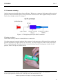
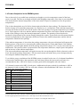
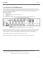
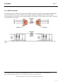
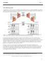
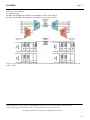
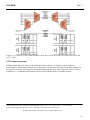
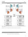
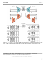
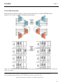
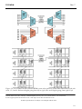
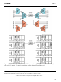
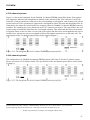
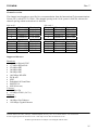
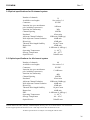
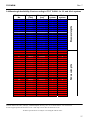
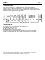
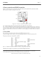
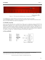
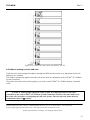
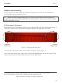
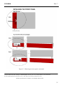
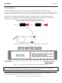
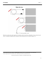
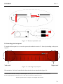
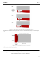
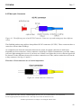
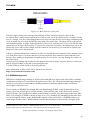
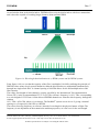
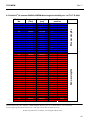
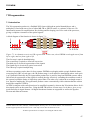
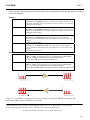


![取扱説明書[PDF:3.6MB]](http://vs1.manualzilla.com/store/data/006628547_3-e54ea06345f6aab36157749c619a5a32-150x150.png)