1
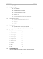
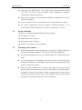
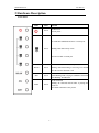
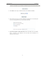
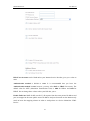
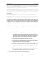
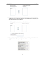
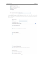
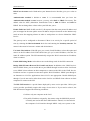
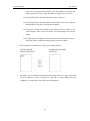
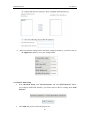
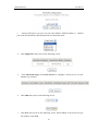
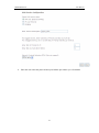
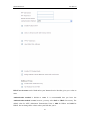
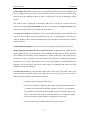
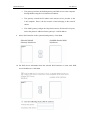
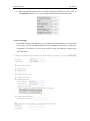
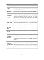
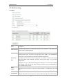
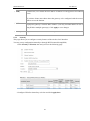
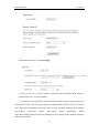
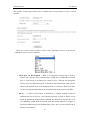
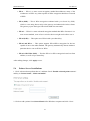
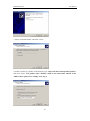
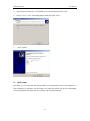
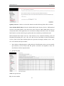
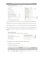
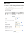
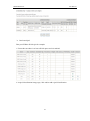
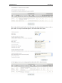
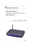
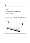
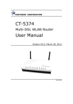
KW5212 Wireless VDSL Router User Manual Kasda Networks Inc. 深圳市宏成数字科技股份有限公司 WLAN VDSL Router User Manual NOTICE This document contains proprietary information protected by copyright, and this Manual and all the accompanying hardware, software, and documentation are copyrighted. All rights are reserved. No part of this document may be photocopied or reproduced by mechanical, electronic, or other means in any form. The manufacturer does not warrant that the hardware will work properly in all environments and applications, and makes no warranty or representation, either expressed or implied, with respect to the quality, performance, merchantability, or fitness for a particular purpose of the software or documentation. The manufacturer reserves the right to make changes to the hardware, software, and documentation without obligation to notify any person or organization of the revision or change. All brand and product names are the trademarks of their respective owners. © Copyright 2014 All rights reserved. WLAN VDSL Router User Manual Content 1 OVERVIEW............................................................................................................................... 1 1.1 FEATURES ............................................................................................................................ 1 1.1.1 Data Rate .............................................................................................................. 1 1.1.2 VDSL Compliant .................................................................................................. 1 1.1.3 Wireless................................................................................................................. 1 1.1.4 Network Protocol & Features .............................................................................. 1 1.1.5 ATM Capabilities ................................................................................................. 2 1.1.6 FIREWALL ........................................................................................................... 2 1.1.7 Management Support .......................................................................................... 3 1.1.8 Operating System Support .................................................................................. 3 1.1.9 Environmental ...................................................................................................... 3 1.2 PACKET CONTENTS........................................................................................................... 3 1.3 SYSTEM REQUIREMENTS.................................................................................................. 3 1.4 FACTORY DEFAULTS ......................................................................................................... 4 1.5 WARNINGS AND CAUTIONS .............................................................................................. 4 2 HARDWARE DESCRIPTION ................................................................................................ 5 3 HARDWARE INSTALLATION.............................................................................................. 7 4 PC CONFIGURATION GUIDE ............................................................................................. 8 5 4.1 LOCAL PC CONFIGURATION IN WINDOWS 95, 98, ME, XP,7 ............................................ 8 4.2 LOCAL PC CONFIGURATION IN WINDOWS 2000 ................................................................. 8 WEB-BASED MANAGEMENT GUIDE ............................................................................... 9 5.1 LAN SETTING PAGE ............................................................................................................ 9 5.2 INTERNET ACCESS CONFIGURATION ............................................................................. 10 5.2.1 ADSL Setup ........................................................................................................ 10 5.2.2 VDSL Setup ........................................................................................................ 15 5.2.3 Router Mode Setup ............................................................................................. 19 5.2.4 LAN Settings ...................................................................................................... 25 5.3 WIRELESS SETTING .......................................................................................................... 27 5.3.1 Basic .................................................................................................................... 27 5.3.2 Security ............................................................................................................... 28 5.4 6. PRINTER SERVER INSTALLATIONS ................................................................................... 31 QOS SETUP ........................................................................................................................... 33 APPENDIX : FREQUENT ASKED QUESTIONS ................................................................ 43 WLAN VDSL Router User Manual 1 Overview Thank you for choosing our product. The product is a Wireless VDSL router combining an VDSL modem, an 802.11n wireless router ,a 4-port switch and an USB port in one unit, bringing high-speed wireless Internet connection to a home or office. 1.1 Features 1.1.1 Data Rate Downstream data rate up to 100 Mbps Upstream data rate up to 50Mbps 1.1.2 VDSL Compliant ITU G.992.1 (G.DMT) ITU G.993.2 (G.vdsl2) (Profile 8a, 8b, 8c, 8d, 12a,12b and 17a) ITU G.992.2 (G.Lite) ITU G.994.1 (G.hs) ITU G.992.3 (G.DMT.BIS) ITU G.992.4 (G.lite.bis) ITU G.992.5 Compatible with all T1.413 issue 2 (full rate DMT over analog POTS), and CO DSLAM equipment 1.1.3 Wireless Fully IEEE 802.11n compatible. Wireless data rate up to 300Mbps Operating in the unlicensed 2.4 GHz ISM band Multi-SSID Supports 64/128 bits WEP security and user authentication 1.1.4 Network Protocol & Features Ethernet to ADSL Self-Learning Transparent Bridging Internet Control Message Protocol (ICMP) 1 WLAN VDSL Router User Manual IP Static Routing Routing Information Protocol (RIP, RIPv2) Network Address Translation (NAT) Virtual Server, Port Forwarding Dynamic Host Configuration Protocol (DHCP) DNS Relay, DDNS IGMP Proxy Simple Network Time Protocol (SNTP) VPN pass-through (IPSec/PPTP/L2TP) Parent control 1.1.5 ATM Capabilities RFC 1483 Multi-protocol over ATM “Bridged Ethernet” compliant RFC 2364 PPP over ATM compliant RFC 2516 PPP over Ethernet compliant ATM Forum UNI3.1/4.0 PVC – Support up to 16 PVCs VPI Range: 0-255 VCI Range: 32-65535 UNI 3.0 & 3.1 Signaling ATM AAL5 (Adaption Layer type 5) OAM F4/F5 1.1.6 FIREWALL Built-in NAT MAC Filtering Packet Filtering Stateful Packet Inspection (SPI) Denial of Service Prevention (DoS) 2 WLAN VDSL Router User Manual 1.1.7 1.1.8 1.1.9 Management Support Web Based GUI Upgrade or update via FTP/HTTP Command Line Interface via Telnet Diagnostic Test Firmware upgradeable for future feature enhancement Operating System Support WINDOWS 98/98 SE/ME/2000/XP/VISTA/7 Macintosh LINUX Environmental Operating humidity: 10%-90% non-condensing 1.2 DMZ Non-operating storage humidity: 5%-95% non-condensing Packet Contents The packet contents are as the following: VDSL ROUTER x1 External Splitter x1 Power Adapter x1 Telephone Line x1 Ethernet Cable x1 Antenna x2 Base x1 CD 1.3 x1 System Requirements Before using this ROUTER, verify that you meet the following requirements: 3 WLAN VDSL Router User Manual Subscription for ADSL service. Your ADSL service provider should provide you with at least one valid IP address (static assignment or dynamic assignment via dial-up connection). One or more computers, each contains an Ethernet 10/100M Base-T network interface card (NIC). A hub or switch, if you are connecting the device to more than one computer. For system configuration using the supplied web-based program: A web browser such as Internet Explorer v5.0 or later, or Netscape v4.7 or later. 1.4 Factory Defaults The device is configured with the following factory defaults: IP Address: 192.168.1.1 Subnet Mask: 255.255.255.0 Encapsulation: RFC 2516 LLC VPI/VCI: According to local information 1.5 Warnings and Cautions Never install telephone wiring during storm. Avoid using a telephone during an electrical storm. There might be a risk of electric shock from lightening. Do not install telephone jacks in wet locations and never use the product near water. To prevent dangerous overloading of the power circuit, be careful about the designed maximum power load ratings. Not to follow the rating guideline could result in a dangerous situation. Please note that telephone line on modem must adopt the primary line that directly outputs from junction box. Do not connect Router to extension phone. In addition, if your house developer divides a telephone line to multi sockets inside the wall of house, please only use the telephone that has connected with the splitter of ADSL Router when you access the Internet. 4 WLAN VDSL Router User Manual 2 Hardware Description Front Panel LED Color Function Green On: Power on Off: No power On: LAN link established and active via LAN port Green Blinking: DSL data activity occurs Off: No LAN link via LAN port On: The wireless module is ready and idle WLAN Green Blinking: Data transmitting or receiving over WLAN Off: The wireless function is off DSL INET Green On: DSL link established and active Quick Blinking: DSL is trying to establish a connection Slow Blinking: No DSL link Green On: IP connected Blinking: IP connected and IP traffic is passing thru this device Off: ADSL connnetion is not present 5 WLAN VDSL Router User Manual Rear panel Port DSL ETH1,2,3,4 Function Connect the device to an DSL telephone jack or splitter using a RJ-11 telephone cable Connect the device to your PC's Ethernet port, or to the uplink port on your hub/switch, using a RJ-45 cable Connect the device to a printer ON/OFF Switch it on or off POWER Connect to the supplied power adapter Side panel WIFI button: Enable or disable wireless function. Reset button: System reset or reset to factory defaults. WPS button: A convenient way for WPS set. 6 WLAN VDSL Router User Manual 3 Hardware Installation This chapter shows you how to connect Router. Meanwhile, it introduces the appropriate environment for the Router and installation instructions. 1. Using a telephone line to connect the DSL port of ROUTER to the MODEM port of the splitter, and using a other telephone line connect your telephone to the PHONE port of the splitter, then connect the wall phone jack to the LINE port of the splitter. The splitter comes with three connectors as below: LINE: Connects to a wall phone jack (RJ-11 jack) MODEM: Connects to the DSL jack of ROUTER PHONE: Connects to a telephone set 2. Using an Ethernet Cable to connect the LAN port of the ROUTER to your LAN or a PC with network card installed. 3. Connect the power cable to the PWR connector on ROUTER, then plug in the power adapter to the power outlet, and then press the on-off button. Notes: Without the splitter and certain situation, transient noise from telephone can interfere with the operation of the Router, and the Router may introduce noise to the telephone line. To prevent this from happening, a small external splitter must be connected to each telephone. 7 WLAN VDSL Router 4 4.1 User Manual PC Configuration Guide Local PC Configuration in Windows 95, 98, ME, XP,7 1. In the Windows task bar, click the “Start” button, point to “Settings”, and then click “Control Panel”. 2. Double-click the “Network” icon. 3. On the “Configuration” tab, select the TCP/IP network associated with your network card and then click “Properties”. 4. In the “TCP/IP Properties” dialog box, click the “IP Address” tab. Set the IP address as 192.168.1.x (x can be a decimal number from 2 to 254.) like 192.168.1.2, and the subnet mask as 255.255.255.0. 5. On the “Gateway” tab, set a new gateway as 192.168.1.1, and then click “Add”. 6. Configure the “DNS” tab if necessary. For information on the IP address of the DNS server, please consult with your ISP. 4.2 7. Click “OK” twice to confirm and save your changes. 8. You will be prompted to restart Windows. Click “Yes”. Local PC Configuration in Windows 2000 1. In the Windows task bar, click the “Start” button, point to “Settings”, and then click “Control Panel”. 2. Double-click the “Network and Dial-up Connections” icon. 3. In the “Network and Dial-up Connections” window, right-click the “Local Area Connection” icon, and then select “Properties”. 4. Highlight “Internet Protocol (TCP/IP)”, and then click “Properties”. 5. In the “Internet Protocol (TCP/IP) Properties” dialog box, set the IP address as 192.168.1.x (x can be a decimal number from 2 to 254.), and the subnet mask as 255.255.255.0 and the default gateway as 192.168.1.1. Then click “OK”. 6. Configure the “DNS” tab if necessary. For information on the IP address of the DNS server, please consult with your ISP. 7. Click “OK” twice to confirm and save your changes. 8 WLAN VDSL Router 5 User Manual Web-based Management Guide In order to use the web-based management software it will be necessary to use a computer that occupies the same subnet as the Router. The simplest way to do this for many users will be to use DHCP server that is enabled by default on the Router. 5.1 LAN setting page Launch a web browser, such as Internet Explorer, and then use http://192.168.1.1 to log on to the setting pages. Enter username ‘admin’ and password ‘adslroot’ Click OK After log on ,you will see the following screen : 9 WLAN VDSL Router We can select User Manual wizard setup or advanced setup mode to setup KW5212.the wizard set up will guide us for a basic setting,and the advanced setup will guide us to home page for more detailed setup. 5.2 Internet Access Configuration 5.2.1 ADSL Setup From home page, you can find Advanced Setup option on the left router configuration page. 1. From Layer2 Interface, click ATM Interface. you can set it up according to the following steps. You Choose Add, or Remove to configure DSL ATM interfaces. 2. Click Add to configure PVC identifier, select DSL latency and select connection mode according to your local occasion. After the configuration, you need to click Apply/Save. 3. Click WAN Service from the left menu. 10 WLAN VDSL Router User Manual 4. Click Add to select a layer 2 interface for this service and then click Next. 5. Choose WAN service type, just choose PPPoE for example here. You can enter your own service description here if you want and then click Next. 6. Input PPP Username & PPP Password and then click Next. The user interface allows a maximum of 256 characters in the user name and a maximum of 32 characters in the password. 11 WLAN VDSL Router User Manual PPPoE service name can be blank unless your Internet Service Provider gives you a value to enter. Authentication method is default to Auto. It is recommended that you leave the Authentication method in Auto, however, you may select PAP or CHAP if necessary. The default value for MTU (Maximum Transmission Unit) is 1500 for PPPoA and 1492 for PPPoE. Do not change these values unless your ISP asks you to. Enable Full Cone NAT: In full cone NAT, all requests from the same private IP address and port are mapped to the same public source IP address and port. Someone on the Internet only needs to know the mapping scheme in order to send packets to a device behind the VDSL Device. 12 WLAN VDSL Router User Manual The gateway can be configured to disconnect if there is no activity for a specific period of time by selecting the Dial on demand check box and entering the Inactivity timeout. The entered value must be between 1 minute and 4320 minutes. Use Static IPv4 address: If the ISP gave you a static (fixed) IP address, select this option and enter it in the IP Address field. If the ISP did not give you a static IP address, clear the Use Static IP Address option. The ISP automatically assigns the WAN connection an IP address when it connects. Enable PPP Debug Mode: Select this to turn on the debug mode for the PPP connection. Bridge PPPoE Frames Between WAN and Local Ports: In addition to the VDSL Device's built-in PPPoE client, you can enable this to pass PPPoE through in order to allow LAN hosts to use PPPoE client software on their computers to connect to the ISP via the VDSL Device. Each host can have a separate account and a public WAN IP address. PPPoE pass through is an alternative to NAT for applications where NAT is not appropriate. Disable PPPoE pass through if you do not need to allow hosts on the LAN to use PPPoE client software on their computers to connect to the ISP. The PPP IP Extension is a special feature deployed by some service providers. Unless your service provider specifically requires this setup, do not select it. If you need to select it, the PPP IP Extension supports the following conditions: It allows only one computer on the LAN. The public IP address assigned by the remote using the PPP/IPCP protocol is actually not used on the WAN PPP interface. Instead, it is forwarded to the computer's LAN interface through DHCP. Only one system on the LAN can be connected to the remote, since the DHCP server within the ADSL gateway has only a single IP address to assign to a LAN device. NAPT and firewall are disabled when this option is selected. The gateway becomes the default gateway and DNS server to the computer through DHCP using the LAN interface IP address. The gateway extends the IP subnet at the remote service provider to the LAN computer. That is, the PC becomes a host belonging to the same IP subnet. The ADSL gateway bridges the IP packets between WAN and LAN ports, unless the packet is addressed to the gateway's LAN IP address. 7. Select a preferred wan interface as the system default gateway. 13 WLAN VDSL Router User Manual 8. Get DNS server information from the selected WAN interface or enter static DNS server IP addresses. If only a single PVC with IPoA or static MER protocol is configured, you must enter static DNS server IP addresses. 9. Make sure that the settings below match the settings provided by your ISP. Click on the Apply/Save button to save your configurations. 14 WLAN VDSL Router User Manual 5.2.2 VDSL Setup From home page, you can find Advanced Setup option on the left router configuration page. 1. From Layer2 Interface, click PTM Interface. you can set it up according to the following steps. You Choose Add, or Remove to configure DSL PTM interfaces. 2.Click Add to configure PTM Priority, select DSL latency and select connection mode according to your local occasion. After the configuration, you need to click Apply/Save. 3. Click WAN Service from the left menu. 4.Click Add to select a layer 2 interface for this service and then click Next. 5. Choose WAN service type, just choose PPPoE for example here. You can enter your own service description here if you want and then click Next. 15 WLAN VDSL Router User Manual 6. Input PPP Username & PPP Password and then click Next. The user interface allows a maximum of 256 characters in the user name and a maximum of 32 characters in the password. 16 WLAN VDSL Router User Manual PPPoE service name can be blank unless your Internet Service Provider gives you a value to enter. Authentication method is default to Auto. It is recommended that you leave the Authentication method in Auto, however, you may select PAP or CHAP if necessary. The default value for MTU (Maximum Transmission Unit) is 1500 for PPPoA and 1492 for PPPoE. Do not change these values unless your ISP asks you to. Enable Full Cone NAT: In full cone NAT, all requests from the same private IP address and port are mapped to the same public source IP address and port. Someone on the Internet only needs to know the mapping scheme in order to send packets to a device behind the VDSL Device. The gateway can be configured to disconnect if there is no activity for a specific period of time by selecting the Dial on demand check box and entering the Inactivity timeout. The entered value must be between 1 minute and 4320 minutes. Use Static IPv4 address: If the ISP gave you a static (fixed) IP address, select this option and enter it in the IP Address field. If the ISP did not give you a static IP address, clear the Use Static IP Address option. The ISP automatically assigns the WAN connection an IP address when it connects. Enable PPP Debug Mode: Select this to turn on the debug mode for the PPP connection. Bridge PPPoE Frames Between WAN and Local Ports: In addition to the VDSL Device's built-in PPPoE client, you can enable this to pass PPPoE through in order to allow LAN hosts to use PPPoE client software on their computers to connect to the ISP via the VDSL Device. Each host can have a separate account and a public WAN IP address. PPPoE pass through is an alternative to NAT for applications where NAT is not appropriate. Disable PPPoE pass through if you do not need to allow hosts on the LAN to use PPPoE client software on their computers to connect to the ISP. The PPP IP Extension is a special feature deployed by some service providers. Unless your service provider specifically requires this setup, do not select it. If you need to select it, the PPP IP Extension supports the following conditions: It allows only one computer on the LAN. The public IP address assigned by the remote using the PPP/IPCP protocol is actually not used on the WAN PPP interface. Instead, it is forwarded to the computer's LAN interface through DHCP. Only one system on the 17 WLAN VDSL Router User Manual LAN can be connected to the remote, since the DHCP server within the ADSL gateway has only a single IP address to assign to a LAN device. NAPT and firewall are disabled when this option is selected. The gateway becomes the default gateway and DNS server to the computer through DHCP using the LAN interface IP address. The gateway extends the IP subnet at the remote service provider to the LAN computer. That is, the PC becomes a host belonging to the same IP subnet. The ADSL gateway bridges the IP packets between WAN and LAN ports, unless the packet is addressed to the gateway's LAN IP address. 7. Select a preferred wan interface as the system default gateway. 8. Get DNS server information from the selected WAN interface or enter static DNS server IP addresses. If only a single PVC with IPoA or static MER protocol is configured, you must enter static DNS server IP addresses. 18 WLAN VDSL Router 9. User Manual Make sure that the settings below match the settings provided by your ISP. Click on the Apply/Save button to save your configurations. 5.2.3 Router Mode Setup 1. From Advanced Setup, click Layer2 Interface and select ETH Interface. Before you configure ETH WAN interface, you’d better remove all PVC settings from ATM interface. 2. Click Add and you’ll see the following screen. 19 WLAN VDSL Router 3. User Manual Select a ETH port as you will. You can select ENET1, ENET2, ENET3 or ENET4 port as the WAN interface and Default mode as connection mode. 4. Click Apply/Save and you’ll see the following screen. 5. From Advanced Setup, click WAN Service to configure a WAN service over the interface you selected. 6. Click Add and you’ll see the following screen. 7. Click Next and you’ll see the following screen. Select PPPoE as WAN service type for example. Click Next. 20 WLAN VDSL Router User Manual 8. Enter the user name and password that your ISP has provided to you. Click Next. 21 WLAN VDSL Router User Manual PPPoE service name can be blank unless your Internet Service Provider gives you a value to enter. Authentication method is default to Auto. It is recommended that you leave the Authentication method in Auto, however, you may select PAP or CHAP if necessary. The default value for MTU (Maximum Transmission Unit) is 1500 for PPPoA and 1492 for PPPoE. Do not change these values unless your ISP asks you to. 22 WLAN VDSL Router User Manual Enable Full Cone NAT: In full cone NAT, all requests from the same private IP address and port are mapped to the same public source IP address and port. Someone on the Internet only needs to know the mapping scheme in order to send packets to a device behind the VDSL Device. The gateway can be configured to disconnect if there is no activity for a specific period of time by selecting the Dial on demand check box and entering the Inactivity timeout. The entered value must be between 1 minute and 4320 minutes. Use Static IPv4 address: If the ISP gave you a static (fixed) IP address, select this option and enter it in the IP Address field. If the ISP did not give you a static IP address, clear the Use Static IP Address option. The ISP automatically assigns the WAN connection an IP address when it connects. Enable PPP Debug Mode: Select this to turn on the debug mode for the PPP connection. Bridge PPPoE Frames Between WAN and Local Ports: In addition to the VDSL Device's built-in PPPoE client, you can enable this to pass PPPoE through in order to allow LAN hosts to use PPPoE client software on their computers to connect to the ISP via the VDSL Device. Each host can have a separate account and a public WAN IP address. PPPoE pass through is an alternative to NAT for applications where NAT is not appropriate. Disable PPPoE pass through if you do not need to allow hosts on the LAN to use PPPoE client software on their computers to connect to the ISP. The PPP IP Extension is a special feature deployed by some service providers. Unless your service provider specifically requires this setup, do not select it. If you need to select it, the PPP IP Extension supports the following conditions: It allows only one computer on the LAN. The public IP address assigned by the remote using the PPP/IPCP protocol is actually not used on the WAN PPP interface. Instead, it is forwarded to the computer's LAN interface through DHCP. Only one system on the LAN can be connected to the remote, since the DHCP server within the ADSL gateway has only a single IP address to assign to a LAN device. NAPT and firewall are disabled when this option is selected. 23 WLAN VDSL Router User Manual The gateway becomes the default gateway and DNS server to the computer through DHCP using the LAN interface IP address. The gateway extends the IP subnet at the remote service provider to the LAN computer. That is, the PC becomes a host belonging to the same IP subnet. The ADSL gateway bridges the IP packets between WAN and LAN ports, unless the packet is addressed to the gateway's LAN IP address. 9. Select WAN interface as the system default gateway. Click Next. 10. Get DNS server information from the selected WAN interface or enter static DNS server IP addresses. Click Next. 24 WLAN VDSL Router User Manual 11. Make sure that the settings below match the settings provided by your ISP. Click on the Apply/Save button to save your configurations and reboot the ADSL router. 5.2.4 LAN Settings From LAN, Configure the DSL Router’s IP Address and Subnet Mask for LAN interface. In this page, you can use DHCP (Dynamic Host Configuration Protocol) to control the assignment of IP addresses on your local network (LAN only).KW5212 support IPv4 /IPv6 dual stack. 25 WLAN VDSL Router Item IP address Subnet mask User Manual Description This is the IP address that other devices on your local network will use to connect to the modem. This defines the size of your network. The default is 255.255.255.0. IGMP Snooping is a method that actually “snoops” or inspects IGMP Enable IGMP snooping traffic on a switch. When enabled, the switch will watch for IGMP messages passed between a host and a router, and will add the necessary ports to its multicast table, ensuring that only the ports that require a given multicast stream actually receive it. The DHCP server assigns an IP addresses from a pre-set pool of Disable / Enable addresses upon request from DHCP client (e.g. your computer). Do not DHCP server disable the DHCP server unless you wish to let another device handle IP address issuance on the local network. Start / end IP address Lease time This is the beginning and ending range for the DHCP server addresses. The amount of time before the IP address is refreshed by the DHCP server. If NAT is disabled and the PVC is the IPoA or static MER type, this Enable DHCP server relay item allows you to inform the router of another DHCP server on your LAN. To do this, disable the DHCP server on the gateway. Then input the IP address of the current DHCP server. Click Apply and restart the gateway. Use this feature to create a public network on your local LAN, Configure the accessible from the Internet. By assigning an address to this interface second IP address and then statically setting your LAN clients to the same network, the and... LAN clients are accessible from the public network (e.g. FTP or HTTP servers). 26 WLAN VDSL Router User Manual 5.3 Wireless setting 5.3.1 Basic Option Enable wireless Hide Access Point Clients isolation Network name Description A checkbox that enables or disables the wireless LAN interfaces. The default is to enable wireless communications. Select Hide Access Point to protect the ADSL route access point from detection by wireless active scans. If you do not want the access point to be automatically detected by a wireless station, this checkbox should be deselected. The station will not discover this access point. To connect a station to the access point, the station must manually add this access point name in it's wireless configuration. In Windows XP, go to the Network>Properties function to view all of the available access points. You can also use other software programs such as NetStumbler to view available access points. Enable this item if you don’t want your wireless clients to communicate with each other. Enter a name for user’s wireless network here. SSID stands for Service Set Identifier. This name must be between 1 and 32 characters long. The default name is 27 WLAN VDSL Router User Manual KASDAxxxx (xxxx means the mac address of KW5212 with uppercase and without (SSID) colon) . All wireless clients must either detect the gateway or be configured with the correct SSID to access the Internet. BSSID Displays the gateway's wireless MAC address. (User may need this address if user is using WDS or multiple gateways.) Click Apply to save changes. Country 5.3.2 Drop-down menu that allows selection of specific channel. Security This page allows you to configure security features of the wireless LAN interface. You may set up configuration manually or through WiFi Protected Setup(WPS) 1.Click Security of Wireless item and you’ll see the following page. 2.Configure WPA Pre-shared key as below and click Apply/Save. 28 WLAN VDSL Router User Manual 3.Enable WPS as below. click Save/Apply 4.. Now you can use a wireless adaptor with WPS function and the WPS button to connect KW5212 to access the Internet. 5. To configure security features for the Wireless interface, please open Security item from Wireless menu. This web page offers nine authentication protocols for user to secure user’s data while connecting to networks. There are four selections including Open, Shared, 802.1X,WPA, WPA-PSK, WPA2, WPA2-PSK, Mixed WPA-WPA2, Mixed WPA-WPA2-PSK. Different item leads different web page settings. Please read the following information carefully. 29 WLAN VDSL Router User Manual The wireless security page allows user to configure the security features of user’s wireless network. There are several security methods to choose from, depending on user’s needs and the capabilities of user’s wireless machines. WEP open and WEP shared —WEP is an encryption scheme that is used to protect user’s wireless data communications. WEP uses a combination of 64-bit keys or 128-bit keys to provide access control to user’s network and encryption security for every data transmission. To decode a data transmission, each wireless client on the network must use an identical 64-bit or 128-bit key. WEP is an older wireless encryption method that is not as hard to break as the more-recent WPA. 802.1x — In 802.1x (also known as RADIUS), a separate machine called an authentication server receives a user ID and password. It grants or denies access based on whether the ID and password match any entries in its account list. User can optionally enable WEP encryption with this option. Because it requires a separate machine acting as the authentication server, 802.1x is most often used in business environments. 30 WLAN VDSL Router User Manual WPA — WPA is a more recent encryption method that addresses many of the weaknesses in WEP. Any client capable of WPA encryption should use it instead of WEP. WPA (PSK) — This is WPA encryption combined with a pre-shared key (PSK), which is a text string known only to the gateway and authorized wireless clients. The gateway rejects the login if the client's PSK does not match. WPA2 — WPA2 is a more advanced encryption method than WPA. Because it is a more recent standard, some of user’s wireless devices might not be able to use it. WPA2 (PSK) — This option uses WPA2 with a pre-shared key. WPA2 and WPA — This option supports WPA2/WPA encryption for devices capable of one or the other standard. The gateway automatically detects whether a particular device can use WPA2 or WPA. WPA2 AND WPA (PSK) — This has WPA2 or WPA encryption based on client abilities, as well as a pre-shared key. After making changes, click Apply to save. 5.4 Printer Server Installations 1. Click “Advanced setupPrint Server” and then Check “Enable on-board printer server” and key in “Printer name”, “Make and model” . 2. Click on Add a printer from Control Panel of the Windows computer and click “Next”. 31 WLAN VDSL Router User Manual 3. Select “Network Printer” and click “Next”. 4. Select Connect to a printer on the Internet, type “http://192.168.1.1:631/printers/printer” and click “Next”. The printer name “Printer” must be the same name entered in the ADSL router “print server setting” as in step 1. 32 WLAN VDSL Router 5. User Manual Select driver file directory on CD-ROM or in your hard disk and click “OK”. 6. Choose “Yes” or “No” for default printer setting and click “Next”. 7. Click “Finish”. 6. QoS setup QoS helps you to control the data upload traffic of each application from LAN (Ethernet) to WAN (Internet). It facilitates you the features to control the quality and speed of throughput for each application when the system is running with full upstream load. 33 WLAN VDSL Router User Manual Quality of Service: Check to activate this function and the following field will be available. Select Default DSCP Mark: Select the default DSCP mark from the list-box. Differentiated Services Code Point (DSCP) is the first 6 bits in the ToS byte. DSCP Mark allows users to classify the traffic of the application to be executed according to the DSCP value. The default DSCP mark is used to mark all egress packets that do not match any classification rules. DSCP indicates three kinds of service, Class Selector (CS), Assured Forwarding (AF) and Expedited Forwarding (EF). AF1, AF2, AF3 and AF4 are four kinds of assured forwarding services. Each AF has three different packet loss priorities from high, medium, to low. Also, CS1-CS7 indicates the IP precedence. Note: Before configuring Queue config and QoS Classification section, you must enable QoS function, for the reason that the queues’ activation will depend on this, the classification will also depend on this. QoS queue setup Name: the queue name. Key: the item number. 34 WLAN VDSL Router User Manual Interface: the queue interface. Scheduler Algorithm: the QoS Scheduler Algorithm, SP(Strict Priority) or WFQ(Weight Fair Queuing) Precedence: the priority identification. Weight: the weight value, 1-63. the highest is 63. PTM Priority: the PTM priority, normal or high. Enable: check the enable check-box, then press Enable to activate the queue. If you want to disable this queue, you can uncheck the corresponding check-box and press Enable, the queue will be disabled. To add a queue, click the Add button, you will see the following page. Input a queue name as you want and select a interface depending your need.decide the priority of the interface. (lower value, higher priority).click apply/save button. QoS Classification Setup You can add or remove a rule. Click add button you will see the following page. 35 WLAN VDSL Router User Manual Parameters Traffic Class Name: Assign a name for this class to uniquely identify the others among multiple classes. Rule Order: Select the priority for this class rule. Rule Status: Select Enable to activate this class rule. Specify Classification Criteria The following parameters are to be classification rule. Enter or select appropriate parameters on the following fields. A blank criterion indicates it is not used for classification. Class Interface: select the interface you want to be the one aspect of the classification criteria. Here ”LAN” and ”WAN” can be viewed as IP QoS, the others can be viewed as ported based QoS, which means that control the QoS of certain port such. For example, if you select ETH0 port, then criteria applies to this port, that is ported-based QoS. Entry Type: select the application type. Source/destination MAC Address: enter the source and destination MAC address as the QoS 36 WLAN VDSL Router User Manual Classification Criteria. The format should be xx:xx:xx:xx:xx:xx Source/destination MAC Mask: MAC mask is similar to IP mask, and the format also should be xx:xx:xx:xx:xx:xx. It is used to hide some information of the MAC address. ‘1’,means needed and ‘0’ means ignored. For example, MAC address e0:3b:4a:c2:ca:e2 and MAC mask ff:ff:ff:00:00:00, that is whatever MAC address while matches e0:3b:4a:XX:XX:XX, will be accepted. Specify Classification Results Enter or select appropriate parameters you want for the packets matched the above classification criteria in the following fields. You have to choose a classification queue. A blank mark or tag value means no change. Specify Classification Queue: assign classification queue from the drop-down box. If you want to select the queue, you should make sure the specific queue is enabled in Queue Config section. Mark Differentiated Service Code Point (DSCP): select the DSCP you want to be the new DSCP for the packets which matched the above classification criteria. Mark 802.1p priority: it is a LAN Layer 2 QoS/CoS Protocol for Traffic Prioritization. It is interoperable with IEEE 802.1Q. 802.1p has 8 kinds of priority. Note: 802.1p/vlan tag feature be supported only when in bridge mode, DSL WAN interface. IP QoS LAN to WAN IP QoS 1. It is a QoS controlling the traffic from LAN to WAN. So first make sure there is at least one WAN queue. If you have configured WAN interface and it will appeared as a default queue, you can also add other queues of the specific interface. See Queue Config. Here we have a atm0 (WAN interface), the interface has a default queue. Make sure to enable the queue. 37 WLAN VDSL Router User Manual 2. In QoS Classification Setup page, Click Add to add a QoS Classification. Then in the appeared Add Network Traffic Class Rule page, enter the information to set up a rule. 1) Specify the rule name, rule order, and rule status. 2) Specify the classification criteria. Here you can set every parameter to strictly control the specific traffic or you can set several parameters to let them be the key elements to control the traffic. A blank criterion indicates it is not used for classification. 38 WLAN VDSL Router User Manual 3) Specify the classification results. Here you must Assign Classification Queue. Whether the following parameters are needed is according to your needs. If you do not want to change the original information, please leave it empty. The queues listed here in the Assign Classification Queue are WAN interface queues set in Queue Config section. Select the needed queue. If you find none queues here, turn back to check whether you have configured a queue and enable it. 3. Click Apply to save your settings. The added rule will listed as below. 39 WLAN VDSL Router User Manual WAN to LAN IP QoS 1. Here we take WAN to LAN (ETH1) QoS for example. Make sure there are enabled port ETH1 based queues here. LAN queues need your configuration. You can enable wireless to enable WMM queues by default or add ETH0-ETH4 ported based queues manually. 2. In QoS Classification Setup page, Click Add to add a Qos Classification. Then in the Add Network Traffic Class Rule page, enter the information to set up a rule. 3. Click Apply to save your settings. The added rule will be listed as below. 40 WLAN VDSL Router User Manual Port based QoS Take port ETH0 to WAN QoS for example. 1. First make sure there is at least a WAN queue and it is enabled. 2. In QoS Classification Setup page, Click Add to add a QoS Classification. 41 WLAN VDSL Router User Manual Then in the Add Network Traffic Class Rule page, enter the information to set up a rule to your needs. To Assign Classification queue, select the needed WAN queue. 3. Click Apply to save your settings and the added rule will be listed as below. 42 WLAN VDSL Router User Manual Appendix : Frequent Asked Questions Q: A: None of the LEDs are on when you power on the ADSL router? Please make sure what you use is the power adaptor attached with the ADSL router package and checks the connection between the AC power and ADSL router. Q: A: DSL LED does not turn on after connect telephone line? Please make sure what you use is the standard telephone line (as attached with the package), make sure the line is connected correctly and check whether there is poor contact at each interface. Wait for 30 seconds to allow the ADSL router establishes connection with you ADSL operator. Q: DSL LED is in the circulation of slow-flashing and fast-flashing after connecting telephone line? A: This situation means the ADSL router is in the status of failing to establish connection with Central Office. Please check carefully and confirm whether the ADSL router has been installed correctly. Q: A: LAN LED does not turn on after connect Ethernet cable? Please make sure Ethernet cable is connected hub/PC and ADSL router correctly. Then please make sure the PC/hub have been power on. Please make sure that you use parallel network cable to connect UpLink port of hub, or use parallel network cable to connect PC. If connect normal port of hub (not UpLink port), you must use cross-cable. Please make sure that your network cables meet the networking requirements above. Q: A: PC cannot access the Router? Please make sure that all devices communicating with the device must use the same channel (and use the same SSID). Otherwise your PC will not find the wireless Router. Q: A: PC cannot access the Internet? First check whether PC can ping the interface Ethernet IP address of this product successfully (default value is 192.168.1.1) by using ping application. If ping application fails, please check the connection of Ethernet cable and check whether the states of LEDs are in gear. If the PC uses private IP address that is set manually (non-registered legal IP address), please check: 1. Whether IP address of the PC gateway is legal IP address. Otherwise please use the right gateway, or set the PC to Obtain an IP address automatically. 2. Please confirm the validity of DNS server appointed to the PC with ADSL operator. Otherwise please use the right DNS, or set the PC to Obtain an IP address automatically. 3. Please make sure you have set the NAT rules and convert private IP address to legal IP address. IP address range of the PC that you specify should meet the setting range in NAT rules. 4. Central Office equipment may have problem. 5. The country or the wireless network type you selected is wrong. 43 WLAN VDSL Router Q: A: User Manual PC cannot browse Internet web page? Please make sure DNS server appointed to the PC is correct. You can use ping application program to test whether the PC can connect to the DNS server of the ADSL operator. Q: A: Initialization of the PVC connection failed? Be sure that cable is connected properly from the DSL port to the wall jack. The DSL LED on the front panel of the ADSL router should be on. Check that your VPI, VCI, type of encapsulation and type of multiplexing setting are the same as what you collected from your service provider, Re-configure ADSL router and reboot it. If you still cannot work it out, you may need to verify these variables with the service provider. If the cause is not given above, please contact your local service provider! 44