1
Finnigan
GasBench II
™
Operating Manual
Revision A
111 8342
Finnigan™ is a trademark of the Thermo Electron Corporation.
Thermo Electron (Bremen) is part of the Thermo Electron Corporation.
Chrompack® is a registered trademark of Varian, Inc..
SNOOP® is a registered trademark of the NUPRO Company.
Viton® is a registered trademark of DuPont Dow Elastomers.
Teflon® and Nafion® are registered trademarks of the DuPont Company.
Swagelok® is a registered trademark of the Crawford Fitting Company.
Valco™ is a trademark of VICI (Valco Instruments Co. Inc.).
Microsoft®, Windows 95, Windows 98, Windows 2000, Windows NT and Windows XP are trademarks of Microsoft Corporation.
Technical information contained in this publication is for reference purposes only and is subject to change
without notice. Every effort has been made to supply complete and accurate information; however,
Thermo Electron assumes no responsibility and will not be liable for any errors, omissions, damage, or loss
that might result from any use of this manual or the information contained therein (even if this information is
properly followed and problems still arise).
This publication is not part of the Agreement of Sale between Thermo Electron and the purchaser of a
Thermo Electron system. In the event of any conflict between the provisions of this document and those
contained in Thermo Electron Terms and Conditions, the provisions of the Terms and Conditions shall govern.
Reference to System Configurations and Specifications supersede all previous information and are subject to
change without notice.
Printing History: Revision A printed in 9/28/04.
The products of Thermo Electron Bremen are produced under ISO 9001 accredited quality management systems.
Australia: P.O. Box 239 Rydalmere xUnit 14, 38 – 46 South Street x Rydalmere, N.S.W. 2116 x [61] (02) 9898-9000
Austria: Wehlistrasse 27b x A-1200 Wien x [43] (01) 333 50 34-0
Belgium: Technologiestraat 47 x B-1082 Brussels x [32] (02) 482 30 30
Canada: 5716 Coopers Avenue, Unit 1 x Mississauga, Ontario x L4Z 2E8 x [1] (905) 712-2258
France: 16 Avenue du Québec x Silic 765 x Z.A. de Courtaboeuf x F-91963 Les Ulis Cédex x [33] (01) 60 92 48 00
Germany: Im Steingrund 4-6 x D-63303 Dreieich x [49] (06103) 408 0
Italy: Strada Rivoltana x I-20090 Rodano (Milano) x [39] (02) 95059 226
Japan: C-2F x 3-9, Moriya-cho, Kanagawa-ku xYokohama, Kanagawa x221-0022 x [81] (45) 453 9100
Japan: Esaka Grand Building x 2-3-1 Esaka-cho, Suita City x Osaka 564-0063 x [81] (06) 6387-6681
Netherlands: Takkebijsters 1 x4817 BL Breda x [31] (076) 5878 722
P.R. China: Room 901, Ping-an Mansion x No. 23, Jin Rong Street x Xi Cheng District x Beijing 100032 x [86] (010) 6621 0839
Spain: Sepulveda 7 A x ES-28108 Alcobendas (Madrid) x [34] (091) 657 4930
Spain: Acer 30 – 32 x Edificio Sertram – Planta 2, Modulo 3 x ES-08038 Barcelona x [34] (093) 223 0918
Sweden: Pyramidbacken 3 x S-141 75 Kungens Kurva (Stockholm) x [46] (08) 556 468 00
United Kingdom: Stafford House x 1 Boundary Park x Boundary Way xHemel Hempstead x Hertfordshire HP2 7GE x [44] (01442) 233 555
U.S.A.: 355 River Oaks Parkway x San Jose, CA 95134-1991 x [1] (408) 965-6000
Notes: The country code is enclosed in square brackets [ ]. The city code or area code is enclosed in parenthesis ( ). For countries other than the U.S.A.,
when you are dialing from within the specified country, dial the 0 of the city code. For countries other than Italy, when you are dialing from outside the country,
do not dial the 0 of the city code.
Published by Product Marketing, Thermo Electron Corporation, Bremen, Germany.
Copyright© 2004 Thermo Electron Corporation. All rights reserved. Printed in Germany.
Thermo Electron (Bremen) GmbH
Barkhausenstr. 2
D-28197 Bremen
Telefon: +49 (0)421-5493-0
Internet: www.thermo-bremen.com
-----------------------------------------------------------------------------------------------------------------------------------
Reparatur - Begleitkarte
Repair-Covering Letter
Bitte vollständig ausfüllen
Please fill in completely
Absender:
Dispatcher:
Geräte-Type:
Instrument Type:
Service-Nr.:
Service-No.:
----------------------------------------------------------------------------------------------------------------------------------Sie erhalten zur Reparatur unter unserer Bestell-Nr.:
You receive for repair under our Order No.:
------------------------------------------------------------------------------------------------------------------------------------------------------------------------
DOA
Teil wurde nicht benutzt / part not used
Teil wurde nur für Testzwecke verwendet / used for test purposes only
Festgestellte Mängel oder deren Auswirkung:
Established Defect or its Effect:
Bitte detaillierte Angaben machen / Please specify in Detail
--------------------------------------------------------------------------------------------------------------------------------Ein Austauschteil haben wir erhalten unter Kommissions-Nr.:
An Exchange Part already received with Commission No.:
Ja/Yes Nein/No
---------------------------------------------------------------------------------------------------------------------------------Die Anlage ist außer Funktion
The System is out of Function
Ja/Yes Nein/No
---------------------------------------------------------------------------------------------------------------------------------Durch die nachfolgende Unterschrift bestätige(n)
ich/wir, daß die o.g. Teile frei von gesundheits schädlichen Stoffen sind, bzw. vor Ihrer Einsen dung an Thermo Electron Bremen dekontami niert wurden, falls die Teile mit giftigen Stoffen in
Verbindung gekommen sind.
By signing this Document I am/we are certifying
that the a.m. Parts are free from hazardous
materials. In case the parts have been used for
the analysis of hazardous substances I/we
attest that the parts have been decontaminated
before sending them to Thermo Electron
Bremen.
-----------------------------------Datum / Date
-------------------------------------------------------------------Unterschrift / Signature
Customer Registration... Register now and receive all the privileges associated with being a Thermo
Electron, Finnigan product user, including application reports and technical reports.
Name_______________________________________________________________________________________
Title ________________________________________________________________________________________
Company ___________________________________________________________________________________
Address _____________________________________________________________________________________
City/State/Postal Code_________________________________________________________________________
Country ____________________________________________________________________________________
Telephone _____________________________________________ Ext. _________________________________
Tell us more... Let us know more about how you use this product:
My Organization Is: (Check one only)
Commercial (for profit) lab
Government lab
Hospital / Clinic
Research Institute
University / College
Veterinary
Other ___________________________
Job Function: (Check one only)
Administration
Lab Management
Operator
Other ___________________________
My Primary Application Is: (Check one only)
Analytical
Biomedical
Clinical / Toxicology
Energy
Food / Agriculture
Forensic / Toxicology
Pharmaceutical
Research / Education
Other ___________________________
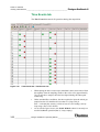
Reader Survey... Help us to improve the quality of our documentation by answering a few questions:
Revision A
111 8342
Finnigan GasBench II Operating Manual
The manual is well organized.
The manual is clearly written.
The manual contains all of the information I need.
The instructions are easy to follow.
The instructions are complete.
The technical information is easy to understand.
The figures are helpful.
Strongly
Agree
Agree
Disagree
Strongly
Disagree
1
1
1
1
1
1
1
2
2
2
2
2
2
2
3
3
3
3
3
3
3
4
4
4
4
4
4
4
Additional Comments: (Attach additional sheets if necessary.)
___________________________________________________________________________________
___________________________________________________________________________________
___________________________________________________________________________________
___________________________________________________________________________________
___________________________________________________________________________________
___________________________________________________________________________________
___________________________________________________________________________________
Tear this sheet from the manual, fold it closed, stamp it, and drop it in the mail.
fold
From ________________________________
_____________________________________
Place
Stamp
Here
_____________________________________
Thermo Electron (Bremen) GmbH
Finnigan Advanced Mass Spectrometry
Product Marketing
Barkhausenstr. 2
D-28197 Bremen
Germany
fold
Notice on the Proper Use of
Thermo Electron Bremen Instruments
In compliance with international regulations: If this instrument is used in a manner not
specified by Thermo Electron Bremen, the protection provided by the instrument could be
impaired.
Safety and EMC Information
In accordance with our commitment to customer service and safety, these
instruments have satisfied the requirements for the European CE Mark
including the Low Voltage Directive.
Designed, manufactured and tested in an ISO9001 registered facility, this
instrument has been shipped to you from our manufacturing facility in a safe
condition.
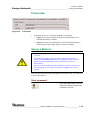
Caution. This instrument must be used as described in this manual. Any use
of this instrument in a manner other than described here may result in
instrument damage and/or operator injury.
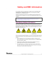
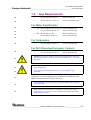
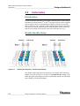
Identifying Safety Information
This reference manual contains precautionary statements that can prevent
personal injury, instrument damage, and loss of data if properly followed. All
statements of this nature are called to your attention through the use of bold
type and the following icons:
Warning!
Cold Surface!
Hot Surface
Strong
Magnetic Field!
High Voltage!
Every instrument has specific hazards, so be sure to read and comply with the
following precautions. They will help ensure the safe, long-term use of your
system.
1. Before plugging in any of the instrument modules or turning on the
power, always make sure that the voltage and fuses are set appropriately
for your local line voltage.
2. Only use fuses of the type and current rating specified. Do not use
repaired fuses and do not short-circuit the fuse holder.
3. The supplied power cord must be inserted into a power outlet with a
protective earth contact (ground). When using an extension cord, make
sure that the cord also has an earth contact.
Thermo ______________________Finnigan GasBench II Operating Manual ___________________ a
ELECTRON CORPORATION
Safety and EMC Information
Identifying Safety Information
_________________________________________ Finnigan GasBench II
4. Do not change the external or internal grounding connections.
Tampering with or disconnecting these connections could endanger you
and/or damage the system.
Caution. The instrument is properly grounded in accordance with
regulations when shipped. You do not need to make any changes to the
electrical connections or to the instrument’s chassis to ensure safe operation.
5. Never run the system without the housing on. Permanent damage can
occur.
6. Do not turn the instrument on if you suspect that it has incurred any kind
of electrical damage. Instead, disconnect the power cord and contact a
Service Representative for a product evaluation. Do not attempt to use the
instrument until it has been evaluated. (Electrical damage may have
occurred if the system shows visible signs of damage, or has been
transported under severe stress.)
7. Damage can also result if the instrument is stored for prolonged periods
under unfavorable conditions (e.g., subjected to heat, water, etc.).
8. Always disconnect the power cord before attempting any type of
maintenance.
9. Never try to repair or replace any component of the system that is not
described in this manual without the assistance of your service
representative.
Warning. Avoid any contact of the system with liquids! Permanent damage
can occur due to high voltage, e.g. leaking liquids might get into contact
with electronic components and cause a short circuit.
b_______________________ Finnigan GasBench II Operating Manual ____________________
Thermo
ELECTRON CORPORATION
Finnigan GasBench
Contents
II ____________________________________________________________________
Contents
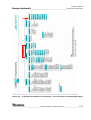
Preinstallation Requirements ................................................................................................... 1-1
1.1
Site and Power Requirements ................................................................................................... 1-2
1.2
Gas Requirements .....................................................................................................................
For Water Equilibration ......................................................................................................
For Carbonates....................................................................................................................
For DIC (Dissolved Inorganic Carbon) ..............................................................................
1-3
1-3
1-3
1-3
Hardware Components ............................................................................................................ 2-1
2.1
GasBench II Layout .................................................................................................................. 2-2
2.2
Autosampler .............................................................................................................................. 2-4
Installing the Autosampler ................................................................................................. 2-5
Connecting the Autosampler .............................................................................................. 2-6
2.3
Sample Trays............................................................................................................................. 2-7
Layout................................................................................................................................. 2-7
Programming JUMO itron 16 Temperature Controller for Sample Tray ......................... 2-11
2.4
Gas Supply ..............................................................................................................................
Gases in Use .....................................................................................................................
Installing the Gas Tanks ...................................................................................................
Working with the Gas Tanks ............................................................................................
Gas Connections...............................................................................................................
2.5
Measurement Needle............................................................................................................... 2-16
How to Connect the Measurement Needle....................................................................... 2-16
2.6
Flush Needle ........................................................................................................................... 2-18
How to Connect the Flush Needle.................................................................................... 2-18
2.7
Mounting Syringe Needles into Autosampler......................................................................... 2-19
2.8
On-Line Water Removal ......................................................................................................... 2-21
Principle of On-Line Water Removal............................................................................... 2-21
2.9
Principle of Valco Eight Port Valve ........................................................................................ 2-22
How to Change the Loop Size.......................................................................................... 2-23
2-13
2-13
2-13
2-14
2-14
Thermo ____________________ Finnigan GasBench II Operating Manual ______________________
ELECTRON CORPORATION
i
Contents
_______________________________________________________________ Finnigan GasBench II
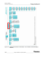
2.10
GC Oven .................................................................................................................................
Type "PoraPlot Q" GC Column .......................................................................................
Type "HayeSep D" GC Column.......................................................................................
Step 1 - Accessing the GC Column .................................................................................
Step 2 - Changing the GC Column ..................................................................................
Programming JUMO itron 16 Temperature Controller for GC Oven..............................
2-26
2-26
2-27
2-27
2-29
2-32
2.11
Open Splits ............................................................................................................................. 2-34
Reference Injection .......................................................................................................... 2-34
Sample Injection and Dilution ......................................................................................... 2-36
Isodat 2.0 Software .................................................................................................................... 3-1
3.1
Starting Isodat 2.0..................................................................................................................... 3-2
3.2
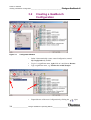
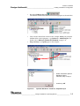
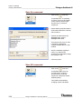
Creating a GasBench Configuration......................................................................................... 3-4
3.3
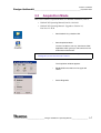
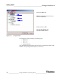
Acquisition Mode ..................................................................................................................... 3-7
3.4
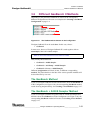
Accessories Bar ........................................................................................................................ 3-9
Troubleshooting - Error Messages ..................................................................................... 3-9
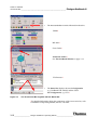
Changing Visibility of its Components............................................................................. 3-11
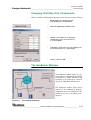
The GasBench Window .................................................................................................... 3-11
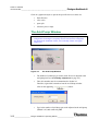
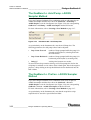
The Acid Pump Window.................................................................................................. 3-12
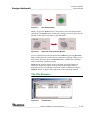
The File Browser.............................................................................................................. 3-13
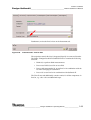
3.5
Creating a New Method..........................................................................................................
Predefined Methods as Examples ....................................................................................
Structure of GasBench Related Methods .........................................................................
Instrument tab ..................................................................................................................
Time Events tab................................................................................................................
Component Names tab .....................................................................................................
Evaluation tab ..................................................................................................................
Peak Detection tab ...........................................................................................................
Printout tab.......................................................................................................................
Saving a Method ..............................................................................................................
3-17
3-18
3-19
3-19
3-22
3-24
3-25
3-26
3-29
3-29
3.6
Different GasBench II Methods .............................................................................................
The GasBench Method.....................................................................................................
The GasBench + A200S Sampler Method.......................................................................
The GasBench + Acid Pump + A200S Sampler Method ................................................
The GasBench + PreCon + A200S Sampler Method.......................................................
3-31
3-31
3-31
3-32
3-32
ii _______________________ Finnigan GasBench II Operating Manual ____________________
Thermo
ELECTRON CORPORATION
Finnigan GasBench
Contents
II ____________________________________________________________________
3.7
Creating a New Sequence .......................................................................................................
Saving a Sequence............................................................................................................
Starting a Sequence ..........................................................................................................
Predefined Sequences as Examples..................................................................................
3-34
3-36
3-38
3-39
3.8
Excel Export............................................................................................................................ 3-41
3.9
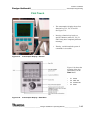
Autosampler Programming .....................................................................................................
GC PAL Loader Software.................................................................................................
First Touch........................................................................................................................
Adjusting Autosampler Tray Position ..............................................................................
Using Autosampler Method .............................................................................................
Testing the Autosampler...................................................................................................
3-42
3-42
3-43
3-49
3-50
3-51
Basic Operations ....................................................................................................................... 4-1
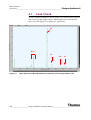
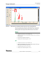
4.1
Leak Check ............................................................................................................................... 4-2
Water................................................................................................................................... 4-3
Air....................................................................................................................................... 4-3
CO2 ........................................................................................................................................................................ 4-4
4.2
Checking Column Flows........................................................................................................... 4-5
4.3
Zero Enrichment Test (Standard On/Off Test).......................................................................... 4-6
Testing Reference Gas Inlet Ports ...................................................................................... 4-9
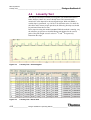
4.4
Linearity Test .......................................................................................................................... 4-10
4.5
Condition Test ......................................................................................................................... 4-12
4.6
Starting an Automated Sequence ............................................................................................ 4-13
Before Starting an Automated Sequence.......................................................................... 4-13
Preparing a Test Sample ................................................................................................... 4-13
4.7
Frequently Asked Questions ................................................................................................... 4-16
Measurement Procedures for Real Samples ........................................................................... 5-1
5.1
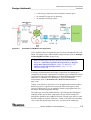
Introduction...............................................................................................................................
General Remarks ................................................................................................................
Headspace Sampling ..........................................................................................................
Cleaning Procedure for Sample Vials.................................................................................
5-2
5-2
5-4
5-5
Thermo ____________________ Finnigan GasBench II Operating Manual _____________________ iii
ELECTRON CORPORATION
Contents
_______________________________________________________________ Finnigan GasBench II
5.2
Carbonates ................................................................................................................................ 5-6
Introduction........................................................................................................................ 5-6
Double Needle Setup ......................................................................................................... 5-6
Carbonates in Brief ............................................................................................................ 5-7
Linearity Correction......................................................................................................... 5-10
Referencing versus VPDB ............................................................................................... 5-13
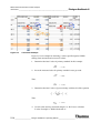
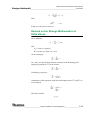
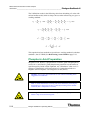
Remark on the Strange Mathematics of Delta Values...................................................... 5-15
Phosphoric Acid Preparation ........................................................................................... 5-16
Adding Phosphorous Pentoxide ....................................................................................... 5-17
Common Pitfalls .............................................................................................................. 5-17
Neogloboquadrina Pachyderma (Ehrenberg, 1894)......................................................... 5-19
5.3
Dissolved Inorganic Carbon (DIC)......................................................................................... 5-20
Dissolved Inorganic Carbon (DIC) in Brief..................................................................... 5-20
5.4
Breath Gas Analysis ...............................................................................................................
Using the Autodiluter for Blanking .................................................................................
Results of Blanking..........................................................................................................
Breath Gas Analysis in Brief ...........................................................................................
Results of Breath Gas Analysis........................................................................................
5.5
CO2 in Atmospheric Concentrations ...................................................................................... 5-28
Editing a Method.............................................................................................................. 5-28
Results.............................................................................................................................. 5-29
5.6
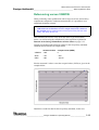
Water Equilibration (18O).......................................................................................................
18
O Equilibration in Brief ................................................................................................
Sample Tray Temperature Control...................................................................................
Referencing versus VSMOW...........................................................................................
Results..............................................................................................................................
5-30
5-30
5-31
5-31
5-32
5.7
Water Equilibration (H/D) ......................................................................................................
H/D Equilibration in Brief ...............................................................................................
Preparing an H/D Measurement.......................................................................................
Referencing versus VSMOW...........................................................................................
Adjusting Electron Energy...............................................................................................
Determining the Optimal Setting of the Electron Energy................................................
Results..............................................................................................................................
Sample Amount Consideration for Both Water Equilibration Types...............................
5-33
5-33
5-34
5-35
5-36
5-37
5-37
5-38
5-24
5-24
5-25
5-26
5-26
Options ....................................................................................................................................... 6-1
iv ______________________ Finnigan GasBench II Operating Manual ____________________
Thermo
ELECTRON CORPORATION
Finnigan GasBench
Contents
II ____________________________________________________________________
6.1
Carbonate Option ......................................................................................................................
Components........................................................................................................................
Acid Pump ..........................................................................................................................
Connecting the Acid Needle...............................................................................................
6-2
6-2
6-3
6-6
6.2
Cryo Traps Option..................................................................................................................... 6-7
Introduction ........................................................................................................................ 6-7
Principle of Operation ........................................................................................................ 6-7
Procedure............................................................................................................................ 6-7
Connecting Cryo Trap ...................................................................................................... 6-11
Notes for GasBench II Trapping System.......................................................................... 6-12
Trapping of N2 at - 196 ºC................................................................................................ 6-14
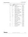
Technical Information .............................................................................................................. 7-1
7.1
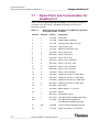
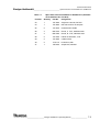
Spare Parts and Consumables for GasBench II ........................................................................ 7-2
7.2
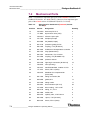
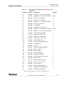
Mechanical Parts ....................................................................................................................... 7-4
7.3
Plug and Measure Adapter........................................................................................................ 7-8
7.4
Capillaries ................................................................................................................................. 7-9
7.5
Water Traps ............................................................................................................................. 7-10
7.6
Reference Open Split .............................................................................................................. 7-12
7.7
Sample Open Split .................................................................................................................. 7-13
7.8
IAEA Primary Standards ........................................................................................................ 7-14
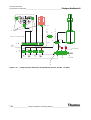
7.9
Compressed Air Schematic..................................................................................................... 7-15
Thermo ____________________ Finnigan GasBench II Operating Manual ______________________ v
ELECTRON CORPORATION
Contents
_______________________________________________________________ Finnigan GasBench II
vi ______________________ Finnigan GasBench II Operating Manual ____________________
Thermo
ELECTRON CORPORATION
Read This First
Welcome to the Thermo Electron, Finnigan GasBench II Operating Manual!
Finnigan GasBench II Operating Manual describes how to setup and use
Finnigan GasBench II.
It includes the following chapters:
Chapter 1: Preinstallation Requirements summarizes requirements related
to site, power and the various gases in use before operating Finnigan
GasBench II.
Chapter 2: Hardware Components treats autosampler installation, sample
tray and its temperature control, gas supply, measurement needle and flush
needle, water removal, valco eight-port valve, GC oven and open splits.
Chapter 3: Isodat 2.0 Software describes how to start Isodat 2.0 and
subsequently how to create a GasBench-related configuration.
Then, the chapter denotes how to create a new GasBench II method and a new
GasBench II sequence in Isodat 2.0’s Acquisition Mode. Various types of
GasBench II methods are demonstrated as examples, including e.g. an
autosampler, an acid pump or a PreCon. Finally, basics of autosampler
programming are discussed.
Chapter 4: Basic Operations describes several test routines, e.g. leak check,
checking column flows, zero enrichment test (that is, standard on/off test),
linearity test and condition test.
The chapter ends pointing out how to start an automated sequence and
summarizing Frequently Asked Questions (FAQ).
Chapter 5: Measurement Procedures for Real Samples deals with
carbonates, Dissolved Inorganic Carbon (DIC), breath gas analysis, CO2 in
atmospheric concentrations and water equilibration (18O and H/D,
respectively).
Chapter 6: Options describes carbonate option and cryo traps option.
Chapter 7: Technical Information outlines test instructions, auxiliary parts
and mechanical parts. It provides technical information about the capillaries
in use and compressed air supply as well.
Thermo ____________________ Finnigan GasBench II Operating Manual _____________________ vii
ELECTRON CORPORATION
Read This First
Changes to the Manual and Online Help
_________________________________ Finnigan GasBench II
Changes to the Manual and Online Help
To suggest changes to this manual or the online Help, please send your
comments to:
Thermo Electron (Bremen) GmbH
Finnigan Advanced Mass Spectrometry
Barkhausenstr. 2
D-28197 Bremen
Germany
You are encouraged to report errors or omissions in the text or index.
Thank you.
viii _____________________ Finnigan GasBench II Operating Manual ____________________
Thermo
ELECTRON CORPORATION
Finnigan GasBench
Read This First
II _________________________________________________________ Abbreviations
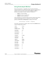
Abbreviations
The following abbreviations are used in this and other manuals and in the
online Help.
A
ampere
ac
alternating current
ADC
analog-to-digital converter
AP
acquisition processor
APCI
atmospheric pressure chemical ionization
API
atmospheric pressure ionization
ASCII
American Standard Code for Information
Interchange
b
bit
B
byte (8 b)
baud rate
data transmission speed in events per second
°C
degrees Celsius
CD
compact disc
CD-ROM
compact disc read-only memory
cfm
cubic feet per minute
CI
chemical ionization
CIP
carriage and insurance paid to
cm
centimeter
cm3
cubic centimeter
CPU
central processing unit (of a computer)
CRC
cyclic redundancy check
CRM
consecutive reaction monitoring
<Ctrl>
control key on the terminal keyboard
d
depth
Da
dalton
DAC
digital-to-analog converter
dc
direct current
DDS
direct digital synthesizer
DEP¥
direct exposure probe
DS
data system
DSP
digital signal processor
Thermo ____________________ Finnigan GasBench II Operating Manual _____________________ ix
ELECTRON CORPORATION
Read This First
Abbreviations _____________________________________________________
Finnigan GasBench II
EI
electron ionization
EMBL
European Molecular Biology Laboratory
<Enter>
enter key on the terminal keyboard
ESD
electrostatic discharge
ESI
electrospray ionization
eV
electron volt
f
femto (10-15)
°F
degrees Fahrenheit
.fasta file
extension of a SEQUEST search database file
FOB
free on board
ft
foot
FTP
file transfer protocol
g
gram
G
giga (109)
GC
gas chromatograph; gas chromatography
GC/MS
gas chromatograph/mass spectrometer
GND
electrical ground
GPIB
general-purpose interface bus
GUI
graphical user interface
h
hour
h
height
HPLC
high-performance liquid chromatograph
HV
high voltage
Hz
hertz (cycles per second)
ICIS¥
Interactive Chemical Information System
ICL¥
Instrument Control Language¥
ID
inside diameter
IEC
International Electrotechnical Commission
IEEE
Institute of Electrical and Electronics Engineers
in.
inch
I/O
input/output
k
kilo (103, 1000)
K
kilo (210, 1024)
KEGG
Kyoto Encyclopedia of Genes and Genomes
kg
kilogram
x _______________________ Finnigan GasBench II Operating Manual ____________________
Thermo
ELECTRON CORPORATION
Finnigan GasBench
Read This First
II _________________________________________________________ Abbreviations
l
length
l
liter
LAN
local area network
lb
pound
LC
liquid chromatograph; liquid chromatography
LC IRMS
liquid chromatography isotope ratio mass
spectrometer
LC/MS
liquid chromatograph/mass spectrometer
LED
light-emitting diode
P
micro (10-6)
m
meter
m
milli (10-3)
M
mega (106)
M+
molecular ion
MB
Megabyte (1048576 bytes)
MH+
protonated molecular ion
min
minute
ml
milliliter
mm
millimeter
MS
mass spectrometer; mass spectrometry
MS
MSn power: where n = 1
MS/MS
MSn power: where n = 2
MSn
MSn power: where n = 1 through 10
m/z
mass-to-charge ratio
n
nano (10-9)
NCBI
National Center for Biotechnology Information
(USA)
NIST
National Institute of Standards and Technology
(USA)
OD
outside diameter
:
ohm
p
pico (10-12)
Pa
pascal
PCB
printed circuit board
PID
proportional / integral / differential
P/N
part number
Thermo ____________________ Finnigan GasBench II Operating Manual _____________________ xi
ELECTRON CORPORATION
Read This First
Abbreviations _____________________________________________________
Finnigan GasBench II
P/P
peak-to-peak voltage
ppm
parts per million
psig
pounds per square inch, gauge
RAM
random access memory
RF
radio frequency
RMS
root mean square
ROM
read-only memory
RS-232
industry standard for serial communications
s
second
SIM
selected ion monitoring
solids probe
direct insertion probe
SRM
selected reaction monitoring
ss
stainless steel
SSQ
single stage quadrupole
TCP/IP
transmission control protocol / Internet protocol
TIC
total ion current
Torr
torr
TSQ
triple stage quadrupole
u
atomic mass unit
URL
uniform resource locator
V
volt
V ac
volts alternating current
V dc
volts direct current
vol
volume
w
width
W
watt
WWW
World Wide Web
Note. Exponents are written as superscripts. In the corresponding online
Help, exponents are sometimes written with a caret (^) or with e notation
because of design constraints in the online Help. For example:
MSn (in this manual) Ms^n (in the online Help)
105 (in this manual)
10^5 (in the online Help)
xii ______________________ Finnigan GasBench II Operating Manual ____________________
Thermo
ELECTRON CORPORATION
Finnigan GasBench
Read This First
II _______________________________________________Typographical Conventions
Typographical Conventions
Typographical conventions have been established for Thermo Electron
San Jose manuals for the following:
•
Data input
•
Boxed information
•
Topic headings
Data Input
Throughout this manual, the following conventions indicate data input and
output via the computer:
•
Messages displayed on the screen are represented by capitalizing the
initial letter of each word and by italicizing each word.
•
Input that you enter by keyboard is represented in bold face letters.
(Titles of topics, chapters, and manuals also appear in bold face letters.)
•
For brevity, expressions such as “choose File > Directories” are used
rather than “pull down the File menu and choose Directories.”
•
Any command enclosed in angle brackets < > represents a single
keystroke. For example, “press <F1>” means press the key labeled F1.
•
Any command that requires pressing two or more keys simultaneously is
shown with a plus sign connecting the keys. For example, “press
<Shift> + <F1>” means press and hold the <Shift> key and then press the
<F1> key.
•
Any button that you click on the screen is represented in bold face letters
and a different font. For example, “click on Close”.
Thermo ____________________ Finnigan GasBench II Operating Manual ____________________ xiii
ELECTRON CORPORATION
Read This First
Typographical Conventions ___________________________________________
Finnigan GasBench II
Boxed Information
Information that is important, but not part of the main flow of text, is
displayed in a box such as the one below.
Note. Boxes such as this are used to display information.
Boxed information can be of the following types:
•
Note – information that can affect the quality of your data. In addition,
notes often contain information that you might need if you are having
trouble.
•
Caution – information necessary to protect your instrument from
damage.
•
Warning – hazards to human beings. Each Warning is accompanied by a
Warning symbol.
xiv _____________________ Finnigan GasBench II Operating Manual ____________________
Thermo
ELECTRON CORPORATION
Finnigan GasBench
Read This First
II _______________________________________________Typographical Conventions
Topic Headings
The following headings are used to show the organization of topics within a
chapter:
Chapter 1
Chapter Name
1.2 Second Level Topics
Third Level Topics
Fourth Level Topics
Fifth Level Topics
Thermo ____________________ Finnigan GasBench II Operating Manual ____________________
ELECTRON CORPORATION
xv
Read This First
Reply Cards ______________________________________________________
Finnigan GasBench II
Reply Cards
Thermo Electron San Jose manuals contain one or two reply cards. All
manuals contain a Customer Registration / Reader Survey card and some
contain a Change of Location card. These cards are located at the front of each
manual.
The Customer Registration / Reader Survey card has two functions. First,
when you return the card, you are placed on the Thermo Electron San Jose
mailing list. As a member of this list, you receive application reports and
technical reports in your area of interest, and you are notified of events of
interest, such as user meetings. Second, it allows you to tell us what you like
and do not like about the manual.
The Change of Location card allows us to track the whereabouts of the
instrument. Fill out and return the card if you move the instrument to another
site within your company or if you sell the instrument. Occasionally, we need
to notify owners of our products about safety or other issues.
xvi _____________________ Finnigan GasBench II Operating Manual ____________________
Thermo
ELECTRON CORPORATION
Chapter 1
Preinstallation Requirements
1.1 Site and Power Requirements
1.2 Gas Requirements
Thermo ____________________ Finnigan GasBench II Operating Manual ___________________
ELECTRON CORPORATION
1-1
Preinstallation Requirements
Site and Power Requirements _________________________________________
1.1
Finnigan GasBench II
Site and Power Requirements
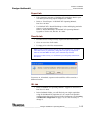
Note. Check all items mentioned below by and confirm them by ;.
Then, send back this form to your Thermo Electron Customer Support
Organization.
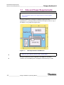
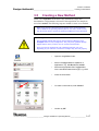
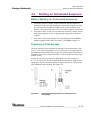
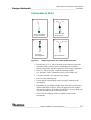
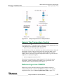
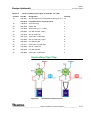
Finnigan GasBench II is attached to Finnigan isotope ratio mass
spectrometers, e.g. Finnigan DeltaplusXP, and will be placed either on top of
the IRMS or on a peripherals support table.
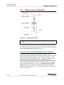
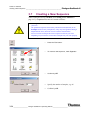
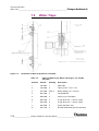
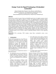
Figure 1-1.
1-2
Site Requirements of GasBench II
Note. The space required is 900 mm width * 900 mm depth.
Finnigan GasBench II will be supplied by the IRMS line distributor.
Therefore, the total IRMS power consumption will increase by 0.5 kW.
____________________ Finnigan GasBench II Operating Manual ____________________
Thermo
ELECTRON CORPORATION
Finnigan GasBench
Preinstallation Requirements
II _____________________________________________________ Gas Requirements
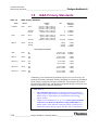
1.2
Gas Requirements
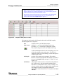
•
He 5.0 (that is 99.999 %)
4 bar as carrier gas
•
He 4.6 with 0.3 % CO2 4.5
4 bar for acceptance tests
For Water Equilibration
•
18
•
HD
O He 4.6 with 0.3 %-1 % CO2 4.5 4 bar as auxiliary gas
CO2 4.5 (that is 99.995 %)
4 bar as reference gas
He 4.6 with 2 % H2
H2 4.5 (that is 99.995 %)
4 bar as auxiliary gas
4 bar as reference gas
For Carbonates
•
CO2 4.5 (that is 99.995 %)
4 bar as reference gas
For DIC (Dissolved Inorganic Carbon)
•
Warning. All gas lines should be oil-free and preferably flame-dried. The
gas lines, or gas tanks respectively, should be at a distance of 1 - 1.5 m to the
instrument.
CO2 4.5 (that is 99.995 %)
4 bar as reference gas
Warning. All regulators should be oil- and fat-free and be specified for
gases of high purity.
The supply lines should terminate with 1/8 “ male Swagelok®-type
connectors.
Compressed air will be supplied by the compressed air distributor of the
IRMS and should be between 40 psi and 70 psi.
Note. Sometimes, it may be necessary to check the unit for leaks. Therefore,
use an argon tank.
Note. Thermo Electron (Bremen) recommends to install a high capacity
purifier (Part No. 114 0790) to ensure constant and affordable high quality
of the helium carrier gas.
Thermo ____________________ Finnigan GasBench II Operating Manual ___________________
ELECTRON CORPORATION
1-3
Chapter 2
Hardware Components
2.1 GasBench II Layout
2.2 Autosampler
2.3 Sample Trays
2.4 Gas Supply
2.5 Measurement Needle
2.6 Flush Needle
2.7 Mounting Syringe Needles into Autosampler
2.8 On-Line Water Removal
2.9 Principle of Valco Eight Port Valve
2.10 GC Oven
2.11 Open Splits
Thermo ____________________ Finnigan GasBench II Operating Manual ___________________
ELECTRON CORPORATION
2-1
Hardware Components
GasBench II Layout ________________________________________________
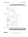
2.1
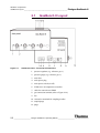
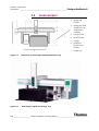
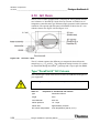
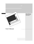
Figure 2-1.
Finnigan GasBench II
GasBench II Layout
GasBench II Unit - Front and Left Side View
1. pressure regulator (e.g. reference gas 1)
2. pressure gauge (e.g. reference gas 1)
3. main fuse
4. main power plug
5. main power switch (on/off)
6. JUMO itron 16 temperature controller
7. cable for connection to IRMS
8. gas connection terminal (refer to Figure 2-14).
9. fan
10. connection terminals for sampling needles
11. sample/purge
12. purge
2-2
____________________ Finnigan GasBench II Operating Manual ____________________
Thermo
ELECTRON CORPORATION
Finnigan GasBench
Hardware Components
II _____________________________________________________GasBench II Layout
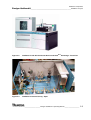
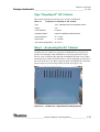
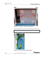
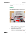
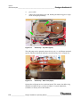
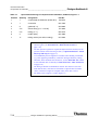
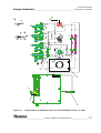
Figure 2-2.
GasBench II with Kiel Carbonate Device and DeltaPlus Advantage - Front View
Figure 2-3.
GasBench II General Survey - Open
Thermo ____________________ Finnigan GasBench II Operating Manual ___________________
ELECTRON CORPORATION
2-3
Hardware Components
Autosampler _____________________________________________________
2.2
Finnigan GasBench II
Autosampler
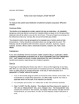
1. display and
controls
2. heating unit with
JUMO itron 16
temperature
controller
3. syringe carrier
4. injection head
5. syringe
6. position of
measurement
needles
7. sample tray
Figure 2-4.
Schematic of Autosampler A200S and Sample Tray
Figure 2-5.
Autosampler A200S and Sample Tray
2-4
____________________ Finnigan GasBench II Operating Manual ____________________
Thermo
ELECTRON CORPORATION
Finnigan GasBench
Hardware Components
II __________________________________________________________ Autosampler
Installing the Autosampler
Note. The x-axis is the long axis at the autosampler, whereas the y-axis is
directed forward, and the z-axis downwards, respectively.
1. Unpack the box containing the autosampler’s components.
2. Screw the autosampler’s feet onto the base plate.
Note. The base plate is not packed into the autosampler box, but into the box
containing GasBench II.
The feet, however, are packed into the autosampler box.
3. Place sample tray and heating block onto the base plate. Therefore, the
base plate has prefabricated cut-outs, where the heating block is simply
inserted. Due to its heaviness, the heating block must not be fixed by
screws underside.
4. Unpack the temperature controller for the heating block. The lid of the
heating block needs to be screwed sideways onto the heating block by two
provided kurled head screws.
Note. In case of carbonate option, a cut-out must be rasped at the right rear
edge of the lid. The cut-out will be used as feedthrough for the acid line of
the acid reservoir. Usually, this is performed by a service engineer.
5. Take out the z-arm.
6. Mount the x-axis-guidance upon the feet and fasten it there using a torx
screwdriver. Three torx screwdrivers are provided together with the
autosampler.
7. Unscrew the retaining screws out of the y-arm.
8. Attach the z-arm at the y-arm. To fasten the z-arm, move the plunger
entirely downward as this allows accessing the eyelets.
9. Remove the protective faceplate from the z-arm. This allows to plunge in
the syringe from the front side later on.
Note. When the autosampler is switched off (e.g. during installation here), in
most cases the plunger falls completely down and can then be moved freely.
However, the plunger cannot be moved when the autosampler is switched
on.
Torx Screwdrivers Provided with the Autosampler
•
360/T 10 * 80
Thermo ____________________ Finnigan GasBench II Operating Manual ___________________
ELECTRON CORPORATION
2-5
Hardware Components
Autosampler _____________________________________________________
•
360/T 20 * 100
•
360/T 25 * 100
Finnigan GasBench II
Connecting the Autosampler
Warning. Never unplug or connect any cables while the autosampler is
switched on! This may lead to damage of the autosampler.
Note for Service Engineer. Part No of replacement fuse is 114 1420.
1. Connect the serial cable of the autosampler to the serial port COM 1 of
your computer.
2. Mount the autosampler display on the most convenient side of the
autosampler. Connect the autosampler display to the rear panel of the
autosampler by the serial cable. See 8, that is serial 3, in Figure 2-6.
3. Connect the autosampler power supply to the mains supply and the
autosampler.
1. (Auxiliary 1) - Combi PAL
only
2. (Auxiliary 2) - Combi PAL
only
3. (Interface 1) - Combi PAL
only
4. (Interface 2) - Combi PAL
only
5. main power - connect to
autosampler power supply
6. LED
7. speaker (buzzer)
8. Ser 3 - to autosampler display
9. Ser 2
10. Ser 1 - to host computer
Figure 2-6.
2-6
Syringe Carrier Rear Panel (GC PAL or Combi PAL)
____________________ Finnigan GasBench II Operating Manual ____________________
Thermo
ELECTRON CORPORATION
Finnigan GasBench
Hardware Components
II _________________________________________________________ Sample Trays
2.3
Sample Trays
Layout
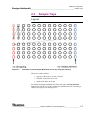
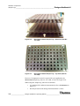
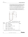
Figure 2-7.
Schematic of Autosampler Movement across the Trays (Ex Factory)
The trays contain 96 holes:
•
spacing of the holes is 26 mm * 26 mm
•
diameter of the holes is 16 mm
•
depth of the holes is 85 mm
Per default, Finnigan GasBench II is delivered with a non-thermostated
sample tray, Part No. 111 2780, suitable for equilibrium work or breath gas
analysis. See Figure 2-8 and Figure 2-9.
Thermo ____________________ Finnigan GasBench II Operating Manual ___________________
ELECTRON CORPORATION
2-7
Hardware Components
Sample Trays _____________________________________________________
Finnigan GasBench II
Figure 2-8.
Non-Thermostated Sample Tray - Side View (Part No.
111 2780)
Figure 2-9.
Non-Thermostated Sample Tray - Top View (Part No.
111 2780)
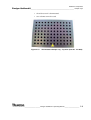
However, if temperature control is required for your application, the
thermostated sample tray, Part No. 111 2800, is used. See Figure 2-10.
When using this sample tray, take into account that:
2-8
•
it is optimized for carbonate measurement (refer to Carbonates on
page 5-6).
•
the delay between acid dosing and measurement is 1 hour.
____________________ Finnigan GasBench II Operating Manual ____________________
Thermo
ELECTRON CORPORATION
Finnigan GasBench
Hardware Components
II _________________________________________________________ Sample Trays
•
the acid reservoir is thermostated.
•
two columns can not be used.
Figure 2-10.
Thermostated Sample Tray - Top View (Part No. 111 2800)
Thermo ____________________ Finnigan GasBench II Operating Manual ___________________
ELECTRON CORPORATION
2-9
Hardware Components
Sample Trays _____________________________________________________
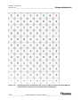
Figure 2-11.
Finnigan GasBench II
Sampling Positions as Defined in the “Tray 01” Object in the Autosampler Memory
and Crosslink to Sequence Lines within Sequence Examples
2-10 ___________________ Finnigan GasBench II Operating Manual ____________________
Thermo
ELECTRON CORPORATION
Finnigan GasBench
Hardware Components
II _________________________________________________________ Sample Trays
b
a autosampler position in sequence
a
c
b row number in sequence (carbonates)
c row number in sequence (equilibration)
d
d double needle flush
e flush fill
e
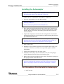
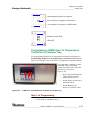
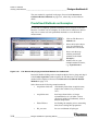
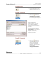
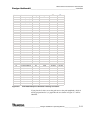
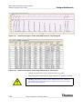
Programming JUMO itron 16 Temperature
Controller for Sample Tray
For programming JUMO itron 16 temperature controller for GC oven, see
Programming JUMO itron 16 Temperature Controller for GC Oven on
page 2-32. For details refer to Jumo itron 16 temperature controller manual.
The temperature controller, located
externally, allows controlling
sample tray temperature. Notice the
three keys (see arrows in
Figure 2-12):
•
P key (for programming; the
values will be accepted
automatically after 2 s).
•
Arrow Up key (to increase a
particular value)
•
Figure 2-12.
Arrow Down key (to
decrease a particular value)
JUMO itron 16 Temperature Controller for Sample Tray
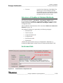
Step 1 of Programming
•
Press the P key and hold it for 2 s.
Thermo ____________________ Finnigan GasBench II Operating Manual __________________ 2-11
ELECTRON CORPORATION
Hardware Components
Sample Trays _____________________________________________________
Finnigan GasBench II
•
Pass through the menu until Y.0 is displayed.
•
Again, press the P key and hold it for 2 s.
Set C111 to 003 (transducer type, e.g. Pt 100, 2-wire).
Set C112 to 1 (number of decimal places and temperature unit, e.g. 1
and ºC).
Set C113 to 33 (controller type, e.g. double setpoint).
Set C115 to 1 (ramp function, that is, ramp function in ºC/min).
Set C116 to 0 (outputs on fault, that is 0 %; minimum output limiting
Y.2 is effective).
Set SP.L to 0 (lower setpoint limiting).
Set SP.H to 80 (upper setpoint limiting).
Set OFFS to 0 (process value correction).
Step 2 of Programming
•
Again, press the P key and hold it for 2 s.
•
Press the Arrow Up/Down key to change values.
Set Pb.1 to 2.8 (proportional band 1).
Set Pb.2 to 2.8 (proportional band 2).
Set d.t. to 35 (derivative time in s).
Set r.t. to 135 (reset time in s).
Set CY.1 to 2 (cycle time 1 in s).
Set CY.2 to 2 (cycle time 2 in s).
Set db to 0 (contact spacing).
Set HyS.1 to 0 (differential 1).
Set HyS.2 to 0 (differential 2).
Set Y.0 to 0 (working point in %).
Set Y.1 to 100 (maximum output in %).
Set Y.2 to 0 (minimum output in %).
Set d.F to 5 (filter time constant in s).
Set rA.Sd. to 9.99 (ramp slope in ºC/h or ºC/min).
Alternative: Automatic Programming
Let the temperature controller program itself automatically. Thereby, you
don’t need to specify all the parameters mentioned above on your own.
2-12 ___________________ Finnigan GasBench II Operating Manual ____________________
Thermo
ELECTRON CORPORATION
Finnigan GasBench
Hardware Components
II ___________________________________________________________ Gas Supply
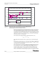
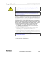
2.4
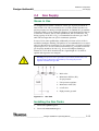
Gas Supply
Gases in Use
For all applications helium is needed as carrier gas. Its purity should be at
least 99.999 % He. We recommend to use a second cylinder switchover to
prevent pressure loss during overnight operation. A standard 50 l gas tank has
a lifetime of half a year in continuous operation. For all applications with CO2
as molecule of interest, that is water equilibration, DIC or carbonates, CO2
having a purity of 99.995 % CO2 is recommended as reference gas. A 40 l
tank will last longer than one year in continuous operation.
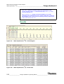
In case of CO2 water equilibration, additionally a mixture of CO2 in He is
needed for headspace flushing. The purities are recommended to be as stated
above for He and CO2 respectively. A CO2 content of 0.3 % leads to an ideal
signal height of 9 V. In case of H/D measurements, H2 is needed as reference
gas. Its purity should be 99.996 % H2. In case of headspace flushing, a
mixture of 2 % H2 in He should result in a signal height of 9 V, which is
optimal with regard to error margins.
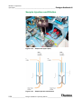
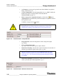
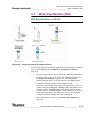
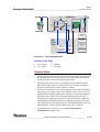
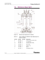
Warning. The pressure of new gas tanks is up to 200 bar (helium tank). The
pressure must be adjusted to approximately 4 bar using the pressure
regulator mounted at the gas tank.
1. Main valve
2. Manometer 200 bar (He),
for pre-pressure
3. Line pressure regulator
4. Manometer 4 bar (He)
5. on/off valve
6. High pressure gas tank
Figure 2-13.
Gas Tank
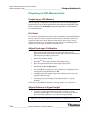
Installing the Gas Tanks
1. Connect the reference gases:
2. Connect the measurement gases.
Thermo ____________________ Finnigan GasBench II Operating Manual __________________ 2-13
ELECTRON CORPORATION
Hardware Components
Gas Supply ______________________________________________________
Finnigan GasBench II
3. Connect the equilibration gases, that is flush gases:
Either [CO2 + He] or [H2 + He] are used as equilibration gases
(0.5% CO2 in He because of 50 V dynamic range).
Working with the Gas Tanks
Warning. It is strongly recommended to install the gas tanks firmly.
Tumbling must definitely be prevented!
Warning. A leak in the hydrogen (H2) supply may cause fire or an
explosion!
Before starting the system, a leak check must be performed outside the
working area:
1. After mounting the reducing valve to the gas tank, both valves should be
open (that is, the on/off valve and the reducing valve, see Figure 2-13).
2. Open the main valve for two or three seconds to let the gas purge the
whole valve system (see Figure 2-13).
3. Close the on/off valve. Then close the main valve.
4. Mark the manometer positions of on/off valve and main valve and wait
for 10 - 15 min.
5. If the manometer positions have changed, a leak may be present.
6. To detect the leak brush all valves and connections carefully with soap
sud. A possible leak is indicated by gas bubbles.
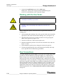
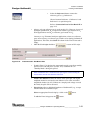
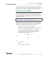
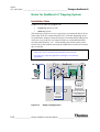
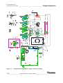
Gas Connections
To operate GasBench II and the IRMS, several gases are needed either from
gas tanks or from the laboratory’s main gas supply (e.g. compressed air).
Refer to Figure 2-14 to locate the following numbers. To operate the open
split levers, the valco valve and eventually the traps, compressed air of 4 bar
is required (40 - 70 psi; see also Pos. 5 in Figure 2-14). It can be provided by
the pressure regulator of the IRMS. Two capillaries leading the gas flow to the
mass spectrometer input valve must be installed (see Pos. 4 in Figure 2-14).
The connections 1 to 3 are used for the reference gases used in the various
applications. Flush gases must be connected to the respective connector (for
detailed explanation, refer to Measurement Procedures for Real Samples
on page 5-1.
2-14 ___________________ Finnigan GasBench II Operating Manual ____________________
Thermo
ELECTRON CORPORATION
Finnigan GasBench
Hardware Components
II ___________________________________________________________ Gas Supply
Warning. When installing CO2 reference gas tanks, keep in mind that
standard high pressure tanks for CO2 contain a liquid phase that is subject to
fractionation when temperature changes. These tanks must be stored at
constant temperature to obtain stable isotope values for your reference gas.
When using hydrogen (H2) as reference gas, it is necessary to shorten the
internal flow restricting capillary (that is, the capillary leading from the
reference pressure regulator to the open split, 3-fold) to approximately 50 %
of its original length. This ensures that enough hydrogen enters the mass
spectrometer’s reference port. Refer to Figure 7-8, Figure 7-9 and Table 7-8.
Use the quick release connection to connect the blue compressed air cable to
the compressed air connectors of the IRMS. See Figure 7-10. As the IRMS
has four connectors, four screws (wing unions for compressed air, quick
release connections) are provided either with GasBench II or with the IRMS
itself.
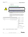
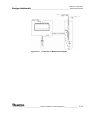
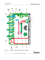
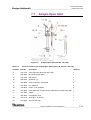
Figure 2-14.
1-3
connections for reference gases
4
capillary feedthrough to IRMS
5
connection for compressed air
6
He carrier gas connection
7
flush connection
8
GND (ground)
Connection Panel of Gas Bench II
It is intended to connect only one equilibration gas to the flush port. Ex
factory, the helium inlet port is connected to a t piece, which feeds the flush
port with helium. The service engineer will connect helium at the upper inlet
port and the reqired flush gas at the lower inlet port.
Thermo ____________________ Finnigan GasBench II Operating Manual __________________ 2-15
ELECTRON CORPORATION
Hardware Components
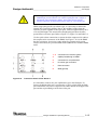
Measurement Needle _______________________________________________
2.5
Finnigan GasBench II
Measurement Needle
Figure 2-15.
Measurement Needle
Note. The measurement needle is sometimes synonymously called transfer
needle.
The measurement needle is located in the Combi Pal autosampler. The correct
connection is important to guarantee high GC performance. Refer to How to
Connect the Measurement Needle on page 2-16.
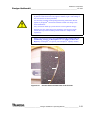
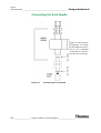
How to Connect the Measurement Needle
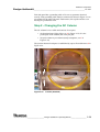
Connect the measurement needle as outlined in Figure 2-16. The
measurement needle should direct the He flow through the side hole and take
up the sample through the needle tip. This ensures dead volume free and,
therefore, memory free sampling. The CO2 + He carrying capillary and the
corresponding bulkhead connector should be marked by a flag, see
Figure 2-16. Now, helium gently moves CO2 from the exetainer’s headspace
into the fused silica capillary within the needle tip. From here, the sample is
transferred through the water removal (1, see Principle of On-Line Water
Removal on page 2-21) and the valco loop for GC injection. The He flow
should be at approximately 0.4 - 0.5 ml/min (measured at the vent of the valco
valve; see Figure 2-25).
2-16 ___________________ Finnigan GasBench II Operating Manual ____________________
Thermo
ELECTRON CORPORATION
Finnigan GasBench
Hardware Components
II ___________________________________________________ Measurement Needle
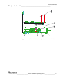
Figure 2-16.
Connection of Measurement Needle
Thermo ____________________ Finnigan GasBench II Operating Manual __________________ 2-17
ELECTRON CORPORATION
Hardware Components
Flush Needle _____________________________________________________
2.6
Finnigan GasBench II
Flush Needle
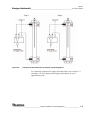
How to Connect the Flush Needle
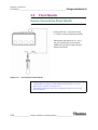
Figure 2-17.
•
Flushing with He (~ 100 ml/min during
4 - 6 min) in case of carbonates and DIC
•
Filling with a gas mixture of 0.3 - 0.4 %
CO2 in He and a flow of of 50 ml/min
makes the use of glove bags and glove
boxes unnecessary.
Connection of Flush Needle
Note. It is possible to connect two flush needles and operate them
simultaneously by using our double needle holder (Part No. 113 7120).
Refer to Pos. 2 and Pos. 4 in Figure 2-18.
The double needle holder is part of the Carbonate Kit (Part No. 064 4520).
Refer to Table 6-1.
2-18 ___________________ Finnigan GasBench II Operating Manual ____________________
Thermo
ELECTRON CORPORATION
Finnigan GasBench
Hardware Components
II _________________________________ Mounting Syringe Needles into Autosampler
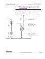
2.7
Mounting Syringe Needles into
Autosampler
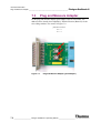
Figure 2-18 outlines the mounting of needles into the autosampler’s needle
holder. Notice that the relative positions between two needles are fixed when
inserted into the holder. See Carbonate Option (Part No. 113 2471) Components on page 6-2 for the part numbers.
Figure 2-18.
1
any needle from flushing,
measuring or acid
2
supporting screw
Refer to needle holder,
Part No. 113 7080.
3
nut
4
single needle holder or
double needle holder
(complete, Part No. 113 7120)
Mounting Sampling or Flush Needles into Needle Holder
Thermo ____________________ Finnigan GasBench II Operating Manual __________________ 2-19
ELECTRON CORPORATION
Hardware Components
Mounting Syringe Needles into Autosampler
______________________________ Finnigan GasBench II
Figure 2-19.
Double Needle Holder (Dismantled, left and within the Autosampler, right)
Figure 2-20.
Inserting Double Needle Holder into Autosampler
2-20 ___________________ Finnigan GasBench II Operating Manual ____________________
Thermo
ELECTRON CORPORATION
Finnigan GasBench
Hardware Components
II _________________________________________________ On-Line Water Removal
2.8
On-Line Water Removal
GasBench II is equipped with two on-line water removals. One of them is
positioned in front of the Valco eight port valve, whereas the other one is used
as a guard trap in front of the open split interface to the IRMS.
See Figure 2-21.
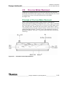
Principle of On-Line Water Removal
Water is removed from the transfer sample stream by a gastight but
hygroscopic Nafion® tubing. The sample flow (He + CO2 + H2O, 0.5 ml/min)
passes through the Nafion® tubing which is mounted co-axially inside a glass
tube. This glass tube, and therefore the outer surface of the Nafion® tube, is
constantly kept dry by a He flow of approximately 8 ml/min. Due to the water
gradient through the Nafion® wall any water in the sample flow will move
through the Nafion®. A dry (He + CO2) gas results which flows towards the
Valco loop.
Figure 2-21.
Schematic Online Water Removal
Thermo ____________________ Finnigan GasBench II Operating Manual __________________ 2-21
ELECTRON CORPORATION
Hardware Components
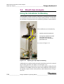
Principle of Valco Eight Port Valve ______________________________________
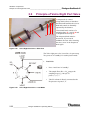
2.9
Finnigan GasBench II
Principle of Valco Eight Port Valve
1 compressed air control
2 long shank; allows to introduce
the functional head into the oven as
head and control are thermally
separated by the distance.
3a 3b 3c
The chequered knob must be
unscrewed, if you want to
withdraw the rotor. After inserting
the rotor, screw in the chequered
knob again.
2
1
Figure 2-22.
3 functional head; consists of a
mounting plate 3a, a n-port 3b and
a chequered knob on top 3c.
Valco Eight Port Valve - Side View
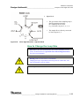
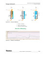
The Valco eight port valve is used in a six port setup.
Two ports are in "standby" for each injection mode.
1. Load Mode
Figure 2-23.
•
Ports 1 and 8 are in "standby".
•
The sample flow (He + CO2) purges the
sampling loop (e.g. 100 Pl) via
ports 2 ¦ 3 ¦ 6 ¦ 7.
•
The GC column is directly connected to the
He pressure via ports 5 ¦ 4.
Valco Eight Port Valve - Load Mode
2-22 ___________________ Finnigan GasBench II Operating Manual ____________________
Thermo
ELECTRON CORPORATION
Finnigan GasBench
Hardware Components
II _________________________________________ Principle of Valco Eight Port Valve
2. Inject Mode
Figure 2-24.
•
The gas content of the sampling loop is
directly transferred onto the
GC column by the GC flow
(e.g. 2 ml/min) via ports 5 ¦ 6 ¦ 3 ¦ 4.
•
The sample flow is directly connected
to Vent via ports 2 ¦ 1.
Valco Eight Port Valve - Injection Mode
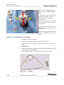
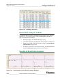
How to Change the Loop Size
Note. Refer to the valco documentation, that is Valco Instruments Co. Inc.
(VICI): Technical Note 201: Operation Notes and Cleaning Instructions.
It is part of your equipment.
Warning. Make sure the Valco is in Load Mode!
Changing the loop in Inject Mode will interrupt the GC column flow. This
will cause damage to the GC column.
Warning. Always use Valco stainless steel ferrules for mounting the loop.
Thermo ____________________ Finnigan GasBench II Operating Manual __________________ 2-23
ELECTRON CORPORATION
Hardware Components
Principle of Valco Eight Port Valve ______________________________________
Finnigan GasBench II
The arrows in Figure 2-25 show
the two screws, which fasten the
loop.
2
1 chequered screw; is used to fix the
internal rotor, which is flexibly
fitted within in the stator by a
conical seal.
2 socket head screw; is used after
fixing the internal rotor by the chequered screw.
1
The socket head screw allows to adjust the pressure acting from above
upon the cone.
1 mm loop
Figure 2-25.
By increasing this pressure the internal rotor is tighted against the side
walls.
Valco Valve with Loop - Top View
1. Switch the Valco to Load Mode.
2. Open the nuts on Port 3 and Port 6. Refer to Figure 2-25.
3. Replace the loop.Use loop sizes less than 250 ml for the two column
types.
4. Tighten the nuts.
5. Inject the measurement needle into a helium-filled vial and purge the loop
before switching to Inject Mode.
6. At the Valco vent (Port 7) check for a purge flow of 0.3 - 0.5 ml.
Figure 2-26.
1 ml Loop
2-24 ___________________ Finnigan GasBench II Operating Manual ____________________
Thermo
ELECTRON CORPORATION
Finnigan GasBench
Hardware Components
II _________________________________________ Principle of Valco Eight Port Valve
Figure 2-27.
2 ml Loop
Figure 2-26 and Figure 2-27 are shown above as examples. Loops of 100 µl,
250 µl and 1 ml are already part of your equipment provided by Thermo
Electron (Bremen). If necessary, loops of even bigger volumes are available.
The 1 ml loop and the 100 Pl loop are very similar.
Thermo ____________________ Finnigan GasBench II Operating Manual __________________ 2-25
ELECTRON CORPORATION
Hardware Components
GC Oven ________________________________________________________
Finnigan GasBench II
2.10 GC Oven
The GC oven is either equipped with a "HayeSep D" micro-packed stainless
steel column or a "PoraPlot Q" fused silica cap column. A JUMO itron 16
temperature controller and a type K thermocouple guarantee stable isothermal
conditions. The opened right side panel of GasBench II shows the GC oven
with the column. See Figure 2-28 and Figure 2-32.
Figure 2-28.
GC Oven - Open
The GC column separates the different gas compounds released from the
sample loop, e.g. N2 and CO2. The compounds eluting from the GC column
are transferred through the Nafion® guard trap and via open split into IRMS.
Type "PoraPlot Q" GC Column
This column type is used in the current versions of GasBench II and part of
your equipment.
Warning. Avoid fast pressure variations along the column (' p < 0.5 psi/s)!
Table 2-1.
Properties of “PoraPlot Q“ GC Column
type
fused silica column
length
25 m
inner diameter
0.32 mm
helium pressure
10 - 12 psi
helium flow
approximately 2 ml/min
GC column temperature
room temperature (that is, 24 °C)
2-26 ___________________ Finnigan GasBench II Operating Manual ____________________
Thermo
ELECTRON CORPORATION
Finnigan GasBench
Hardware Components
II _____________________________________________________________ GC Oven
Type "HayeSep D" GC Column
This column type has been used in prior versions of GasBench.
Table 2-2.
Properties of “HayeSep D“ GC Column
type
1/16´´ stainless steel micro packed column
length
2m
inner diameter
0.76 mm
packing material
polymer HayeSep D; 80/100 mesh
helium pressure
10 - 15 psi
helium flow
3 - 4 ml/min
GC column temperature
50 - 60 °C
Step 1 - Accessing the GC Column
Currently, the GC column is a static part of GasBench II as it nearly never
needs to be exchanged. Only maintenance is necessary from time to time.
The GC oven is located at the right side of GasBench II (front view). When
inserting the GC column for the first time or when exchanging it, first remove
the cover of the GC oven (that is right side panel of GasBench II). Therefore,
unscrew all seven screws using an allen wrench. See Figure 2-29.
Figure 2-29.
GasBench II - Right Side Panel Being Opened
Thermo ____________________ Finnigan GasBench II Operating Manual __________________ 2-27
ELECTRON CORPORATION
Hardware Components
GC Oven ________________________________________________________
Figure 2-30.
Finnigan GasBench II
GasBench II - Right Side Panel Removed
Afterwards, only remove the two screws marked by arrows in Figure 2-30.
Note. Leave the remaining four screws that are marked by white circles
untouched, as they hold the isolation of the GC oven!
Figure 2-31.
Grounding Cable of Right Side Panel
2-28 ___________________ Finnigan GasBench II Operating Manual ____________________
Thermo
ELECTRON CORPORATION
Finnigan GasBench
Hardware Components
II _____________________________________________________________ GC Oven
Each side panel has a grounding cable of its own to guarantee electrical
security. Each grounding cable must be connected as shown in Figure 2-31 as
an example for the right side panel. Furthermore, the top side and the oven
housing are grounded as well.
Step 2 - Changing the GC Column
The GC column is now visible and consists of two parts:
•
the functional part (light yellow, see 3 in Figure 2-34). It is the
packed part of the column, that is the plot part.
•
the post-column or pre-column (nearly transparent; see 1 in
Figure 2-34)
The junction between both parts is established by a press-fit and shown as 2 in
Figure 2-34.
1
2
Figure 2-32.
Column (Installed)
Thermo ____________________ Finnigan GasBench II Operating Manual __________________ 2-29
ELECTRON CORPORATION
Hardware Components
GC Oven ________________________________________________________
Figure 2-33.
Finnigan GasBench II
Column (with Blocked Ends)
Figure 2-33 shows the ends of the column, which are blocked by silicon
plugs.
•
Cut the silicon plugs off using a capillary cutter.
•
Thereafter, insert each end into its bulkhead connection at the left side of
the oven (see 1 and 2 in Figure 2-32) as follows:
•
•
The bulkhead connection, which is connected to the valco, is intended
for the inlet of the column. It must be connected to the functional part
of the column (light yellow).
•
As the outlet, the post-column must be connected to the bulkhead
connection that is directed towards the water trap. The water trap, in
turn, leads to the diluter, that is to the open active split. The
post-column (nearly transparent) acts as a particle trap, that is it
prevents particles from reaching rear valves.
Screw the Swagelok® connection or valco connection on as follows:
•
Insert the respective ferrule.
•
Newly cut the capillary off.
•
Introduce the capillary.
•
Carefully tighten the ferrule until the capillary can no longer be
pulled back. Do not tighten the ferrules/connections too strong!
2-30 ___________________ Finnigan GasBench II Operating Manual ____________________
Thermo
ELECTRON CORPORATION
Finnigan GasBench
Hardware Components
II _____________________________________________________________ GC Oven
Warning. If you want to tighten the ferrule further, it is absolutely necessary
to perform a leak check first! Only tighten it further, if gas is still coming in
after the leak test has been performed.
Act extremely carefully while opening and closing connections! Do not
tighten any Swagelok® connection around the column too strong as this
causes demolition!
Only connections made up by metal ferrules can be tightened strongly.
Normally, the only connections to be touched by users are those of the
column, the loop and for installing a flush needle or a sample needle,
respectively.
Note. For detailed information about Installation of the column in the GC,
Conditioning, Storage and Description refer to Capillary Column Test
Report by Chrompack®. It is part of your Chrompack® capillary column.
1
2
3
Figure 2-34.
Junction between Both Parts of the Column
Thermo ____________________ Finnigan GasBench II Operating Manual __________________ 2-31
ELECTRON CORPORATION
Hardware Components
GC Oven ________________________________________________________
Finnigan GasBench II
Programming JUMO itron 16 Temperature
Controller for GC Oven
Figure 2-35.
Jumo itron 16 Temperature Controller
The temperature controller, located at the side panel of GasBench II, allows to
control the temperature of the GC oven. Notice the three keys:
•
P key
(for programming; values will be accepted automatically after 2 s).
•
Arrow Up key
(for increasing a particular value)
•
Arrow Down key
(for decreasing a particular value)
Programming - Step 1
•
Press the P key and hold it for 2 s.
•
Pass through the menu until Y.0 is displayed.
•
Again, press the P key and hold it for 2 s.
Set C111 to 043 (transducer type, e.g. NiCr-Ni, K).
Set C112 to 1 (number of decimal places and temperature unit, e.g. 1
and ºC).
Set C113 to 33 (controller type, e.g. double setpoint).
Set C115 to 0 (ramp function, that is ramp function off).
2-32 ___________________ Finnigan GasBench II Operating Manual ____________________
Thermo
ELECTRON CORPORATION
Finnigan GasBench
Hardware Components
II _____________________________________________________________ GC Oven
Set C116 to 0 (outputs on fault, that is 0 %; minimum output limiting
Y.2 is effective).
Set SP.L to 0 (lower setpoint limiting).
Set SP.H to 200 (upper setpoint limiting).
Set OFFS to 0 (process value correction).
For details refer to Jumo itron 16 temperature controller manual.
Programming - Step 2
•
Again, press the P key and hold it for 2 s.
•
Press the Arrow Up/Down key to change values.
Set Pb.1 to 9.1 (proportional band 1).
Set Pb.2 to 0.9 (proportional band 2).
Set d.t. to 61 (derivative time in s).
Set r.t. to 243 (reset time in s).
Set CY.1 to 50.4 (cycle time 1 in s).
Set CY.2 to 50.4 (cycle time 2 in s).
Set db to 0 (contact spacing).
Set HyS.1 to 0 (differential 1).
Set HyS.2 to 0 (differential 2).
Set Y.0 to 0 (working point in %).
Set Y.1 to 100 (maximum output in %).
Set Y.2 to 0 (minimum output in %).
Set d.F to 6.5 (filter time constant in s).
Set rA.Sd. to 0 (ramp slope in ºC/h or ºC/min).
For details refer to Jumo itron 16 temperature controller manual.
Alternative - Automatic Programming
Let the temperature controller program itself automatically. Thereby, you
don’t need to specify all the parameters mentioned above on your own. For
details refer to Jumo itron 16 temperature controller manual.
Thermo ____________________ Finnigan GasBench II Operating Manual __________________ 2-33
ELECTRON CORPORATION
Hardware Components
Open Splits ______________________________________________________
Finnigan GasBench II
2.11 Open Splits
Reference Injection
This chapter outlines the functioning of the reference section of GasBench II.
Three reference gases can be injected via a three port open split interface. A
He stream of 2 ml/min permanently flushes the interface tube (see also
Figure 2-36 and Figure 2-37). A permanent flow of 0.25 ml/min transports the
content of the interface tube to the IRMS.
Figure 2-36.
Reference Inlet (Open Split)
2-34 ___________________ Finnigan GasBench II Operating Manual ____________________
Thermo
ELECTRON CORPORATION
Finnigan GasBench
Figure 2-37.
Hardware Components
II ___________________________________________________________ Open Splits
Principle of Reference Gas Introduction
Principle of Reference Gas introduction
•
left side:
reference gas on
•
right side:
reference gas off
To inject a reference gas, the corresponding reference capillary moves to the
bottom of the open split interface (see Figure 2-37). The reference gas,
e.g. CO2, is then mixed with the 4 ml/min He flow. Now, 0.25 ml/min of this
(He + CO2) mixture is transferred to the IRMS resulting in a rectangular
shaped reference gas pulse. The width of this pulse, e.g. 20 s, is defined by the
time between injecting and removing the reference gas capillary.
Thermo ____________________ Finnigan GasBench II Operating Manual __________________ 2-35
ELECTRON CORPORATION
Hardware Components
Open Splits ______________________________________________________
Finnigan GasBench II
Sample Injection and Dilution
Figure 2-38.
Sample Inlet (Open Split)
Figure 2-39.
Sample Injection and Dilution
2-36 ___________________ Finnigan GasBench II Operating Manual ____________________
Thermo
ELECTRON CORPORATION
Finnigan GasBench
Hardware Components
II ___________________________________________________________ Open Splits
Principle of Active Open Split
•
left side:
no dilution
•
right side:
dilution active
The transfer of the sample stream into the IRMS is achieved via the open split.
The capillary that leaves the second water trap enters the open split interface
as well as the retractable sampling capillary of the IRMS. A third capillary
(protection capillary) delivers a constant stream of dry helium, which purges
the exit volume of the open split at any time.
"OUT" position
•
The gas from the protection capillary mixes with the sample flow.
•
The IRMS capillary "sniffs" the diluted sample stream.
"IN" position
•
The IRMS capillary is moved to the bottom of the open split.
•
The IRMS capillary "sniffs" the sample stream eluted by the capillary
that comes from the second water trap.
Note. Notice a difference between GC applications and GasBench
applications:
In case of GC applications, the mass spectrometer capillary is completely
decoupled from GC.
In case of GasBench applications however, only partial decoupling occurs.
Thermo ____________________ Finnigan GasBench II Operating Manual __________________ 2-37
ELECTRON CORPORATION
Hardware Components
Open Splits ______________________________________________________
Finnigan GasBench II
2-38 ___________________ Finnigan GasBench II Operating Manual ____________________
Thermo
ELECTRON CORPORATION
Chapter 3
Isodat 2.0 Software
3.1 Starting Isodat 2.0
3.2 Creating a GasBench Configuration
3.3 Acquisition Mode
3.4 Accessories Bar
3.5 Creating a New Method
3.6 Different GasBench II Methods
3.7 Creating a New Sequence
3.8 Excel Export
3.9 Autosampler Programming
Thermo ____________________ Finnigan GasBench II Operating Manual ___________________
ELECTRON CORPORATION
3-1
Isodat 2.0 Software
Starting Isodat 2.0 _________________________________________________
3.1
Finnigan GasBench II
Starting Isodat 2.0
•
After installing Isodat 2.0, start it by
a double-click.
•
Open the Configurator by a double-click.
The Configurator window will appear.
•
This box only appears when starting the system
the very first time or after Reset of the IRMS.
•
Select your particular IRMS, e.g. Deltaplus XP
•
Confirm by OK.
•
3-2
Look, whether the cups are
Installed or Not Installed
.
•
Look at the Peak Center option
of the cups
.
•
Look at the Resistor values [:]
of the cups
.
•
Look at the Resistor 2 values [:]
of the cups
.
____________________ Finnigan GasBench II Operating Manual ____________________
Thermo
ELECTRON CORPORATION
Finnigan GasBench
Isodat 2.0 Software
II ______________________________________________________ Starting Isodat 2.0
Refer to the delivered test protocol and compare it with your order.
•
In the Gas Configuration Editor, check for your particular Configuration
(e.g. CO2) whether the masses are assigned correctly to the cups.
•
Check Calibration, Ratio Groups, magnet position and Peak Center
Offset. The default values for magnet position are averaged experience
values that cannot be checked and edited here, but later on during
calibration procedure.
•
The number of required cups (e.g. 3) is displayed together with the
corresponding masses (e.g. m/z 44, m/z 45, m/z 46) below the grid.
•
Finally, press the Save & Close button
•
The Configurator window will then appear.
.
Thermo ____________________ Finnigan GasBench II Operating Manual ___________________
ELECTRON CORPORATION
3-3
Isodat 2.0 Software
Creating a GasBench Configuration _____________________________________
3.2
Figure 3-1.
3-4
Finnigan GasBench II
Creating a GasBench
Configuration
Configurator Window
•
Isodat 2.0 automatically creates a new Configuration, named
My Configuration by default.
•
To give it a significant name, right-click on it and choose Rename.
•
Type a significant name, e.g. GasBench & A200S Sampler.
•
Expand the tree of the new Configuration by clicking the
____________________ Finnigan GasBench II Operating Manual ____________________
signs.
Thermo
ELECTRON CORPORATION
Finnigan GasBench
Isodat 2.0 Software
II ________________________________________ Creating a GasBench Configuration
•
Press the GasBench Sets tab
.
The different GasBench Sets are shown in the right pane as shown below:
•
Your selection should look similar to this example. Mark your particular
GasBench Set on the right pane, e.g. GasBench + A200S Sampler. For
details refer to Different GasBench II Methods on page 3-31.
•
Drag and drop it to Capillary port in the left pane.
Figure 3-2.
•
Select or deselect optional
hardware (that is
Flush Fill, Trap or Trap 2.
•
Confirm by OK.
Optional Hardware - Flush Fill, Trap and Trap 2
Thermo ____________________ Finnigan GasBench II Operating Manual ___________________
ELECTRON CORPORATION
3-5
Isodat 2.0 Software
Creating a GasBench Configuration _____________________________________
Finnigan GasBench II
Contrary to former times, Finnigan GasBench II now always contains a Flush
Fill. Finnigan GasBench II can be used either without a trap or with one trap
or with two traps. Traps are optional and provide additional opportunities.
Note. In Isodat versions older than Isodat 2.0, occasionally software
problems due to old scripts (that is .sct) occurred when no trap was installed.
In Isodat 2.0 however, new scripts (that is .isl) are used eliminating this
problem.
3-6
•
GasBench II and A200S
autosampler have been
attached to Capillary port.
•
Close the Configurator.
All settings will be saved
automatically.
____________________ Finnigan GasBench II Operating Manual ____________________
Thermo
ELECTRON CORPORATION
Finnigan GasBench
Isodat 2.0 Software
II _______________________________________________________Acquisition Mode
3.3
Acquisition Mode
This section outlines Acquisition Mode. For detailed information, refer to:
•
ISODAT NT Operating Manual, Part No. 109 2481
•
ISODAT NT Operating Manual - Upgrade to Version 2.0,
Part No. 115 49 90
•
Start Isodat 2.0 by a double-click.
•
Start Acquisition Mode.
You are now able to run any “Continuous Flow“
application which gives you full control over the
automated measurement.
Note. It is recommended to check first, whether the following toolbars (that
is dialog bars) are activated. Proceed as follows.
The Acquisition window appears.
•
Right-click on the title bar in its upper left
corner.
•
Select Properties.
Thermo ____________________ Finnigan GasBench II Operating Manual ___________________
ELECTRON CORPORATION
3-7
Isodat 2.0 Software
Acquisition Mode __________________________________________________
Finnigan GasBench II
•
Click on the Bars tab.
•
Mark the checkboxes of the bars you
want to be displayed.
•
Finally, confirm by OK.
The bars will appear in the
Acquisition Mode window.
Figure 3-3.
Properties Box
It is important to mark primarily the following bars:
•
Status Bar
•
Basic Bar
•
Accessories Bar
The individual bars mentioned in the box above are described in detail in the
ISODAT NT Operating Manual (Part No. 109 2481).
3-8
____________________ Finnigan GasBench II Operating Manual ____________________
Thermo
ELECTRON CORPORATION
Finnigan GasBench
Isodat 2.0 Software
II _______________________________________________________ Accessories Bar
3.4
Accessories Bar
•
To display the Accessories bar mark the corresponding checkbox in
Figure 3-3 and confirm by OK.
•
It is important that you have already created a Configuration that contains
GasBench II (e.g. GasBench II & A200S Sampler, refer to Creating a
GasBench Configuration on page 3-4).
•
Select this Configuration at the Status Bar as shown below
(see also bottom of Figure 3-4).
As defined in the Configurator, the selected configuration GasBench II &
A200S will appear together its configured features.
Troubleshooting - Error Messages
If an error message appears at the Status bar, check whether the configuration
has been set up correctly. The most common error messages are:
•
Plug & Measure devices could not been found.
It typically appears when the GasBench II connector has not been
plugged into the IRMS.
•
A configuration containing the acid pump has been selected although
the acid pump is not in use.
If you want to use this configuration anyhow, you must calibrate the
acid pump. This is possible only in Fake Mode.
After this calibration, a configuration containing the acid pump can
even be used for equilibration measurements.
Thermo ____________________ Finnigan GasBench II Operating Manual ___________________
ELECTRON CORPORATION
3-9
Isodat 2.0 Software
Accessories Bar ___________________________________________________
•
Finnigan GasBench II
The Accessories bar contains information about the:
IRMS*
MS State*
Focus Delta*
GasBench window*
See The GasBench Window on page 3-11.
File Browser*
•
Figure 3-4.
The Status Bar displays the actual Configuration
(e.g. GasBench II & A200S) and the actual
Gas Configuration, e.g. CO2.*
The Accessories Bar Together with the Status Bar
*For detailed information about the components of the Accessories bar, refer
to ISODAT NT Operating Manual, Part No. 109 2481.
3-10 ___________________ Finnigan GasBench II Operating Manual ____________________
Thermo
ELECTRON CORPORATION
Finnigan GasBench
Isodat 2.0 Software
II _______________________________________________________ Accessories Bar
Changing Visibility of its Components
Change visibility of individual components of the Accessories bar as follows:
•
Right-click on an arbitrary title bar
(e.g. GasBench or Focus Delta).
•
Mark the Administrate Panels button.
•
Mark the information to be displayed
(additionally) on the Accessories bar,
e.g. Focus Delta.
•
Unmark the information not to be displayed on
the Accessories bar, e.g. ISL Scripts.
•
Finally, confirm by OK.
The GasBench Window
The GasBench window (Figure 3-5) appears with any configuration containing
a GasBench, no matter whether an autosampler or an acid pump or a PreCon
device are additionally attached to it.
The GasBench window allows direct
control of all GasBench II hardware
components. Set or reset hardware components at any time, even during an acquisition.
Figure 3-5.
The GasBench Window
Thermo ____________________ Finnigan GasBench II Operating Manual __________________ 3-11
ELECTRON CORPORATION
Isodat 2.0 Software
Accessories Bar ___________________________________________________
Finnigan GasBench II
Click on a graphical object to operate the specific devices as there are:
•
flush fill valve
•
valco valve
•
open split
•
reference ports or traps
The Acid Pump Window
Note. If GasBench II is used with an acid pump, the corresponding
configuration containing the acid pump must be selected in the configurator
first. Beneath the GasBench window, the Acid Pump window will appear
(Figure 3-6).
Figure 3-6.
The Acid Pump Window
•
The number of acid drops per stroke needs first to be adjusted at the
acid pump itself (see Acid Pump Adjustment on page 6-5).
•
Then, this number must be communicated to Isodat 2.0.
Therefore, right-click somewhere into the Acid Pump window.
Click on the appearing
•
button.
Type in the number of acid drops per stroke adjusted at the acid pump
(default is 10) and confirm by OK.
3-12 ___________________ Finnigan GasBench II Operating Manual ____________________
Thermo
ELECTRON CORPORATION
Finnigan GasBench
Isodat 2.0 Software
II _______________________________________________________ Accessories Bar
Figure 3-7.
The Stroke Button
When you press the Stroke button, a single stroke of the acid pump will be
carried out. The Stroke button, usually grey, changes its color to green for the
duration of the stroke and returns to grey afterwards.
Figure 3-8.
Positions of the Direction Button
You can switch between the positions Fore and Back by pressing Direction
button. Both buttons are used to directly control the acid pump. When you try
them for the first time, check via Direction button, whether the acid pump
rotates forward by switching to Fore.
Stroke button controls rotation of the acid pump. A specific number of
rotations is needed to produce one drop of acid. This number must be
determined by the user and then saved in the Isodat 2.0 database using the
Calibrate button. It appears after right-click on the acid pump window.
The File Browser
Figure 3-9.
File Browser
Thermo ____________________ Finnigan GasBench II Operating Manual __________________ 3-13
ELECTRON CORPORATION
Isodat 2.0 Software
Accessories Bar ___________________________________________________
Finnigan GasBench II
The File Browser, also called File Browser bar, comprises six tabs:
Methods tab
Refer to Creating a New Method on page 3-17.
•
Methods provide the complete description of a single measurement.
•
Methods can be programmed or changed by the user.
•
Different methods have been predefined in the Examples folder of
the Methods tab. They cover all basic measurements.
Warning. Take them only as a guideline, but do not use them for
measurements! For measurements, always create your own methods!
Sequences tab
Refer to Creating a New Sequence on page 3-34.
•
Sequences contain the description of a sequence of single
measurements (methods).
•
Sequences can be programmed or changed by the user.
•
Different sequences have been predefined covering all basic
measurements (in the Examples folder of the Sequences tab).
Warning. Take them only as a guideline, but do not use them for
measurements! For measurements, always create your own sequences!
Warning. You must create and save a new method and a new sequence on
your own!
The predefined methods and sequences delivered by Thermo Electron
(Bremen) in the Examples folders are only example files. They only show
guidance through helpful default values, but must never be used for
measurements!
Never overwrite an example file with a method or sequence created on your
own! Depending on your software version these examples may not work
properly.
3-14 ___________________ Finnigan GasBench II Operating Manual ____________________
Thermo
ELECTRON CORPORATION
Finnigan GasBench
Isodat 2.0 Software
II _______________________________________________________ Accessories Bar
Export tab
•
Edit voluminous amounts of GasBench II acquisition data for your
own data systems using export templates (cf. LIMS).
•
Refer to “Excel Export“ in ISODAT NT Operating Manual;
Part No. 109 2481.
•
Use ISODAT NT’s Result Workshop to select and display particular
aspects of your acquisition data.
Refer to “Result Workshop“ in ISODAT NT Operating Manual Upgrade to Version 2.0; Part No. 115 4990.
Results tab
•
Provides access to all previously acquired measurement results.
•
Gives an overview of all results.
•
Is empty prior to the first measurement.
Note. To easily transfer and store data at your place of choice (e.g. on a drive
where data security is guaranteed), change the result path by a right-click
and then select Set Path. The basic path is automatically installed.
For reasons of data security, we recommend you to frequently benefit from
this feature.
From now on, all method, sequence and result files will be stored at a
different location.
ISL tab
•
Refer to ISODAT NT Operating Manual - Upgrade to Version 2.0;
Part No. 115 4990.
•
In the GasBench folder, you will find only one single acquisition
script for GasBench II (acquisition.isl). It is used for all possible
configurations that can be selected in the Configurator (see Creating
a GasBench Configuration on page 3-4). It is not necessary to
change it.
Thermo ____________________ Finnigan GasBench II Operating Manual __________________ 3-15
ELECTRON CORPORATION
Isodat 2.0 Software
Accessories Bar ___________________________________________________
Finnigan GasBench II
Note. All acquisition scripts are usually named acquisition.isl, no matter to
which application they belong (e.g. GasBench II or ConFlo III). However,
they are stored in separate folders (that is in a GasBench II folder or in a
ConFlo III folder).
Search tab
•
Allows to find any result files of data acquisitions by pressing the
File Search button.
•
Like a file manager, it displays the results of a file search and allows
to move files.
Browser tab
•
If a Result Workshop document is open, this tab shows the objects
that can be imported (e.g. methods, sequences, results).
•
A file manager that allows to browse to an arbitrary directory of your
choice, even to a root of a harddisk drive.
•
As with other file managers, files and folders can be created, moved
or deleted.
3-16 ___________________ Finnigan GasBench II Operating Manual ____________________
Thermo
ELECTRON CORPORATION
Finnigan GasBench
Isodat 2.0 Software
II _________________________________________________ Creating a New Method
3.5
Creating a New Method
Isodat 2.0’s Acquisition mode allows fully automated isotope ratio
determination. All parameters relevant for data acquisition of a sample are
stored in a method. The following steps are needed to create a new method.
Note. For an extensive description of the options of the method definition
refer to ISODAT NT Operating Manual (Part No. 109 2481). In this section,
only the entries that are specific for operating GasBench II will be described.
Warning. You must create and save a new method on your own!
The predefined methods delivered by Thermo Electron (Bremen) in the
Examples folder are only example files. They only show guidance through
helpful default values, but must never be used for measurements!
Never overwrite an example file with a method created on your own!
Depending on your software version these examples may not work properly.
•
Open the Acquisition mode.
•
Select a Configuration for GasBench II
applications, e.g. GasBench II & A200S.
•
Select the appropriate Gas Configuration
for the intended measurement type, e.g. CO2.
•
Press the New button.
•
To create a new method, mark Method.
•
Confirm by OK.
Thermo ____________________ Finnigan GasBench II Operating Manual __________________ 3-17
ELECTRON CORPORATION
Isodat 2.0 Software
Creating a New Method
_____________________________________________ Finnigan GasBench II
The new method is organized in tab pages. Proceed with Structure of
GasBench Related Methods on page 3-19, where they are described in
detail.
Predefined Methods as Examples
For the sake of simplicity, predefined methods can be selected via the File
Browser. Use them only as examples! It would even be sufficient to deliver
only one or at most two such predefined methods to cover all kinds of
measurements.
•
Click on File Browser’s
Methods tab
•
Select the location where
your own GasBench II
methods are to be stored.
Do not mix them up
with the predefined
methods in the folder
Examples!
•
Figure 3-10.
Double-click on your
example method of choice,
e.g. Acquisition.met.
File Browser Displaying Predefined Methods for GasBench II
Instead of double-clicking on the example method of choice, drag and drop it
to the Isodat Acquisition window right to the File Browser. The example
method will be displayed. Proceed with Structure of GasBench Related
Methods on page 3-19.
Select between the following example methods:
•
Acquisition 630s.met
considerably faster than Acquisition.met;
requires the column to be pre-heated to
70 ºC.
•
Acquisition.met
lasts longer than 1400 s; no longer
recommended, as it is an older version
(first basis method of GasBench); used at
ambient temperature.
•
Flush-Fill.met
for flushing the samples prior to measuring
them, that is during their preparation
•
H2_zero.met
for zero enrichment of hydrogen
3-18 ___________________ Finnigan GasBench II Operating Manual ____________________
Thermo
ELECTRON CORPORATION
Finnigan GasBench
Isodat 2.0 Software
II _________________________________________________ Creating a New Method
•
Zero.met
to test the basic functions of the IRMS. The
reference gas is just switched on and off
several times (e.g. 10 or 100 pulses) and one
watches the obtained result. The more pulses
you apply the more exact the result.
Structure of GasBench Related Methods
The following method is a GasBench + Autosampler A200S method.
It corresponds to the GasBench + Autosampler A200S configuration which
results, if you have selected the GasBench + Autosampler A200S set in the
Configurator before.
Other GasBench-related methods will be described in Different GasBench II
Methods on page 3-31.
All GasBench methods are organized by the following tab pages:
•
Instrument tab
•
Time Events tab
•
Component Names tab
•
Evaluation tab*
•
Peak Detection tab*
•
Printout tab*
*In these tabs, the currently active gas configuration is indicated: e.g.
Evaluation@CO2 alludes to CO2, whereas Evaluation@N2 alludes to N2.
Instrument tab
Per default, this field is empty.
You can type in comments.
Figure 3-11.
Instrument tab - Experiment Part
Thermo ____________________ Finnigan GasBench II Operating Manual __________________ 3-19
ELECTRON CORPORATION
Isodat 2.0 Software
Creating a New Method
_____________________________________________ Finnigan GasBench II
•
At Comment, you can type in general notes about Method, Acquisition
Script, Time Events, etc.
•
At Gas Configuration, select the appropriate one, e.g. CO2. Usually, the
default entry can be accepted. Refer to the Status Bar in
Accessories Bar on page 3-9.
•
Select an appropriate Acquisition Script by a click on the
button.
Acquisition.isl is the default entry and can usually be accepted. It controls
the acquisition cycle.
To edit the script press the
button.
Warning. It should only be edited by users trained on script editing,
debugging and error tracking. Otherwise, potential errors within scripts,
which are due to editing, maybe difficult to be discovered afterwards.
Figure 3-12.
Instrument tab - Isotope MS Part
•
Integration time is the time integrated to form a data point triplet,
e.g. 0.200 s.
•
Select the Peak Center Cup,
e.g. Cup 3 as narrow center cup in a triple collector.
•
Peak Center Predelay is the time the system waits between activation of
reference gas and start of peak center cycle, e.g. 20 s.
Note. The retention time should be set to the Reference Out value of the
respective reference gas pulse (in the Time Events list). This accomodates
for the delay of 7 - 10 s associated with the gas passage through the capillary
to the IRMS.
•
Figure 3-13.
Peak Center Postdelay is the time the system waits between end of peak
center cycle and start of data acquisition, e.g. 5 s.
Instrument tab - Reference Device Part
3-20 ___________________ Finnigan GasBench II Operating Manual ____________________
Thermo
ELECTRON CORPORATION
Finnigan GasBench
Isodat 2.0 Software
II _________________________________________________ Creating a New Method
•
Select the Reference Port to connect the
reference gas to, e.g. Reference 1.
Choose between Reference 1, Reference 2 and
Reference 3 as equivalent ports.
Refer to Connection Panel of Gas Bench II on
page 2-15.
•
Always, only one reference gas is used, mostly CO2. However, in case of
hydrogen equilibration, H2 is required as reference gas instead of CO2.
Some applications need N2 as reference gas instead of CO2.
Contrary to e.g. Elemental Analyzer applications, where two reference
gases are necessary, no reference gas switches occur during GasBench II
applications. Therefore, the Switch To column in the Time Events tab is
empty.
•
Figure 3-14.
Mark the Use Scripts checkbox
to start an ISL script.
Instrument tab - GasBench Part
•
Transfer Time [s] is the time the autosampler needs to run from standby
position to the vial and pierce (at least 15 s). GasBench II is in
“Standby Mode“ during this period.
Note. If additional time is needed between piercing the vial and starting the
measurement, transfer time should be increased.
•
Enable Auto Dilution enables the action of the open split. The signal
amplitude needed to activate the auto dilution is set at the Activation
Amplitude window (in mV). Whenever a sample peak voltage exceeds
this limit, the split will be activated.
•
Extra Script refers to additional hardware of GasBench II, e.g. to traps
which include the command scripts.
Select an appropriate Extra Script by a click on the
To edit the Extra Script press the
button.
button.
Thermo ____________________ Finnigan GasBench II Operating Manual __________________ 3-21
ELECTRON CORPORATION
Isodat 2.0 Software
Creating a New Method
_____________________________________________ Finnigan GasBench II
Time Events tab
The Time Events list controls all operations during data acquisition.
Figure 3-15.
Time Events tab - Time Events List
•
While editing the time events keep in mind that it takes some time to flush
the capillary from the sampling needle to the valco valve (approximately
70 s). In the above sample, this time has elapsed during the subsequent
acid dosing.
•
Under standard flow conditions, the time required to inject the whole gas
sample into the GC should not be less than 15 s (loop: 100 µl;
flow > 1 ml/min plus security). Allow at least 25 s for loading a 100 µl
loop using a flow of 0.5 ml/min.
•
As no switch of gases occurs, the Switch Method column is currently not
used in GasBench operation (that is, it stays empty).
3-22 ___________________ Finnigan GasBench II Operating Manual ____________________
Thermo
ELECTRON CORPORATION
Finnigan GasBench
Isodat 2.0 Software
II _________________________________________________ Creating a New Method
•
The display of the Time Events List can be
enlarged pressing the Big Edit View
button
.
•
Insert lines using the right mouse button or click
on
Figure 3-16.
.
•
Edit the Time [s] at which the event will happen.
•
Double-click on the field of a valve or use the
space bar to set/toggle its status to active
or inactive
.
Time Events tab - Acquisition Start and Acquisition End Time
•
Select the Acquisition Start.
The acquisition start defines the signal source to trigger the start of data
acquisition. Choose between Immediately, by GC or by Enter Key. In the
vast majority of cases, Immediately is used. By GC refers to a trigger
signal from GC, whereas the user gives the trigger signal via keyboard at
by Enter Key.
•
Edit the Acquisition End Time.
The Acquisition End Time is the end time of data acquisition. After the
Acquisition End Time, no further actions will be executed from the Time
Events list. Allow some time to finish the last event before ending the
acquisition.
Timing Considerations
When setting up the Time Events list keep in mind the different transition
times through the various components of GasBench II.
When moving a reference capillary into the reference split the gas travelling
towards the IRMS almost instantaneously changes its composition. However,
it takes about 5 s for the mixture to arrive in the source. This is the time the
gas needs to travel the capillary length.
When injecting a sample to the GC via the valco valve several factors
influence the travel time of the gas to the IRMS:
Thermo ____________________ Finnigan GasBench II Operating Manual __________________ 3-23
ELECTRON CORPORATION
Isodat 2.0 Software
Creating a New Method
Figure 3-17.
_____________________________________________ Finnigan GasBench II
•
First of all, the flow velocity of the gas through the length of the
GC capillary determines the required time.
The flow velocity in turn is determined by the helium pressure at the
central helium control of GasBench II.
•
Additionally, the material of the actively separating part of the
GC column causes different gases to travel at different velocities
(retention).
•
Finally, column oven temperature biases this time difference.
Timing Considerations
Component Names tab
Figure 3-18.
Component Names tab
3-24 ___________________ Finnigan GasBench II Operating Manual ____________________
Thermo
ELECTRON CORPORATION
Finnigan GasBench
Isodat 2.0 Software
II _________________________________________________ Creating a New Method
•
Hitherto, it is of no importance for GasBench applications, because only
one sample gas is investigated.
•
The Component Names tab is mostly important for GC measurements as
many different substances having retention times of their own can be
eluted from the GC column. If the system is sufficiently stable, each
retention time can be assigned to its corresponding component, that is
substance. Isodat 2.0 is supposed to find and designate each substance in
the chromatogram.
Evaluation tab
Figure 3-19.
Evaluation tab
•
At Evaluation Type, select an appropriate ion
correction for CO2 data evaluation from the list
(that is None, SSH, Craig or IAEA).
•
Press the
button to add own scripts for ion
corrections.
•
Select a Ref. Name from your standard database, e.g. Haus2 or edit the
related G values.
In the latter case, User Defined will be shown at Ref. Name.
•
More standards can be added using the right mouse button.
•
Enter the retention time in s (that is Ref. Time, e.g. 90.00) of the standard
peak(s) defined in the Time Events list, which are used for calculating the
corresponding G value(s). See Figure 3-15.
•
If the assigned time for standard peak detection falls in between the Peak
Start and Peak Stop marks of a peak, this peak will be used for G value
calculation.
Thermo ____________________ Finnigan GasBench II Operating Manual __________________ 3-25
ELECTRON CORPORATION
Isodat 2.0 Software
Creating a New Method
_____________________________________________ Finnigan GasBench II
Note. The retention time should be based on the Reference Out time of the
respective reference gas pulse (in Time Events list). This accomodates for
the delay of 7 - 10 s associated with gas passage through the capillary to the
IRMS.
Peak Detection tab
Figure 3-20.
Figure 3-21.
Peak Detection Tab - Peak Detection and Background Detection
•
Mark the respective checkboxes, if you want to perform a peak detection
or background detection, respectively.
•
Type in the corresponding detection mass, e.g. m/z 44 in case of CO2.
•
It is recommended to keep the defaults.
Peak Detection tab - Peak Detection Parameters
•
Notice the peak detection parameters, that is virtual parameters used in
peak detection. Default values for Start Slope, End Slope, Peak Min
Height and Background Type are shown above and can usually be
accepted.
•
Start slope [mV/s] and End slope [mV/s] are used to control the portion
of the peak that is included in the integration. Lower values will result in
capturing more of the peak slopes.
Note. Higher start slopes (that is 1.2 mV/s instead of 0.2 mV/s for other
applications) and end slopes (that is 2.4 mV/s instead of 0.4 mV/s for other
applications) have experimentally proven to yield a slightly smaller standard
deviation in the final result over the ten repetitions performed in every
chromatogram. This is valid for systems running stable for a longer time.
3-26 ___________________ Finnigan GasBench II Operating Manual ____________________
Thermo
ELECTRON CORPORATION
Finnigan GasBench
Isodat 2.0 Software
II _________________________________________________ Creating a New Method
•
Peak Min Height [mV] limits the number of reported peaks as it allows
to exclude small ones from evaluation.
•
Peak Resolution [%]: overlapping peaks may not occur in GasBench
applications! Overlapping peaks would indicate a gross error leading to a
worthless measurement:
The signal of residual air together with CO2 acts as an interference. The
column has to separate these two components, because residual air
produces NO2 and N2O in the ion source, which can only hardly be
pumped off.
Additionally, a peak on m/z 46 occurs, which could coincide with a
CO2 peak and thus would lead to considerable shifts of the G value.
Also, during the ten repetitions, one runs the risk of coincidence with the
CO2 peak, if the timing is wrong. This would also result in a massive shift
of the G value.
Note. Therefore, clearly separated peaks are a crucial measure of precaution
to be taken!
•
Max Peak Width [s]: broader signals will not be recognized as peaks.
•
Background Type: it has been proven experimentally that the background
type is important for GasBench measurements. HD equilibration and
CO2 equilibration require different background types:
Mostly, especially for all CO2 applications, Individual Background
yields the best results, whereas H2 evaluates best with Low Pass Filtered
Background.
Figure 3-22.
Peak Detection Tab - Auto Square Pulse Recognition / Timeshift Suppression
As chromatographic peaks emanate from a GC column, an isotope effect is
noticed during their detection: a slight delay of heavy isotopes’ signal
positions occurs compared to those of lighter ones. When integrating
chromatographic peaks, this needs to be compensated by a timeshift
(detection trace is fixed; the other traces are time-adjusted to the detection
trace).
Reference pulses however, lead to square peaks. Here, no timeshift is
necessary, because they simply are fed into the open split and do not emanate
from a GC column. On square peaks, one does not want to perform a
timeshift, whereas on chromatographic peaks, one wants to do.
Thermo ____________________ Finnigan GasBench II Operating Manual __________________ 3-27
ELECTRON CORPORATION
Isodat 2.0 Software
Creating a New Method
_____________________________________________ Finnigan GasBench II
The shape of a chromatographic peak or a square peak can be characterized
by its height/width ratio. The factor f is dimensionless and defined as:
A raw
f = ----------hw
with:
Araw
raw area of the chromatographic or square peak (in Vs)
h
peak height (in V)
w
peak width (in s)
As square peaks and (gaussian) chromatographic peaks are considerably
different with respect to f, this factor can be used for peak discrimination. It
ranges between 0 and 1. A high f value alludes to square peaks, a low one to
chromatographic peaks. Its default value 0.55 should be satisfactory for most
chromatogram types.
In any chromatographic system however, chromatographic peaks may
sometimes occur, which are of quite similar shape as are square peaks. Thus,
although a peak is no square peak, it might wrongly be identified as such. In
this case, it is recommended to change the default value of f.
•
Mark the Enable checkbox to automatically
1. detect square peaks and
2. suppress the timeshift correction of square peaks.
•
If you unmark Enable and simultaneously mark Perform Timeshift,
timeshift correction will be enabled for all peaks.
As default, Enable is unmarked, because old chromatograms might
have been calculated without automatic square peak detection. In case
of recalculating them, Enable can be marked to include now
automatic detection.
•
If Perform Timeshift is unmarked, no timeshift correction will be
performed on any peak.
Decide, whether you additionally want automatic square peak
detection/suppression of timeshift correction to be performed or not.
As an example, you can perform a timeshift and additionally let the
square peaks be automatically detected.
If you do not want to detect them automatically, you can define
ranges instead where a timeshift will be performed or not (e.g. in case
of many different peak shapes, one single factor f might not be
sufficient).
Marking Enable is only useful, if you simultaneously also mark
Perform Timeshift.
3-28 ___________________ Finnigan GasBench II Operating Manual ____________________
Thermo
ELECTRON CORPORATION
Finnigan GasBench
Isodat 2.0 Software
II _________________________________________________ Creating a New Method
Printout tab
Figure 3-23.
Printout tab
•
In Printout tab, the use of printout templates is controlled.
•
Single selects a print template from the Result Workshop for an
individual printout per sample.
•
Sequence selects a print template from the Result Workshop for a
reduced printout per sample within a sequence summary.
Saving a Method
Warning. You must create and save a new method and a new sequence on
your own!
The predefined methods and sequences delivered by Thermo Electron
(Bremen) in the Examples folders are only example files. They only show
guidance through helpful default values, but must never be used for
measurements!
Never overwrite an example file with a method or sequence created on your
own! Depending on your software version these examples may not work
properly.
After you met all your decisions throughout the method’s tabs, you must save
it. Proceed as follows:
Save command
•
Click on the Save button to save a
method (or sequence) previously
created on your own.
Thermo ____________________ Finnigan GasBench II Operating Manual __________________ 3-29
ELECTRON CORPORATION
Isodat 2.0 Software
Creating a New Method
_____________________________________________ Finnigan GasBench II
Save As command
•
Click on the
arrow and
choose Save as... to optionally
choose a new name and folder
for the currently active single
document (e.g. method or
sequence).
•
Notice that the particular folder is
shown that contains the currently
active method.
•
Choose the folder above the
Example folder, not the
Example folder itself!
This ensures not to mix or even
overwrite the predefined
example method with your own
method.
•
Give the method a significant
name, e.g. similar to the
sequence it corresponds to. Keep
the extension .met.
•
Confirm by Save.
•
Click on the
Save All command
arrow and
choose Save All to save all
currently active Isodat 2.0
documents (e.g. methods,
sequences, result files, Result
Workshop files).
They will be stored without
changing names and folders.
3-30 ___________________ Finnigan GasBench II Operating Manual ____________________
Thermo
ELECTRON CORPORATION
Finnigan GasBench
Isodat 2.0 Software
II ____________________________________________ Different GasBench II Methods
3.6
Different GasBench II Methods
Depending on the particular GasBench set chosen in the Configurator,
different configurations will result as was depicted in Creating a GasBench
Configuration on page 3-4.
Figure 3-24.
The GasBench Sets Chosen in the Configurator
Finnigan GasBench II can be used alone. In this case, choose:
•
GasBench
In most cases, however, Finnigan GasBench II is used together with an
autosampler, that is the A200S sampler.
Note. GC PAL and Combi PAL must be treated as A200S.
Thus, mostly choose between:
•
GasBench + A200S Sampler
•
GasBench + Acid Pump + A200S Sampler
•
GasBench + Precon + A200S Sampler
Different configurations will lead, in turn, to different corresponding
methods. The particularities in the tabs of the various possible methods will
be described one by one now.
The GasBench Method
If you use Finnigan GasBench II alone and therefore chose the GasBench set
in the Configurator (see Figure 3-24), the corresponding GasBench method
results showing no particularity. See Creating a New Method on page 3-17.
The GasBench + A200S Sampler Method
If you use Finnigan GasBench II together with an A200S autosampler and
therefore chose the GasBench set in the Configurator (see Figure 3-24), the
corresponding GasBench method will result. See Creating a New Method
on page 3-17.
Thermo ____________________ Finnigan GasBench II Operating Manual __________________ 3-31
ELECTRON CORPORATION
Isodat 2.0 Software
Different GasBench II Methods
________________________________________ Finnigan GasBench II
The GasBench + Acid Pump + A200S
Sampler Method
If you use Finnigan GasBench II in combination with an acid pump plus an
A200S autosampler and therefore chose the GasBench + Acid Pump +
A200S Sampler set in the Configurator (see Figure 3-24), the corresponding
GasBench + Acid Pump + A200S autosampler method will result.
For basic information, refer to Creating a New Method on page 3-17.
Figure 3-25.
Instrument tab - Acid Pump Part
As a particularity on the Instrument tab, note the Acid Pump box. The
following parameters for acid pump control can be adjusted:
number of drops pumped while the pump is in
forward position (that is, releasing acid from
the acid needle)
•
Drop Count Forward
•
Drop Count Backwards number of drops pumped while the pump is in
backwards position (that is, retracting acid)
•
Delay [s]
waiting time between two strokes
To ensure that no drop remains sticking, acid is first pumped in, before the
acid pump is switched over in order to draw it back again. Due to the negative
pressure, a drop sticking at the tip should thus be drawn backwards into the
bulk volume.
The GasBench + PreCon + A200S Sampler
Method
If you use Finnigan GasBench II in combination with a PreCon plus an
A200S autosampler and therefore chose the GasBench + Precon +
A200S Sampler set in the Configurator (see Figure 3-24), the corresponding
GasBench + Precon + A200S autosampler method will result.
For basic information, refer to Creating a New Method on page 3-17.
As a particularity on the Instrument tab, note that the acquisition script
acquisition.isl is stored in a special PreCon folder.
3-32 ___________________ Finnigan GasBench II Operating Manual ____________________
Thermo
ELECTRON CORPORATION
Finnigan GasBench
Isodat 2.0 Software
II ____________________________________________ Different GasBench II Methods
Furthermore, notice the PreCon box on the Instrument tab:
Figure 3-26.
Instrument tab - PreCon Part
The script that controls PreCon is integrated. Specify its name and location.
The folder \Finnigan\Isodat NT\Global\ISL\PreCon contains the following
selection:
•
Blank.isl; to perform blank measurements
•
Precon test field.isl; used in our test field
•
Precon with autosampler.isl; to run PreCon in combination with the
GC PAL belonging to Gasbench II.
•
Precon.isl: to run PreCon in combination with GasBench II.
The Time Events tab additionally contains entries for all the components in
PreCon, e.g. valco valve and additional traps.
Thermo ____________________ Finnigan GasBench II Operating Manual __________________ 3-33
ELECTRON CORPORATION
Isodat 2.0 Software
Creating a New Sequence
___________________________________________ Finnigan GasBench II
3.7
Creating a New Sequence
After creating and saving a method (see Creating a New Method on
page 3-17), a sequence must now be created as follows.
Warning. As with methods, you must create and save a new sequence on
your own!
The predefined sequences delivered by Thermo Electron (Bremen) in the
Examples folder are only example files. They only show guidance through
helpful default values, but must never be used for measurements!
Never overwrite an example file with a sequence created on your own!
Depending on your software version these examples may not work properly.
•
Press the New button.
•
To create a new sequence, mark Sequence.
•
Confirm by OK.
•
Specify the number of samples, e.g. 96.
•
Confirm by OK.
3-34 ___________________ Finnigan GasBench II Operating Manual ____________________
Thermo
ELECTRON CORPORATION
Finnigan GasBench
Isodat 2.0 Software
II _______________________________________________ Creating a New Sequence
Note. In case of carbonates, 80 samples can be measured, leading to
88 lines. The first row can not be measured as it is not accessible by the acid
needle without destroying the measurement needle.
The last row can not be measured as it is not accessible by the measurement
needle without destroying the acid needle. In case of equilibrations, all
96 lines can be filled. See Sample Trays on page 2-7.
Figure 3-27.
Sequence Grid (First 12 Lines)
The sequence grid contains all information about the individual samples
bundled together in the sequence:
Line
each line refers to an individual sample.
Peak Center
marking it
allows performing a peak center
procedure prior to measuring the particular sample.
This ensures the peak to be in the middle of the cup.
As this standard procedure is time-consuming, save a lot
of time by omitting some peak centers. The device is
sufficiently stable to operate during a certain time period
without a peak center.
AS Sample
position of the sample to be measured. The number
between 1 and 96 corresponds to the sample’s position in
the tray. See Sample Trays on page 2-7, Figure 2-7 and
Figure 2-11.
AS Method
Autosampler method, can be selected from the pulldown
list. In most cases, only the internal methods (that is
Internal No 1 to Internal No 9) are in use. Usually, even
only two or three of them are applied. After setting up the
autosampler with the corresponding backup file:
Autosampler method Internal No 7 corresponds to Flush
Fill.met.
Thermo ____________________ Finnigan GasBench II Operating Manual __________________ 3-35
ELECTRON CORPORATION
Isodat 2.0 Software
Creating a New Sequence
___________________________________________ Finnigan GasBench II
Autosampler method Internal No 9 corresponds to
Acquisition 630s.met.
Autosampler method Internal No 8 corresponds to
Acquisition.met (old method, no longer recommended).
Thus, in a sequence used for flushing, always select
method Internal No 7 in each line.
In a sequence used for all kinds of measurements,
always select method Internal No 9 in each line
(or method Internal No 8 in each line, but no longer
recommended).
Identifier1, 2
optional, mostly used to identify the particular sample.
Comment
optional, add an arbitrary comment concerning the
particular sample.
Preparation
optional, add an arbitrary comment concerning sample
preparation.
Method
important; the IRMS method edited in
Creating a New Method on page 3-17 can be selected
here from the pulldown list.
By selecting it here, you determine the particular IRMS
method to be used indeed during measurement. Without a
selection from the pulldown list, no measurement will
take place. Instead, the error message No valid method
found in sequence grid will occur.
Note. After you typed data in only one cell of the sequence grid, easily fill
each of its columns: right-click the column and choose the Fill Grid with
Data command
.
Saving a Sequence
As done with a method (see Saving a Method on page 3-29), after defining
the new sequence you must save it before it will start. Proceed as follows:
Warning. The predefined sequences in the Examples folder are only
example files. They only show guidance through helpful default values, but
must never be used for measurements!
Never overwrite a sequence example file with a sequence you created!
Depending on your software version these examples may not work properly.
3-36 ___________________ Finnigan GasBench II Operating Manual ____________________
Thermo
ELECTRON CORPORATION
Finnigan GasBench
Isodat 2.0 Software
II _______________________________________________ Creating a New Sequence
Save Command
•
Click the Save button to save a
sequence created on your own.
•
Click on the
Save As Command
arrow and
choose Save as... to optionally
choose a new name and folder
for the currently active sequence.
•
Select a suitable folder.
Create a new one, if you want
e.g. to separate predefined
sequences from those created on
your own.
•
Give the sequence a significant
name, e.g. similar to the method it
corresponds to.
Keep the extension .seq.
•
Press the Save button.
Save All Command
•
Click on the
arrow and
choose Save All to save all
currently active Isodat 2.0
documents (e.g. methods,
sequences, result files, Result
Workshop files).
They will be stored without
changing names and folders.
Thermo ____________________ Finnigan GasBench II Operating Manual __________________ 3-37
ELECTRON CORPORATION
Isodat 2.0 Software
Creating a New Sequence
___________________________________________ Finnigan GasBench II
Starting a Sequence
•
To start the sequence, finally
press the Start button.
The window below appears.
Results: Define full path for results
storage.
Export: Define the format of
measurement data to be exported:
choose between None, Excel, Lotus,
and ASCII. Name the export file.
Printout:
Decide, whether you want a printout.
If so, choose between one printout
per sample or per sequence.
Properties:
Type an arbitrary comment applied
to all result files in this sequence.
Sequence Scripts:
Select an ISL script (*.isl) to be
executed before and after the
sequence.
Finally, confirm by OK.
Figure 3-28.
Defining Parameters for Results Export, Printout and Sequence Scripts
•
If an error message indicates low memory, close other applications.
•
The measurement will be started.
Refer to Measurement Procedures for Real Samples on page 5-1.
3-38 ___________________ Finnigan GasBench II Operating Manual ____________________
Thermo
ELECTRON CORPORATION
Finnigan GasBench
Isodat 2.0 Software
II _______________________________________________ Creating a New Sequence
Predefined Sequences as Examples
For the sake of simplicity, predefined sequences can be selected via the File
Browser. Use them only as examples! It would even be sufficient to deliver
only one or at most two such predefined sequences to cover all kinds of
measurements.
•
Click on File Browser’s
Sequences tab
•
Select the location where
your own GasBench II
sequences are to be stored.
Do not mix them up
with the predefined
sequences in the folder
Examples!
•
Figure 3-29.
Double-click on your
example sequence of
choice,
e.g. Carbonates.seq.
File Browser Displaying Predefined Sequences for GasBench II
Instead of double-clicking on the example sequence of choice, drag and drop
it to the Isodat Acquisition window right to the File Browser. The sequence
grid will be displayed. Select between the following example sequences:
for all carbonate measurements
•
Carbonates.seq
•
Equilibration.seq for all equilibration measurements
•
Flush Fill.seq
for flushing the samples prior to measuring them,
that is during their preparation
•
H2_zero.seq
as Zero.seq, but uses H2 as gas configuration.
•
Zero.seq
to test the basic functions of the IRMS. The
reference gas is just switched on and off several
times (e.g. 10 or 100 pulses) and one watches the
obtained result. The more pulses you apply the
more exact is the result.
The sequence for carbonate measurements (Carbonates.seq) differs just
slightly from the one for equilibration measurements (Equilibration.seq): in
the latter, only the number of acid drops has been reset to zero.
The sequence for HD equilibration, Equilibration.seq, is also used for
CO2 equilibration: only the reference gas inlet must be changed and the
reference gas be switched in the Time Events list.
Thermo ____________________ Finnigan GasBench II Operating Manual __________________ 3-39
ELECTRON CORPORATION
Isodat 2.0 Software
Creating a New Sequence
___________________________________________ Finnigan GasBench II
Method-Sequence Correspondence
Each predefined method corresponds (l) to a predefined sequence and vice
versa:
•
Zero.met l Zero.seq;
•
Flush Fill.met l Flush Fill.seq;
•
Acquisition 630s.met l Carbonates.seq and Equilibration.seq;
•
Acquisition.met l Carbonates.seq and Equilibration.seq
(as an older method, Acquisition.met is no longer recommended);
•
H2_zero.met l H2_zero.seq
3-40 ___________________ Finnigan GasBench II Operating Manual ____________________
Thermo
ELECTRON CORPORATION
Finnigan GasBench
Isodat 2.0 Software
II __________________________________________________________ Excel Export
3.8
Excel Export
Figure 3-30 shows a simple Excel Export template created for GasBench II
using the Excel Export Editor. It can be used as an example for creating a
customized export template. In all cases, the following columns should be
exported:
Figure 3-30.
Excel Export Module Illustrating Basic GasBench II Output Parameters
Thermo ____________________ Finnigan GasBench II Operating Manual __________________ 3-41
ELECTRON CORPORATION
Isodat 2.0 Software
Autosampler Programming
___________________________________________ Finnigan GasBench II
3.9
Autosampler Programming
GC PAL Loader Software
All autosampler settings, positions and methods that include timing are
entered directly into the autosampler’s memory via the autosampler’s panel.
All changes of autosampler programming are effective immediately. To save
a copy of the autosampler’s memory contents, use the PAL loader software
provided with your Combi PAL or GC PAL. This software package allows to
read the autosampler’s memory and to save its contents to a backup file on
your hard disk. Using the same program, the memory contents of the
autosampler can be restored via a backup file. Thus, these backup files
contain the autosampler settings needed for the different applications. Some
exemplary backup files are provided by Thermo Electron (Bremen) as
PAL-GASBENCH V2.33 021031.sss.
Using GC PAL Loader Software
1. For any GC PAL, a loader software is provided, which needs to be
installed on your computer. It is necessary for adjusting the autosampler
settings. As a stand-alone software, it can be installed independently of
Isodat 2.0.
2. Start the loader software. Communication between computer and
autosampler is now possible via COM Port.
3. Default installation location is: Program Files > PAL > Loader. Notice
the two subfolders Backup and Update.
Save the PAL-GASBENCH V2.33 021031.sss file in the subfolder
Update.
4. Open GC PAL loader software via Start > Programs > PAL System >
PALLoader.
5. Perform a backup of the default autosampler configuration.
6. Wait until backup is complete.
7. On the Isodat 2.0 CD, look for the GC PAL folder.
It contains two files with autosampler settings adjusted ex factory,
PAL-GASBENCH V2.33 021031.sss (one for Combi PAL and one for
GC PAL). The latest version is available also on CIS, that is in our
Customer Information System.
8. Copy these two files to the GC loader’s update folder.
9. Press Update and select the file PAL-GASBENCH V2.33 021031.sss.
Perform the update.
The autosampler-related file PAL-GASBENCH V2.33 021031.sss will be
installed automatically. This may last some minutes.
3-42 ___________________ Finnigan GasBench II Operating Manual ____________________
Thermo
ELECTRON CORPORATION
Finnigan GasBench
Isodat 2.0 Software
II _______________________________________________ Autosampler Programming
First Touch
Figure 3-31.
•
The autosampler’s display shows four
function keys, F1, F2, F3 and F4.
See Figure 3-31.
•
Pressing a function key leads to a
specific submenu, where F1, F2, F3
and F4 may have completely different
meanings.
•
Thereby, a wide-branched system of
commands is accessible.
Autosampler Display - General
Figure 3-32 shows the
meaning of the four
function keys in the
Start Menu:
Figure 3-32.
•
F1
Menu
•
F2
Add Job
•
F3
Delete Job
•
F4
Start
Autosampler Display - Start Menu
Thermo ____________________ Finnigan GasBench II Operating Manual __________________ 3-43
ELECTRON CORPORATION
Isodat 2.0 Software
Autosampler Programming
___________________________________________ Finnigan GasBench II
•
To find an individual parameter within the autosampler’s memory,
press the Menu button (F1) on the autosampler’s panel.
•
You will see a menu on the panel that allows to step down further into
the parameter tree.
•
To inspect the subtrees, locate the highlighted bar above the menu
entry using the dial and press the center knob on the dial.
•
To access some more critical parameters press F3 and the center knob
simultaneously.
•
To locate all parameters of the object “tray holders” follow the path
given below:
3-44 ___________________ Finnigan GasBench II Operating Manual ____________________
Thermo
ELECTRON CORPORATION
Finnigan GasBench
Isodat 2.0 Software
II _______________________________________________ Autosampler Programming
Menu F1
Methods
Utilities
Logfile
Info
Setup
F3
Ident
Access
Sounds
Time
SYSTEM
SERVICE
Objects
Vials
SYRINGES
TRAY TYPES
Tray Holders
Trays
Wash Stations
Injectors
VALVES
AGITATORS
POSITIONS
PATHS
Sync Signals
Out Signals
Events
•
ESC command: leads you back to the previous menu. Press it
repeatedly to go back to the main menu.
•
Home command: directly leads you back to the main menu
(mostly F4).
Thermo ____________________ Finnigan GasBench II Operating Manual __________________ 3-45
ELECTRON CORPORATION
Isodat 2.0 Software
Autosampler Programming
___________________________________________ Finnigan GasBench II
•
Stop command: stops the autosampler during operation.
E.g. when a sequence is being performed in Isodat 2.0, the
autosampler is running and can only be stopped by the
Stop command.
Note. Enter is the center knob on the autosampler’s dial.
If you press Enter alone, that is without F3, you only get access to the
entries that are not uppercase.
The additional entries, which are UPPERCASE, can not be accessed
directly when passing through the autosampler’s menus.
Press the F3 key once (at the position of the arrow shown above) followed
by Return at the autosampler to access them.
Thereby, sensitive entries that lead to large-scale changes, are protected
against clumsy access.
This principle is valid for the entire tree of commands shown above: at any
position within the tree, F3 leads to additional commands.
The autosampler commands can be classified into several groups:
•
tray-related commands
•
tray holder-related commands (e.g. the tray holders, which are used;
dimensions, that is, the number of rows and columns)
•
positioning of the autosampler in order to adjust sample positions
•
adjustment of the needle holder
3-46 ___________________ Finnigan GasBench II Operating Manual ____________________
Thermo
ELECTRON CORPORATION
Finnigan GasBench
Figure 3-33.
Isodat 2.0 Software
II _______________________________________________ Autosampler Programming
Adjustment Possibilities of Autosampler - Tree of Hardware Commands (Main Menu)
Thermo ____________________ Finnigan GasBench II Operating Manual __________________ 3-47
ELECTRON CORPORATION
Isodat 2.0 Software
Autosampler Programming
Figure 3-34.
___________________________________________ Finnigan GasBench II
Adjustment Possibilities of Autosampler - Tree of Hardware Commands (Objects
Submenu)
3-48 ___________________ Finnigan GasBench II Operating Manual ____________________
Thermo
ELECTRON CORPORATION
Finnigan GasBench
Isodat 2.0 Software
II _______________________________________________ Autosampler Programming
Figure 3-33 and Figure 3-34 have been taken from CTC Analytics PAL
SYSTEM User Manual.
Adjusting Autosampler Tray Position
Note. This is to readjust the GasBench tray.
In general, the trays are predefined and preinstalled using the file
PAL-GASBENCH V2.33 021031.sss under Isodat 2.0. See GC PAL
Loader Software on page 3-42.
If preinstallation and configuration have already been performed, redirect
into the autosampler’s menu via ESC. See First Touch on page 3-43.
•
Remove the needles to avoid damaging them.
•
Click Home > Manual Setup > F3 > Object Trays > Tray 01.
•
Click Home > Manual Setup > F3 > Object Trays > Holder.
Two tray holders will appear:
Gas Bench tray holder (without numerical designation) and
Gas Bench tray holder #2.
E.g. GasBench tray holder #2 is for a 96 sample tray setup with a
specific sample positioning. This positioning is not discussed here,
but it can be performed in the same way as GasBench tray holder.
•
Go to Gas Bench tray holder.
Example for Adjusting: GasBench Tray Holder
1. Go to the positioning variables x, y, z.
2. To prevent the sample tower from crushing into the tray, set the
positioning variables x, y, z to zero.
3. Determine the dimensions of the tray relative to the zero position of the
autosampler. Again, readjust only, if the dimensions are false or if a
different tray is in use.
4. Each position, that is x, y or z, can be configured by turning the wheel to
the correct dimensions.
Thermo ____________________ Finnigan GasBench II Operating Manual __________________ 3-49
ELECTRON CORPORATION
Isodat 2.0 Software
Autosampler Programming
___________________________________________ Finnigan GasBench II
Using Autosampler Method
We use the autosampler’s compatibility mode, where the autosampler
emulates the behavior of an AS200 autosampler. Therefore, only ten different
methods can be used, and they must be named A200S-0 to A200S-9.
Initially, the autosampler uses three methods for GasBench II:
•
A200S-7 is used for flushing,
•
A200S-8 is used for carbonates and
•
A200S-9 is used for equilibration.
Their main difference is the duration during which the sample needle will stay
injected in the headspace of the vial. This time is given by the method
parameters Fill strokes and Pullup delay according to the formula:
Time for one sample = Fill strokes + 1 u Pullup delay
The settings in the following example, which is taken from A200S-8 method,
result in a sampling time of 682 s.
Cycle
LC-Inj
Syringe
10 µl
Sample Volume
1.0 µl
Air Volume
0 nl
Pre Cln Slv 1
0
Pre Cln Slv 2
0
Pre Cln Spl
0
Fill Speed
5.0 µl/s
Fill Strokes
10
Pullup Del
62 s
Inject to
NONE
Inject Speed
50 µl/s
Pre Inj Del
0 ms
Pst Inj Del
0 ms
Pst Cln Slv 1
0
Pst Cln Slv 2
0
Vlv Cln Slv 1
0
Vlv Cln Slv 2
0
3-50 ___________________ Finnigan GasBench II Operating Manual ____________________
Thermo
ELECTRON CORPORATION
Finnigan GasBench
Isodat 2.0 Software
II _______________________________________________ Autosampler Programming
Testing the Autosampler
For a convienient test of the autosampler’s communication independently of
Isodat 2.0 perform as follows:
1. A “Hyperterminal” can be found in the Start Menu under:
Start > Programs > Accessories > Communications > Hyperterminal.
Use the following settings:
COM 1: 9600 baud, 1 stop bit, no parity
2. Type in the following command:
#010000
(request status)
The autosampler should respond with:
#010001
(STANDBY) or
#01w002
(READY), (BUSY, if w > 0)
3. Finally, order the sampler to Execute method M on Sample NNN in
TRAY01:
#99MNNN.
Thermo ____________________ Finnigan GasBench II Operating Manual __________________ 3-51
ELECTRON CORPORATION
Isodat 2.0 Software
Autosampler Programming
___________________________________________ Finnigan GasBench II
3-52 ___________________ Finnigan GasBench II Operating Manual ____________________
Thermo
ELECTRON CORPORATION
Chapter 4
Basic Operations
4.1 Leak Check
4.2 Checking Column Flows
4.3 Zero Enrichment Test (Standard On/Off Test)
4.4 Linearity Test
4.5 Condition Test
4.6 Starting an Automated Sequence
4.7 Frequently Asked Questions
Thermo ____________________ Finnigan GasBench II Operating Manual ___________________
ELECTRON CORPORATION
4-1
Basic Operations
Leak Check ______________________________________________________
4.1
Finnigan GasBench II
Leak Check
To check whether the IRMS is ready to operate, close the inlet valve and run a
mass scan from 3000 magnet steps to 12000 magnet steps. It should look
more or less like Figure 4-1 or Figure 4-2, respectively.
28
H2O
32
40
Figure 4-1.
4-2
44
Mass Spectrum of Background Gas Composition (for Finnigan DeltaPlus XP)
____________________ Finnigan GasBench II Operating Manual ____________________
Thermo
ELECTRON CORPORATION
Finnigan GasBench
Basic Operations
II ___________________________________________________________ Leak Check
H2O
32
28
Figure 4-2.
44
Mass Spectrum of Background Gas Composition (for Finnigan MAT 253)
The mass scan shows the composition of the background gas in the source
region and informs about the amount of gases present. Try to identify the
following patterns and compare them with the maximum values below:
Water
•
contains ions of m/z 16, m/z 17 and m/z 18.
•
appears at magnet current values approximately between 5300 steps
and 6000 steps.
•
peak intensity should be maximal 1 V.
•
intensity ratio of the three peaks is 1:2:4.
Air
•
contains ions of m/z 28, m/z 32 and m/z 40.
•
appears around magnet current values of approximately 7800 steps,
8500 steps and 9700 steps, respectively.
•
maximum intensity for m/z 40 is 30 mV.
•
intensity ratio of the three peaks is 4:1:0.7.
Thermo ____________________ Finnigan GasBench II Operating Manual ___________________
ELECTRON CORPORATION
4-3
Basic Operations
Leak Check ______________________________________________________
Finnigan GasBench II
CO2
•
contains ions of m/z 28 (CO) and m/z 44 (CO2).
•
appears around magnet current values of approximately 7800 steps
and 10300 steps, respectively.
•
intensity of m/z 44 must be less than 50 mV.
•
the CO portion can easily be confused with nitrogen from air.
If air appears in the spectrum, check the IRMS for leaks, e.g. by using argon
from a tank. In case of a too high water level, heat out the IRMS using the
source heaters for at least 12 hours. When a high water level is present in the
source, usually some air is leaking into the mass spectrometer as well.
Once this check has been performed within the given limits, open the inlet
valve and repeat the mass scan. If air appears in the spectrum again, check all
gas connections at GasBench II for air leaks. Do not forget to check all
connections under excess pressure as they may leak, too. The best way to find
leaks in the excess pressure section is to use a standard soap solution
(e.g. SNOOP®) which is applied to the connectors. Small bubbles appear
when gas is leaking.
Warning. The connection between plot column and safety column located
in the GasBench II oven is critical.
Warning. Be careful when tightening the connectors. Do not use excessive
force. Tighten only, if you are absolutely sure that the connection is leaking.
If the water level is too high after the leak check, heat out the GC column at
140 °C overnight. The GC column accumulates water by and by and releases
it when heated. The water level only decreases after prolonged heating and
continues to fall for some time even after heating is switched off (provided
that there are no leaks).
Leak testing is especially laborious in the gas sampling section. A leak in this
section has no continuous connection to the mass spectrometer. Instead, the
valco 8 port valve needs to be switched to introduce a portion of the gas
stream into the IRMS.
Warning. When checking this section comprising sample bottle, sampling
needle connectors, water trap and the appropriate connectors at the valco
valve, be extremely careful not to overtighten the connections.
When replacing ferrules in this section, be sure to use only the listed valco
ferrules.
4-4
____________________ Finnigan GasBench II Operating Manual ____________________
Thermo
ELECTRON CORPORATION
Finnigan GasBench
Basic Operations
II _________________________________________________ Checking Column Flows
4.2
Checking Column Flows
For optimal operation, certain flows in GasBench II must be within a specific
range. The bubble flow meter supplied with GasBench II can be used to check
various flows throughout the system. Fill the small rubber ball with some soap
solution and press it until bubbles appear in the inlet region. Connect the inlet
tube to the capillary under test. The bubbles should then be transported along
the tube by the gas flow under inspection. By measuring the time needed to
fill a certain volume, the flow at the inlet tube can be calculated.
The flow through the sampling needle should be checked regularly before
each run using a flow meter. Measure at the exhaust capillary at the valco
switching valve, which is connected to port 7. Measure, while a closed bottle
is attached to the measurement needle and while the valco is in LOAD mode.
For normal operation, the flow should be in the range between 0.5 and
0.8 ml/min. Measuring at the exhaust of the loop allows checking the
complete sample transfer path.
To check the flow through the flushing needle a bottle must be connected and
the flush valve be open. This flow is measured at the open exhaust capillary at
the bottle connection of the flushing needle and should be in the range
between 100 and 150 ml/min for normal operation.
Checking the flow in the GC column is more difficult. Since the GC column
itself is the restriction for the gas flow, the flow can only be measured behind
the column. The best point is the exit of the GC column. Carefully remove the
capillary that leads to the second water trap and measure the flow, which
should be between 1 and 1.5 ml/min for normal operation. During the removal
of the capillary be careful when you tighten the ferrule. Excessive force may
lead to destruction of the ferrule or even the bulkhead connector at the GC
housing.
Thermo ____________________ Finnigan GasBench II Operating Manual ___________________
ELECTRON CORPORATION
4-5
Basic Operations
Zero Enrichment Test (Standard On/Off Test)
4.3
_____________________________ Finnigan GasBench II
Zero Enrichment Test (Standard
On/Off Test)
Provided that GasBench II has no leak (see Leak Check on page 4-2), the
Zero Enrichment test and Linearity test (see Linearity Test on page 4-10) can
be performed using the standard acquisition scripts.
The final test for the overall performance of GasBench II and IRMS is the
Zero Enrichment test (also called Standard On/Off test). To perform it, fill
an arbitrary number of sample bottles with a test mixture of 0.3 ‰ CO2 in He
and start an acquisition. Use the acquisition method and printout templates
supplied during installation of Isodat 2.0. A single result printout should look
as shown below.
Check for each chromatogram, whether the ratio baseline is flat. Large peaks
in the baseline of 44/46 just in front of each sample CO2 peak point towards
air contaminating the sample. Check whether the sample bottle was properly
closed. If, in the intensity plot, a peak larger than 100 mV appears just in front
of the CO2 peak, the result must be discarded.
In all other cases, calculate the standard deviation V(O2) of the ten sample
peaks of one sample. It should be less than 0.05 ‰ for all measurements. This
result is called "internal error".
The "external error" is the standard deviation of the mean values of all
measurements. It should be less than 0.08 ‰ for G18O and less than 0.06 ‰
for G13C.
If this is obtained, you are ready to measure carbonates (see Carbonates on
page 5-6), DIC (see Dissolved Inorganic Carbon (DIC) on page 5-20) or
water equilibration (see Water Equilibration (18O) on page 5-30 and Water
Equilibration (H/D) on page 5-33).
Run a sequence using the standard on/off method, that is zero.met.
Note. The amplitude of m/z 44 must be between 4 V and 5 V. This refers to
the cup having a resistor of 3 * 109 :, that is usually Cup 2, where m/z 44 is
measured under standard conditions. All necessary information is given in
the Gas Configuration Editor.
See Creating a GasBench Configuration on page 3-4 and ISODAT NT
Operation Manual - Upgrade to Version 2.0, Part No. 115 4990.
4-6
____________________ Finnigan GasBench II Operating Manual ____________________
Thermo
ELECTRON CORPORATION
Finnigan GasBench
Figure 4-3.
Basic Operations
II ________________________________ Zero Enrichment Test (Standard On/Off Test)
Zero Enrichment - Chromatogram
Note. If the capillaries got entangled, the reference gas peaks shown in
Figure 4-3 begin to differ in peak height.
Figure 4-4.
Zero Enrichment - Result Grid
Thermo ____________________ Finnigan GasBench II Operating Manual ___________________
ELECTRON CORPORATION
4-7
Basic Operations
Zero Enrichment Test (Standard On/Off Test)
_____________________________ Finnigan GasBench II
To obtain the standard deviation of all ten peaks,
•
Click on the column header e.g. of the
d 13C/12C [per mil] vs. VPDB column.
It will be highlighted completely.
The same principle is valid for the
d 18O/16O [per mil] vs. VSMOW column.
•
Right-click on the column header.
•
Choose Calculate.
Note. The standard deviation (of the e.g. ten sample peaks; internal error)
must be less than 0.1 ‰ for G 18O and G 13C.
4-8
____________________ Finnigan GasBench II Operating Manual ____________________
Thermo
ELECTRON CORPORATION
Finnigan GasBench
Basic Operations
II ________________________________ Zero Enrichment Test (Standard On/Off Test)
Testing Reference Gas Inlet Ports
If the Zero Enrichment test was unsuccessful, check reference gas inlet ports:
•
Check the dimensions of your fused silica reference gas capillary as
shown in Open Splits on page 2-34.
•
Check the distances of your reference gas capillaries as they should be set
up in Open Splits on page 2-34. Use the GasBench window as a part of
the Accessories window:
1. The functionality of all three fused silica reference gas capillaries can be
tested:
a. No bending shall occur.
b. Transfer of reference gas (if installed) must be possible.
c. Mechanical and air pressure movements must be possible.
2. If 1a.) or 1b.) is out of order, the following checks can be performed:
Warning. Be careful not to cut any of the capillaries inside GasBench II!
a. Loosen the upper straight connector screw of the reference gas
capillary so that the capillary can be moved with ease.
b. Take out the capillary.
c. Cut off approximately 1 cm from the capillary.
d. Readjust the capillary in the straight connector.
Warning. Avoid any blockage of the capillary!
e. Check for the correct distances of the capillaries inside the reference
open split.
f.
Tighten the capillary carefully until no movement is possible by hand
anymore.
Warning. Do not overtighten!
Check 1a.) and 1b.). If either of them is out of order, pass again through all
steps 2a.) to 2f.).
Thermo ____________________ Finnigan GasBench II Operating Manual ___________________
ELECTRON CORPORATION
4-9
Basic Operations
Linearity Test _____________________________________________________
4.4
Finnigan GasBench II
Linearity Test
The mass spectrometers normally used together with GasBench II (that is
Delta, Deltaplus, MAT 253) are not ideally linear. This means that the
measured G value depends on the actual peak height. With each IRMS, a
certain slope is guaranteed, e.g. 0.05 ‰/V for the Delta series. To check for
this effect and to ensure proper operation, the following linearity test should
be performed from time to time.
Run a sequence using the method zero.met. While the method is running, vary
the reference gas pressure to obtain different peak heights for the various
pulses. Plot peak height versus G value for 13C and 18O respectively.
Determine the slope.
Figure 4-5.
Linearity Test - Chromatogram
Figure 4-6.
Linearity Test - Result Grid
4-10 ___________________ Finnigan GasBench II Operating Manual ____________________
Thermo
ELECTRON CORPORATION
Finnigan GasBench
Basic Operations
II __________________________________________________________Linearity Test
To obtain the slope of all ten peaks,
•
Click on the column header e.g. of the
d 13C/12C [per mil] vs. VPDB column.
It will be highlighted completely.
The same principle is valid for the
d 18O/16O [per mil] vs. VSMOW column.
•
Right-click on the column header.
•
Choose Calculate.
Note. The slope should be less than 0.05 ‰/V.
Thermo ____________________ Finnigan GasBench II Operating Manual __________________ 4-11
ELECTRON CORPORATION
Basic Operations
Condition Test ____________________________________________________
4.5
Finnigan GasBench II
Condition Test
A simple way to check the condition of GasBench II alone, that is without a
set of individual sample vials, is to gently flush the sample line with a
0.3 - 0.5 % (CO2 in He) mixture. The check should be performed using a
filled container of a larger volume, e.g. 500 ml.The following parameters can
be optimized by this check:
•
temperature and flow of GC column (PoraPlot Q)
GC temperature changes separation between peaks belonging to the
same sample injection (aliquot). GC column flow shifts all GC peaks
in time: higher flow means shorter retention time and vice versa.
•
retention time and GC peak shapes ('tR N2/CO2)
Retention time depends on column type. Peak shapes tend to be tailed
if the column is heavily used and needs recovering. Refer to
GC Oven on page 2-26.
•
time delay between METHOD / PROCESS ('t loop injections)
Use this type of condition test when changing the timing to control
the results of manipulations to the Time Events list.
•
loop size (10 - 250 ml; sensitivity vs peak shape)
Different loop sizes require different times for loading and injecting
the loop. Calculate load times from loop volume and sample needle
flow. Calculate inject times from loop volume and GC column flow.
Allow extra times for safety.
•
IRMS sensitivity (length of transfer line)
Frequently check the sensitivity of the whole apparatus by this test.
Figure 4-7.
Basic Test for Sample Section
(Autosampler and Bottles Excluded)
4-12 ___________________ Finnigan GasBench II Operating Manual ____________________
Thermo
ELECTRON CORPORATION
Finnigan GasBench
Basic Operations
II __________________________________________ Starting an Automated Sequence
4.6
Starting an Automated Sequence
Before Starting an Automated Sequence
1. Frequently check the sample needle, flush needle and acid needle for
remainders of the vial septa. Small parts can be removed using a syringe
tip. Check the flow through the sample needle (0.5-0.8 ml/min) at the
exhaust (vent) connection of the valco 8 port while a sample is connected.
2. From time to time, at least once a month, heat out the GC column. Set the
temperature regulator to 140 °C and keep this temperature constant for
12 hours.
3. From time to time, check whether the water background of the IRMS is
within acceptable limits, that is less than 3 V. See Water on page 4-3.
Preparing a Test Sample
The basic principle of the GasBench II technique is the measurement of any
gas (e.g. CO2) from the headspace in a vial. Therefore, it is unimportant for
the GasBench II measurement how the gas was produced and released into the
headspace. For a basic system check (that is, with no sample involved), a gas
mixture is ideal.
Prepare this gas into an exetainer by flushing the vials with a mixture of
0.3 - 0.5 % CO2 in He. The flow should be about 100 ml/min. Hold the tube
upside down onto the flushing capillary for approximately 20 s and close the
tube immediately after flushing. See Figure 4-8.
Figure 4-8.
Flushing an Empty Exetainer for Preparation of a
Test Sample
Thermo ____________________ Finnigan GasBench II Operating Manual __________________ 4-13
ELECTRON CORPORATION
Basic Operations
Starting an Automated Sequence
______________________________________ Finnigan GasBench II
A more convenient way to fill the (He + CO2) mixture into an exetainer vial is
to use the flushing needle (refer to Flush Needle on page 2-18) together with
the Combi PAL autosampler.To fill the exetainer properly, each tube is rinsed
for approximately 5 min with (He + CO2) at a flow rate of 100 ml/min.
Note. To guarantee high performance, the exetainer should be washed prior
to using it (refer to Cleaning Procedure for Sample Vials on page 5-5).
After preparation of the test sample there are two possibilities to proceed:
•
•
A predefined sequence can be used for a measurement.
•
Make sure that the IRMS is calibrated.
•
Make sure that the vials are prepared and placed in the tray.
•
Select an appropriate line in the sequence.
•
Press the Start button.
The user must define a method for a measurement.
•
The chapter The File Browser on page 3-13 gave an overview about
what can be defined and seen by using the Method tab within the File
Browser.
Note. For an extensive description of the options of the method definition
refer to the ISODAT NT Operating Manual (Part No. 109 2481).
In this section, only the entries that are specific for operating GasBench II
will be described.
Method definition
The main visible procedure is
•
perform a peak center before the acquisition.
•
define CO2 as a reference five times (duration: 20 s)
and take the fifth as standard.
Ten loop switches for ten sample peaks on GC column
1 - 100 s
sampling line and valco are rinsed with (sample + He).
200 s
first injection of the loop onto the GC column (Inject Mode)
230 s
loop is in Load Mode again.
230 - 270 s valco loop is filled with (sample + He).
270 s
second injection of the loop onto the GC column (Inject Mode)…
Each line of the sequence list refers to a specific analysis. It combines the
position of the specific sample (1) with the Combi PAL method (9), a
preprocess file or any valve actions before data acquisition and the respective
acquisition method.
4-14 ___________________ Finnigan GasBench II Operating Manual ____________________
Thermo
ELECTRON CORPORATION
Finnigan GasBench
Basic Operations
II __________________________________________ Starting an Automated Sequence
Note. For detailed information about sequence editing and Combi PAL
methods refer to the ISODAT NT Operating Manual (Part No. 109 2481),
the ISODAT NT Operating Manual - Upgrade to Version 2.0
(Part No. 115 4990) and the Combi PAL Manual.
Note. When the sequence is finished, calculate all the averaged results for all
vials. The standard deviation of these newly obtained results must be less
than 0.1 ‰ for both G 13C and G O.
Thermo ____________________ Finnigan GasBench II Operating Manual __________________ 4-15
ELECTRON CORPORATION
Basic Operations
Frequently Asked Questions __________________________________________
4.7
Finnigan GasBench II
Frequently Asked Questions
Note. From time to time, take a look at the checklist shown below. It
outlines the performance achievable by the system GasBench II plus IRMS.
Check all mentioned items.
1. A basic test must be performed, that is testing the IRMS alone.
2. Perform a zero enrichment test outlined in Zero Enrichment Test
(Standard On/Off Test) on page 4-6.
3. Carry out a linearity test as described in Linearity Test on page 4-10.
4. Ensure that also the sample side (that is valco valve, GC column) operates
properly by performing the Condition test as described in Condition Test
on page 4-12.
5. Carry out a Zero Enrichment test with vial. The filling can be done
manually or automatically.
6. Only if all the previous items are performed to specifications, carry out
the measurement.
4-16 ___________________ Finnigan GasBench II Operating Manual ____________________
Thermo
ELECTRON CORPORATION
Chapter 5
Measurement Procedures for Real
Samples
5.1 Introduction
5.2 Carbonates
5.3 Dissolved Inorganic Carbon (DIC)
5.4 Breath Gas Analysis
5.5 CO2 in Atmospheric Concentrations
5.6 Water Equilibration (18O)
5.7 Water Equilibration (H/D)
Thermo ____________________ Finnigan GasBench II Operating Manual ___________________
ELECTRON CORPORATION
5-1
Measurement Procedures for Real Samples
Introduction ______________________________________________________
5.1
Finnigan GasBench II
Introduction
General Remarks
Finnigan GasBench II is an universal on-line interface, which allows
automated isotope ratio determination of small gas samples (isotopic
characterizations of CO2 or N2 between 200 nmol and 20 mmol of total
sample size). The gas, i.e. CO2, can either
•
be part of the original gas sample (e.g. breathed air) or
•
be released from liquid or solid phase into the headspace of the
sample vial by different sample preparation methods (for DIC,
carbonates) or
•
be added to the original water sample (equilibration).
Using a gentle stream of helium, the CO2 in the headspace of a sample
container continuously passes through a Valco sampling port. Multiple
analysis is achieved by switching the contents of the sample loop into a
GC column every 90 seconds. Each switch corresponds to starting GC
separation of the sample coming from the loop.
GasBench II is supported by a Combi PAL autosampler for fully automated
transfer of the gas samples which are contained in a sample tube with a
septum top.
GasBench II covers a large variety of application areas. The same device can
be used in:
•
Hydrology (determination of 18O and D/H from water samples),
•
Global Change Research (13C determination of dissolved inorganic
carbon, DIC, from ocean water or fresh water) or
•
Paleoclimatology (simultaneous 18O and 13C determination from
carbonates of various sources).
Furthermore, it is possible to introduce traps for cryofocusing methane and
other trace gases in air mixtures or to determine 13C concentrations in breath
gas. The abilities in equilibration of oxygen and hydrogen isotopes can widely
be used in food authentification.
The GasBench II system consists of:
5-2
•
a user programmable autosampler,
•
a gas sampling system‚
•
a maintenance-free water removal system,
•
a loop injection system,
•
an isothermal gas chromatograph (GC),
•
an active open split interface,
____________________ Finnigan GasBench II Operating Manual ____________________
Thermo
ELECTRON CORPORATION
Finnigan GasBench
Figure 5-1.
Measurement Procedures for Real Samples
II ___________________________________________________________ Introduction
•
a reference gas injection system with three reference ports
•
an optional LN2 trap for cryofocusing.
•
an optional acid dosing system
Schematic of GasBench II Components
LN2 is an abbreviation for liquid nitrogen. Gas flow of GasBench II in Load
Mode. The sample loop is filled with the analytic mixture (refer to Principle
of Valco Eight Port Valve on page 2-22).
Note. For a description of the basic principles of Continuous Flow see:
Habfast, K.: Advanced Isotope Ratio Mass Spectrometry I: Magnetic
Isotope Ratio Mass Spectrometers. Chapter 3 in: Platzner, I.T., ed.,
Modern Isotope Ratio Mass Spectrometry, 1997, p. 11 - 82,
John Wiley & Sons Ltd..
In all types of measurements the isotopic composition of a sample gas is
compared to the isotopic composition of a reference gas. GasBench II consists
of a reference inlet system that allows to use three different reference gases
(Reference 1 or Reference 2 or Reference 3; only one of them per
measurement. Refer to Instrument tab - Reference Device Part on
page 3-20).
Usually, CO2 and H2 are choosen to cover all applications mentioned above.
Reference gases are expected to be clean and stable with respect to their
isotopic compositions. For a gas tank that contains a liquid phase like CO2
this means absolute temperature stability.
The sample gas is fed into GasBench II by a specially designed headspace
sampling needle. By a helium overpressure, the gas will be transported
through the capillaries into GasBench II where a drying stage removes water
from the sample gas mixture. Otherwise, it tends to clog the valco switching
valve or the mass spectrometer inlet valve. A portion of the sample gas
Thermo ____________________ Finnigan GasBench II Operating Manual ___________________
ELECTRON CORPORATION
5-3
Measurement Procedures for Real Samples
Introduction ______________________________________________________
Finnigan GasBench II
mixture is cut from the continuous stream by switching the valco valve to the
inject position. The portion is injected into the GC column, where a separation
in time between CO2 and other gas components takes place.
To decouple the overpressure section of GasBench II from the mass
spectrometer’s vacuum chamber the gas mixture passes a second water trap
and enters the open split arrangement. While a fixed amount of the gas
mixture travels to the mass spectrometer, the excess gas leaves the split to the
surrounding atmosphere.
The different gases contained in the original mixture arrive at the mass
spectrometer source separated by polarity. Using a Poraplot Q, no time
difference can be detected for O2, N2, H2 and He. Their travel time along the
column is approximately 120 s depending on column pressure and
temperature. CO2 needs about 20 s longer, while more polar compounds like
water or ethanole may travel 300 to 500 s or get stuck on the column and
“bleed off” only when the column is heated.
Headspace Sampling
In standard setup that is used for equilibration, DIC and carbonate analysis,
the sample gas is taken from the headspace of a sample bottle. In all of these
cases, the gas to be measured is not identic with the substance whose isotopic
value should be determined. This leads to numerous complications in sample
preparation, sampling technique and results interpretation.
First of all, the isotopic abundances in the liquid phases are different from
those in the gas phase. This effect is most striking when measuring hydrogen
isotopic ratios: here, the abundance of the heavier isotope in the gas phase is
approximately four times lower than in the liquid phase due to
thermodynamic mechanisms. The abundance of this isotopic dilution effect is
described by a number usually denoted as D factor.
Note. The D factor for HD is 4.00 and about 1.04 for CO2 from dissolved
CO2.
Refer to Friedman, I. and O’Neill, J.R.: Compilation of stable isotope
fractionation factors of geochemical interest. Chapter KK in:
Fleischer, M., ed., Data of geochemistry, 6th ed., 1977, U.S. Geological
Survey Professional Paper 440.
In equilibration techniques, the gas to be measured is added to the headspace.
This requires the air in the headspace to be exchanged with He or a mixture of
He and the gas to be analyzed. It is assumed that, after some time, an isotopic
equilibrium is reached between the gas in the headspace and the molecules in
the liquid. Only then, the gas mixture can be analyzed. In carbonate analysis,
the gas to be measured is released from the carbonate material by adding
5-4
____________________ Finnigan GasBench II Operating Manual ____________________
Thermo
ELECTRON CORPORATION
Finnigan GasBench
Measurement Procedures for Real Samples
II ___________________________________________________________ Introduction
phosphoric acid. A similiar idea leads to DIC measurements. In both cases,
the air in the headspace must be replaced prior to the reaction by He which is
inert and thus will not influence GC analysis.
Measurement timing must take into consideration the times reqired for the
reactions mentioned above as well as the times the autosampler needs to
perform its injections. Nevertheless, one can use only one acquisition script
for all analysis types. If you take care of the reference gas settings in the
method (that is the reference port setting in the Instrument tab and the
reference port switching in the Time Events list), you can use the same
method and sequence for all GasBench II standard work. It is comprehensible
that acqisition script, method and sequence must satisfy the most complicated
of all measurements, i.e. carbonate analysis.
Cleaning Procedure for Sample Vials
The sample vials used for carbonate measurements should be free of organic
and inorganic contaminations before they are loaded with carbonate. To clean
them perform the four steps described below:
1. Fill up the vials with warm diluted phosphoric acid (i.e. phosphoric acid
plus warm distilled water) and leave them for eight hours.
2. Rinse the vials repeatedly with distilled water using a washing bottle.
3. Rinse the vials with acetone using a washing bottle, too. This helps to dry
the vials faster.
4. Dry the vials in a drying chamber at 72 ºC for 2.5 hours. Cover them with
aluminum foil to protect them against contamination.
Thermo ____________________ Finnigan GasBench II Operating Manual ___________________
ELECTRON CORPORATION
5-5
Measurement Procedures for Real Samples
Carbonates ______________________________________________________
5.2
Finnigan GasBench II
Carbonates
Introduction
In order to measure carbonates, you need the carbonate option. In this chapter,
simultaneous measurement of 13C and 18O isotopic ratios in calcite, aragonite
(that is, mainly CaCO3) or dolomite (that is MgCO3) will be covered. The
latter is subject to a lot of discussion and results should be discussed carefully.
The idea is to react the carbonate species with phosphoric acid to yield CO2
that carries an image of the isotopic value of the carbonate ion, CO32-.
Double Needle Setup
Figure 5-2.
Defining the Sequence - Double Needle Setup
The double needle setup allows acid dosing to one sample while measuring
another one (refer to Figure 5-2, Figure 5-6 and Flush Needle on page 2-18).
While the right needle transports acid to a bottle filled with He, the left needle
takes sample gas from the headspace.
5-6
____________________ Finnigan GasBench II Operating Manual ____________________
Thermo
ELECTRON CORPORATION
Finnigan GasBench
Measurement Procedures for Real Samples
II ___________________________________________________________ Carbonates
Carbonates in Brief
1
2
4
Inject acid
and equilibrate
Figure 5-3.
air
Close vial and
flush with He
Place carbonate in
an open exetainer
3
He
He
He + CO2
Run acquisition
Sample Preparation for Carbonate Measurement
•
Heat the tray to 72 °C. This will speed up the reaction between the
carbonates (that is mainly CaCO3) and phosphoric acid (that is
H3PO4) and shortens the time required to reach isotopic equlibrium.
•
Place 50 - 600 Pg of solid, carbonate-containing sample
(e.g. dolomite, calcite, foraminifera) into a clean sample vial.
•
Close the vial with a new cap and a new septum.
•
Place the vials within the tray.
•
Ensure that the rinsing/filling needle is properly mounted in the
autosampler.
•
Depending on your flushing needle setup, either choose the flush or
double needle flush sequence. Select the appropriate line numbers
and start the sequence. By default, the sequence is set up to flush each
vial with a helium stream of 100 ml for 5 min.
•
Ensure that the sampling needle is properly mounted in the
autosampler.
Thermo ____________________ Finnigan GasBench II Operating Manual ___________________
ELECTRON CORPORATION
5-7
Measurement Procedures for Real Samples
Carbonates ______________________________________________________
Finnigan GasBench II
Note. It is strongly recommended to choose a double needle setup (that is
measurement needle plus acid needle) for fully automated measurement of
carbonates. This ensures proper timing of the measurement. Mount the
sampling needle on the left side of the autosampler’s double needle holder.
•
Start the analysis sequence with a double needle setup (refer to
Double Needle Setup on page 5-6). Use the Carbonates sequence.
Select the appropriate lines.
The method used in connection with this sequence ensures that the following
steps will take place:
1. Dosage of H3PO4 using our automatic device. Reaction between
carbonate-containing sample and H3PO4 begins1. CO2 will be released
into the headspace.
2. Waiting about 1 hour for equilibration of the CO2.
3. During measurement, helium enters the system, and a mixture of helium
and CO2 (as the sample gas) passes to GasBench II.
Note. The vials on the positions 1 - 9 are neither filled with carbonates nor
with acid, but they will be flushed with He. These vials are used as dummies
for the sampling needle, while the acid needle is dosing the phosphoric acid
in vials 9 to 16.
The analysis pathway follows the positions 1 - 4, 9 - 12, 17 - 20 and so on.
This defines a reaction time four times as large as the acquisition time for a
single sample. Refer to Figure 5-2, Figure 5-6, Figure 2-15 and Creating a
New Sequence on page 3-34.
If everything operates successfully, you should receive a result
chromatogram for each sample that looks like the one shown in
Figure 5-4.
1Formation
of carbon dioxide from limestone
When dropping water-free phosphoric acid upon limestone (i.e. calcite or aragonite),
phosphates of calcium, carbon dioxide and water will be formed. Possible reactions are:
3 CaCO 3 + 2 H 3 PO 4 o Ca 3 PO 4 2 + 3 H 2 O + 3 CO 2
CaCO 3 + 2 H 3 PO 4 o Ca H 2 PO 4 2 H 2 O + CO 2
CaCO 3 + H 3 PO 4 + H 2 O o CaHPO 4 2 H 2 O + CO 2
Notice that water is formed in each step.
5-8
____________________ Finnigan GasBench II Operating Manual ____________________
Thermo
ELECTRON CORPORATION
Finnigan GasBench
Measurement Procedures for Real Samples
II ___________________________________________________________ Carbonates
Results of a Carbonate Measurement
Figure 5-4.
Carbonate Measurement - Chromatogram
The arrow shows the
overranged peak
No. 6.
Figure 5-5.
Carbonate Measurement - Result Grid
Thermo ____________________ Finnigan GasBench II Operating Manual ___________________
ELECTRON CORPORATION
5-9
Measurement Procedures for Real Samples
Carbonates ______________________________________________________
Finnigan GasBench II
•
The first peak may be overranged.
Due to the open split action the subsequent peaks are in range.
•
Almost no signal occurs on m/z 46 between the CO2 peaks.
•
Decreasing peak height indicates proper transport of the sample/He
mixture.
Note. We use the term “chromatogram“, even though it may not be a
chromatogram in a narrower sense. However, one obtains ten or less
repetitions of the same sample, i.e. of the same small chromatogram.
Linearity Correction
The system GasBench II - IRMS with its different gas flows and slightly
varying temperatures is never perfectly linear. To achieve the best possible
result with respect to both accuracy and stability either tune your instrument
to optimal conditions in every run or apply a mathematical correction for the
effects.
The effects that influence fractionation of masses by the system include
temperature first of all. Temperature variations change the viscosity of He and
thereby affect flow speeds. They also change the G value of your reference
gas, if you use a pressurized CO2 tank with a liquid phase inside.
Note. Refer to Grootes, P.M., Mook, W.G. and Vogel, J.C.: Isotopic
fractionation between gaseous and condensed carbon dioxide. Zeitschrift für
Physik 221:257 - 273 (1969).
Experiment-to-experiment variations of fractionation occur, if you tune the
source or change the timing of the acquisition. More reasons for applying
corrections to the signal-to-G value-scale and to the measured-to-real
G value-scale can easily be found. This section, Linearity Correction, covers
the relationship between measured G value and signal height. The relationship
between measured G value and real G value will be covered in section
Referencing versus VPDB on page 5-13.
Figure 5-6 shows an uncorrected result, that is raw data from a series of
measurements of the same sample.
5-10 ___________________ Finnigan GasBench II Operating Manual ____________________
Thermo
ELECTRON CORPORATION
Finnigan GasBench
Position
1
2
3
4
9
10
11
12
17
18
19
20
25
26
27
28
33
34
35
36
41
42
43
44
49
50
51
52
57
58
59
60
65
66
67
68
73
Figure 5-6.
Measurement Procedures for Real Samples
II ___________________________________________________________ Carbonates
Bottle Number
dummy sample
dummy sample
dummy sample
dummy sample
CaCO3 Merck
CaCO3 Merck
CaCO3 Merck
CaCO3 Merck
CaCO3 Merck
CaCO3 Merck
CaCO3 Merck
CaCO3 Merck
CaCO3 Merck
CaCO3 Merck
CaCO3 Merck
CaCO3 Merck
CaCO3 Merck
CaCO3 Merck
CaCO3 Merck
CaCO3 Merck
CaCO3 Merck
CaCO3 Merck
CaCO3 Merck
CaCO3 Merck
CaCO3 Merck
CaCO3 Merck
CaCO3 Merck
CaCO3 Merck
CaCO3 Merck
CaCO3 Merck
CaCO3 Merck
CaCO3 Merck
CaCO3 Merck
CaCO3 Merck
CaCO3 Merck
CaCO3 Merck
CaCO3 Merck
Weight
0
0
0
0
100
41
39
112
77
188
80
34
72
139
176
147
38
78
142
67
36
48
12
311
52
303
48
26
143
108
48
201
21
57
250
235
86
Average Area
11.40
16.46
11.58
17.38
12.53
3.63
3.57
9.96
7.18
19.02
6.29
3.42
6.82
13.63
15.19
15.11
3.16
6.52
12.93
5.78
3.69
5.14
0.51
32.57
5.29
32.99
4.06
2.14
13.47
10.79
2.55
9.84
1.58
5.64
25.03
24.41
9.23
d13C
d18O
-39.332
-39.662
-39.401
-39.532
-30.292
-29.885
-30.083
-30.333
-30.198
-30.350
-30.193
-30.196
-30.199
-30.340
-30.381
-30.390
-30.155
-30.316
-30.374
-30.330
-30.356
-30.130
-29.484
-30.449
-30.501
-30.394
-30.289
-30.309
-30.474
-30.437
-30.292
-30.445
-30.411
-30.323
-30.474
-30.511
-30.441
-5.838
-0.380
-1.342
-2.523
-12.049
-12.154
-12.219
-12.171
-12.070
-12.054
-12.192
-12.277
-12.296
-12.230
-12.170
-12.107
-12.250
-12.386
-12.208
-12.373
-12.370
-12.157
-12.100
-11.849
-12.250
-11.827
-12.235
-12.211
-12.196
-12.205
-12.346
-12.097
-12.387
-12.340
-12.035
-12.031
-12.149
Raw Data Example to Illustrate Linearity Correction
If you plot theG value versus the peak area or the peak amplitude, which is
strictly proportional to it, a graph like the one shown in Figure 5-7 will be
obtained.
Thermo ____________________ Finnigan GasBench II Operating Manual __________________ 5-11
ELECTRON CORPORATION
Measurement Procedures for Real Samples
Carbonates ______________________________________________________
Finnigan GasBench II
-11.400
-26.000
0
5
10
15
20
25
30
35
40
-11.600
-27.000
y = 0.013x - 12.273
-11.800
-28.000
-12.000
-29.000
-12.200
d13C
-30.000
-12.400
-31.000
-12.600
d13C
-32.000
d18O
linear (d18O)
-12.800
-33.000
-13.000
Peak Area
Figure 5-7.
Measured G Value versus Peak Area for a Set of Measurements
(Same Sample but Different Sample Amounts)
Experience teaches that the functional dependence between G value and peak
area (or peak amplitude) always is a linear one. Thus, within the statistical
error limits all results are distributed along a line with a small slope. The slope
is small (0.013 ‰/Vs for 18O and 0 ‰/Vs for 13C in the example above), but
depends on all of the the factors mentioned above. Therefore, the following
correction procedure is recommended:
The correction can be approximated by a linear function Gmeas (A):
G meas = m u A + G real
Gmeas denotes the measured G value, Greal the real one. A describes the peak
area.
Determine the correction factor m, i.e. the slope, from reference samples (that
is working standards) by plotting the measured G value for 18O and 13C Gmeas
versus peak area or peak amplitude.
The correction factor Greal must be evaluated from absolute standards (IAEA).
For an explanation in detail see Referencing versus VPDB on page 5-13.
To achieve proper results you need to include working standards in your
sequence of measurements. It is absolutely necessary to keep all possible
sources of fractionation constant during the sequence. The reference samples
5-12 ___________________ Finnigan GasBench II Operating Manual ____________________
Thermo
ELECTRON CORPORATION
Finnigan GasBench
Measurement Procedures for Real Samples
II ___________________________________________________________ Carbonates
(that is working standards) should be well distributed in the sample tray. To
get a proper estimate for the slope, sample amount should vary. Furthermore,
this procedure allows quality control during the entire data acquisition.
Referencing versus VPDB
All carbonate G values must be referenced to the international standard VPDB
(Vienna Pee Dee Belemnite), the successor of PDB as PDB is exhausted.
However, VPDB with G13C = 0 and G18O = 0 as one would expect, does not
exist. Instead, standards exist which are related to this virtual, that is, unreal
definition. See Table 7-6.
Note. See Reference and intercomparison materials for stable isotopes
of light elements. In: IAEA-TECDOC-825, IAEA, ed., Vienna, 1995.
At present, there are a couple of primary standards available from IAEA and
NIST, respectively with given G values for 18O and 13C. To determine the
actual G value of a sample relative to VPDB, measure standard and sample
under the same conditions and perform the following procedure:
•
Determine the G value of your working standard.
•
Calibrate versus known standards supplied by IAEA or NBS.
•
Use a primary standard to determine the G value of the reference gas.
•
With x meaning working standard and z denoting VPDB, the
following equation is valid (refer to Remark on the Strange
Mathematics of Delta Values on page 5-15):
x
y
Gy Gz
x
x
y
G z = ------------------- + Gy + Gz
1000
and
G zy z G yz
with:
x
working standard
y
gas
z
absolute standard (that is VPDB)
Thermo ____________________ Finnigan GasBench II Operating Manual __________________ 5-13
ELECTRON CORPORATION
Measurement Procedures for Real Samples
Carbonates ______________________________________________________
Figure 5-8.
Finnigan GasBench II
Calculation Example
Figure 5-8 is an example for obtaining G values specified against VPDB
starting from measured and corrected G values.
1. Determine absolute G value of primary standard. In this example:
SHK
G PDB
= 1.750
2. Invert the measured value for primary standard versus gas used:
SHK
G Gas
= 1.908
Thus:
Gas
G SHK
= - 1.903
3. Determine absolute G value of gas used today with the aid of the equation
x
y
Gy Gz
x
x
y
- + Gy + Gz
G z = ------------------1000
Thus:
Gas
G PDB
= - 0.157
4. Use this value and any measured sample G vs. Ref. Gas to calculate
G value of sample vs. PDB with the aid of:
5-14 ___________________ Finnigan GasBench II Operating Manual ____________________
Thermo
ELECTRON CORPORATION
Finnigan GasBench
Measurement Procedures for Real Samples
II ___________________________________________________________ Carbonates
x
y
Gy Gz
x
x
y
- + Gy + Gz
G z = ------------------1000
Thus:
NBS 19
G PDB
= 1.767
In this case, the result is incorrect.
Remark on the Strange Mathematics of
Delta Values
The G definition:
R
x
G y = § -----x- – 1· 1000
©R
¹
y
with:
Gxy G value of x against y
Rx raw ratio of x (that is A13/A12)
can be rearranged:
x
R
Gy
-+1
-----x- = ----------Ry
1000
As x and y are only arbitrary notations and thus can be interchanged, an
analogous equation for Gyx can be written:
y
R
Gx
-+1
-----y- = ----------Rx
1000
Considering reciprocity:
R
1
-----y- = --------------------Rx
Rx e Ry combination of both equations yields the relationship between Gxy and Gyx we
were aiming at:
y
Gx
1 -–1
----------- = -------------------x
1000
Gy
-----------+1
1000
This shows indeed:
G xy z G yx
Thermo ____________________ Finnigan GasBench II Operating Manual __________________ 5-15
ELECTRON CORPORATION
Measurement Procedures for Real Samples
Carbonates ______________________________________________________
Finnigan GasBench II
The G definition results in the following rule when calculating a G value with
an intermediate result, which is always the case when referencing to a gas or a
working standard:
Ry Rx
R R
R
R
R
x
G z = §© -----x- – 1·¹ 1000 = §© ---------------- – 1 – -----y- + -----y- – -----x- + -----x- – 1 + 1·¹ 1000
R
R
R R
R
R R
z
y
z
z
z
y
y
R
R
Ry Rx Ry Rx
x
G z = § ---------------- – ------ – ------ + 1 + -----y- + -----x- – 1 – 1· 1000
©R R R R
¹
R
y
z
z
y
z Ry
R
R
R
R
x
G z = §© §© -----x- – 1·¹ §© -----y- – 1·¹ + §© -----x- – 1·¹ + §© -----y- – 1·¹ ·¹ 1000
Ry
Rz
Ry
Rz
x
y
Gy Gz
x
x
y
G z = ------------------- + Gy + Gz
1000
This equation has been used above (special case: working standard x, absolute
standard z, that is VPDB). See Referencing versus VPDB on page 5-13.
Phosphoric Acid Preparation
Phosphoric acid, H3PO4, is prepared from "Puranal" grade orthophosphoric
acid (t 85 %) and "Puriss" grade phosphorous pentoxide or trade names of
equivalent purity. Inside a fume cupboard, one “Winchester” (that is a 2.5 l
package) of phosphoric acid is poured into a 5 l beaker that stands on a
magnetic stirrer’s hotplate. Use a magnetic stir bar (PTFE).
Warning. Gloves and a face mask must be worn whenever handling P2O5!
Goggles are not sufficient!
Note. A useful thermometer or stirring rod can be obtained by enclosing the
thermometer in a large piece of heavy-walled Pyrex tubing with its bottom
sealed off (that is shaped like a test tube).
Warning. Between the additions and during the final cooling stage the
beaker is kept covered with cling film.
5-16 ___________________ Finnigan GasBench II Operating Manual ____________________
Thermo
ELECTRON CORPORATION
Finnigan GasBench
Measurement Procedures for Real Samples
II ___________________________________________________________ Carbonates
Adding Phosphorous Pentoxide
Warning. Take care during the initial stage of adding P2O5: the reaction can
be vigorous as the powder contacts the relatively “wet” acid!
It normally takes about 2 kg of phosphorous pentoxide to obtain the required
final specific gravity of greater than 1.92. This quantity of P2O5 is gradually
added over a period of 2-3 hours while constantly stirring and heating to a
temperature of around 80 ºC. The powder forms gelatinous lumps initially,
but will gradually dissolve. The complete process can take 4-5 hours.
A few crystals of chromium dioxide, that is approximately 0.5 g, are added at
the final dissolution stage. Heating and stirring continues until all
phosphorous pentoxide has dissolved.
The stirrer hotplate is switched off allowing the acid to cool down to room
temperature before checking specific gravity. If it is less than 1.92, the acid
must be reheated and more P2O5 needs to be added. Finally, the acid which
should be about 3 l after P2O5 addition, is stored in bottles until required. Use
'Parafilm' to seal the screw cap.
Common Pitfalls
Retention Times
first injection
second injection
third injection
1
2
Figure 5-9.
Upon Retention Times - Combining Chromatograms
Thermo ____________________ Finnigan GasBench II Operating Manual __________________ 5-17
ELECTRON CORPORATION
Measurement Procedures for Real Samples
Carbonates ______________________________________________________
Finnigan GasBench II
1. Air peak precedes CO2. See 1 in Figure 5-9.
2. Water peak may follow CO2 but must not interfere with CO2.
See 2 in Figure 5-9.
3. Additional peaks, e.g. due to solvents, must not interfere with CO2.
Wasting Acid
Due to improper adjustment of the acid pump, acid drops may be deposited on
the septa. If so, acid can enter the measurement needle and travel towards the
valco valve.
Warning. This must be avoided under all circumstances! Severe damage to
water trap and valvo valve will result! Therefore, refer to Acid Pump
Adjustment on page 6-5.
Handling Septa
Ensure that the sample vials are screwed down correctly in order to be
really closed.
Figure 5-10.
•
left: will not be leaktight
•
middle: fits correctly
•
right: will develop fissures and
tends to be cut by the needle
Correct Handling of Septa
Condensation of Water beneath the Septa
During equilibration, when tray temperature is only slightly above room
temperature, water vapor condenses benath the septa. This effect is
unavoidable and usually poses no problem. Once the septa have been
punctured by the needle, these water droplets accumulate to one large drop. If
now this particular vial will be measured again, there is a significant chance to
pick up this drop. This results in water travelling towards water trap and valco
valve, possibly clogging the system.
Warning. Therefore, never measure equilibrated samples twice!
5-18 ___________________ Finnigan GasBench II Operating Manual ____________________
Thermo
ELECTRON CORPORATION
Finnigan GasBench
Measurement Procedures for Real Samples
II ___________________________________________________________ Carbonates
Neogloboquadrina Pachyderma (Ehrenberg,
1894)
Left-coiled specimen, umbilical view,
scale bar 0.1 mm.
Right-coiled (dextral) specimen,
umbilical view.
Left-coiled (sinistral) specimen,
umbilical view.
Neogloboquadrina Pachyderma is the most abundant planktonic foraminifer
of high latitudes. As any planktonic foraminifer, it avoids low-salinity and
shallow waters. The left-coiled morphotype prevails at lowest temperatures
and occurs throughout the Arctic Ocean.
Thermo ____________________ Finnigan GasBench II Operating Manual __________________ 5-19
ELECTRON CORPORATION
Measurement Procedures for Real Samples
Dissolved Inorganic Carbon (DIC) ______________________________________
5.3
Finnigan GasBench II
Dissolved Inorganic Carbon (DIC)
Dissolved Inorganic Carbon (DIC) in Brief
1
2
Fill with acid
3
Figure 5-11.
air
Flush with He
4
Inject sample
He
He
He + CO2
Run acquisition
Sample Preparation for Dissolved Inorganic Carbon (DIC)
Measurement
When real samples are collected, they must be poisoned using a saturated
HgCl2 solution to stop all biological activity.
Warning. Strictly avoid any exposure to the severely toxic HgCl2! Always
wear protective gloves. Refer to your supplier's Material Safety Data Sheet
(MSDS) for proper handling.
5-20 ___________________ Finnigan GasBench II Operating Manual ____________________
Thermo
ELECTRON CORPORATION
Finnigan GasBench
Figure 5-12.
Measurement Procedures for Real Samples
II _________________________________________ Dissolved Inorganic Carbon (DIC)
Dissolved Inorganic Carbon (DIC) Measurement - Time Events List (Partly)
Thermo ____________________ Finnigan GasBench II Operating Manual __________________ 5-21
ELECTRON CORPORATION
Measurement Procedures for Real Samples
Dissolved Inorganic Carbon (DIC) ______________________________________
Finnigan GasBench II
Figure 5-13.
Dissolved Inorganic Carbon (DIC) Measurement - Chromatogram
Figure 5-14.
Dissolved Inorganic Carbon (DIC) Measurement - Result Grid
•
Almost no signal occurs on m/z 46 between the CO2 peaks.
•
Decreasing peak height indicates proper transport of sample/He mixture.
Warning. When filling a number of tubes from the same water standard, do
not fill from sealed vessel with septum. A negative pressure will be created
that could cause fractionation.
5-22 ___________________ Finnigan GasBench II Operating Manual ____________________
Thermo
ELECTRON CORPORATION
Finnigan GasBench
Measurement Procedures for Real Samples
II _________________________________________ Dissolved Inorganic Carbon (DIC)
Warning. When filling real samples, use a new syringe for each sample.
When running standards for acceptance tests, a single syringe is sufficient.
Care must be taken to allow any ocean water to remain on the inside of the
septum!
Note. Wipe the outside of the needle prior to puncturing the septum. When
filling the flushed vial with ocean water, do not puncture the septum in the
center, but close to the edge.
If samples are stored for a longer period (that is for several months), only use
large sample amounts (above 100 ml). This avoids isotopic fractionation due
to evaporation. Carefully close the bottles using parafilm. Avoid headspaces
filled with air and store them in a cooler at 4 ºC.
To maintain water as a working standard stable in isotopic composition over a
longer time, it has been proven useful to store them in large canisters. Use at
least a 50 l stainless steel barrel and vent it using only dry inert gas, e.g. N2. It
is not dissolved in the water and thus the CO2 content will not change.
1. Fill some drops of 98 % H3PO4 (about 30 Pl) into an empty vial.
See Phosphoric Acid Preparation on page 5-16 for its preparation.
2. Close the vial and place it in the tray.
3. Exchange the headspace (that is via the needle, He streams in and
replaces the gas in the vial, which in turn streams out of it).
4. Inject the sample (about 700 Pl) through the septum into the closed vial
using a syringe. CO2 will be released from these different origins and will
then be mixed with the helium in the headspace.
Note. A syringe must be used to prevent the sample from contacting and
exchanging with ambient air.
5. Allow 18 hours to equilibrate.
6. Finally, the sample will be measured.
Thermo ____________________ Finnigan GasBench II Operating Manual __________________ 5-23
ELECTRON CORPORATION
Measurement Procedures for Real Samples
Breath Gas Analysis ________________________________________________
5.4
Finnigan GasBench II
Breath Gas Analysis
Using the Autodiluter for Blanking
The atmospheric mixture used here contains lots of nitrogen and oxygen that
severely distort operation of the source when reaching the inlet. To avoid this,
the autodiluter arrangement has been modified to guarantee extreme dilution.
The modification can be obtained by
•
loosening the two screws and
•
moving fully upwards the small
metal plate that limits the
movement of the autodiluters
pneumatic lever.
See arrows in Figure 5-15.
Figure 5-15.
Adjusting the Open Split for Blanking
Additionally, the capillary feeding the split with helium needs to be retracted
into the inner glass tube. See Figure 5-15 and Figure 5-16.
When unlimited in movement, the lever moves the capillary leading from the
autodiluter to the IRMS into the inner tube of the autodiluter. In this position,
the capillary samples almost entirely helium, and the dilution factor is larger
than 100.
5-24 ___________________ Finnigan GasBench II Operating Manual ____________________
Thermo
ELECTRON CORPORATION
Finnigan GasBench
Measurement Procedures for Real Samples
II ____________________________________________________ Breath Gas Analysis
IRMS
IRMS
IRMS
0,1/1500
0,1/1500
0,1/1500
(actuator)
(actuator)
(actuator)
0,1/500
8
He
0,1/500
1
He
0,1/500
1
He
Water Trap 2
Water Trap 2
Water Trap 2
0,3/200
0,3/200
0,3/200
Figure 5-16.
Principle of Blanking
•
left side: no dilution
•
middle: normal dilution
•
right side: maximum dilution
Results of Blanking
Figure 5-17.
Blanking - Chromatogram
Thermo ____________________ Finnigan GasBench II Operating Manual __________________ 5-25
ELECTRON CORPORATION
Measurement Procedures for Real Samples
Breath Gas Analysis ________________________________________________
Figure 5-18.
Finnigan GasBench II
Blanking - Result Grid
Breath Gas Analysis in Brief
To perform breath gas analysis, the sample loop of the valco valve must be
replaced by a 10 Pl volume. Refer to How to Change the Loop Size on
page 2-23 and proceed as follows:
•
Fill empty sample vials with breath using a straw.
•
Close them with fresh cap and septum. Place them in the sample tray.
•
Perhaps, you should modify the method as with CO2 in Atmospheric
Concentrations on page 5-28.
•
A sequence of its own is not necessary. Instead, use the Equilibration
sequence Equilibration.seq to perform a measurement.
Results of Breath Gas Analysis
Figure 5-19.
Chromatogram of Plain Analysis (without Blanking)
5-26 ___________________ Finnigan GasBench II Operating Manual ____________________
Thermo
ELECTRON CORPORATION
Finnigan GasBench
Measurement Procedures for Real Samples
II ____________________________________________________ Breath Gas Analysis
Figure 5-20.
Chromatogram of Analysis (with Blanking Activated)
Figure 5-21.
Result Grid of Analysis (with Blanking Activated)
Note. Take into account the different ordinate scales when comparing
Figure 5-19 and Figure 5-20.
Thermo ____________________ Finnigan GasBench II Operating Manual __________________ 5-27
ELECTRON CORPORATION
Measurement Procedures for Real Samples
CO2 in Atmospheric Concentrations ____________________________________
5.5
Finnigan GasBench II
CO2 in Atmospheric
Concentrations
Editing a Method
To measure CO2 in atmospheric concentrations, use Acquisition 630s mod
for air.met that has been delivered as a particular predefined method.
Note. It differs only with respect to the Time Events List from
Acquisition 630s.met used for carbonate measurements.
Select it from the File Browser’s Methods tab. Then, double-click or drag and
drop it into Isodat 2.0’s Acquisition window. Refer to Predefined Methods
as Examples on page 3-18 and Creating a New Method on page 3-17.
Time Events
Figure 5-22.
CO2 in Atmospheric Concentrations - Time Events tab - Time Events List (Partly)
5-28 ___________________ Finnigan GasBench II Operating Manual ____________________
Thermo
ELECTRON CORPORATION
Finnigan GasBench
Measurement Procedures for Real Samples
II ________________________________________ CO2 in Atmospheric Concentrations
Note. Note the differences compared with the Time Events List of
Acquisition 630s.met used for carbonate measurements:
Whenever you expect an air peak in the chromatogram, it must be masked
out. This is achieved by setting the split to dilution position, i.e. off
in
the Split-In column during these time intervals. The split will thus move
upwards, that is it is pulled out causing dilution.
Setting the split on,
in Split-In column will stop dilution. The split will
be pushed in again. This ensures that most of the sample can be measured.
Overall, this change between on and off positions takes place ten times.
Figure 5-23.
CO2 in Atmospheric Concentrations - Time Events tab - Acquisition
Results
Figure 5-24.
CO2 in Atmospheric Concentrations - Chromatogram
Figure 5-25.
CO2 in Atmospheric Concentrations - Result Grid
Thermo ____________________ Finnigan GasBench II Operating Manual __________________ 5-29
ELECTRON CORPORATION
Measurement Procedures for Real Samples
Water Equilibration (18O) ____________________________________________
5.6
18
Finnigan GasBench II
Water Equilibration (18O)
O Equilibration in Brief
•
Fill the sample into the clean open exetainer vial (10 ml) by using an
adjustable pipette with disposable pipette tips. It is not necessary to pierce
the septum using the needle. The filling volume should be 0.5 ml.
•
Close the vial and place it into the autosampler tray.
•
The flushing gas is a mixture of He and CO2, that usually has already
been properly mixed and filled into a He/CO2 tank.
Open the He/CO2 tank connected to the flush gas input.
•
Increase the pressure to result in a flow of the He/CO2 mixture of
approximately 100 ml/min - 150 ml/min at the vent of the flush needle.
When using a new gas mixture, wait for 10-15 min until all the lines are
completely filled with this new mixture, i.e. until it is ensured that the
former gas mixture has been completely exchanged with the new one.
Note. The flush needle is sometimes synonymously called flushing needle,
rinsing needle or filling needle. Accordingly, one speaks of flush valve and
flush connection.
•
Ensure that the flush needle is properly mounted in the autosampler.
•
Depending on your hardware, use the flush sequence or the double
needle flush sequence to fill the vials automatically.
Refer to Creating a New Sequence on page 3-34.
•
Close the He/CO2 mixture tank when the flush sequence is finished.
•
Wait for approximately 18 h for proper equilibration.
•
Start measurement sequence. See Creating a New Sequence on
page 3-34.
5-30 ___________________ Finnigan GasBench II Operating Manual ____________________
Thermo
ELECTRON CORPORATION
Finnigan GasBench
Measurement Procedures for Real Samples
II ________________________________________________ Water Equilibration (18O)
Figure 5-26.
Sample Preparation for 18O Equilibration
Sample Tray Temperature Control
For high precision 18O equilibration, the temperature of the sample tray needs
to be stabilized. Two operation modes are available:
•
Passive Tray at room temperature, that is 24 °C
The thermal mass of the cast aluminum tray and its isolation allow to keep the
temperature control of the tray deactivated. Only long-term drifts in tray
temperature will occur within a certain time interval. Placing reference
samples allows correcting for possible temperature drifts (e.g. one reference
sample for six unknown samples).
•
Active temperature control at 32 °C
Ensure that room temperature is approximately 5 °C below the set tray
temperature. Check the temperature stability over several hours. The
controller read out may not alter by more than 0.1 °C.
Referencing versus VSMOW
Referencing can be performed either using the complete and precise
mathematical pathway outlined in Carbonates on page 5-6 or using the
simplified scheme given in Water Equilibration (H/D) on page 5-33.
Thermo ____________________ Finnigan GasBench II Operating Manual __________________ 5-31
ELECTRON CORPORATION
Measurement Procedures for Real Samples
Water Equilibration (18O) ____________________________________________
Finnigan GasBench II
Note. Refer to Reference and intercomparison materials for stable
isotopes of light elements. In: IAEA-TECDOC-825, IAEA, ed., Vienna,
1995. See also Table 7-6.
Refer to Nelson, S.T.: A simple, practical methodology for routine
VSMOW/SLAP normalization of water samples analyzed by continuous
flow methods. Rapid Communications in Mass Spectrometry 14:1044-1046
(2000). John Wiley & Sons Ltd..
Results
Figure 5-27.
Water Equilibration (18O) - Chromatogram
Figure 5-28.
Water Equilibration (18O) - Result Grid
5-32 ___________________ Finnigan GasBench II Operating Manual ____________________
Thermo
ELECTRON CORPORATION
Finnigan GasBench
Measurement Procedures for Real Samples
II ________________________________________________ Water Equilibration (H/D)
5.7
Water Equilibration (H/D)
H/D Equilibration in Brief
Figure 5-29.
Sample Preparation for H/D Equilibration
In case of any hydrogen equilibration perform the following steps keeping the
tray at room temperature (see Sample Tray Temperature Control on
page 5-31):
•
Insert the sample into the vials and insert the catalytic platinum sticks.
•
Flush all samples with 2 % H2 in He. Run a flushing sequence. See
Creating a New Sequence on page 3-34. The equilibration is
finished within 40 min. It is not necessary to wait additional time.
•
Exchange the rinsing needle with the sampling needle.
There are various needle sets using the same needle type: one set of
needles exists for flushing (that is rinsing needle) and another one for
measuring (that is sampling needle). The rinsing needle is used to
rinse the vials: the recurrent capillary must be broken off at 20 cm to
let the rinsing agent pass into ambient air. In case of the sampling
needle, the recurrent capillary leads into GasBench II.
•
Run a mesurement sequence. See Creating a New Sequence on
page 3-34.
Thermo ____________________ Finnigan GasBench II Operating Manual __________________ 5-33
ELECTRON CORPORATION
Measurement Procedures for Real Samples
Water Equilibration (H/D) ____________________________________________
Finnigan GasBench II
Preparing an H/D Measurement
Preparing an H/D Method
When preparing a method for H/D equilibration choose Low pass filtered
background. In case of H/D equilibration, this background algorithm yields
better results than the Individual background algorithm recommended for
CO2 measurements.
H3 Factor
For H3 factor determination in detail refer to ISODAT NT Operating Manual,
Part No. 109 2481. Due to timing considerations, the H3 factor needs to be
corrected. Experience shows that correcting the H3 factor by 0.5 units is
sufficient in most cases. Determine the exact value by reevaluating whole
sequences with the goal to minimize internal errors.
Adjust Hydrogen Calibration
We provide no special procedure to adjust the mass scale for
H/D measurements. Instead, you must set the calibration manually by
following the procedure given below:
•
Switch the reference H2 on.
•
Set Deltaplus XP to approximately 1000 magnet steps.
•
Press the right mouse button on the magnet steps value.
•
Select Pass to Gas Configuration.
•
Force the IRMS to jump to m/z 2 for instance by changing the Gas
Configuration to CO2 and back to H2.
•
Carefully adjust the magnet steps value to hit the peak center and
repeat the last two steps.
•
The setting is precise enough, if the jump finds 50 % of peak
intensity.
From now on, the IRMS will always correctly jump to m/z 2 and m/z 3.
Adjust Reference Signal Height
•
To achieve optimal performance it must be possible to set the
reference signal height to 8 V. Therefore, it is necessary to cut the
flow restricting capillary by 30 % from its original length.
Note. Ask your service engineer upon installation of GasBench II to do this.
5-34 ___________________ Finnigan GasBench II Operating Manual ____________________
Thermo
ELECTRON CORPORATION
Finnigan GasBench
Measurement Procedures for Real Samples
II ________________________________________________ Water Equilibration (H/D)
Referencing versus VSMOW
When performing water equilibration with its larger error bars and accuracy
requirements compared to carbonate measurements, it is possible to use a
simplified calculation scheme:
Note. Refer to Nelson, S.T.: A simple, practical methodology for routine
VSMOW/SLAP normalization of water samples analyzed by continuous
flow methods. Rapid Communications in Mass Spectrometry 14:1044-1046
(2000). John Wiley & Sons Ltd..
This eliminates the need to worry about the water-to-gas fractionation
factor D as well as using the complicated G value equations explained in
Remark on the Strange Mathematics of Delta Values on page 5-15.
Assume you measured the following values for the two primary standards
VSMOW and SLAP and one sample GISP:
measured value
accepted value (IAEA)
VSMOW
- 650
0
SLAP
- 757
- 428
GISP
- 697
- 189.73
Plot the measured G values versus the accepted values (IAEA) as given in the
example below:
Determine a trend line that fits the two primary standards, in this case:
Thermo ____________________ Finnigan GasBench II Operating Manual __________________ 5-35
ELECTRON CORPORATION
Measurement Procedures for Real Samples
Water Equilibration (H/D) ____________________________________________
Finnigan GasBench II
accepted value (IAEA) = 3.99 measured value + 2598.5
From this equation deduce the accepted values of the samples. In this case,
GISP would yield a value of 188.59 which is fairly good compared to the
accepted value given above.
Adjusting Electron Energy
If the ionization energy (electron energy) is set to above 100 eV, doubly
charged He ions, that is He2+ are formed in the ion source. Since they have a
significant mass difference to H2+ ('m = 0.5 %), their presence leads to peak
shape distortion. See Figure 5-30. Setting the electron energy below 100 eV
considerably prevents He2+ formation.
50 eV m/z 2
96 eV m/z 2
150 eV m/z 2
Figure 5-30.
Peak Shape Scan for m/z 2 under Different Electron Energy Conditions
5-36 ___________________ Finnigan GasBench II Operating Manual ____________________
Thermo
ELECTRON CORPORATION
Finnigan GasBench
Measurement Procedures for Real Samples
II ________________________________________________ Water Equilibration (H/D)
Determining the Optimal Setting of the
Electron Energy
The following procedure should be performed to achieve the optimal setting:
•
Perform a peak center with reference On.
•
Switch the reference Off.
•
Record the signal intensity on mass 2 versus the electron energy (see
Figure 5-31).
The optimal setting is just below the appearance of the He2+ signal, where the
sensitivity for H2 is optimal.
Figure 5-31.
Signal Intensity on m/z 2 vs. Electron Energy
Note. For further information, refer to Field, F.H. and Franklin, J.L.:
Electron Impact Phenomena, pp. 244, 1957, Academic Press.
Results
Thermo ____________________ Finnigan GasBench II Operating Manual __________________ 5-37
ELECTRON CORPORATION
Measurement Procedures for Real Samples
Water Equilibration (H/D) ____________________________________________
Figure 5-32.
Water Equilibration (H/D) - Chromatogram
Figure 5-33.
Water Equilibration (H/D) - Result Grid
Finnigan GasBench II
Sample Amount Consideration for Both
Water Equilibration Types
In this section, the sample amount needed for both types of water
equilibration is estimated via an approximate calculation. It helps to decide
whether a mass balance calculation needs to be performed for a particular
sample or not.
5-38 ___________________ Finnigan GasBench II Operating Manual ____________________
Thermo
ELECTRON CORPORATION
Finnigan GasBench
Measurement Procedures for Real Samples
II ________________________________________________ Water Equilibration (H/D)
Depending on how much gas of a particular G value has been filled into the
headspace and how much water has been added to the sample (G value
unknown), a final G value between these two original G values will result.
Remember that 1 mol of water equals 18 ml and 1 mol of an ideal gas
commensurates to 22.4 l.
One sample vial contains 12 ml, that is 12/22400 mol | 5.357 *10-4 mol of
an ideal gas. We do not use pure CO2, but 0.5 % CO2 in He and consider this
mixture to be an ideal gas. Therefore, one sample vial contains
(12/22400) * 0.005 mol CO2 | 2.679*10-6 mol CO2.
Let us return to the water: 1 ml of water equals 1/18 mol of water. Using 1 ml
of sample in the sample vial yields 10000 times more oxygen atoms in the
water phase compared to the gas phase.
As a good estimation, we can therefore assume the isotope value of the gas to
be equal to the initial isotope value of the sample. This means, the isotope
value will not shift, but the gas will indeed take the original value of the
sample. Thus, using 1 ml (or 500 Pl or 200 Pl) of sample, no mass balance
calculation is required.
Thermo ____________________ Finnigan GasBench II Operating Manual __________________ 5-39
ELECTRON CORPORATION
Measurement Procedures for Real Samples
Water Equilibration (H/D) ____________________________________________
Finnigan GasBench II
5-40 ___________________ Finnigan GasBench II Operating Manual ____________________
Thermo
ELECTRON CORPORATION
Chapter 6
Options
6.1 Carbonate Option
6.2 Cryo Traps Option
Thermo ____________________ Finnigan GasBench II Operating Manual ___________________
ELECTRON CORPORATION
6-1
Options
Carbonate Option __________________________________________________
6.1
Finnigan GasBench II
Carbonate Option
Components
The carbonate option (Part No. 113 2471) is used to measure G 13C and G 18O
values simultaneously from carbonates. It allows for fully automated
measurements of calcite, dolomite, foraminifera or bulk sediments and
contains the following components:
Table 6-1.
Carbonate Option (Part No. 113 2471) - Components
Quantity
Designation
Part No.
1
Acid pump with connections
113 7301
1
Pump head for acid pump
115 7620
1
Acid needle
113 7030
1 (500 g)
Phosphoric acid (PK500GR)
111 2640
1
Acid reservoir with tubing
113 7070
1
Double needle holder for autosampler (complete)
113 7080
1
Knurled nut, M8
111 9170
1
Hollow nut with drilled hole, 1/16”
113 7390
1 package*
Sample vials (borosilicate glass), washed
116 8790
1 sample
CaCO3, as working standard
114 7090
1
Bulkhead connection (SERTO, 2 mm)
114 1450
2
O-ring (1.5 * 1.5)
114 1460
2
O-ring (2 * 1.5)
114 7070
*A
package (sample vials made of borosilicate glass, washed) consists of
100 sample vials and 400 septa to hermetically close the vials.
Placement of the Components
6-2
•
Place the acid reservoir in the rightmost row of the sample tray and the
acid pump behind the tray. Connect them using the tubing supplied with
the reservoir.
•
Do not cut the tubing length. The small diameter tubing is for venting the
reservoir. Place it beneath the cover of the tray.
•
To ensure proper closing of the tray cover, a small cut must be made at
the edge of the cover using a file.
____________________ Finnigan GasBench II Operating Manual ____________________
Thermo
ELECTRON CORPORATION
Finnigan GasBench
Options
II ______________________________________________________ Carbonate Option
•
Connect the acid needle tubing to the acid pump (see Figure 6-4) and
place the needle in the double needle holder on the right side. See
Figure 2-18.
•
Place the sampling needle in the left slot of the double needle holder.
Acid Pump
Figure 6-1 shows the switches that have been deactivated by Thermo Electron
(Bremen) in the modified version. Direction and volume pumped per stroke
are accessed externally via an additional device.
1
4
3b
5
2
3a
3
Figure 6-1.
Acid Pump - Side View
1
control housing
2
adjusting screw
important, is used to adjust the volume pumped per stroke (via its
mark). Refer to the calibrating instructions on top of the acid pump.
This volume pumped per stroke is then reported to Isodat 2.0.
See also Instrument tab on page 3-19.
3
head of pump (within a polypropylene housing)
shows the metric screw connections for the stainless steel pipes (3a and
3b). Usually, the outlet 3b is on the right and the inlet 3a on the left.
For the layout of these metric screw connections refer to Figure 6-4.
Thermo ____________________ Finnigan GasBench II Operating Manual ___________________
ELECTRON CORPORATION
6-3
Options
Carbonate Option __________________________________________________
Finnigan GasBench II
4
power cable
5
cable with a push button at its end. Pushing the button triggers a single
stroke at the pump manually.
Figure 6-2.
Acid Pump - Top View (Open)
The acid pump can be operated at three drive levels, i.e. at different rotational
speeds, which are described inside the control housing. See 1 in Figure 6-1.
Figure 6-3.
Acid Pump - Side View (Open)
Operate the acid pump at slow rotational speed. This means, the rubber ring
should be mounted on top, as shown in Figure 6-3 (usual adjustment;
sometimes ex factory also in the middle).
6-4
____________________ Finnigan GasBench II Operating Manual ____________________
Thermo
ELECTRON CORPORATION
Finnigan GasBench
Options
II ______________________________________________________ Carbonate Option
Note. If the tension of the rubber ring is not sufficient, open the two screws
shown in Figure 6-2. Then pull the motor in one direction so that the tension
of the rubber ring increases.
Warning. Always pull the plug out of the socket before opening the control
housing!
Acid Pump Adjustment
For proper function, the acid pump needs to be adjusted prior to operation.
Set the pump to minimal pumping volume. This allows exact dosing of the
acid and pumping the viscous concentrated phosphoric acid. Follow the
instructions on the acid pump housing.
Adjust the pumping volume until you obtain one drop of acid by every
10 pump strokes. Use the manual switch at the pump to force a single stroke.
Wait between single strokes for at least 30 s.
These settings are a precondition for retracting the acid from the needle tip.
This also avoids spoiling the acid to the septum.
Note. It may be useful to set a larger pumping volume during the initial
filling of pump and tubing.
Warning. Never use solvents to test the pump, as the rubber-made O-rings
might be destroyed!
For details about how to communicate this acid pump adjustment to
Isodat 2.0, refer to Figure 3-6.
Thermo ____________________ Finnigan GasBench II Operating Manual ___________________
ELECTRON CORPORATION
6-5
Options
Carbonate Option __________________________________________________
Finnigan GasBench II
Connecting the Acid Needle
Figure 6-4 shows proper
arrangement of O-rings
in the bulkhead connectors to get a leaktight
connection for acid needle and reservoir tubing.
Figure 6-4.
6-6
Connecting the Acid Needle
____________________ Finnigan GasBench II Operating Manual ____________________
Thermo
ELECTRON CORPORATION
Finnigan GasBench
Options
II ______________________________________________________Cryo Traps Option
6.2
Cryo Traps Option
Introduction
The basic problem to deal with is that a very small sample has to be analyzed
from a relative big gas volume. The Finnigan cryo-option now renders this
possible using the so-called GasBench II cryo-option. Two different types of
the cryo-option can be delivered:
•
single trap version (comprising only one trap)
•
double trap version (comprising two traps)
Within the single trap version, either a stainless steel capillary or a fused silica
capillary is used depending on gas flow and sample amount. Both types of
capillaries are used within the double-trap version, namely the fused silica
capillary follows the stainless steel capillary. The general idea of the
cryo-option is to obtain higher peak shapes by analyzing small samples in
bigger gas volumes.
The cryo traps option contains an automated lever used to move a sample loop
in and out of a dewar filled with a cooling agent (to be supplied by the
customer). By filling the dewar with liquid nitrogen, substances like carbon
dioxide, water, methane or nitrous oxides can be frozen out (trapped). Via the
proper timing, it is possible to collect these substances in the trap and yield
high amplitudes from low concentrations.
Principle of Operation
A sample loop is formed from a portion of a 3 m long piece of fused silica
tubing. The rest of the full length is used to connect the trap setup to the valco
switching valve. The complete scheme replaces the standard sample loop that
comes with GasBench II.
According to the Time Event list of the method, the trap is moved into liquid
nitrogen (LN2) at regular intervals to achieve accumulation of CO2 in the cold
spot of the sample loop. When released from the dewar, the trap heats up
without significant time delay, and the CO2 starts to travel towards the GC of
GasBench II. Due to cryo focusing, the peak shape is extraordinary sharp. The
grade of CO2 enrichment can be determined by varying the time during that
the loop stays in liquid nitrogen (accumulation time).
Procedure
This section will outline the cryo-option’s double-trap version.
1. In a first step, the sample gas is carried through the measurement needle
into the nickel-filled stainless steel capillary by a gas flow of
approximately 5-15 ml/min. There, the sample is frozen (Load Mode). In
Thermo ____________________ Finnigan GasBench II Operating Manual ___________________
ELECTRON CORPORATION
6-7
Options
Cryo Traps Option
_________________________________________________ Finnigan GasBench II
this case, the big surface of the stainless steel capillary plays an essential
role as the entire sample can be frozen on a short distance. The stainless
steel capillary is introduced into the sample gas flow instead of the loop of
the valco port that has been within the sample gas flow so far. For
exchanging the loop, see How to Change the Loop Size on page 2-23.
2. After switching valco from Load Mode to Inject Mode, the entire sample
is carried over into the fused silica capillary and frozen a second time.
3. Inject the sample gas into the IRMS by a continuous flow of less than
3 ml/min. Due to the lower diffusion in the fused silica capillary
compared to the stainless steel capillary, a better peak shape is achieved.
Figure 6-5.
Table 6-2.
Trap Arrangement (Part No. 114 1260)
Parts List for Trap Arrangement (Figure 6-5; Part No. 114 1260)
Position
Part No.
Designation
Quantity
1
114 1140
curved sheet metal
1
2
106 8330
trap subassemblya
1
3
106 8600
bulkhead connection, 1/16”, SGE
2
4
067 4930
nut, SSNE/16
4
5
067 4800
ferrule, 1/16”, GVF/16
2
6
056 6390
ferrule, 1/16”, GVF/005
2
7
100 4640
capillary, i.d. 0.32 mm, fused silica
5
aTrap
subassembly comprises outer capillary tube, 1/16” * 0.8 mm, stainless steel,
600 mm (Part No. 060 5470) and nickel wire, d = 0.125 mm, 600 mm (Part No. 104 4070.)
6-8
____________________ Finnigan GasBench II Operating Manual ____________________
Thermo
ELECTRON CORPORATION
Finnigan GasBench
Figure 6-6.
Options
II ______________________________________________________Cryo Traps Option
Compressed Air Schematic for Double Trap Arrangement
For connecting compressed air supply and control lines refer to Figure 7-7
and Figure 7-8. The compressed air supply should always be set to
approximately 4 bar.
Thermo ____________________ Finnigan GasBench II Operating Manual ___________________
ELECTRON CORPORATION
6-9
Options
Cryo Traps Option
_________________________________________________ Finnigan GasBench II
Figure 6-7.
Cryo Trap Option - Version with One Trap (Part No. 112 1300)
Table 6-3.
Parts List Referring to Figure 6-7 (Part No. 112 1300)
Position
Part No.
Designation
Quantity
5
111 6760
lift cylinder (C85KN, hub 250 mm)
1
7
052 4070
reducer (R1/8-M5)
2
8
050 5260
gasket, 8 * 5
10
9
070 3780
tubing nozzle
8
6-10 ___________________ Finnigan GasBench II Operating Manual ____________________
Thermo
ELECTRON CORPORATION
Finnigan GasBench
Table 6-3.
Options
II ______________________________________________________Cryo Traps Option
Parts List Referring to Figure 6-7 (Part No. 112 1300)
Position
Part No.
Designation
Quantity
10
049 3621
wire end sleeve for compressed air tubing, AE 101
12
116 9570
installation kit for cryo trap option
1
19
106 8510
valve (5/2 way)
1
20
052 1860
muffler, M5
2
21
101 5830
silicon tubing, 1.0 * 1.75NF
3
22
046 0560
nut, M8, DIN 934-1.4301
1
23
047 0070
disc, 8.4 DIN 125
1
24
045 1440
screw, M5 * 10 DIN 963
9
25
047 0050
disc, 5.3 DIN 125-1.4301
9
26
046 0590
nut, M5, DIN 934
9
27
113 0741
screw, M6 * 16, DIN 7991
4
28
047 0060
disc, 6.4, DIN 125
4
29
046 0520
nut, M6, DIN 934
4
42
045 4980
screw, M3 * 10 DIN 963
2
Connecting Cryo Trap
Figure 6-8.
Fused Silica Trap Connection
Thermo ____________________ Finnigan GasBench II Operating Manual __________________ 6-11
ELECTRON CORPORATION
Options
Cryo Traps Option
_________________________________________________ Finnigan GasBench II
Notes for GasBench II Trapping System
Installation Note
GasBench II can either be equipped with
•
a single trap system or with
•
a dual trap system.
The single trap system serves as a cryogenic pre-concentration unit for flows
in the range of the GC column flow, that is 0.5-5 ml/min. Depending on the
GC performance needed, a fused silica trap (0.32 mm fused silica tubing from
valco port A to port B) for very sharp GC peaks or a nickel-filled stainless
steel trap (inner diameter: i.d. = 1 mm) resulting in broad GC peaks can be
used. In case of the stainless steel trap, the sample flow can also be increased
up to 15 ml/min.
Note. A longer fused silica capillary needs to be installed in the vent exit (Y)
of the valco valve to avoid freezing of ambient air into the trap.
See Figure 6-9 (single trap application) and Figure 6-10 (dual trap
application).
Hein
Y Vent
to IRMS
GasBench
Pora PLOT Q
Sa in
Open
Split
B
Load
- H2O
Hein
X
A
GC
- H2O
Autosampler
A: Injector
Loop In
B: Injector
Loop Out
GBSingleTrap
Z
Trap 1
SS Nickel filled
Cryo- Concentration
X: Change He-in
and Sa-out at the Valco
Y: Vent capillary needs
to be prolonged
Z: Depending on the
Sa-flow Trap 2 may be
SS Nickel filled or
fused silica
Figure 6-9.
Single Trap Application
6-12 ___________________ Finnigan GasBench II Operating Manual ____________________
Thermo
ELECTRON CORPORATION
Finnigan GasBench
Options
II ______________________________________________________Cryo Traps Option
Hein
Vent
to IRMS
GasBench
Pora PLOT Q
Sa in
Open
Split
B
Load
- H2O
Hein
A
C
D
GC
- H2O
Autosampler
A: Injector
Loop In
B: Injector
Loop Out
GBDualTrap
Figure 6-10.
Trap 1
Trap 2
SS Nickel filled
Fused silica
Cryo- Concentration
CryoFocus
C: Injector to
Trap 2
D: Trap 2 to
GC column
Dual Trap Application
Volumes of the Traps
1. i.d. 0.32 mm
V = 80 Pl/m
2. i.d. 1.0 mm
V = 780 Pl/m
General Notes
•
Before releasing ferrules in the valco valve slowly reduce the He pressure
in GasBench II to zero. Do not forget to close the needle valve leading
into the ion source before reducing the He pressure.
•
The dual trap system serves as a cryogenic pre-concentration unit for
flows in the range of the GC column flow (0.5-15 ml/min) including a
cryogenic focusing trap in front of the GC column.
•
The cryofocusing trap is a fused silica trap (0.32 mm fused silica tubing
from valco port C to port D) for very sharp GC peaks. It also serves as a
mediator between high sampling flows and low GC flows (the sample is
dissolved in other gases. Here, the fraction that can be frozen out is
collected from a bigger gas amount. To collect this fraction completely,
high througputs through the trap are used during a long period of time).
•
The cryogenic pre-concentration trap is a nickel-filled stainless steel trap
(inner diameter: 1 mm) connected from valco port C to port D.
•
An application for one trap is given in CO2 in Atmospheric
Concentrations on page 5-28.
Thermo ____________________ Finnigan GasBench II Operating Manual __________________ 6-13
ELECTRON CORPORATION
Options
Cryo Traps Option
_________________________________________________ Finnigan GasBench II
•
Before releasing the ferrule in the bulkhead union in front of the
GC column slowly reduce the He pressure in GasBench II to zero. Do not
forget to close the needle valve leading into the ion source before
reducing the He pressure.
Trapping of N2 at - 196 ºC
Liquid nitrogen can be adsorbed on silica gel or nickel surfaces at about
- 196 ºC. Thus, it is possible to collect and cryofocus nitrogen for analysis by
using a trap operating with liquid nitrogen. The trap used with GasBench II is
equipped with a nickel wire to perform N2 trapping.
Note. When applying this kind of trap keep in mind that other air compounds
like CO2 or water will also be collected therein.
6-14 ___________________ Finnigan GasBench II Operating Manual ____________________
Thermo
ELECTRON CORPORATION
Chapter 7
Technical Information
Note. This section is intended for use by trained Thermo Electron (Bremen)
personnel only. Thermo Electron (Bremen) discourages use by and denies
liability for the consequences of use by other than Thermo Electron
(Bremen) personnel.
7.1 Spare Parts and Consumables for GasBench II
7.2 Mechanical Parts
7.3 Plug and Measure Adapter
7.4 Capillaries
7.5 Water Traps
7.6 Reference Open Split
7.7 Sample Open Split
7.8 IAEA Primary Standards
7.9 Compressed Air Schematic
Thermo ____________________ Finnigan GasBench II Operating Manual ___________________
ELECTRON CORPORATION
7-1
Technical Information
Spare Parts and Consumables for GasBench II
7.1
____________________________ Finnigan GasBench II
Spare Parts and Consumables for
GasBench II
Table 7-1 lists the spare parts and consumables for Finnigan GasBench II
(available as kit with Part No. 113 6810) facilitating the selection of
frequently used ones.
Table 7-1.
Spare Parts and Consumables for GasBench II (Available
as Kit with Part No. 113 6810)
Position
Quantity
Part No.
Designation
1
1
113 7030
acid needle
2
1
113 7120
needle holder (complete)
3
1
104 4110
reducing valve, ZRU1.5J, VICI
4
1
104 0430
t piece, ZX.5J, VICI
5
1
112 1170
bulkhead connection, VICI
6
5
104 0490
ferrule, ZF1V, VICI
7
2
900 0342
ferrule, Valco FS1.5
8
1
104 0480
ferrule, FS .5, VICI
8
5
106 0170
ferrule, 1/16”, GVF2/003
9
5
067 4790
ferrule, 1/ 8“-1/16”, TEF
9
5
100 6490
ferrule, 1/16”, GVF2/004
10
5
056 6390
ferrule, 1/16”, GVF/005
11
5
100 4850
ferrule, 1/16”, GVF/003
12
5
100 4640
capillary, 0.32 mm i.d., fused silica
13
2
067 4910
capillary, 0.10 mm i.d., fused silica
14
1
104 5480
capillary, 0.075 mm i.d., fused silica
15
2
054 3380
capillary, 0.05 mm i.d., fused silica
16
1
100 2605
water trap 1
17
1
074 3390
Nafion tubing, i.d. = 0.3 mm
18
1
104 1800
pipette
1
1
067 4570
micropipette, 100 Pl
19
1
104 1730
outer glass tube at sample open split)
20
1
104 1860
inner glass tube as guide unit
for capillaries of sample open split
7-2
21
400
116 8780
12 ml uncoated soda glass vial, RB
22
1
112 1070
single-use syringe, 1 ml, PK/100
____________________ Finnigan GasBench II Operating Manual ____________________
Thermo
ELECTRON CORPORATION
Finnigan GasBench
Technical Information
II _______________________________ Spare Parts and Consumables for GasBench II
Table 7-1.
Spare Parts and Consumables for GasBench II (Available
as Kit with Part No. 113 6810)
Position
Quantity
Part No.
Designation
23
1
112 1080
single-use cannula, PK/100
24
1
112 3380
test tube rack for 72 samples
25
2
113 7020
measurement needle
26
4
052 0910
ferrule, V. 1/16”, stainless steel
27
4
052 0940
ferrule, R. 1/16”, stainless steel
28
2
113 7390
hollow nut with hole, 1/16”
29
2
113 7080
needle holder
30
2
111 9170
knurled nut, M8
31
1
116 8790
sample vial, washed
Thermo ____________________ Finnigan GasBench II Operating Manual ___________________
ELECTRON CORPORATION
7-3
Technical Information
Mechanical Parts __________________________________________________
7.2
Finnigan GasBench II
Mechanical Parts
Table 7-1 summarizes important spare parts of the outdated version of
GasBench II (Part No. 111 4260). Table 7-8 however, lists important spare
parts of the actual version of GasBench II (Part No. 111 4262).
Table 7-2.
Spare Parts for Gasbench II (Outdated; Part No.
111 4260)a
Position
Part No.
Designation
Quantity
13
100 2605
water trap GC-C III
2
14
111 3290
8 port Valco valve (VICI)
1
15
109 6570
reference open split
1
16
104 1760
sample open split
1
17
003 0960
fan (8550N, Papst)
1
18
003 1100
protective grating for fan
2
19
056 7350
coupling, 1/16” (B-100-61)
5
20
067 4552
JUMO itron 16 temperature controller
1
21
028 1310
relay (S0302-A210)
1
22
052 4391
manometer, 1/8, 0-2.5 bar
4
23
074 3360
coupling, 1/8” (RcX3M0-7-B)
4
24
067 4880
pressure reducer
4
25
049 3190
right-angle connection (B-100-2-2)
12
31
106 8510
valve (5/2 way)
1
32
108 3241
manifold standard, 4 station 10 PO
2
39
111 7410
ferrule, FS1.3 (Valco)
2
50
106 8410
distributor for compressed air
1
(9 fold, M5)
7-4
51
052 1320
tubing connection, M5
3
52
050 5260
gasket, 8*5
17
53
070 3780
tubing nozzle
11
54
049 3621
wire end sleeve (AE 101)
32
55
101 5830
silicon tubing, 1.0*1.75 NF
3
56
069 1130
tubing, 4*1, PU 4
5
57
052 1860
muffler, M5
2
80
060 5470
capillary tube, 1/16”*0.8 mm
3
82
052 3460
t piece, 1/16” (B-100-3)
3
84
900 0342
ferrule, FS1.5 (Valco)
2
____________________ Finnigan GasBench II Operating Manual ____________________
Thermo
ELECTRON CORPORATION
Finnigan GasBench
Technical Information
II _______________________________________________________Mechanical Parts
Table 7-2.
Spare Parts for Gasbench II (Outdated; Part No.
111 4260)a
Position
Part No.
Designation
Quantity
85
104 8990
capillary, i.d. = 0.10 mm, fused silica
1
86
100 4640
capilllary, i.d. = 0.32 mm, fused silica
2.64 m
87
056 6390
ferrule, 1/16”, GVF/005
10
88
106 0170
ferrule, 1/16”, GVF2/003
8
89
067 4910
capillary, i.d. = 0.10 mm, fused silica
3
91
100 4850
ferrule, 1/16”, GVF/003
15
92
067 4930
nut, SSNE/16
17
93
111 2650
soap bubble counter, 10 ml
1
94
054 3380
capillary, i.d. = 0.05 mm, fused silica
7.50 m
95
104 5480
capillary, i.d. = 0.075 mm, fused silica
1
96
111 4290
line for gas supply (GZG)
4
98
111 4330
sample loop, 50 Pl, Valco
1
99
111 4340
sample loop, 100 Pl, Valco
1
100
111 4350
sample loop, 250 Pl, Valco
1
101
111 4360
needle GasBench II
1
108
111 2870
column, open split GasBench II
1
109
111 6620
GC GasBench II
1
112
037 0650
clamp, 6.4
4
113
067 4651
coupling (complete), M5i-M5i
1
115
047 0070
disc, 8.4, DIN 125
1
116
052 1950
blind plug, M5
6
117
052 4070
reducer (R1/8-M5)
1
120
045 2450
threaded rod, M6-MS
4
123
033 1250
flat connection, 2*6.3 mm, M4
2
124
033 0820
flat connection
5
126
112 1170
bulkhead connector (VICI)
2
130
067 4790
ferrule, 1/ 8”-1/16”, TEF
4
134
048 0060
bolt, 2*10, DIN 7
3
141
112 7680
fastener gas supply, GBC
1
142
017 1911
capillary, FS Poraplot Q, 25 m
1
200
112 1060
installation kit GasBench II
1
a
Table 7-2 refers to Figure 7-1, Figure 7-2 and Figure 7-8.
Thermo ____________________ Finnigan GasBench II Operating Manual ___________________
ELECTRON CORPORATION
7-5
Technical Information
Mechanical Parts __________________________________________________
Finnigan GasBench II
32
50,51,52
53,116,117
51,52,113
29;30;31
30;38
26;27;28;
24;25
A
A
B
B
V2
V1
V3
V4
41
21
16
15
1
2
8
3
7
4
6
5
22;23
14
13
35,110
7-6
111,112
123,110,34
Figure 7-1.
GasBench II - Top View (Part No. 111 4260; Outdated)
____________________ Finnigan GasBench II Operating Manual ____________________
Thermo
ELECTRON CORPORATION
Finnigan GasBench
Technical Information
II _______________________________________________________Mechanical Parts
28
29
30
10
113
52
53
21
20
19
120,121
9
122
Figure 7-2.
GasBench II - Side View (Outdated, Part No. 111 4260)
Thermo ____________________ Finnigan GasBench II Operating Manual ___________________
ELECTRON CORPORATION
7-7
Technical Information
Plug and Measure Adapter
___________________________________________ Finnigan GasBench II
7.3
Plug and Measure Adapter
On the plug and measure adapter (pnm adapter, Part No. 205 2660), two
addresses have already been adjusted by Thermo Electron (Bremen) via the
two coding switches. See arrows in Figure 7-3:
pnm-ID First Device
S2 = 0
S1 = 8
Figure 7-3.
7-8
Plug and Measure Adapter (pnm Adapter)
____________________ Finnigan GasBench II Operating Manual ____________________
Thermo
ELECTRON CORPORATION
Finnigan GasBench
Technical Information
II ____________________________________________________________ Capillaries
7.4
Capillaries
Finnigan GasBench II contains two groups of capillaries:
1. Capillaries that connect two points in the gas flow scheme
•
usually of size i.d. = 0.32 mm
•
length not important.
2. Capillaries that control flows
•
all the capillaries that start from the central gas distribution t-piece
belong to this group. There are:
Two capillaries, 0.1/500, that support the open splits with 2 ml/min of
He each.
Two capillaries, 0.1/250, 4 ml/min of He to water trap
One capillary, 0.075/1000, for 0.5 ml/min to measurement needle
An exception is the column itself. It acts as its own flow restriction
(1.5 ml/min).
Thermo ____________________ Finnigan GasBench II Operating Manual ___________________
ELECTRON CORPORATION
7-9
Technical Information
Water Traps ______________________________________________________
7.5
Figure 7-4.
Finnigan GasBench II
Water Traps
Schematic of Water Trap (Part No. 100 2605)
Table 7-3.
Parts List Referring to Water Trap (Figure 7-4, Part No.
100 2605)
Position
Part No.
Quantity
Description
1
100 4651
1
glass tube
2
100 4620
2
t piece (1/16” * 1/16” * 1/4)
3
074 3390
0.25 m
Nafion tubing (i.d. = 0.3 mm)
4
067 4930
4
nut (SSNE/16)
5
056 6390
3
ferrule (1/16”, GVF/005)
6
065 2190
2
O ring (6.07 mm * 1.78 mm, Viton)
1
055 2180
2
O ring (6.07 mm * 1.78 mm, Viton)
7
053 5930
2
spacer bolt (M 4 * 25)
8
045 1740
2
knurled head screw (M 4*10, DIN 464)
7-10 ___________________ Finnigan GasBench II Operating Manual ____________________
Thermo
ELECTRON CORPORATION
Finnigan GasBench
Technical Information
II __________________________________________________________ Water Traps
Table 7-3.
Parts List Referring to Water Trap (Figure 7-4, Part No.
100 2605)
Position
Part No.
Quantity
Description
9
111 6830
2
clamp
11
034 2040
0.09 m
shrinkable tubing (9.5 SW)
12
100 4850
1
ferrule (1/16”, GVF/003)
13
046 0220
2
nut M 4, DIN 934
14
047 0040
2
washer 4.3 DIN 125
2
100 4640
0.82 m
fused silica capillary (i.d. = 0.32 mm)
Thermo ____________________ Finnigan GasBench II Operating Manual __________________ 7-11
ELECTRON CORPORATION
Technical Information
Reference Open Split _______________________________________________
7.6
Finnigan GasBench II
Reference Open Split
Figure 7-5.
Reference Open Split (Part No. 109 6570)
Table 7-4.
Parts List Referring to Reference Open Split (Figure 7-5,
Part No. 109 6570)
Position
Part No.
Quantity
Designation
6
067 4590
5
screw connection (SSU 16/16)
7
067 4930
5
nut (SSNE/16)
10
067 4580
3
lift cylinder (8/25, SMC)
11
070 3780
3
tube nozzle
12
050 5260
3
gasket (8 * 5)
17
104 1800
1
pipette
1
067 4570
1
micropipette (100 Pl)
7-12 ___________________ Finnigan GasBench II Operating Manual ____________________
Thermo
ELECTRON CORPORATION
Finnigan GasBench
Technical Information
II _____________________________________________________ Sample Open Split
7.7
Sample Open Split
Figure 7-6.
Table 7-5.
Sample Open Split (Part No. 104 1760)
Parts List Referring to Sample Open Split (Figure 7-6, Part No. 104 1760)
Position
Part No.
Description
Quantity
5
104 1730
outer glass tube at sample open split
1
6
067 4580
lift cylinder (8/25, SMC)
1
14
070 3780
tube nozzle
1
15
050 5260
gasket (8 * 5)
1
16
067 4590
screw connection, SSU16/16
2
17
067 4930
nut, SSNE/16
2
18
100 4850
ferrule, 1/16” GVF/003
2
21
104 1860
inner glass tube as guide unit for capillaries of sample open split
1
2
104 1880
pipette
1
1
067 4900
micropipette, 20 Pl
1
22
045 0710
screw M 2 * 6, DIN 84
1
23
047 0090
disc 2.5, DIN 125
1
Thermo ____________________ Finnigan GasBench II Operating Manual __________________ 7-13
ELECTRON CORPORATION
Technical Information
IAEA Primary Standards _____________________________________________
7.8
Table 7-6.
Name
V-SMOW
Nature
water
2H/1H
water
2H/1H
18O/16O
NBS-19
IAEA Primary Standards
IAEA Primary Standards
18O/16O
I70/160
SLAP
Finnigan GasBench II
calcite
į‰
Isotopic
ratio
(155.761 ± 0.05) x
(155.751 ± 0.08) x
(155.601 ± 0.12) x
(2005.20 ± 0.45) x
(379.91 ± 0.8) x
10e-6 (1)
10e-6 (2)
10e-6 (3)
10e-6 (4)
10e-6 (5)
(89.021 ± 0.05) x
(89.12 ± 0,07) x
(88.88 ± 0.18) x
(1893.91 ± 0.45) x
10e-6 (1)
10e-6 (2)
10e-6 (3)
10e-6 (7)
13C/12C
180/160
0
Reference
standard
V-SMOW
0
0
V-SMOW
V-SMOW
-428.0 (6)
V-SMOW
-55.50 (6)
V-SMOW
1.95 (8)
-2.20 (8)
28.6 (9)
V-PDB
V-PDB
V-SMOW
intercomparison materials
GISP
water
2H
18O
-189.73 ± 0.87
-24.784 ± 0.075
V-SMOW
V-SMOW
NBS-18
calcite
13C
18O
-5.029 ± 0.049
-23.035 ± 0.172
V-PDB
V-PDB
IAEA-CO-1
calcite
13C
18O
2.48 ± 0.025
-2.437 ± 0.073
V-PDB
V-PDB
IAEA-CO-8
calcite
13C
18O
-5.749 ± 0.063
-22.667 ± 0.187
V-PDB
V-PDB
IAEA-CO-9
BaCO3
13C
18O
-47.119 ± 0.149
-15.282 ± 0.093
V-PDB
V-PDB
Calibrating versus international standards requires users to have their own
speimens of Primary Standards. Primary Standards are exclusively distributed
by the IAEA via agencies in Europe and the US. The reference list is taken
from IAEA TECDOC 825, and the IAEA Analytical Quality Control Services
Reference Materials Catalogue 2002-2003.
Note. Refer to:
•
IAEA-TECDOC-825: Reference and intercomparison materials for
stable isotopes of light elements. Proceedings of a consultants meeting
held in Vienna, 1-3 December 1993. International Atomic Energy
Agency (IAEA).
•
Chapter 5.2 Environmental Level, pp. 55 in: IAEA Analytical Quality
Control Services Reference Materials Catalogue 2002-2003. First
edition, January 2002. Edited by Analytical Quality Control Services,
International Atomic Energy Agency, P.O. Box 100, A-1400 Vienna.
7-14 ___________________ Finnigan GasBench II Operating Manual ____________________
Thermo
ELECTRON CORPORATION
Finnigan GasBench
Technical Information
II _______________________________________________Compressed Air Schematic
7.9
Figure 7-7.
Compressed Air Schematic
Compressed Air Schematic of GasBench II (Outdated, until 2002, Part No. 111 4260)
Note. Pos. 5 is not shown above.
Thermo ____________________ Finnigan GasBench II Operating Manual __________________ 7-15
ELECTRON CORPORATION
Technical Information
Compressed Air Schematic ___________________________________________
Table 7-7.
Finnigan GasBench II
Spare Parts Referring to Compressed Air Schematic, Outdated, Figure 7-7
Position
Quantity
Designation
Part No.
1
1
compressed air distributor (9-fold, M 5)
106 8410
2
1
connection
052 1320
3
9
gasket (8 * 5)
050 5260
4
3m
silicon tubing (1.0 * 1.75 NF)
101 5830
5
5m
tubing (4 * 1)
069 1130
6
2
muffler (M 5)
052 1860
7
11
tubing nozzle (over silicon tubing)
070 3780
Note. Finnigan GasBench II now allows using the third reference inlet for
reference gases (see Instrument tab - Reference Device Part on
page 3-20).
No more pressure regulator is required to adjust Flush Fill. Instead, use the
pressure reducer of the reference gas tank (cf. Optional Hardware - Flush
Fill, Trap and Trap 2 on page 3-5).
As no additional pressure regulator is available when flushing with helium
(e.g. when preparing carbonates), control the flush gas amount by timing.
Therefore, in the method's Time Events list, use the Flush Fill - On column
to switch helium flow on and off (see Time Events tab - Time Events List
on page 3-22).
The flush gas amount recommended is 500 ml. This means to switch on
Flush Fill for 300 s, if the flow is 100 ml/min. Adjust the time to smaller
values, if the flow is higher or to higher values, if the flow is lower.
For details, refer to Figure 7-5 and to Figure 7-6.
7-16 ___________________ Finnigan GasBench II Operating Manual ____________________
Thermo
ELECTRON CORPORATION
Finnigan GasBench
88
MS
0,1/3000
He
0,1/500
Water Trap 2
0,3/200
0,05/2000
MS
0,075/200
(Kolben)
0,1/1500
Ref2 IN
Open Split (3-fach)
0,05/2000
Ref2
Ref2
(Kolben)
Ref3
0,025/400
(Kolben)
84
Ref3 IN
0,1/250
4
0,075/1000
Water Trap 2
Ref3
0,1/500
0,1/500
Water Trap 1
0,05/2000
0,3/20
0,3/20
0,025/400
0,1/500
He IN
0,075/200
0,3/300
0,3/500
0,05/1500
0,075/200
Prinzipskizze
Ref1 IN
Ref1
0,025/400
(Kolben)
MS
0,05/1500
Prinzip
Open Split
(3-fach)
0,1/250
1
Vent 2
3
2
8
3
7
Vent 1
4
0,3/300
6
5
He IN
2
0,3/600
He
1
90
0,3/600
0,3/300
(Valco)
Loop 100yl
GC-GasBench
0,075/1000
80
Ref1 IN: 160mm
Ref2 IN: 270mm
Ref3 IN: 380mm
He IN : 490mm
142
82
126
82
Ref2
Ref1
He
MS
Ref3
Air
GND
80
75mm
101
Thermo ____________________ Finnigan GasBench II Operating Manual __________________ 7-17
ELECTRON CORPORATION
siehe unten
Ref1
Prinzip
Open Split
Tubing Scheme of GasBench II until Year 2002 (Outdated, Part No. 111 4260)
Figure 7-8.
Technical Information
II _______________________________________________Compressed Air Schematic
Technical Information
Compressed Air Schematic ___________________________________________
Finnigan GasBench II
1
1
1
15
Water Trap 1
0,25/200 SS
1
2
3
4
6
5
0,3/300
A
R1
P
B
R2
FLUSH
i-Tron
JUMO
Ref1
Ref2
Ref3
MS
He
Air
GND
Figure 7-9.
Tubing Scheme of GasBench II (Actual, Part No. 111 4262)
7-18 ___________________ Finnigan GasBench II Operating Manual ____________________
Thermo
ELECTRON CORPORATION
Finnigan GasBench
Technical Information
II _______________________________________________Compressed Air Schematic
Table 7-8.
Spare Parts for GasBench II (Actual, Part No. 111 4262),
Figure 7-9
Position
Quantity
Designation
Part No.
1
3m
capillary tube (1/16” * 0.8 mm)
060 5470
2
4
ferrule (1/8" - 1/16")
067 4790
3
3
t piece (1/16”)
052 3460
4
2
ferrule (FS 1.5, Valco)
900 0342
5
3.3 m
capillary (0.32 mm; fused silica)
100 4640
6
10
ferrule (1/16"; GVF/005)
056 6390
7
8
ferrule (1/16"; GVF2/003)
106 0170
8
3m
capillary (0.10 mm; fused silica)
067 4910
9
1m
capillary (0.10 mm; fused silica)
104 8990
10
15
ferrule (1/16"; GVF/003)
100 4850
11
17
nut (SSME/16)
067 4930
12
7.5 m
capillary (0.05 mm; fused silica)
054 3380
13
2m
capillary (0.075 mm; fused silica)
104 5480
14
4
gas line (GZG)
111 4290
15
2
ferrule (FS 1.3; Valco)
111 7410
16
1
sample loop (50 µl; Valco)
111 4330
17
1
sample loop (100 µl; Valco)
111 4340
18
1
sample loop (250 µl; Valco)
111 4350
19
1
injection needle
111 4360
-
1
acid needle
113 7030
-
1
sample needle/flush needle
113 7020
-
1
double needle holder (complete)
113 7120
20
1
GC GasBench II
111 6620
21
1
column (1/16"; Poraplot Q)
017 1911
22
1
thermocouple (type K)
106 1390
23
1
ribbed radiator
106 1410
Thermo ____________________ Finnigan GasBench II Operating Manual __________________ 7-19
ELECTRON CORPORATION
Technical Information
Compressed Air Schematic ___________________________________________
Finnigan GasBench II
155
31
43
31
53
57
V4
54
54;55
1
V1
2
3
B
A
R2
R1
V3
4
A
1)
P
R
55
54;55;
58
B
A
R2
R1
Trap 2
Supply
Trap 1
Supply
54;55;58
V2
2)
P
R
P
Valco
Trap 1
Control
Flush
Trap 2
Control
50
51;52;56
52
53
54
Figure 7-10.
Compressed Air Schematic of GasBench II (Actual, Part No. 111 4262)
7-20 ___________________ Finnigan GasBench II Operating Manual ____________________
Thermo
ELECTRON CORPORATION
Finnigan GasBench
Technical Information
II _______________________________________________Compressed Air Schematic
Thermo ____________________ Finnigan GasBench II Operating Manual __________________ 7-21
ELECTRON CORPORATION
Technical Information
Compressed Air Schematic ___________________________________________
Finnigan GasBench II
7-22 ___________________ Finnigan GasBench II Operating Manual ____________________
Thermo
ELECTRON CORPORATION
Finnigan GasBench
Index
II ____________________________________________________________________
Index
#
017 1911, 7-19
050 5260, 7-16
052 0910, 7-3
052 0940, 7-3
052 1320, 7-16
052 1860, 7-16
052 3460, 7-19
054 3380, 7-2, 7-19
056 6390, 7-2, 7-19
060 5470, 7-19
064 4520, 2-18
067 4570, 7-2
067 4790, 7-2, 7-19
067 4910, 7-2, 7-19
067 4930, 7-19
069 1130, 7-16
070 3780, 7-16
074 3390, 7-2
100 2605, 7-2
100 4640, 7-2, 7-19
100 4850, 7-2, 7-19
100 6490, 7-2
101 5830, 7-16
104 0430, 7-2
104 0480, 7-2
104 0490, 7-2
104 1730, 7-2
104 1800, 7-2
104 1860, 7-2
104 4110, 7-2
104 5480, 7-2, 7-19
104 8990, 7-19
106 0170, 7-2, 7-19
106 1390, 7-19
106 1410, 7-19
106 8410, 7-16
109 2481, 3-7 to 3-8, 3-10, 3-15, 3-17, 4-14 to 4-15, 5-34
111 2640, 6-2
111 4260, 7-15, 7-17
111 4262, 7-18 to 7-20
111 4290, 7-19
111 4330, 7-19
111 4340, 7-19
111 4350, 7-19
111 4360, 7-19
111 6620, 7-19
111 7410, 7-19
111 9170, 6-2, 7-3
112 1070, 7-2
112 1080, 7-3
112 1170, 7-2
112 3380, 7-3
113 2471, 6-2
113 6810, 7-2
113 7020, 7-3, 7-19
113 7030, 6-2, 7-2, 7-19
113 7070, 6-2
113 7080, 2-19, 6-2, 7-3
113 7120, 2-18 to 2-19, 7-2, 7-19
113 7301, 6-2
113 7390, 6-2, 7-3
114 0790, 1-3
114 1450, 6-2
114 1460, 6-2
114 7070, 6-2
114 7090, 6-2
115 49 90, 3-7
115 4990, 3-15, 4-6, 4-15
115 7620, 6-2
116 8780, 7-2
116 8790, 6-2, 7-3
13
C, 5-2, 5-6, 5-12 to 5-13
13
C determination, 5-2
18O, 1-3, 5-2, 5-6, 5-12 to 5-13, 5-32
18O determination, 5-2
18O equilibration, 5-31
205 2660, 7-8
80/100 mesh, 2-27
900 0342, 7-2, 7-19
A
a factor, 5-4
A200S autosampler, 3-6, 3-10, 3-31 to 3-32
absolute standard, 5-12 to 5-13, 5-16
abundance, 5-4
acceptance test, 1-3, 5-23
accessories bar, 3-8 to 3-11
accuracy, 5-10
acetone, 5-5
acid dosing, 2-8, 3-22, 5-3, 5-6, 6-5
acid drop, 3-12, 3-39
acid needle, 4-13, 5-8, 6-2, 6-6, 7-2, 7-19
acid needle tubing, 6-3
acid pump, 3-9, 3-11 to 3-13, 3-32, 6-2 to 6-3, 6-5
acid pump adjustment, 6-5
acid pump box, 3-32
acid pump control, 3-32
acid pump housing, 6-5
acid pump window, 3-12 to 3-13
acid reservoir, 2-9, 6-2
acid wasting, 5-18
acqisition script, 5-5
acquisition, 3-11, 3-23, 4-6, 4-14, 5-10, 5-29
acquisition 630s mod for air.met, 5-28
acquisition 630s.met, 3-18, 3-36, 3-40, 5-28 to 5-29
acquisition cycle, 3-20
acquisition data, 3-15
acquisition end time, 3-23
acquisition method, 4-6, 4-14
acquisition mode, 3-7, 3-17
acquisition script, 3-15 to 3-16, 3-20, 3-32, 4-6, 5-5
acquisition start, 3-23
acquisition time, 5-8
acquisition window, 3-7 to 3-8, 3-18, 3-39, 5-28
acquisition.isl, 3-15 to 3-16, 3-20, 3-32
Thermo ____________________ Finnigan GasBench II Operating Manual ______________________ I
ELECTRON CORPORATION
Index
_______________________________________________________________ Finnigan GasBench II
acquisition.met, 3-18, 3-36, 3-40
activation amplitude window, 3-21
active open split, 2-37
active temperature control, 5-31
additional hardware, 3-21
agitator, 3-45
air, 4-4, 5-4 to 5-5
air contamination, 4-6
air leak, 4-4
air mixture, 5-2
air peak, 5-18, 5-29
air volume, 3-50
allen wrench, 2-27
aluminum foil, 5-5
ambient air, 5-33, 6-12
ambient temperature, 3-18
amplitude, 4-6
Analytical Quality Control Services, 7-14
aragonite, 5-6
Araw, 3-28
argon, 4-4
argon tank, 1-3
AS200 autosampler, 3-50
atmospheric concentration, 5-28
auto dilution, 3-21
auto square pulse recognition, 3-27
automated sequence, 4-13
automatic square peak detection, 3-28
autosampler, 2-6, 2-19, 3-11, 3-21, 3-31, 3-35, 3-42,
3-48, 3-50 to 3-51, 4-12, 5-5, 5-7 to 5-8, 5-30
autosampler display, 2-6, 3-43
autosampler hardware, 2-4
autosampler memory, 3-42, 3-44
autosampler method, 3-35, 3-50
autosampler panel, 3-42 to 3-44
autosampler power supply, 2-6
autosampler programming, 3-42
autosampler settings, 3-42
autosampler tray, 5-30
auxiliary gas, 1-3
auxiliary unit, 7-2
B
background detection, 3-26
background gas, 4-3
background gas composition, 4-2 to 4-3
background type, 3-26 to 3-27
backup, 3-42
backup file, 3-35
bars tab, 3-8
baseline, 4-6
basic bar, 3-8
basic function, 3-19, 3-39
basic measurement, 3-14, 4-1
basic path, 3-15
basic system check, 4-13
basic test, 4-12, 4-16
basis method, 3-18
borosilicate glass, 6-2
bottle connection, 4-5
breath gas analysis, 5-2, 5-24, 5-26
browser tab, 3-16
bubble flow meter, 4-5
bulk sediment, 6-2
bulk volume, 3-32
bulkhead connection, 2-16, 4-5, 6-2, 6-6, 7-2
bulkhead union, 6-14
C
CaCO3, 5-6 to 5-7, 6-2
calcite, 5-6, 6-2
calibration, 3-3, 3-9, 4-14, 5-13, 5-34, 7-14
capillary feedthrough, 2-15
capillary port, 3-5 to 3-6
capillary tubing, 7-17, 7-19
carbon dioxide, 5-10
carbonate, 1-3, 2-13, 2-18, 3-35, 3-50, 4-6, 5-2, 5-4 to
5-8, 5-13, 6-2, 7-16
carbonate ion, 5-6
carbonate kit, 2-18
carbonate measurement, 2-8, 3-39, 5-4 to 5-5, 5-7 to 5-9,
5-28 to 5-29
carbonate option, 5-6, 6-2
carbonates.seq, 3-39 to 3-40
carrier gas, 1-3, 2-13
carrier gas connection, 2-15
center cup, 3-20
center knob, 3-44
central gas distribution t-piece, 7-9
checklist, 4-16
chromatogram type, 3-28
chromatographic peak, 3-27 to 3-28
chromatographic system, 3-28
chromium dioxide, 5-17
CO, 4-4
CO2, 2-13, 2-15 to 2-16, 2-18, 2-21 to 2-22, 2-26, 2-35,
3-10, 3-17, 3-19, 3-21, 3-25 to 3-27, 4-4, 4-6, 4-13 to
4-14, 5-2 to 5-4, 5-6, 5-18, 5-28, 5-30, 5-34, 5-39
CO2 4.5, 1-3
CO2 application, 3-27
CO2 configuration, 3-3
CO2 equilibration, 3-27, 3-39
CO2 in He mixture, 2-13, 4-12
CO2 peak, 3-27, 4-6, 5-10, 5-22
CO2 tank, 5-10
CO2 water equilibration, 2-13
CO32-, 5-6
coding switch, 7-8
column flow, 4-5
column pressure, 5-4
column type, 2-24
COM 1, 3-51
Combi PAL autosampler, 2-6, 2-16, 3-42, 4-14, 5-2
Combi PAL autosampler method, 4-14 to 4-15
command script, 3-21
compatibility mode, 3-50
component Names tab, 3-19
component names tab, 3-24 to 3-25
compressed air, 1-3, 2-14 to 2-15
compressed air distributor, 1-3, 7-16
compressed air schematic, 7-15 to 7-16, 7-20
compressed air supply, 6-9
II_______________________ Finnigan GasBench II Operating Manual ____________________
Thermo
ELECTRON CORPORATION
Finnigan GasBench
Index
II ____________________________________________________________________
configuration, 3-3 to 3-4, 3-9 to 3-12, 3-15, 3-17, 3-31
configurator, 3-2, 3-6, 3-9, 3-12, 3-15, 3-19, 3-31 to 3-32
configurator window, 3-2 to 3-4
ConFlo III, 3-16
connection panel, 2-15
connection terminal for sampling needle, 2-2
consumable, 7-2
container, 4-12
contamination, 5-5
continuous flow application, 3-7, 5-3
continuous flow method, 5-32, 5-35
continuous operation, 2-13
control line, 6-9
controller, 5-31
correction, 5-12
correction factor, 5-12
Craig, 3-25
critical parameter, 3-44
cryo trap option, 6-7
cryofocusing, 5-2 to 5-3
cryofocusing trap, 6-13
cryo-option, 6-7
cup 2, 4-6
cylinder switchover, 2-13
D
Gdefinition, 5-15 to 5-16
Gvalue, 3-25, 3-27, 5-10 to 5-13, 5-15 to 5-16, 5-39
GC, 4-6, 5-13, 6-2
GC value, 4-8, 4-11
GO, 4-6, 5-13, 6-2
data acquisition, 3-16 to 3-17, 3-20, 3-22 to 3-23, 4-14,
5-13
data evaluation, 3-25
data point triplet, 3-20
data security, 3-15
dead volume, 2-16
debugging, 3-20
decoupling, 2-37
default autosampler configuration, 3-42
default value, 3-14, 3-17, 3-26, 3-28 to 3-29, 3-34, 3-36
delay, 2-8, 3-20, 3-26 to 3-27
Delta series, 4-10
Deltaplus, 4-10
DeltaplusAdvantage, 2-3
DeltaplusXP, 3-2, 5-34
detection mass, 3-26
detection trace, 3-27
DIC measurement, 5-4 to 5-5
diffusion, 6-8
dilution, 2-36 to 2-37, 5-29
direction button, 3-13
dissolved CO2, 5-4
dissolved inorganic carbon (DIC), 1-3, 2-13, 2-18, 4-6,
5-2, 5-20
distilled water, 5-5
dolomite, 5-6, 6-2
double needle flush sequence, 5-7, 5-30
double needle holder, 2-18 to 2-19, 6-2 to 6-3, 7-19
double needle setup, 5-6, 5-8
drying chamber, 5-5
drying stage, 5-3
dual trap application, 6-12 to 6-13
dual trap version, 6-7, 6-12 to 6-13
E
electrical security, 2-29
electron energy, 5-36 to 5-37
electron energy control, 5-36 to 5-37
electron impact, 5-37
elemental analyzer, 3-21
enable auto dilution, 3-21
end slope, 3-26
equilibration, 2-13, 3-35, 3-50, 5-2, 5-4, 5-30
equilibration measurement, 3-9, 3-39
equilibration sequence, 5-26
equilibration technique, 5-4
equilibration.seq, 3-39 to 3-40, 5-26
error margin, 2-13
error message, 3-9, 3-36, 3-38
error tracking, 3-20
ethanole, 5-4
evaluation, 3-27
evaluation tab, 3-19, 3-25
evaluation type, 3-25
Excel export, 3-15, 3-41
excess gas, 5-4
excess pressure, 4-4
excess pressure section, 4-4
exetainer, 2-16, 4-13 to 4-14
exetainer vial, 4-14, 5-30
exhaust capillary, 4-5
exhaust connection, 4-5, 4-13
exit volume, 2-37
explosion, 2-14
export file, 3-38
export tab, 3-15
export template, 3-15
external error, 4-6
extra script, 3-21
F
f value, 3-28
F1, 3-43 to 3-45
F2, 3-43
F3, 3-43 to 3-45
F4, 3-43
face mask, 5-16
factor f, 3-28
fake mode, 3-9
fan, 2-2
ferrule, R., 7-3
ferrule, V., 7-3
Field, F.H., 5-37
file browser, 3-10, 3-13 to 3-14, 3-18, 3-39, 4-14, 5-28
file manager, 3-16
file search, 3-16
fill grid with data command, 3-36
fill speed, 3-50
fill stroke, 3-50
Thermo ____________________ Finnigan GasBench II Operating Manual _____________________ III
ELECTRON CORPORATION
Index
_______________________________________________________________ Finnigan GasBench II
filling needle, 5-7, 5-30
filling volume, 5-30
Finnigan DeltaplusXP, 1-2
Finnigan GasBench II, 1-2, 3-6, 3-31 to 3-32, 5-2, 7-16
Finnigan isotope ratio mass spectrometer, 1-2
fire, 2-14
first peak, 5-10
fissure, 5-18
flag, 2-16
Fleischer, M., 5-4
flow control, 7-9
flow meter, 4-5
flow rate, 4-14, 5-10
flow restricting capillary, 5-34
flow restriction, 7-9
flush capillary, 4-13
flush connection, 2-15, 5-30
flush fill, 3-5 to 3-6, 7-16
flush fill on column, 7-16
flush fill valve, 3-12
flush fill.met, 3-18, 3-35, 3-40
flush fill.seq, 3-39 to 3-40
flush gas, 2-14, 5-30, 7-16
flush needle, 2-18 to 2-19, 4-5, 4-13 to 4-14, 5-7, 5-30,
7-19
flush sequence, 5-7, 5-30, 5-33
flush valve, 4-5, 5-30
flushed vial, 5-23
focusing trap, 6-13
food authentification, 5-2
foraminifera, 6-2
fractionation, 2-15, 5-10, 5-12, 5-22
fractionation factor, 5-4
Franklin, J.L., 5-37
Friedman, I., 5-4
FS .5, 7-2
FS 1.3, 7-19
FS 1.5, 7-2, 7-19
fused silica capillary, 2-16, 6-7 to 6-8, 6-12
fused silica column, 2-26
fused silica trap, 6-12 to 6-13
GasBench II connector, 3-9
GasBench II hardware component, 3-11
GasBench II main module, 2-26
GasBench II method, 3-18 to 3-19, 3-31
GasBench II oven, 4-4
GasBench II sequence, 3-39
GasBench II set, 3-5, 3-31
GasBench II window, 3-10 to 3-12
gasket, 7-16
GC application, 2-37, 3-22 to 3-23, 3-25, 5-2, 5-5
GC column, 2-22 to 2-23, 2-26 to 2-27, 3-25, 3-27, 4-4 to
4-5, 4-12 to 4-14, 4-16, 5-2, 5-4, 6-13 to 6-14
GC column flow, 2-23, 6-12 to 6-13
GC column temperature, 2-26 to 2-27
GC GasBench II, 7-19
GC housing, 4-5
GC injection, 2-16
GC oven, 2-26 to 2-27
GC oven isolation, 2-28
GC PAL, 2-6, 3-42
GC PAL loader software, 3-42
GC peak, 6-12 to 6-13
GC peak shape, 4-12
GC separation, 5-2
geochemistry, 5-4
geology, 5-4
glass tube, 2-21
global change research, 5-2
glove box, 2-18
gloves, 5-16, 5-20
GND, 2-15
goggles, 5-16
graphical object, 3-12
Grootes, P.M., 5-10
grounding cable, 2-28 to 2-29
guard trap, 2-21, 2-26
guide unit, 7-2
GVF/003, 7-2, 7-19
GVF/005, 7-2, 7-19
GVF2/003, 7-2, 7-19
GVF2/004, 7-2
G
H
gas bubble, 2-14
gas component, 5-4
gas configuration, 3-10, 3-17, 3-19 to 3-20, 3-39, 5-34
gas configuration editor, 3-3, 4-6
gas connection, 2-14, 4-4
gas connection terminal, 2-2
gas flow scheme, 7-9
gas line, 1-3, 7-19
gas phase, 5-4, 5-39
gas requirements, 1-3
gas sampling section, 4-4, 5-2
gas supply, 2-13
gas tank, 1-3, 2-13 to 2-15, 5-3
GasBench + A200S autosampler method, 3-19, 3-31
GasBench + acid pump + A200S autosampler method,
3-32
GasBench + PreCon + A200S autosampler method, 3-32
GasBench II configuration, 3-4
H/D, 5-2
H/D equilibration, 1-3, 3-39, 5-33
H/D measurement, 2-13, 5-4, 5-34, 5-38
H2, 1-3, 2-13 to 2-15, 3-21, 3-27, 3-39, 5-3 to 5-4, 5-34,
5-37
H2 4.5, 1-3
H2 in He, 2-13
H2_zero.met, 3-18, 3-40
H2_zero.seq, 3-39 to 3-40
H3factor, 5-34
Habfast, K., 5-3
HayeSep D GC column, 2-26 to 2-27
He + CO2 mixture, 2-35, 5-30
He + CO2 mixture tank, 5-30
He2+, 5-36
He2+ formation, 5-36 to 5-37
headspace, 2-16, 3-50, 4-13, 5-2, 5-4 to 5-6, 5-39
headspace flushing, 2-13
IV ______________________ Finnigan GasBench II Operating Manual ____________________
Thermo
ELECTRON CORPORATION
Finnigan GasBench
Index
II ____________________________________________________________________
headspace sampling, 5-4
headspace sampling needle, 5-3
heating unit, 2-4
heavy isotope signal position, 3-27
height/width ratio, 3-28
helium 4.6, 1-3
helium 5.0, 1-3
helium carrier gas, 1-3
helium flow, 2-16, 2-21, 2-26 to 2-27, 2-34 to 2-35, 5-7,
7-16
helium inlet port, 2-15
helium overpressure, 5-3
helium pressure, 2-22, 2-26 to 2-27, 6-13 to 6-14
helium tank, 2-13
high capacity purifier, 1-3
high pressure tank, 2-15
hollow nut, 6-2, 7-3
host computer, 2-6
hydrogen calibration, 5-34
hydrogen equilibration, 3-21, 5-33
hydrogen isotopic ratio, 5-4
hydrology, 5-2
hyperterminal, 3-51
I
IAEA, 3-25, 5-12 to 5-13, 7-14
IAEA Analytical Quality Control Services Reference
Materials Catalogue, 7-14
IAEA primary standard, 7-14
IAEA TECDOC 825, 7-14
ideal gas, 5-39
ideal signal height, 2-13
IN position, 2-37
individual background, 3-27
initial filling, 6-5
injection head, 2-4
injection mode, 2-22 to 2-24, 4-14, 6-8
injection needle, 7-19
injection position, 5-4
injection speed, 3-50
injector, 3-45
inlet region, 4-5
inlet tube, 4-5
inlet valve, 2-14, 4-2, 4-4, 5-3
inner glass tube, 7-2
Instrument tab, 3-19
instrument tab, 3-19 to 3-21, 3-32 to 3-33, 5-5
integration time, 3-20
intensity plot, 4-6
intensity ratio, 4-3
intercomparison material, 5-13, 5-32, 7-14
interface 1, 2-6
interface 2, 2-6
interface tube, 2-34
interference, 3-27
internal error, 4-6
internal flow restricting capillary, 2-15
internal method, 3-35
international standard, 5-13, 7-14
ion correction, 3-25
ion source, 3-27, 5-36, 6-13 to 6-14
ionization energy, 5-36
IRMS capillary, 2-37
IRMS method, 3-36
IRMS sensitivity, 4-12
ISL script, 3-21, 3-38
ISL tab, 3-15
Isodat 2.0, 3-2, 3-4, 3-6 to 3-7, 3-12, 3-17, 3-25, 3-30,
3-37, 3-51, 5-28, 6-5
Isodat 2.0 database, 3-13
ISODAT NT Operating Manual, 3-7 to 3-8, 3-10, 3-15,
3-17, 4-14 to 4-15, 5-34
ISODAT NT Operating Manual - Upgrade to Version 2.0,
3-7, 3-15, 4-6, 4-15
isothermal condition, 2-26
isothermal gas chromatograph, 5-2
isotope effect, 3-27
isotope ratio, 5-6
isotope ratio determination, 3-17, 5-2
isotope ratio mass spectrometry, 5-3
isotope value, 2-15, 5-4, 5-6, 5-39
isotopic abundance, 5-4
isotopic characterization, 5-2
isotopic composition, 5-3
isotopic dilution effect, 5-4
isotopic equilibrium, 5-4
isotopic equlibrium, 5-7
isotopic fractionation, 5-10
J
JUMO itron 16 temperature controller, 2-2, 2-4
K
Kiel Carbonate device, 2-3
knurled nut, 6-2, 7-3
L
leak, 1-3, 2-14, 4-4, 4-6
leak check, 2-14, 4-2, 4-4
leaktight, 5-18
leaktight connection, 6-6
LED, 2-6
left needle, 5-6
lifetime, 2-13
light isotope signal position, 3-27
LIMS, 3-15
line distributor, 1-2
line pressure regulator, 2-13
linearity correction, 5-10 to 5-11
linearity test, 5-6
liquid nitrogen, 5-3
liquid nitrogen trap, 5-3
liquid phase, 2-15, 5-2 to 5-4, 5-10
load mode, 2-22 to 2-24, 4-5, 4-14, 5-3, 6-7 to 6-8
long-term drift, 5-31
loop injection, 4-12, 5-2
loop size, 2-23 to 2-24, 4-12
loop switch, 4-14
low memory, 3-38
Thermo ____________________ Finnigan GasBench II Operating Manual _____________________ V
ELECTRON CORPORATION
Index
_______________________________________________________________ Finnigan GasBench II
low pass filtered background, 3-27
lower inlet port, 2-15
M
m/z 16, 4-3
m/z 17, 4-3
m/z 18, 4-3
m/z 2, 5-34, 5-36 to 5-37
m/z 28, 4-3 to 4-4
m/z 3, 5-34
m/z 32, 4-3
m/z 40, 4-3
m/z 44, 4-4, 4-6
m/z 46, 5-10, 5-22
magnet current value, 4-3 to 4-4
magnet position, 3-3
magnet step, 4-2, 5-34
main fuse, 2-2
main gas supply, 2-14
main power, 2-6
main power plug, 2-2
main power switch, 2-2
main valve, 2-13 to 2-14
maintenance, 2-27
manometer, 2-13
manometer position, 2-14
manual switch, 6-5
masking out, 5-29
mass balance calculation, 5-38 to 5-39
mass difference, 5-36
mass scale, 5-34
mass scan, 4-2 to 4-4
MAT 253, 4-10
Material Safety Data Sheet, 5-20
mathematical correction, 5-10
mathematics, 5-15
max peak width, 3-27
maximum intensity, 4-3
measure of precaution, 3-27
measured Gvalue, 4-10, 5-10, 5-12
measured-to-real Gvalue-scale, 5-10
measurement needle, 2-4, 2-16 to 2-17, 2-24, 4-5, 5-8,
6-7, 7-3, 7-9
mechanical parts, 7-4
memory content, 3-42
memory free sampling, 2-16
methane, 5-2
method Internal No 1, 3-35
method Internal No 7, 3-35 to 3-36
method Internal No 8, 3-36
method Internal No 9, 3-35 to 3-36
methods tab, 3-14, 3-18, 4-14, 5-28
method-sequence correspondence, 3-40
MgCO3, 5-6
micropipette, 7-2
minimal pumping volume, 6-5
Mook, W.G., 5-10
MS state, 3-10
muffler, 7-16
multiple analysis, 5-2
N
N2, 2-26, 3-19, 3-21, 5-2, 5-4
N2O, 3-27
Nafion™, 2-21, 2-26
Nafion™ tubing, 2-21, 7-2
NBS, 5-13
needle holder, 2-19, 7-3
needle holder (complete), 7-2
needle set, 5-33
needle tip, 2-16, 6-5
needle type, 5-33
needle valve, 6-13 to 6-14
negative pressure, 3-32, 5-22
Nelson, S.T., 5-32, 5-35
new method, 3-14, 3-17, 3-29 to 3-30
new script, 3-6
new sequence, 3-14, 3-29, 3-34, 3-36
nickel, 6-12 to 6-13
NIST, 5-13
NO2, 3-27
nut, 2-19, 2-24, 7-19
O
O’Neill, J.R., 5-4
O2, 5-4
objects submenu, 3-48
ocean water, 5-2, 5-23
old script, 3-6
on/off valve, 2-13 to 2-14
online interface, 5-2
online water removal, 2-21
open split, 2-15, 2-21, 2-26, 2-34 to 2-37, 3-12, 3-21,
3-27, 5-2, 5-4, 7-9
open split action, 5-10
open split lever, 2-14
operation mode, 5-31
optimal setting, 5-37
optional hardware, 3-5
O-ring, 6-2, 6-5 to 6-6
OUT position, 2-37
out signal, 3-45
outer glass tube, 7-2
overlapping peak, 3-27
overnight operation, 2-13
overpressure section, 5-4
P
packing material, 2-27
paleoclimatology, 5-2
PAL-GASBENCH V2.33 021031.sss, 3-42, 3-49
Parafilm, 5-17
parameter tree, 3-44
parity, 3-51
parts list, 6-8, 6-10
pass to gas configuration, 5-34
passive tray, 5-31
path, 3-44 to 3-45
PDB, 5-13
VI ______________________ Finnigan GasBench II Operating Manual ____________________
Thermo
ELECTRON CORPORATION
Finnigan GasBench
Index
II ____________________________________________________________________
peak amplitude, 5-11 to 5-12
peak area, 5-11 to 5-12
peak center, 3-2, 3-35, 4-14, 5-34, 5-37
peak center cup, 3-20
peak center cycle, 3-20
peak center offset, 3-3
peak center postdelay, 3-20
peak center predelay, 3-20
peak detection, 3-26
peak detection parameter, 3-26
peak detection tab, 3-19, 3-26 to 3-27
peak discrimination, 3-28
peak height, 3-28, 4-10, 5-10, 5-22
peak min height, 3-26 to 3-27
peak resolution, 3-27
peak shape, 3-28, 4-12, 6-7 to 6-8
peak shape distortion, 5-36
peak shape scan, 5-36
peak slope, 3-26
peak start, 3-25
peak stop, 3-25
peak width, 3-28
peripherals support table, 1-2
phosphoric acid, 5-5 to 5-8, 5-16, 6-2, 6-5
phosphoric acid preparation, 5-16
phosphorous pentoxide, 5-16 to 5-17
pipette, 5-30, 7-2
pitfall, 5-17
Platzner, I.T., 5-3
plot column, 4-4
plug & measure device, 3-9
plug and measure adapter, 7-8
polarity, 5-4
PoraPlot Q GC column, 2-26, 4-12, 5-4, 7-19
power consumption, 1-2
Pre Cln Slv 1, 3-50
Pre Cln Slv 2, 3-50
Pre Cln Spl, 3-50
Pre Inj Del, 3-50
PreCon, 3-11, 3-32 to 3-33
pre-concentration trap, 6-13
pre-concentration unit, 6-12 to 6-13
predefined method, 3-14, 3-17 to 3-18, 3-29 to 3-30, 3-40
predefined sequenc, 3-29
predefined sequence, 3-14, 3-34, 3-36 to 3-37, 3-39 to
3-40
pre-pressure, 2-13
preprocess file, 4-14
pressure gauge, 2-2
pressure loss, 2-13
pressure reducer, 7-16
pressure regulator, 2-2, 2-13 to 2-14, 7-16
pressure variation, 2-26
primary standard, 5-13, 7-14
print template, 3-29
printout, 3-38
printout per sample, 3-38
printout per sequence, 3-38
printout tab, 3-19, 3-29
printout template, 3-29, 4-6
protection capillary, 2-37
Pst Cln Slv 1, 3-50
Pst Cln Slv 2, 3-50
Pst Inj Del, 3-50
Pullup Del, 3-50
pullup delay, 3-50
pump head, 6-2
pump stroke, 6-5
pumping volume, 6-5
Puranal, 5-16
purge, 2-2, 2-14
purity, 2-13
Pyrex, 5-16
Q
quality control, 5-13
quick release connection, 2-15
R
ratio baseline, 4-6
ratio group, 3-3
raw area, 3-28
raw data, 5-10 to 5-11
raw ratio, 5-15
reaction time, 5-8
real Gvalue, 5-10, 5-12
rear panel, 2-6
recurrent capillary, 5-33
reducing valve, 2-14, 7-2
ref. time, 3-25
reference capillary, 2-35
reference gas, 1-3, 2-13 to 2-15, 2-34 to 2-35, 3-19 to
3-21, 3-39, 5-3, 5-5, 5-10, 5-13, 7-16
reference gas capillary, 2-35
reference gas inlet, 2-35, 3-39, 5-3
reference gas pulse, 2-35, 3-20, 3-26
reference gas switch, 3-21
reference gas tank, 7-16
reference in, 2-35
reference inlet, 2-34, 5-3
reference material, 5-13, 5-32
reference name, 3-25
reference out value, 3-20, 3-26
reference port, 2-15, 3-12, 3-21, 5-3, 5-5
reference pressure regulator, 2-15
reference pulse, 3-27
reference sample, 5-12, 5-31
reference section, 2-34
reference signal height, 5-34
request status, 3-51
reservoir tubing, 6-6
residual air, 3-27
resistor, 4-6
resistor value, 3-2
result export, 3-38
result file, 3-16, 3-30, 3-37
result workshop, 3-15, 3-29
result workshop document, 3-16
result workshop file, 3-30, 3-37
results tab, 3-15
retention time, 3-20, 3-25 to 3-26, 4-12, 5-17
Thermo ____________________ Finnigan GasBench II Operating Manual ____________________ VII
ELECTRON CORPORATION
Index
_______________________________________________________________ Finnigan GasBench II
ribbed radiator, 7-19
right needle, 5-6
right side panel, 2-26 to 2-29
rinsing agent, 5-33
rinsing needle, 5-30, 5-33
S
safety column, 4-4
sample container, 4-4, 4-6, 5-2, 5-4
sample flow, 2-21 to 2-23, 2-37, 6-8, 6-12
sample gas, 3-25, 5-3 to 5-4, 5-6, 6-7 to 6-8
sample injection, 2-36
sample inlet, 2-36
sample line, 4-12
sample loop, 2-23 to 2-24, 2-26, 3-22, 4-5, 4-14, 5-2 to
5-3, 5-26, 6-8, 7-19
sample needle, 3-50, 4-13, 7-19
sample open split, 7-2
sample peak, 4-6, 4-14
sample peak voltage, 3-21
sample preparation, 3-36, 5-2, 5-4, 5-7, 5-31, 5-33
sample section, 4-12
sample side, 4-16
sample size, 5-2
sample stream, 2-21, 2-37
sample transfer path, 4-5
sample tray, 2-4, 2-7 to 2-8, 5-13, 5-26, 5-31, 6-2
sample tray layout, 2-10
sample tray temperature control, 5-31
sample tube, 5-2
sample vial, 4-12, 5-2, 5-5, 5-7, 5-18, 5-26, 5-39, 6-2, 7-3
sample volume, 3-50
sample/helium mixture, 5-10, 5-22
sampling capillary, 2-37
sampling flow, 6-13
sampling line, 4-14
sampling loop, 2-22 to 2-23
sampling needle, 2-2, 2-19, 3-22, 4-5, 5-7 to 5-8, 5-33,
6-3
sampling needle connector, 4-4
sampling technique, 5-4
sampling time, 3-50
script editing, 3-20
search tab, 3-16
security, 3-22
sensitivity, 4-12, 5-37
septum, 4-13, 5-2, 5-7, 5-18, 5-22 to 5-23, 5-26, 5-30,
6-2, 6-5
sequence editing, 4-15
sequence grid, 3-35 to 3-36, 3-39
sequence line, 4-14
sequence list, 4-14
sequence script, 3-38
sequences tab, 3-14, 3-39
service engineer, 2-15
set path, 3-15
side panel, 2-29
signal height, 2-13, 3-21, 5-10
signal intensity, 5-37
signal source, 3-23
signal-to-Gvalue-scale, 5-10
VIII
silicon tubing, 7-16
simultaneous 18O and 13C determination, 5-2
simultaneous measurement, 5-6
single measurement, 3-14
single needle holder, 2-19
single result printout, 4-6
single stroke, 6-5
single trap application, 6-7, 6-12
single trap system, 6-12
single-use cannula, 7-3
single-use syringe, 7-2
site requirement, 1-2
six port setup, 2-22
slot, 6-3
SNOOP®, 4-4
soap sud, 2-14, 4-5
solid phase, 5-2
source heater, 4-4
source region, 4-3
spare part, 7-2
speaker, 2-6
specific gravity, 5-17
split-in column, 5-29
square peak, 3-27 to 3-28
, 3-27
SSH, 3-25
stainless steel capillary, 6-7 to 6-8
stainless steel column, 2-26
stainless steel ferrule, 2-23
stainless steel micro packed column, 2-27
stainless steel trap, 6-12 to 6-13
standard, 3-25, 4-8, 4-14, 5-13, 5-23
standard database, 3-25
standard deviation, 3-26, 4-6, 4-8
standard flow condition, 3-22
standard gas tank, 2-13
standard on/off test, 4-6
standard peak, 3-25
standard setup, 5-4
standard soap solution, 4-4
standby mode, 3-21
start slope, 3-26
statistical error limit, 5-12
status bar, 3-8 to 3-10, 3-20
stop bit, 3-51
stroke, 3-12 to 3-13
stroke button, 3-13
subtree, 3-44
supply line, 1-3
supporting screw, 2-19
swagelok-type connector, 1-3
switch method column, 3-22
switch to column, 3-21
sync signal, 3-45
syringe, 2-4, 3-45, 3-50, 4-13, 5-23
syringe carrier, 2-4, 2-6
syringe needle, 2-19
T
t piece, 2-15, 7-2, 7-19
temperature control, 5-31
____________________ Finnigan GasBench II Operating Manual ____________________
Thermo
ELECTRON CORPORATION
Finnigan GasBench
Index
II ____________________________________________________________________
temperature drift, 5-31
temperature regulator, 4-13
temperature stability, 5-3, 5-31
test mixture, 4-6
test protocol, 3-3
test sample, 4-13 to 4-14
test tube, 5-16, 7-3
thermal mass, 5-31
thermocouple, 2-26, 7-19
thermodynamic mechanism, 5-4
third reference inlet, 7-16
three port open split interface, 2-34
time adjustment, 3-27
time delay, 4-12
time difference, 5-4
time events list, 3-20, 3-22 to 3-23, 3-25 to 3-26, 3-39,
5-5, 5-28 to 5-29, 7-16
time events tab, 3-19, 3-21 to 3-23, 3-33
timeshift, 3-27 to 3-28
timeshift correction, 3-28
timeshift suppression, 3-27
timing, 3-23 to 3-24, 3-27, 5-5, 5-10
title bar, 3-7, 3-11
trace gas, 5-2
transfer line length, 4-12
transfer needle, 2-16
transfer time, 3-21, 5-4
trap, 2-14, 3-5 to 3-6, 3-12, 3-21, 5-2, 6-9, 6-12 to 6-13
trap 2, 3-5
trap arrangement, 6-8
trap connection, 6-11
trapping system, 6-12
tray, 3-35, 3-45, 4-14, 5-7, 5-31, 6-2
tray cover, 6-2
tray holder, 3-44 to 3-45
tray temperature, 5-31
tray type, 3-45
tree of hardware commands, 3-47 to 3-48
trigger signal, 3-23
triple collector, 3-20
troubleshooting, 3-9
tubing length, 6-2
tubing nozzle, 7-16
tune, 5-10
U
uncoated soda glass vial, 7-2
uncorrected result, 5-10
upper inlet port, 2-15
user programmable autosampler, 5-2
V
vacuum chamber, 5-4
valco ferrule, 4-4
valco loop, 2-16, 2-21, 4-14
valco port, 5-2, 6-8, 6-12 to 6-13
valco valve, 2-14, 2-16, 2-21 to 2-23, 3-12, 3-22, 4-4 to
4-5, 4-13, 4-16, 5-3 to 5-4, 5-26, 6-12 to 6-13
valco vent, 2-24
valve action, 4-14
valve system, 2-14
vent, 2-16, 2-23, 6-2
vent connection, 4-13
vent exit, 6-12
vial, 2-24, 3-21, 3-45, 3-50, 4-13 to 4-14, 4-16, 5-5, 5-7 to
5-8, 5-30, 5-33, 6-2
virtual parameter, 3-26
viscosity, 5-10
Vlv Cln Slv 1, 3-50
Vlv Cln Slv 2, 3-50
Vogel, J.C., 5-10
VPDB, 5-13, 5-16
VSMOW, 5-31
VSMOW/SLAP normalization, 5-32, 5-35
W
wash station, 3-45
washing bottle, 5-5
water background, 4-13
water equilibration, 1-3, 2-13, 4-6, 5-30, 5-32 to 5-33,
5-38
water gradient, 2-21
water level, 4-4
water peak, 5-18
water phase, 5-39
water removal, 2-16, 5-2
water sample, 5-2, 5-32, 5-35
water standard, 5-22
water trap, 2-37, 4-4 to 4-5, 5-4, 7-2, 7-9
working area, 2-14
working standard, 5-12 to 5-13, 5-16, 6-2
Z
zero enrichment test, 3-18, 4-6, 4-16, 5-6
zero.met, 3-19, 3-40, 4-6
zero.seq, 3-39 to 3-40
Thermo ____________________ Finnigan GasBench II Operating Manual _____________________ IX
ELECTRON CORPORATION