1
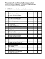
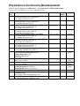
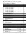
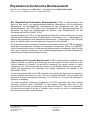
Physikalisch-Technische Bundesanstalt
Braunschweig und Berlin
Prüfbericht
Test report
Gegenstand:
Object:
Hersteller:
Manufacturer:
Typ:
Type:
Gerätenummer:
Serial number:
Auftraggeber:
Applicant:
Anzahl der Seiten:
Type testing of a voting machine for elections/referenda in Ireland
in accordance with the request of 2003-03-05 and
confirmation by PTB of 2003-03-20
N.V. Nederlandsche Apparatenfabriek NEDAP
Parallelweg 2 G / P.O.Box 105
7140 AC GROENLO
The Netherlands
Voting machine: Powervote - Integrated Election System ESI2,
Hardware version (Main) 03.00, (Connection) 01.00, (Display) 03.00
Software version (Main) 02.02, (Connection) 01.05, (Display) 02.01
R3D01028
NNE00010
(ID-number of the prototype)
(ID-number of the Programming Unit)
Department of the Environment and Local Government,
Franchise Section,
Custom House Dublin I
Ireland
25
Number of pages:
Geschäftszeichen:
PTB-8.33-PA-17/03a
Reference No.:
Datum der Prüfung:
2003-03-20 to 2003-09-04
Date of test:
Im Auftrag
Berlin, 2003-09-17
By order
Bearbeiter:
Examiner:
393 03 c
Siegel
Seal
Dr. Bronder
Sachse
Prüfberichte ohne Unterschrift und Siegel haben keine Gültigkeit. Dieser Prüfbericht darf nur unverändert weiterverbreitet werden.
Auszüge bedürfen der Genehmigung der Physikalisch-Technischen Bundesanstalt.
Test reports without signature and seal are not valid. This test report may not reproduced other than in full.
Extracts may be taken only with the permission of the Physikalisch-Technische Bundesanstalt
Physikalisch-Technische Bundesanstalt
Seite 2 zum Prüfbericht vom 2003-09-17 , Geschäftszeichen: PTB-8.33-PA-17/03a
Page 2 of test report of 2003-09-17, Reference No.: PTB-8.33-PA-17/03a
Contents
Page
1 General remarks .....................................................................................................3
2 Description of the voting machine ...........................................................................3
2.1 Identification of every voting machine and software .......................................3
2.2 Components of the system .............................................................................4
2.3 Operation mode ..............................................................................................4
2.4 Voting machine accessories ...........................................................................4
2.5 Conditions during storage and transport .........................................................4
2.6 View of the voting machine .............................................................................4
2.7 Technical data ................................................................................................4
3 Tests and results.....................................................................................................5
3.1 Test criteria .....................................................................................................5
3.2 Scope of test...................................................................................................5
3.3 Requirements and test results ........................................................................5
4 Conclusions...........................................................................................................21
4.1 Functional Tests of Hardware and Software .................................................21
4.2 Software........................................................................................................21
4.3 Documentation..............................................................................................21
4.4 Statement concerning retrofitted voting machines ........................................21
5 APPENDIX: Lists of voting machine documentations ...........................................22
Enclosures
Encl. 1:
Encl. 2:
SW-Test Report - Voting machine ESI1, dated 2003-09-17
- Software for elections in Ireland –
Software Requirements for Voting Machines for Use at Elections in Ireland,
dated 2003-03-18
Reference
PTB-Test-Report No.: PTB-8.33 - 130/02, dated 2002-08-23
PTB-Test-Report No.: PTB-8.33 - 73/01, dated 2002-01-29
Physikalisch-Technische Bundesanstalt
Seite 3 zum Prüfbericht vom 2003-09-17 , Geschäftszeichen: PTB-8.33-PA-17/03a
Page 3 of test report of 2003-09-17, Reference No.: PTB-8.33-PA-17/03a
1
General remarks
By letter of March 3, 2003 the PTB received the order to test the microprocessor-controlled voting
machine ESI2_1 of the NEDAP N.V. company with the updated hardware version 3.00 and software
version 2.00 in accordance with "Functional specification - Nedap voting system ESI2 - Powervote"
and the new "Requirements for voting machines for use at elections in Ireland DVREC-2”, dated
March 5, 2003.
The order for the test does not cover paragraphs 1.5, 4 (testing the voting machine against the Irish
statutory requirements), 9.4, 11 (testing environmental conditions of the voting machine) and paragraph 12 (safety and health requirements for the manual handling of the voting machine), nor does it
include the hardware tests of paragraphs 8.2, 8.3, 8.4, 10.2 and 10.3, which refer to paragraph 11 of
the App. Part 1 to the “Requirements for voting machines for use at elections in Ireland DVREC-2”.
After the order for the test had been placed, some corrections were made in the Hardware and in the
software of the voting machine’s main control program. The test performed by the PTB is based on the
software release versions 02.02, 01.05 and 2.01 of the main control, connection board and display
board programs. The last version of the machine and the corrected main control arrived at PTB on
June 5, 2003. The last documents arrived at PTB on Sep. 4, 2003.
The documents made available by the NEDAP company are listed in the Appendix to this Test Report.
For the sake of completeness, all paragraphs with requirements of the DVREC-2 are listed in section
3.3 of this Test Report and in enclosure 2 concerning the software requirements.
At present, the prototype of the voting machine ESI2 and the programming/reading unit (PRU) are
beeing kept at the PTB. The first prototype N7D00003 of the voting machine ESI1 will be given back to
the NEDAP company.
2
Description of the voting machine
2.1 Identification of every voting machine and software
Type, version and ID numbers of the hardware:
Voting machine (VM) with control unit (CU):
type: ESI2 version: 03.00 ID: YMDxxxxx
incl. one connection board version 01.00 and five display boards version 03.00
Programming/reading units (PRU):
type: ESI1 version: 03.00 ID: YMExxxxx
Primary ballot and backup modules:
type: ESI2
ID: YMCxxxxx
Description of the different identifier numbers (ID) YMTxxxxx:
Y
=
year of production
(A=1988, B=1989,..., K=1998, L=1999,..., N=2001)
M
=
month of production (1=January,...., O=October,.N=November, D=December)
T
=
system component identifier (C= ballot module of ESI2, D= voting machine ESI2, E= P/R unit of ESI2)
xxxxx =
five numerical characters forming the serial number of every system component
Physikalisch-Technische Bundesanstalt
Seite 4 zum Prüfbericht vom 2003-09-17 , Geschäftszeichen: PTB-8.33-PA-17/03a
Page 4 of test report of 2003-09-17, Reference No.: PTB-8.33-PA-17/03a
Version numbers and (ID) checksums of the stored programs:
Main control (Main board memory):
Pack: ESI2_1
Checksum even:
Checksum odd:
00EA28AA
010C794E
Version: 02.02
ID: Checksums
(hexadecimal)
(hexadecimal)
Connection (communication) control:
stored on the memory of the conn. board
Checksum:
Version: 01.05
ID: Checksum
(hexadecimal)
00004237
Display control:
stored on each memory of five display boards
Checksum:
0000D9A8
Version: 02.01
ID: Checksum
(hexadecimal)
2.2 Components of the system
See description in section 1.3 of "Functional Specification - Nedap Voting System ESI2 - Powervote".
2.3 Operation mode
See description in section 2 of "Functional Specification - Nedap Voting System ESI2 - Powervote".
2.4 Voting machine accessories
See description in sections 1.4 and 1.5 of "Functional Specification - Nedap Voting System ESI2 Powervote".
2.5 Conditions during storage and transport
See requirements in paragraph 11.2 of Appendix Part 1 to "Requirements for voting machines for use
at elections in Ireland DVREC-2".
2.6 View of the voting machine
See pictures and description on pages 4, 5 and 10 of "Voting machine operator´s guide". Special
descriptions are given in section 1.3 of "Functional Specification - Nedap Voting System ESI2 Powervote".
2.7 Technical data
See description in section 1.8 of "Functional Specification - Nedap Voting System ESI2 - Powervote".
Physikalisch-Technische Bundesanstalt
Seite 5 zum Prüfbericht vom 2003-09-17 , Geschäftszeichen: PTB-8.33-PA-17/03a
Page 5 of test report of 2003-09-17, Reference No.: PTB-8.33-PA-17/03a
3
Tests and results
3.1 Test criteria
Test requirements and criteria are listed in the Appendix Part 1 "Conditions for voting machines" of
"Requirements for voting machines for use at elections in Ireland DVREC-2" and in the "Functional
specification - Nedap voting system ESI2 - Powervote".
Quality criteria for the software are listed in enclosure 2.
3.2 Scope of test
The test covers inspection of the voting machine, examination of its construction and technical design,
test of the voting machine accessories and examination of the documentation submitted by the manufacturer. Some functions and operating modes of the voting machine were also tested.
The software of the voting machine was tested by inspection of the source codes and of the relevant
documentation. Moreover, static analyses and dynamic tests are carried out with the aid of suitable
software tools.
3.3 Requirements and test results
The following list includes all requirements of the Appendix Part 1 "Conditions for voting machines" of
"Requirements for voting machines for use at elections in Ireland DVREC-2" and contains some notes
which will help to understand the test results. The tests of the PTB do not include the paragraphs 1.5,
4, 9.4, 11 and 12 of the Appendix Part 1 to DVREC-2.
Details of the software test results are described in the SW-test report (see enclosure 1).
Requirement (Appendix Part 1 of "DVREC-2")
and notes
No.
Result
C o nd i t ion s f o r vo t in g mac h in es
1
(1)
General
1.1 The requirements for voting machines contained in the Functional
Specification document (version 1.9 of May 28, 2003), the electoral law and
this Appendix are mandatory.
- The agreement of the prototype of the voting machine with the details of
the functional specification document was tested exemplarily for the
different elections and the referendum. No deviations were found.
- Requirements defined in the electoral law (paragraphs 1,5 and 4) were
not examined.
- The agreement with the requirements, defined in the (next) paragraphs in
Appendix of "DVREC-2", is described in the following sections.
OK
Physikalisch-Technische Bundesanstalt
Seite 6 zum Prüfbericht vom 2003-09-17 , Geschäftszeichen: PTB-8.33-PA-17/03a
Page 6 of test report of 2003-09-17, Reference No.: PTB-8.33-PA-17/03a
(2)
1.2 The voting machine shall be constructed in line with the current general state
of technology and be designed in accordance with recognised rules of technology
applied to systems used in the machine.
OK *)
Construction:
The construction of the voting machine is in line with the current general state of
technology.
The main processor used is based on the Motorola M68000 series (16 bit data bus
and 32 bit adress bus), here in the high-speed CMOS version M68HC000 (very fast
and lower current consumption).
The storage circuits used for the main control program are two EPROM of the
27C512 type (512 kbit = 64 kByte memory capacitance).
For the storage of the error and event history and of the last vote in the case of
power loss, an EEPROM X2864A with a capacitance of 64 kbit = 8kByte is used.
Two Flash EEPROM (electrical erasable PROM) 28F010 (capacitance: 1Mbit = 128
kByte) per ballot module are used for the storage of the initial data and the votes
cast in the primary ballot module and in the backup module.
All other circuits used are fast standard CMOS circuits with good device features.
Technical design:
The technical design of the voting machine and of the systems used in the machine
is in accordance with recognised rules of technology; in particular all circuits used
are standardized circuits. The electronic circuits and elements are mainly designed
in the SMD- (source mounted device) technology.
The dimensions of the printed circuit boards (PCB´s) are not standardized. This
ensures that it is difficult for unauthorised persons to manipulate the hardware (for
instance a ballot module).
Communication between the main processor and the display and communication
boards is based on an I2C bus system, that is to say, the amount of necessary cable
conductions is reduced and the information exchange is less susceptible to external
influences.
The voting machine is not equipped with connections via which the control
programs stored could be supplemented or changed.
*) For construction and design of the software, see Encl. 1.
(3)
1.3 The voting machine shall be designed in such a way that any unauthorised
alterations of a technical nature will come to notice.
The type, the version number and the individual identifier (serial) number (ID) of
the voting machine and of the programming/reading unit are given on a type plate.
Every ballot module is identified by the individual ID-number.
The version numbers of the voting machine, the connection (communication)
board and the five display boards and the ID-numbers of the voting machine and
the installed ballot module can be displayed on, and printed out by, the voting
machine.
This enables the polling staff to compare the type, the version numbers and the
individual ID-numbers with the values given by the manufacturer in documentation
(user manual) or e.g. listed in an authorised certificate.
The compartment for holding the primary ballot module is provided with a lock and a
covering flap with holes for insertion of a seal. The primary ballot module must be
programmed for the poll(s) and the correctness of programming must be tested.
After that, the voting machine must be sealed with an official seal at the right side of
the case and transported to the polling stations.
In addition there shall be two physical seals on the cover of the electronics unit to
prevent the exchange or interference with program chips. Before the poll, the
presiding officer of the polling station must check whether the seals are still intact.
OK
Physikalisch-Technische Bundesanstalt
Seite 7 zum Prüfbericht vom 2003-09-17 , Geschäftszeichen: PTB-8.33-PA-17/03a
Page 7 of test report of 2003-09-17, Reference No.: PTB-8.33-PA-17/03a
(4)
1.4 In the case of a processor–controlled machine, any alteration of the installed
software by an unauthorised person will be detected.
OK
The program version numbers and checksums of the installed software for the
main control board, the connection (communication) board and the five display
boards can be displayed on, and printed out by, the voting machine.
This enables the polling staff to compare these program version numbers and
checksums with the values given by the manufacturer in documentation (user
manual) or e.g. listed in an authorised certificate.
(5)
1.5 The relevant statutory procedures for the preparation of a voting machine for a not tested
poll, use at a poll and at the close of a poll shall be capable of being performed by
the voting machine. The word “poll” is deemed to include more than 1 poll
(maximum 5) held simultaneously.
2
(6)
General conditions
concerning the provision of information by the voting machine
2.1 The information provided by the voting machine to the user (polling staff and
voter) must be relevant and clear.
OK
The operating elements and identifications are neatly arranged on the voting
machine. They are to a large extent self-explanatory and have been limited to what
is necessary.
The detailed description of the information given by the voting machine to the users
(polling staff and voter) is contained in the functional specification document.
(7)
2.2 The voting machine must provide the user (polling staff and voter) with
information, either on the display screen on the voting machine or on the Control
Unit or otherwise, on the steps that the user must or can take in sequence using
the voting machine and about the functions the voting machine is carrying out
pursuant to the actions taken by the user, subject to the condition that the candidate
or referendum choices recorded or vote(s) cast on the machine by the voter cannot
be related to that voter either at the time of voting or subsequently.
OK
The sequence to be followed during polling is signalled to the voter and to the
polling staff by suitable optical displays and acoustic signals.
Operation of the functions of the Control Unit, which release and block the voting
machine during polling, as well as operation of the voting machine prior to and after
polling are described in the user manual: “voting machine handbook”.
The detailed description of the information given by the voting machine to the users
(polling staff and voter) is contained in the “functional specification” document and
was checked by functional tests and software-tests (Encl. 1).
The voter cannot be identified by the voting machine, and the voting machine does
not have elements with which data of the voter can be input or stored.
(8)
2.3 The voting machine must provide a statement before polling commences and at
close of poll listing the candidates on the ballot paper, the total number of activations of the voting machine, the number of votes cast, if any, including any null
votes in the case of multiple polls, on the machine, number of deactivations of the
voting machine where a voter does not press the “CAST VOTE(S)” button and
other relevant details of the voting machine and the poll(s) concerned.
The detailed description of the information given by the voting machine to the users
(polling staff and voter) is contained in the functional specification document and
was checked by functional tests and software tests (Encl. 1).
OK
Physikalisch-Technische Bundesanstalt
Seite 8 zum Prüfbericht vom 2003-09-17 , Geschäftszeichen: PTB-8.33-PA-17/03a
Page 8 of test report of 2003-09-17, Reference No.: PTB-8.33-PA-17/03a
3
(9)
Installation
of a ballot module
3.1 Following the insertion of a programmed ballot module into the voting machine,
the voting machine shall carry out the following functions in sequence:
- check to ensure that the voting machine is functioning correctly as defined in
the Functional Specification;
OK
This requirement was checked by functional tests and software tests (Encl. 1).
- and display and/or print the contents of the memory of the primary ballot
module.
(10)
OK
This requirement was checked by functional tests and software tests (Encl. 1).
(11)
3.2 The insertion of a primary ballot module shall be controlled by means of a
physical key.
OK
The primary ballot module can be inserted and removed only by means of a red
marked "module switch key" on the backside of the voting machine This key has
two functions: First, the mechanical locking of the covering flap (with holes for
insertion of a seal) over the primary ballot module slot and, secondly the connection
to the power supply.
This requirement was checked by functional tests only.
(12)
The compartment for holding the primary ballot module shall be provided with a lock
and with a covering flap with holes for insertion of a seal.
OK
See note on (11)
This requirement was checked by functional tests only.
(13)
The machine can only be activated for voting if a module has been installed and the
lock on the ballot module slot is in the closed position.
OK
See note on (11).
If no primary ballot module has been provided, the voting machine starts with an
error message and voting is impossible.
This requirement was checked by functional tests and software tests (Encl. 1).
(14)
3.3 A back-up module shall be installed and retained in the voting machine in
accordance with the Functional Specification.
OK
If no back-up module has been provided, the voting machine starts with an error
message and voting is impossible.
This requirement was checked by functional tests and software tests (Encl. 1).
4
(15)
Displaying
ballot paper
The ballot paper displayed on the voting machine must comply with the Electoral
Act, 1992, the Electoral (Amendment) Act, 2001 or relevant Ministerial Order
under section 48 of the Act of 2001 and must be verified by statements printed
from the voting machine before voting commences and at close of poll.
not tested
Physikalisch-Technische Bundesanstalt
Seite 9 zum Prüfbericht vom 2003-09-17 , Geschäftszeichen: PTB-8.33-PA-17/03a
Page 9 of test report of 2003-09-17, Reference No.: PTB-8.33-PA-17/03a
5
Pr ep ara t io n bef or e t h e p o l l
5.1 A voting machine can only be used for a poll, after it has carried out or
supported the following steps in sequence:
- demonstrated, by way of a printed statement or on the display screen, that no
votes are recorded;
(16)
OK
By reading the display or by printing out the module contents the polling staff can
check that no votes are stored in the primary ballot module. Prior to the election,
in order to document that the ballot module is empty, print-out of a (zero) polling
result can be initiated via the “Functions” menu.
- and checked that the voting machine is functioning correctly in accordance
with the Functional Specification (Sections 2 and 8).
(17)
OK
After a primary ballot module has been inserted and the red module switch key
turned (on the backside of the voting machine) in the operating position, the
voting machine executes different self tests described in the functional specification. If an error occurs, an error message is displayed and voting is impossible.
(18)
(19)
5.2 Votes shall only be recorded if the key referred to in 3.2. is inserted in the
Control Unit.
The polling staff can release the voting machine for voting only if a red-marked
"function switch" key is inserted in the control unit and if this key is in the operating
position.
This requirement was checked by functional tests only.
Withdrawal of the key from the Control Unit will switch the voting machine to
standby and prevent votes from being recorded.
OK
OK
The "function switch" key is mechanically locked in the operating position. It can
only be withdrawn when it is turned into the standby position. In this position voting
is impossible.
This requirement was checked by functional tests only.
6
(20)
The
poll
6.1 The voting machine shall not record votes, unless it has been activated.
OK
See notes on (11) to (14) and (17) to (19)
6.2 For the recording of votes, the voting machine shall carry out or support the
following steps in sequence:
(21)
- the voting machine is activated for each voter by the presiding officer or a
person authorised by the officer- each activation will be recorded by the
voting machine;
Only the polling staff is able to activate the voting machine for the voter by
pressing the assigned button (i.e. the button assigned to the election(s) the voter
is entitled to vote for) on the control unit.
OK
Physikalisch-Technische Bundesanstalt
Seite 10 zum Prüfbericht vom 2003-09-17 , Geschäftszeichen: PTB-8.33-PA-17/03a
Page 10 of test report of 2003-09-17, Reference No.: PTB-8.33-PA-17/03a
(22)
- LED on top of each ballot paper column highlights ballot paper(s) on which a
voter is entitled to vote;
OK
This requirement was checked by functional tests and software tests (Encl. 1).
(23)
- LED displays to the right of the ballot paper shall display the marks “-- --“ on
open ballot paper(s);
OK
This requirement was checked by functional tests and software tests (Encl. 1).
(24)
- LED-displays opposite each candidate’s details or referendum choice will
display the preferences recorded on each ballot paper presented on voting
machine; in the case of a referendum, the “X” shall be in the left hand position
of the LED;
OK
This requirement was checked by functional tests and software tests (Encl. 1).
(25)
- when a preference is recorded, details will be displayed on the bottom line of
the voting machine display screen;
OK
This requirement was checked by functional tests and software tests (Encl. 1).
(26)
- provision for changing a preference for a candidate or referendum choice will
be provided by pressing the button a second time beside that candidate’s
details or referendum choice;
OK
This requirement was checked by functional tests and software tests (Encl. 1).
(27)
- a voter will be able to cast his or her vote when at least one preference has
been recorded on a ballot paper and, where there is more than 1 ballot paper
and no preference(s) is/are recorded on the second or other remaining ballot
papers, following a reminder displayed on the display screen;
OK
This requirement was checked by functional tests and software tests (Encl. 1).
(28)
- a vote will be recorded, including a null vote where applicable, in the voting
memory of the voting machine, following the pressing of the “ CAST VOTE(S)”
button.
OK
This requirement was checked by functional tests and software tests (Encl. 1).
(29)
This process shall include a check that the recording of the vote(s) cast
has/have been accomplished correctly.
OK
This requirement was checked by functional tests and software tests (Encl. 1).
(30)
- If a vote is not recorded, an error message shall be displayed.
OK
An error message will only be displayed, if no complete shut down of the voting
machine occured (see requirement 10.3).
This requirement was checked by functional tests and software tests (Encl. 1).
(31)
- If the voting machine is de-activated by the polling staff when a voter fails to
press the “CAST VOTE(S)” button, each such deactivation shall be recorded
in the memory of the voting machine;
This requirement was checked by functional tests and software tests (Encl. 1).
OK
Physikalisch-Technische Bundesanstalt
Seite 11 zum Prüfbericht vom 2003-09-17 , Geschäftszeichen: PTB-8.33-PA-17/03a
Page 11 of test report of 2003-09-17, Reference No.: PTB-8.33-PA-17/03a
- no action by the voter or polling station staff can interrupt the recording of a
vote after the “CAST VOTE(S)” button is pressed e.g. turning key on Control
Unit.
(32)
OK
This requirement was checked by functional tests and software tests (Encl. 1).
(33)
6.3 After each vote is stored, the voters panel on the voting machine shall be deactivated automatically. The voting machine will not accept any further votes until a
member of the polling station staff, operating the Control Unit, reactivates it.
OK
This requirement was checked by functional tests and software tests (Encl. 1).
(34)
6.4 Where the voter, who has been permitted to use the voting machine, does not
cast his or her vote, the polling staff can de-activate the voting machine, without
approaching the voting machine screen, by turning the key mentioned in 5.2.
OK
This requirement was checked by functional tests and software tests (Encl. 1).
(35)
Any preference(s) entered on the voting machine screen will not be recorded as a
vote. A new activation is only possible after use of the key mentioned in 5.2.
OK
This requirement was checked by functional tests and software tests (Encl. 1).
(36)
A deactivation of the voting machine, following the non-use of the “CAST
VOTE(S)” button, shall be recorded in the memory of the voting machine.
OK
This requirement was checked by functional tests and software tests (Encl. 1).
(37)
6.5 Once the voter has pressed the "CAST VOTE(S)" button, the voting machine
shall not provide information about any preference(s) recorded or vote cast by a
voter.
OK
This requirement was checked by functional tests and software tests (Encl. 1).
(38)
6.6 The number of votes cast, including null votes in the case of multiple polls, will
be displayed on the Control Unit and on the voting machine in stand-by mode.
OK
This requirement was checked by functional tests and software tests (Encl. 1).
7
(39)
Displaying and printing
the total number of votes at close of poll
7.1 The voting machine shall display, where necessary, the total number of votes
cast and, where applicable, the number of null votes;
At close of the poll the polling staff must turn the function switch key in the operating
position while pressing the function button. The voting machine is now in the
"Function" mode and the polling staff can close poll and show the votes cast on the
display.
The number of null votes can be printed out, see note on (40).
OK
Physikalisch-Technische Bundesanstalt
Seite 12 zum Prüfbericht vom 2003-09-17 , Geschäftszeichen: PTB-8.33-PA-17/03a
Page 12 of test report of 2003-09-17, Reference No.: PTB-8.33-PA-17/03a
(40)
additionally it shall print, where necessary, the total number of voters who were
permitted to use the machine (activations); the total number of votes cast, the
number of null votes and the total number of deactivations.
OK
The print out of the poll result includes the number of votes cast, the number of null
votes, the number of activations and the number of deactivations
This requirement was checked by functional tests and software tests (Encl. 1).
(41)
7.2 Activation of the voting machine for the display and printing of the information
referred to in paragraph 7.1 shall be accomplished by means of the key referred to
in paragraph 5.2.
OK
This requirement was checked by functional tests and software tests (Encl. 1).
(42)
The back-up module shall be checked to ensure that any existing data in the
module is deleted, before the contents of the primary ballot module are copied to
the back up module.
OK
This requirement was checked by functional tests and software tests (Encl. 1).
(43)
Withdrawal of the key from the Control Unit will automatically stop the printing
process.
OK
Withdrawal of the function switch key automatically switches the voting machine to
the stand-by mode because the key is mechanically locked in the operation mode
and can only be withdrawn in the stand-by mode. All current activities of the voting
machine will be aborted.
This requirement was checked by functional tests only.
(44)
7.3 After displaying or printing the total number of votes cast etc, the voting machine
can only be re-activated for the casting of votes after the insertion of a new
programmed ballot module.
OK
After the total number of votes cast has been displayed or printed, the primary
ballot module used is locked for further casting of votes. The election can only be
continued by insertion of a newly programmed primary ballot module.
A copy of the contents of the previous primary ballot module is still present in the
backup module. If the polling staff displays or prints out the polling results for the
next primary ballot module, the previous copy will be overwritten.
8
(45)
Reliability
and
security
of the voting machine
8.1 A vote recorded in the primary ballot module must be the vote that the voter has
cast.
OK
This requirement was checked by software tests (Encl. 1) only.
(46)
The voting machine must be capable of recording votes on 5 ballot papers
(maximum 90 preferences) simultaneously as per paragraph 13. The capacity of the
ballot module is set out in paragraph 1.8 of the Functional Specification.
This requirement was checked by functional tests and software tests (Encl. 1).
OK
Physikalisch-Technische Bundesanstalt
Seite 13 zum Prüfbericht vom 2003-09-17 , Geschäftszeichen: PTB-8.33-PA-17/03a
Page 13 of test report of 2003-09-17, Reference No.: PTB-8.33-PA-17/03a
(47)
8.2 Subject to 10.3, a cast vote must not be lost by a power failure, the failing of one
component, the effect of environmental conditions detailed in paragraph 11.1,
through normal use or through failures in the operation of the voting machine.
OK
a) This requirement was checked by software tests (Encl. 1) only.
b) For tests regarding environmental conditions, see notes on paragraph 11.1.
(48)
8.3 The installed ballot module and its contents must be fully maintained in case of
a power failure, the effect of environmental conditions as set out in paragraph 11.1,
through normal use or through failures in the operation of the voting machine.
OK
a) This requirement was checked by software tests (Encl. 1) only.
b) For tests regarding environmental conditions, see notes on paragraph 11.1.
(49)
8.4 The functions of the voting machine must be fully maintained in the event of a
power failure, or exposure to the environmental conditions as detailed in 11.1.
OK
The printer and the fluorescent lamp do not work if a battery is used (see list 1
No. 1 “functional specification” in the Appendix of this Test Report).
a) This requirement was checked by software tests (Encl. 1) only.
b) For tests regarding environmental conditions, see notes on paragraph 11.1.
(50)
8.5 The storing of votes in the ballot module must be made in such a way so as to
ensure security and continuous self-checking of all data.
OK
This requirement was checked by software tests (Encl. 1) only.
(51)
Each vote will be stored twice in each of 2 independent IC’s within the ballot module
i.e. each vote is stored four times in the ballot module.
OK
This requirement was checked by software tests (Encl. 1) only.
(52)
As each single preference is recorded a checksum (a security code applied over a
number of bytes based upon Hamming Code which is an international standard) is
calculated and stored in the RAM.
OK
This requirement was checked by software tests (Encl. 1) only.
(53)
When the voter presses the “CAST VOTE(S)” button all checksums of all
preferences stored in RAM shall be checked.
OK
This requirement was checked by software tests (Encl. 1) only.
(54)
As the voting machine stores preferences, a read back of the last byte of data
written should be made as a further check.
OK
This requirement was checked by software tests (Encl. 1) only.
(55)
After storing all preferences, the system should check all of these again and their
checksums.
OK
This requirement was checked by software tests (Encl. 1) only.
(56)
The last step is a check of all preferences stored from all voters. This sequence is
repeated for every voting cycle.
This requirement was checked by software tests (Encl. 1) only.
OK
Physikalisch-Technische Bundesanstalt
Seite 14 zum Prüfbericht vom 2003-09-17 , Geschäftszeichen: PTB-8.33-PA-17/03a
Page 14 of test report of 2003-09-17, Reference No.: PTB-8.33-PA-17/03a
(57)
In the event that a discrepancy occurs in the checksums, an error message is
generated.
OK
This requirement was checked by software tests (Encl. 1) only.
(58)
This message is shown on the voting machine display and on the Control Unit
display enabling the presiding officer to take appropriate action.
OK
This requirement was checked by software tests (Encl. 1) only.
(59)
8.6 The voting machine should, as far as is reasonably and technically possible,
avoid or restrict the possibilities of accidental or intentional incorrect use.
OK
Only the buttons on the voters panel necessary for polling are free for use by the
voter. This information is programmed in the primary ballot module. Pressing of
other buttons will not have any effect.
The information given to the voter and the polling staff during polling is also
programmed in the primary ballot module. Programming must be carried out and
checked by the central office one ore more days before the poll.
Malfunctions of the voting machine during the election come to notice because of
the cyclic internal self-check procedures inherent in the voting machine.
(60)
8.7 The voting machine shall have a physical seal on the cover of the electronics
unit to prevent the exchange or interference with program chips.
OK *)
*) Provisions have been made at the prototype of the machine for a seal to be put
on the electronic panel. A local inspection on serial machines is required.
(61)
8.8 The votes shall be stored randomly in the ballot module and must not be
displayed or printed on the voting machine.
OK
This requirement was checked by functional tests and software tests (Encl. 1).
The vote part of the ballot module contains about 30 000 storage places where part
of a vote can be stored. The vote storage program does not generate random numbers of its own to determine the random addresses where a vote is stored. For the
calculation of the addresses for storage of the votes, a random number is determined by a timer counter.
The voting machine is equipped with a timer interrupt which is enabled at power-on.
This interrupt takes place every 8 milliseconds, and the timer counter increments at
each interrupt. This actual random value of the timer counter is passed on to the
vote storage program each time a new vote storage address is determined.
In no case will the votes be stored in sequential order. As the vote storage software
program does not generate random numbers of its own to determine the random
addresses where a vote is stored, it is not possible for anyone familiar with the
software to find out where the voter’s preferences are stored.
9
(62)
Operability
9.1 The voting machine shall be configured so that a voter can only carry out voting
actions on it.
See notes on paragraph 8.6.
This requirement was checked by functional tests and software tests (Encl. 1).
OK
Physikalisch-Technische Bundesanstalt
Seite 15 zum Prüfbericht vom 2003-09-17 , Geschäftszeichen: PTB-8.33-PA-17/03a
Page 15 of test report of 2003-09-17, Reference No.: PTB-8.33-PA-17/03a
(63)
9.2 Voting on the voting machine must be easy to understand.
OK
Most of the explanations and instructions shown to the voter and the polling staff on
the displays must be programmed in the primary ballot module for each poll. These
instructions can be updated depending on the experience gained in the last poll.
In addition, the "voting machine handbook" for the polling staff and a short manual
for the voter should be available in each polling station.
(64)
9.3 The carrying out of an action by the presiding officer or by the voter must lead to
a visible, audible or tangible feedback signal within one second.
OK
Actions carried out by the presiding officer or the voter lead to a change of both, the
voter’s display and the officer’s display.
If the voter presses a "programmed" button on the voter’s panel, a short beep will
be generated. If he presses the "cast votes" button, the beep will be longer; if a
mistake is made, some short beeps will be generated.
(65)
9.4 When the voter records a preference or casts a vote by means of the buttons on not tested
the voting machine, the following requirements shall apply to the buttons:
- minimum dimensions: square 10 x 10 (mm), round 10 (mm);
- maximum operating force for the selection of a candidate: 4(N);
- maximum travel when buttons are pushed for selection of a preference for a
candidate: 6(mm);
- minimum travel when buttons are pushed: 0(mm).
This paragraph is not covered by the order for testing.
10
(66)
R e p o r t i n g and s o l u t i o n of problems
10.1 The voting machine shall, as far as possible, be equipped with a diagnostic
mechanism so that after each action that has been performed within the voting
machine, the mechanism can detect defects or incorrect working of the different
components of the voting machine and their associated communication channels.
OK
Whenever a voter presses the "cast votes" button, the voting machine executes
different self tests and checksum tests which are described in the functional
specification. If an error occurs, an error message is displayed and the voting
machine turns into the error-state.
(67)
These actions must include the steps that the voter or the polling staff can perform.
The voting machine must report a defect or incorrect working to the user.
OK
See note on (66).
(68)
10.2 In the event of a power failure between 500 msec and 2000 msec of pressing
the CAST VOTE(S) button, a vote stored in the Eeprom of the machine shall not be
lost, providing there is no fatal machine failure on restoration of power.
OK
This requirement was checked by software tests (Encl. 1) only.
(69)
10.3 In the event of a voting machine failure that affects the vote storage process
(between 500 msec and 2000 msec of pressing the “CAST VOTE(S)” button),
unless the failure is such as to cause a complete shut down of the machine, an
error message shall be displayed e.g. error no. xxxx- vote not stored.
This requirement was checked by software tests (Encl. 1) only.
*) While an error code is displayed, the message is not displayed, see note (72).
OK *)
Physikalisch-Technische Bundesanstalt
Seite 16 zum Prüfbericht vom 2003-09-17 , Geschäftszeichen: PTB-8.33-PA-17/03a
Page 16 of test report of 2003-09-17, Reference No.: PTB-8.33-PA-17/03a
(70)
10.4 The diagnostic mechanism shall not be accessible to or be capable of being
switched off by the user.
OK
No switching mechanism for the user has been provided.
(71)
10.5 The diagnostic mechanism must provide the user with messages (text or code)
that support and speed up the trouble shooting procedure.
OK
See note on (66).
(72)
10.6 The meaning of the fault messages generated by the diagnostic mechanism
and the actions to be taken with respect to each fault message must be clearly
stated in the voting machine user manual for help desk staff.
OK
The meanings of all error codes are listed in a special document in addition to the
user manual. See note on (100) and list (3) “Documentation” No. 4 in the Appendix
of this Test Report.
11
(73)
Environmental conditions
(derived from [OIML-11], [IEC-60839], [IEC-60068-2] or as amended,
adapted or extended by or under any subsequent version of these
documents or replacement documents)
11.1 Environmental conditions referred to in 8.2, 8.3 and 8.4 are:
• Environmental temperature: [IEC-60839-1-3], [IEC-60068-2], 5˚C to 40˚C.
• Relative humidity: [IEC-60068-2] 85% at 40˚C (upper limit) “non
condensing”.
• Power supply voltage: [IEC-60839-1-3] 230V + 10%, -10%; 50Hz + 2%.
• Power supply cuts (current interruption): the voting machine must be
equipped with a connection to an emergency power (emergency power
generator or batteries).
• Power cuts with short time durations: [IEC-60839] 500 ms (black outs) and
suppression up to 75% of the nominal voltage (brown out) must not lead to
loss of function and information.
• Electromagnetic compatibility (EMC); this equipment must comply with
EN 50081-1 and EN 50082-1, for which the following tests apply:
- Fast transients: [EN 50082-1];
1 kV on the power supply surge test: [EN 50082-1];
1 kV in differential mode, 2 kV in common mode.
- Air discharge: [EN 50082-1]; ESD test with 16 kV discharges.
- Electromagnetic disturbances: [EN 50082-1];
Radiated: 80 to 100 MHz, field strength 3 V/m, modulated.
Conducted, via power supply: 0.150 MHz to 80 MHz, 3 V.
- Insulation: [IEC-60839]; > 10 MOhm under all temperature and humidity
conditions the insulation of the power supply circuit must be resistant to a
voltage of 2 kV between the phase and the 0 wire connected together and
to earth during 10 seconds.
• Housing: [IEC-60529].
- Drip water proof, IP x 1 (valid for all components of the machine that are
in direct contact with the voter).
• Energy consumption: an energy consumption such that the emergency
power supply (for instance a battery) can maintain the voting machine fully
operational for at least 8 hours without replacement.
This paragraph is not covered by the order for testing.
not tested
Physikalisch-Technische Bundesanstalt
Seite 17 zum Prüfbericht vom 2003-09-17 , Geschäftszeichen: PTB-8.33-PA-17/03a
Page 17 of test report of 2003-09-17, Reference No.: PTB-8.33-PA-17/03a
(74)
11.2 The functions of the voting machine will be maintained after being exposed to
the following conditions during storage:
- Environmental temperature: [IEC-60068-2] -25˚C to +70˚C.
- Relative humidity: [IEC-60068-2]; 95 % at 40˚C (upper limit) “non condensing”.
- Temperature change: [IEC-60068-2]; 25˚C to 30˚C.
- Mechanical vibration: [IEC-60068-2].
- Random: acceleration spectral density 1 m/s3 (100 to 200 Hz),
0.3 m/s3 (200 to 2000 Hz) during 1 hour per direction.
- Sine wave form: 10 m/s (10 to 200 Hz) 15 m/s (200 to 500 Hz).
- Free drop: [IEC-60068-2]; flat, 2 x per side from a height of 0.25 m.
- Tilt: [IEC-60068-2]; along each edge of the packaging.
not tested
This paragraph is not covered by the order for testing.
12
(75)
Manual
handling
of
voting
machine
The manufacturer shall ensure, as far as is reasonably practicable, that the voting
machine case is designed and constructed so as to be safe and without risk to the
safety and health when moved, opened or closed by persons employed at a poll.
The design and build shall be such as to enable the returning officer (the
employer) to comply with Council Directive 90/269/EEC of 29 May 1990 and the
Safety, Health and Welfare at Work Act, 1989 (sections 6, 7, 8, 9, 10 and 11) –
copies at Part 2 of this Appendix.
not tested
This paragraph is not covered by the order for testing.
(76)
Regard shall also be had to the following publications of the European Agency for
Safety and Health at Work:
• Factsheet (No. 10) on work-related low back disorders; and
• Research on work related low back disorders report (October, 2000)
(htp://agency.osha.eu.int/publications/reports/lowback/) – in particular the IS0
ergonomic standards listed in Chapter 4.4 (see item 3 in Part 2 of the Appendix).
not tested
This paragraph is not covered by the order for testing.
13
(77)
Conditions
for the use of voting machines for two or more polls simultaneously
The voting machines may be used for one, two or more (maximum 5) polls that are
held simultaneously, including an election and a referendum.
OK
The number of polls (including a referendum), which can be held simultaneously, is
described in the functional specification in section 1.8.
(78)
The voting machine shall be equipped in such a way that it fulfils the following
requirements:
- the designation of the selection buttons for each ballot paper is stored in tabular
form in the ballot module;
This requirement was checked by software tests (Encl. 1) only.
OK
Physikalisch-Technische Bundesanstalt
Seite 18 zum Prüfbericht vom 2003-09-17 , Geschäftszeichen: PTB-8.33-PA-17/03a
Page 18 of test report of 2003-09-17, Reference No.: PTB-8.33-PA-17/03a
(79)
- the voting machine can be activated for the voter for a maximum of 5 polls;
OK
The number of polls (including a referendum), which can be held simultaneously, is
described in the functional specification in section 1.8.
This requirement was checked by functional tests and software tests (Encl. 1).
(80)
- the ballot papers displayed on the voting machine are clearly separated from
each other;
OK
The voter’s panel is provided with five display boards separated from one another
and arranged in columns.
(81)
- the voter can record preferences starting on any ballot paper. The preferences
will start from 1 on each ballot paper (except a referendum ballot paper). The
voter may switch between ballot papers until he/she has finished recording
his/her preferences;
OK
This requirement was checked by functional tests and software tests (Encl. 1).
(82)
- the cast votes are stored randomly and cannot be displayed or printed on the
voting machine.
OK
The mode of storing votes is described in List 1 No. 3 and 7 (vote storage) in the
Appendix of this Test Report.
In no case will the votes be stored in sequential order. See notes on paragraph 8.8.
There is no possibility to display or print the cast votes on the voting machine.
14
Documentation
14.1 The voting machine must be supplied with the following documentation:
(83)
- system documentation;
OK
See list 1 "Technical documentation of NEDAP" in the Appendix of this Test Report.
(84)
- development documentation;
OK
See list 1 "Technical documentation of NEDAP" in the Appendix of this Test Report.
(85)
- test documentation;
OK
See list 2 "Test documentation of NEDAP" in the Appendix of this Test Report.
(86)
- a user manual;
OK
See list 3 "Documentation: overview and user manuals" No. 3 and No. 4 in the
Appendix of this Test Report.
(87)
- instructions for the voter.
See list 3 "Documentation: overview and user manual" No. 5 in the Appendix of this
Test Report.
OK
Physikalisch-Technische Bundesanstalt
Seite 19 zum Prüfbericht vom 2003-09-17 , Geschäftszeichen: PTB-8.33-PA-17/03a
Page 19 of test report of 2003-09-17, Reference No.: PTB-8.33-PA-17/03a
14.2 The system documentation shall describe:
(88)
(a) the working principle of the voting machine and the additional equipment and a
description of the construction (both electronic and mechanical) explained with:
- construction drawings,
- block diagrams, electronic and wiring diagrams, printed circuit board layouts.
OK
See list 1 "Technical documentation of NEDAP" No. 9 in the Appendix of this Test
Report.
(89)
(b) specifications of the environmental and operating conditions for normal
operation, storage and transport of the voting machine;
OK
See list 1 "Technical documentation of NEDAP" No. 8 in the Appendix of this Test
Report.
(90)
(c) identification data, including:
- serial, type and ordering numbers,
- production and/or delivery date,
- electrical connection/power supply.
This identification data must also be adequately indicated on the voting machine
and the additional equipment.
OK
See list 1 No. 1 “functional specification” in the Appendix of this Test Report.
This identification data are indicated on a type plate and on the display or printout of
the voting machine. See notes (3) and (4) on paragraphs 1.3 and 1.4.
14.3 The development documentation must include:
(91)
(a) a functional specification of the voting machine and programming unit;
OK
See list 1 No. 1 in the Appendix of this Test Report.
(92)
(b) the technical design of the voting machine and programming unit;
OK
See list 1 "Technical documentation of NEDAP" No. 3 to 13 and No. 23 in the
Appendix of this Test Report.
(93)
(c) listings of the application source codes;
OK
See list 1 "Technical documentation of NEDAP" No. 24 to 27 in the Appendix of this
Test Report.
(94)
(d) a quality plan.
OK
See list 2 "Test documentation of NEDAP" No. 9 in the Appendix of this Test
Report.
14.4 The test documentation must describe
(95)
which measurements the manufacturer used at the verification, the validation and
the testing of components of the voting machine (including software)
and must include at least:
OK
Physikalisch-Technische Bundesanstalt
Seite 20 zum Prüfbericht vom 2003-09-17 , Geschäftszeichen: PTB-8.33-PA-17/03a
Page 20 of test report of 2003-09-17, Reference No.: PTB-8.33-PA-17/03a
(96)
- a test plan that describes the way in which the functions of the machine and
programming unit are tested;
OK
(97)
- software module test report that describes the results of the module tests;
OK
(98)
- software integration test report(s) that describe the results of the integration tests;
OK
(99)
- software system test plan and report(s) containing the system test plan (test
specification) and results.
OK
14.5 The user manual
(100)
The user manual must include:
- manual handling requirements (Council Directive 90/269/EEC of 29 May 1990)
(including a list of error codes and explanations);
OK
In a special section “Troubleshooting” of the user manual for the polling staff
there are listed 21 error codes (with instructions for the polling staff) which appear
when the vote has not been stored.
In addition to the user manual there is a document with a full list of error/event
codes (and messages) for help desc staff.
See list 3 "Documentation" No. 4 in the Appendix of this Test Report.
(101)
- instructions for unpacking, opening, connecting and putting the voting machine
into operation;
OK
(102)
- operating instructions for the adjustment of the voting machine and security and/or
locking;
OK
(103)
- operating instructions for the members of the polling station;
OK
(104)
- maintenance instructions;
OK
(105)
- storage instructions.
OK
14.6 Instructions for the voter
(106)
This document shall contain the instructions for a voter to use the voting machine.
OK
Physikalisch-Technische Bundesanstalt
Seite 21 zum Prüfbericht vom 2003-09-17 , Geschäftszeichen: PTB-8.33-PA-17/03a
Page 21 of test report of 2003-09-17, Reference No.: PTB-8.33-PA-17/03a
4
Conclusions
4.1 Functional Tests of Hardware and Software
The described tests of the voting machine did not give cause for objections.
The identification data of the hard- and software can be seen on the display and on the printout of the
voting machine (see notes (3) and (4) on paragraphs 1.3 and 1.4).
4.2 Software
The software test report (Encl. 1) makes some recommendations for an improvement of the software
in case a further development of the software is envisaged (see summary of the software test report).
The operativeness of the machine is not, however, affected by this in any way whatsoever.
The software tests did not give cause for objections.
4.3 Documentation
The documents listed have been submitted and are complete.
4.4 Statement concerning retrofitted voting machines
The electronic construction of the metal electronics compartment has been further developed compared with the hardware version of the ESI1 (see list 1 “Technical documentation of NEDAP“ No. 28
“Differences between new and retrofit machines, Revision A02” in the App. of this Test Report).
This change is not required by DVREC-2. So both, the old and the new version of this hardware compartment can be used with the new software version 02.02 without influencing the tested properties.
The cabinet and other components of the voting machine, like the connection board and the display
boards, are not influenced and are completely equivalent to the version of ESI2.
That is why it is recommended to mark the retrofitted voting machines and programming units appropriately on their type plates. So it is possible to notice the difference at any time if necessary.
Physikalisch-Technische Bundesanstalt
Seite 22 zum Prüfbericht vom 2003-09-17 , Geschäftszeichen: PTB-8.33-PA-17/03a
Page 22 of test report of 2003-09-17, Reference No.: PTB-8.33-PA-17/03a
5
APPENDIX: Lists of voting machine documentations
No.
1
(1) Technical documentation of NEDAP
functional specification
NEDAP voting system ESI2, powervote,
doc. number: 8011915.18.01
doc. version: 1.9; SW. Version 02.02
Release date
No. of
pages
May 28, 2003
62
Language
English
2
executable file NWS.EXE for Ireland version 2.02
on 3,5" disc (for test handling only)
Jun. 03, 2003
1
English
3
technical specification NEDAP voting system
ESI1 -vote storage- doc. version:1.2
Hardware Wahlgerät ESD1
doc. version 1.1
Hardware modifications main board; from HMT to
SMT Revision A01
doc. number: 7822596.19.01
hardware specification NEDAP voting system
ESI1- vote storage after interrupt, doc. version:1.0
Dec. 14, 2001
10
English
Jan. 02, 1998
160
German
Apr. 23, 2003
4
English
Oct. 19, 2001
4
English
Oct., 2001
20
English
Mar. 26, 2003
4
English
various
88
May 08, 2003
16
English /
Dutch
English
Oct. 5, 2001
25
English
May 05, 2003
16
English
Aug. 05, 2003
39+1
English
Feb. 18, 2003
3
English
Apr. 03, 2003
1
English
4
5
6
7
8
9
reliability of the voting machine ESI1
doc. version: 1.1
validation plan for environmental conditions for
voting machine ESI2
doc. number: 9556583.19.11 Rev. A01
schemes, pcb-drawings and parts lists for ESI2
10
interface specification,
voters panel & main processor board
doc. number: 8011966.19.01 Rev. B
11
hardware and software specifications;
connection board voting machine Ireland ESI1
version 0.0
hardware and software specifications,
display board voting machine Ireland ESI1
doc. number: 8011923.19.02 Rev. 0.3
12
13
14
15
detailed software design
NEDAP voting system ESI2
ESI2_1 software;
doc. number: 8011915.19.01 doc. version: 1.2
Update report software main board ESI2
SW version 01.04 to 02.00 Revision A
doc. number: 8011915.01.01
Update report software main board ESI2
SW version 02.00 to 02.01 Revision A
doc. number: 8011915.01.01
Physikalisch-Technische Bundesanstalt
Seite 23 zum Prüfbericht vom 2003-09-17 , Geschäftszeichen: PTB-8.33-PA-17/03a
Page 23 of test report of 2003-09-17, Reference No.: PTB-8.33-PA-17/03a
No.
16
17
18
19
20
21
22
23
24
25
26
27
28
29
(1) Technical documentation of NEDAP
Update report software main board ESI2
SW version 02.00 to 02.01 Revision A
doc. number: 8011915.01.02
Update report software main board ESI2
SW version 02.01 to 02.02 Revision A
doc. number: 8011915.01.03
Update report software display print ESI2
SW version 01.06 to 02.00 Rev. A
doc. number: 8011923.01.01
Update report software display print ESI2
SW version 02.00 to 02.01 Rev. A
doc. number: 8011923.01.02
Update report software display print ESI2
SW version 02.00 to 02.01 Rev. A
doc. number: 8011923.01.02
Update report software connection print ESI1
SW version 01.04 to 01.05 Rev. A
doc. number: 8011966.01.01
Update report software connection print ESI2
SW version 01.04 to 01.05 Rev. A
doc. number: 8011966.01.01
Project overview Nedap voting system ESI2
doc. number: 9556583.19.03 Rev. A
source code,
- main control program ESI2 V02.00
- connection print V1.04
- display print V02.00
on 3,5“ disc
source code, main control program ESI2
V02.01 on 3,5“ disc
source code, main control program ESI2
V02.02 on 3,5“ disc
source code ESI2,
- connection print V01.05 and
- display print V02.01 on 3,5" disc
Differences between new and retrofit voting
machines (ESI2)
doc. number: TB7174-05E003 Rev. A02
Cast vote beep- interrupt; ESI2
doc. Number 8011915.19.29 Rev. A02
Release date
No. of
pages
Apr. 22, 2003
3
Language
English
Jun. 03, 2003
1
English
Feb. 18, 2003
1
English
Mar 19, 2003
1
English
Apr. 23, 2003
1
English
Mar. 19, 2003
1
English
Apr. 22, 2003
1
English
May 08, 2003
9
Mar. 17, 2003
1
English/
Dutch
Apr. 23, 2003
1
Jun. 06, 2003
1
Apr. 23, 2003
1
English/
Dutch
English/
Dutch
English/
Dutch
May 22, 2003
1
English
Aug. 18, 2003
1
English
Physikalisch-Technische Bundesanstalt
Seite 24 zum Prüfbericht vom 2003-09-17 , Geschäftszeichen: PTB-8.33-PA-17/03a
Page 24 of test report of 2003-09-17, Reference No.: PTB-8.33-PA-17/03a
No.
1
2
3
4
5
6
7
8
9
10
No.
1
2
3
4
5
(2) Test documentation of NEDAP
Overview ESI2 software tests
doc. Number 9556583.19.12 Rev. A03
test results
- integration tests software main board ESI2
doc. number: 8011915.19.20 Rev. 1.1
- functions tests software main board ESI2
doc. number: 8011915.19.22 Rev. 1.1
- driver tests software main board ESI2
doc. number: 8011915.19.23 Rev. 1.1
- event and error tests software main board ESI2
doc. number: 8011915.19.24 Rev. 1.2
- communication tests software main board ESI2
doc. number: 8011915.19.25 Rev. 1.1
- state machine tests software main board ESI2
doc. number 8011915.19.26 Rev. C
connection board function tests
doc. number: 8011966.19.20 Rev. A
display board function test results Rev. A
doc. number: 8011923.19.20
verification tests smd mainboard voting machine
doc. number: 7822596.19.10 Rev. 1.4
test results smd mainboard voting machine ESI2
doc. number: 7822596.19.20 to .42
Update report function tests software main board
ESI2
doc. number: 8011915.19.28 Rev. A
Update report event and error tests software main
board ESI2
doc. number: 8011915.19.27 Rev. A
test description vote storage at power failure
NEDAP voting system ESI1- vote storage,
doc-version: 1.1
controlplan stemcomputer ESI2
doc-code: KP0015 ESI2 Rev. 01
(3) Documentation: overview and user manuals
Documentation overview
doc. number: TB7174-05E001 Rev. A04
Documentation status ESI2
doc. number: TB7174-05E002 Rev.A10(old version)
NEDAP Powervote voting machine
operator´s guide
Version 0907-2
List of error/event messages relating to
voting machines type ESI2
Version 0111
voting instructions
(for the voter)
without Version number
Release date
No. of
pages
Aug. 27, 2003
4
Language
English
Aug. 06, 2003
11
English
Aug. 14, 2003
27
English
Aug. 14, 2003
12
English
Sep. 03, 2003
18
English
Aug. 06, 2003
5
English
Sep.03 , 2003
9
English
Apr. 29, 2003
31
English
Feb. 29, 2003
16
English
May 09, 2003
2
English
Jan.-May 2003
38
English
Jun. 03, 2003
1
English
Jun. 03, 2003
1
English
Dec. 17, 2001
2
English
May 08, 2003
7
English
Release date
No. of
pages
Jun. 04, 2003
7
Language
Aug. 28, 2003
5
without date
sent:
Sep. 17, 2003
without date
sent:
Sep. 03, 2003
without date
sent:
Jun. 13, 2003
17
English/
Dutch
English/
Dutch
English
8
English
1
English
Physikalisch-Technische Bundesanstalt
Seite 25 zum Prüfbericht vom 2003-09-17 , Geschäftszeichen: PTB-8.33-PA-17/03a
Page 25 of test report of 2003-09-17, Reference No.: PTB-8.33-PA-17/03a
Die Physikalisch-Technische Bundesanstalt (PTB) in Braunschweig und
Berlin ist das natur- und ingenieurwissenschaftliche Staatsinstitut und die technische
Oberbehörde der Bundesrepublik Deutschland für das Messwesen und Teile der
Sicherheitstechnik. Die PTB gehört zum Dienstbereich des Bundesministeriums für
Wirtschaft. Sie erfüllt die Anforderungen an Kalibrier- und Prüflaboratorien auf der
Grundlage der DIN EN ISO/IEC 17025.
Zentrale Aufgabe der PTB ist es, die gesetzlichen Einheiten in Übereinstimmung mit dem
Internationalen Einheitensystem (SI) darzustellen, zu bewahren und - insbesondere im
Rahmen des gesetzlichen und industriellen Messwesens - weiterzugeben. Die PTB steht
damit an oberster Stelle der metrologischen Hierarchie in Deutschland.
Zur Sicherstellung der weltweiten Einheitlichkeit der Maße arbeitet die PTB mit anderen
nationalen metrologischen Instituten auf regionaler europäischer Ebene in EUROMET
und auf internationaler Ebene im Rahmen der Meterkonvention zusammen. Das Ziel wird
durch einen intensiven Austausch von Forschungsergebnissen und durch umfangreiche
internationale Vergleichsmessungen erreicht.
The Physikalisch-Technische Bundesanstalt (PTB) in Braunschweig and Berlin is the
national institute for science and technology and the highest technical authority of the
Federal Republic of Germany for the field of metrology and certain sectors of safety
engineering. The PTB comes under the auspices of the Federal Ministry of Economics. It
meets the requirements for calibration and testing laboratories as defined in the
EN ISO/IEC 17025.
It is the fundamental task of the PTB to realize and maintain the legal units in compliance
with the International System of Units (SI) and to disseminate them, above all within the
framework of legal and industrial metrology. The PTB thus is on top of the metrological
hierarchy in Germany.
To ensure worldwide coherence of measures, the PTB cooperates with other national
metrology institutes within EUROMET on the regional European level and on the
international level within the framework of the Metre Convention. The aim is achieved by
an intensive exchange of results of research work carried out and by comprehensive
international comparison measurements.
Physikalisch-Technische Bundesanstalt
Bundesallee 100
38116 Braunschweig
Deutschland
Abbestraße 2-12
10587 Berlin
Deutschland