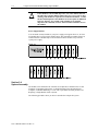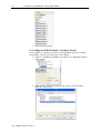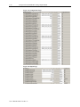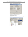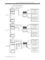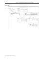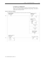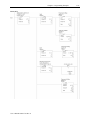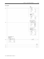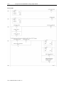
1
User’s Manual 0300217-03 Rev. A Compact™ I/O Isolated HART Analog Module Catalog Number: 1769sc-OF4IH ii Compact™ IO Isolated HART Analog Output Module User’s Manual 0300217-03 Rev. A Table of Contents iii Table of Contents CHAPTER 1 MODULE OVERVIEW ..................................................................................................................... 1‐1 SECTION 1.1 GENERAL DESCRIPTION ............................................................................................................................. 1‐1 SECTION 1.2 DATA FORMATS ....................................................................................................................................... 1‐1 SECTION 1.3 HARDWARE FEATURES .............................................................................................................................. 1‐2 1.3.1 General Diagnostic Features ..................................................................................................................... 1‐3 SECTION 1.4 SYSTEM OVERVIEW .................................................................................................................................. 1‐3 1.4.1 System Operation ..................................................................................................................................... 1‐3 SECTION 1.5 MODULE OPERATION ............................................................................................................................... 1‐4 CHAPTER 2 QUICK START FOR EXPERIENCED USERS ......................................................................................... 2‐1 SECTION 2.1 BEFORE YOU BEGIN .................................................................................................................................. 2‐1 SECTION 2.2 REQUIRED TOOLS AND EQUIPMENT ............................................................................................................ 2‐1 SECTION 2.3 WHAT YOU NEED TO DO .......................................................................................................................... 2‐1 CHAPTER 3 INSTALLATION AND WIRING .......................................................................................................... 3‐1 SECTION 3.1 COMPLIANCE TO EUROPEAN UNION DIRECTIVES ........................................................................................... 3‐1 3.1.1 EMC Directive ............................................................................................................................................ 3‐1 3.1.2 Low Voltage Directive ............................................................................................................................... 3‐1 3.1.3 CE Safety ................................................................................................................................................... 3‐1 SECTION 3.2 POWER REQUIREMENTS ............................................................................................................................ 3‐2 SECTION 3.3 GENERAL CONSIDERATIONS ....................................................................................................................... 3‐2 3.3.1 Hazardous Location Considerations .......................................................................................................... 3‐2 3.3.2 Prevent Electrostatic Discharge ................................................................................................................ 3‐2 3.3.3 Remove Power .......................................................................................................................................... 3‐3 3.3.4 Selecting a Location .................................................................................................................................. 3‐3 SECTION 3.4 SYSTEM ASSEMBLY ................................................................................................................................... 3‐4 SECTION 3.5 MOUNTING ............................................................................................................................................. 3‐5 3.5.1 Minimum Spacing ..................................................................................................................................... 3‐5 3.5.2 Panel Mounting ........................................................................................................................................ 3‐6 3.5.3 DIN Rail Mounting .................................................................................................................................... 3‐7 SECTION 3.6 REPLACING A SINGLE MODULE WITHIN A SYSTEM .......................................................................................... 3‐7 SECTION 3.7 FIELD WIRING CONNECTIONS & SYSTEM WIRING GUIDELINES ........................................................................ 3‐7 3.7.2 Terminal Door Label .................................................................................................................................. 3‐8 3.7.3 Removing and Replacing the Terminal Block ............................................................................................ 3‐8 3.7.4 Wiring the Finger‐Safe Terminal Block ..................................................................................................... 3‐9 3.7.5 Wiring the Module .................................................................................................................................... 3‐9 1.1.6 Wiring Diagram ...................................................................................................................................... 3‐10 3.7.7 Calibration .............................................................................................................................................. 3‐10 CHAPTER 4 CONFIGURING THE OF4IH FOR COMPACTLOGIX USING RSLOGIX 5000 ........................................... 4‐1 SECTION 4.1 SETTING UP THE GENERIC PROFILE .............................................................................................................. 4‐1 SECTION 4.2 USING THE ADD‐ON PROFILE ..................................................................................................................... 4‐5 4.2.1 Installing the Add‐On profile ..................................................................................................................... 4‐5 4.2.2 Adding the OF4IH Module To Your Logix Project ...................................................................................... 4‐6 SECTION 4.3 USER DEFINED DATA TYPES ....................................................................................................................... 4‐7 SECTION 4.4 PROJECT TAGS ......................................................................................................................................... 4‐8 SECTION 4.5 SAMPLE PROJECT LADDER ........................................................................................................................ 4‐12 CHAPTER 5 CONFIGURING THE OF4IH FOR A MICROLOGIX 1500 USING RSLOGIX 500 ...................................... 5‐1 User’s Manual 0300217-03 Rev. A iv Compact™ IO Isolated HART Analog Output Module SECTION 5.1 MODULE ADDRESSING .............................................................................................................................. 5‐1 SECTION 5.2 CONFIGURING THE 1769SC‐OF4IH IN A MICROLOGIX 1500 SYSTEM .............................................................. 5‐2 SECTION 5.3 USING THE LADDER SAMPLE ....................................................................................................................... 5‐6 5.3.1 Copying Subroutines from the Sample Project .......................................................................................... 5‐6 5.3.2 Copying Ladder from the Sample Project .................................................................................................. 5‐7 5.3.3 Importing Tag Database and Rung Comments ......................................................................................... 5‐8 CHAPTER 6 MODULE DATA, STATUS, AND CHANNEL CONFIGURATION ............................................................ 6‐1 SECTION 6.1 MODULE MEMORY MAP........................................................................................................................... 6‐1 SECTION 6.2 ACCESSING INPUT IMAGE FILE DATA ............................................................................................................ 6‐2 SECTION 6.3 INPUT DATA FILE ...................................................................................................................................... 6‐2 6.3.1 General Status Bits S0 to S3 (Word 0) ....................................................................................................... 6‐2 6.3.2 Out of Service Status Bits OS0 to OS3 (Word 0) ........................................................................................ 6‐2 6.3.3 Over‐Range Flag Bits O0 to O3 (Word 1) .................................................................................................. 6‐2 6.3.4 Under‐Range Flag Bits U0 to U3 (Word 1) ................................................................................................ 6‐3 6.3.5 Hold Last State Bits H0 to H3 (Word 1) ..................................................................................................... 6‐3 6.3.6 Channel X Command Value Echo (Words 2 to 5) ...................................................................................... 6‐3 6.3.7 HART Packet Data (Words 6 to 25) ........................................................................................................... 6‐3 6.3.8 Message Slave Control (Word 26) ............................................................................................................. 6‐3 6.3.9 Message Reply Size (Word 27) .................................................................................................................. 6‐3 6.3.10 Message Reply Buffer (Words 28…47) .................................................................................................... 6‐3 6.3.11 Reserved (Words 48…69) ........................................................................................................................ 6‐3 MODULE CONFIGURATION ........................................................................................................................................... 6‐4 6.3.12 Channel X General Settings (Words 0, 8, 16, 24) .................................................................................... 6‐5 6.3.13 Channel X Output Type and Data Format (Words 1, 9, 17, 25) .............................................................. 6‐7 6.3.14 Fault Value (Words 2, 10, 18, 26) ........................................................................................................... 6‐8 6.3.15 Program/Idle Value (Words 3, 11, 19, 27) .............................................................................................. 6‐8 6.3.16 Low Clamp Value (Words 4, 12, 20, 28) .................................................................................................. 6‐9 6.3.17 High Clamp Value (Words 5, 13, 21, 29) ................................................................................................. 6‐9 6.3.18 Ramp Rate Value (Words 6, 14, 22, 30) .................................................................................................. 6‐9 6.3.19 Spare (Words 7, 15, 23, 31) .................................................................................................................. 6‐10 6.3.20 Pad (Word 32) ....................................................................................................................................... 6‐10 6.3.21 HART Configuration Word (Word 33) ................................................................................................... 6‐10 6.3.22 Channel X HART Slot Variables 0 & 1 (Words 34, 36, 38, 40) ................................................................ 6‐11 6.3.23 Channel X HART Slot Variables 2 & 3 (Words 35, 37, 39, 41) ................................................................ 6‐11 SECTION 6.4 OUTPUT DATA FILE ................................................................................................................................. 6‐11 6.4.1 Channel X Command Value ..................................................................................................................... 6‐11 6.4.2 Unlatch Process High Alarms UH0 to UH3 (Word 4) ............................................................................... 6‐11 6.4.3 Unlatch Process Low Alarms UL0 to UL3 (Word 4) ................................................................................. 6‐12 6.4.4 Hart Suspend HS0 to HS3 (Word 4) ......................................................................................................... 6‐12 6.4.5 Packet Just Scanned (Word 5) ................................................................................................................. 6‐12 6.4.6 Message Master Control (Word 6) ......................................................................................................... 6‐12 6.4.7 Message Request Size (Word 7) .............................................................................................................. 6‐12 6.4.8 Message Request Buffer (Words 8…27) .................................................................................................. 6‐12 6.4.9 Reserved (Words 28…49) ........................................................................................................................ 6‐13 SECTION 6.5 DETERMINING MODULE UPDATE TIME ...................................................................................................... 6‐13 6.5.1 Module Update Time .............................................................................................................................. 6‐13 CHAPTER 7 ENABLING AND USING HART ON THE 1769SC‐OF4IH ...................................................................... 7‐1 SECTION 7.1 CONFIGURING THE MODULE FOR HART ....................................................................................................... 7‐1 7.1.1 Configuring the OF4IH Module for (Hart Acquisition/Communication) .................................................... 7‐1 SECTION 7.2 HART PACKET DATA ................................................................................................................................. 7‐2 7.2.1 How the Module Connects to a Field Device ............................................................................................. 7‐2 User’s Manual 0300217-03 Rev. A Table of Contents v 7.2.2 Auto Acquisition ........................................................................................................................................ 7‐3 7.2.3 Packet Interval ........................................................................................................................................ 7‐10 SECTION 7.3 SENDING AND RECEIVING MESSAGES .......................................................................................................... 7‐11 7.3.1 Module Output Tags Used For Messaging .............................................................................................. 7‐11 7.3.2 Module Input Tags Used For Messaging ................................................................................................. 7‐12 7.3.3 Processing a Message ............................................................................................................................. 7‐13 SECTION 7.4 MODULE SPECIFIC COMMANDS ................................................................................................................ 7‐28 7.4.1 Get HART Device Information ................................................................................................................. 7‐28 7.4.2 HART Pass‐Through Command ............................................................................................................... 7‐30 SECTION 7.5 HART PROTOCOL OVERVIEW ................................................................................................................... 7‐41 7.5.1 Message Format ..................................................................................................................................... 7‐41 7.5.2 Sending a HART Command to a Field Device via Pass‐through .............................................................. 7‐43 CHAPTER 8 PROGRAMMING EXAMPLES .......................................................................................................... 8‐1 SECTION 8.1 COMPACTLOGIX ....................................................................................................................................... 8‐1 8.1.1 Reset/Reconfig .......................................................................................................................................... 8‐1 8.1.3 Swap Byte Order ....................................................................................................................................... 8‐3 8.1.4 Converting Unpacked ASCII to Packed ASCII ............................................................................................. 8‐3 SECTION 8.2 MICROLOGIX 1500 .................................................................................................................................. 8‐6 8.2.1 MAIN Routine ............................................................................................................................................ 8‐7 8.2.2 PACKETS Routine ....................................................................................................................................... 8‐8 8.2.3 MSG_TO_MOD Routine .......................................................................................................................... 8‐11 8.2.4 SRC_CHECK Routine ................................................................................................................................ 8‐28 8.2.5 DEST_CHECKSUM Routine ...................................................................................................................... 8‐30 8.2.6 HART_MSG Routine ................................................................................................................................ 8‐32 8.2.7 WORD_BYTE Routine .............................................................................................................................. 8‐43 8.2.8 HART_CHECK Routine ............................................................................................................................. 8‐46 8.2.9 BYTE_WORD Routine .............................................................................................................................. 8‐48 CHAPTER 9 DIAGNOSTICS AND TROUBLESHOOTING ........................................................................................ 9‐1 SECTION 9.1 SAFETY CONSIDERATIONS .......................................................................................................................... 9‐1 9.1.1 Indicator Lights ......................................................................................................................................... 9‐1 9.1.2 Stand Clear of Equipment ......................................................................................................................... 9‐1 9.1.3 Program Alteration ................................................................................................................................... 9‐1 9.1.4 Safety Circuits ........................................................................................................................................... 9‐1 SECTION 9.2 MODULE OPERATION VS. CHANNEL OPERATION ........................................................................................... 9‐2 SECTION 9.3 POWER‐UP DIAGNOSTICS .......................................................................................................................... 9‐2 SECTION 9.4 CHANNEL DIAGNOSTICS ............................................................................................................................ 9‐2 9.4.1 Invalid Channel Configuration Detection .................................................................................................. 9‐2 9.4.2 Over or Under‐Range Detection ................................................................................................................ 9‐3 SECTION 9.5 NON‐CRITICAL VS. CRITICAL MODULE ERRORS .............................................................................................. 9‐3 SECTION 9.6 MODULE ERROR DEFINITION TABLE............................................................................................................. 9‐3 9.6.1 Module Error Field .................................................................................................................................... 9‐3 9.6.2 Extended Error Information Field .............................................................................................................. 9‐4 SECTION 9.7 ERROR CODES .......................................................................................................................................... 9‐5 SECTION 9.8 MODULE INHIBIT FUNCTION ...................................................................................................................... 9‐5 APPENDIX A MODULE SPECIFICATIONS ............................................................................................................ A‐1 ELECTRICAL SPECIFICATIONS ......................................................................................................................................... A‐1 ENVIRONMENTAL SPECIFICATIONS ................................................................................................................................. A‐2 REGULATORY COMPLIANCE .......................................................................................................................................... A‐2 APPENDIX B HART UNIVERSAL AND COMMON PRACTICE COMMANDS ............................................................ B‐1 User’s Manual 0300217-03 Rev. A vi Compact™ IO Isolated HART Analog Output Module User’s Manual 0300217-03 Rev. A vii Preface Read this preface to familiarize yourself with the rest of the manual. This preface covers the following topics: Who should use this manual How to use this manual Related publications Conventions used in this manual Rockwell Automation support Who Should Use This Manual Use this manual if you are responsible for designing, installing, programming, or troubleshooting control systems that use Allen-Bradley Compact™ I/O and/or compatible controllers, such as MicroLogix 1500 or CompactLogix. How to Use This Manual As much as possible, we organized this manual to explain, in a task-by-task manner, how to install, configure, program, operate and troubleshoot a control system using the 1769sc-OF4IH. Related Documentation The table below provides a listing of publications that contain important information about MicroLogix 1500 systems. Document Title MicroLogix™ 1500 User Manual 1769 Compact Discrete Input/Output Modules Product Data MicroLogix™ 1500 System Overview Compact™ I/O System Overview CompactLogix User Manual Allen-Bradley Programmable Controller Grounding and Wiring Guidelines Document Number 1764-UM001A-US-P 1769-2.1 1764-SO001B-EN-P 1769-SO001A-EN-P 1769-UM007B-EN-P 1770-4.1 If you would like a manual, you can: Download a free electronic version from the internet at www.theautomationbookstore.com Purchase a printed manual by: o Contacting your local distributor or Rockwell Automation representative o Visiting www.theautomationbookstore.com and placing your order o Calling 1.800.963.9548 (USA/Canada) or 001.330.725.1574 (Outside USA/Canada) User’s Manual 0300217-03 Rev. A viii Compact IO™ Isolated HART Analog Output Module Conventions Used in This Manual The following conventions are used throughout this manual: Bulleted lists (like this one) provide information not procedural steps. Numbered lists provide sequential steps or hierarchical information. Italic type is used for emphasis Bold type identifies headings and sub-headings ! Attention User’s Manual 0300217-03 Rev. A Are used to identify critical information to the reader Chapter 1 Module Overview This chapter describes the 1769sc-OF4IH isolated HART analog output module. The module provides four isolated current outputs with HART communication. Included is information about: The module’s hardware and diagnostic features An overview of the system and module operation Compatibility Section 1.1 General Description The OF4IH is a four channel isolated module that allows each channel to be configured independently for either 0 to 20mA or 4 to 20mA with or without HART communication. The module converts the digital value stored in each channel’s output command word (i.e. output words 0 to 3) to an analog current signal. If HART is enabled on a specific channel, the user also has the ability to send and receive HART communication to and from the connected HART device. HART data is sent and received using the module’s input and output image table. Over-range/under-range detection and indication is also provided by the module for each channel.. The table below lists the output ranges for the module. Table 1-1 C u r r e n t Ou tp u t T yp e s 0 to 20mA 4mA to 20mA Section 1.2 Data Formats The data format can be configured for: Engineering units Scaled-for-PID Percent of full-scale Raw/proportional data User’s Manual 0300217-03 Rev. A 1-2 Compact™ IO Isolated HART Analog Output Module Section 1.3 Hardware Features The module contains a removable terminal block. Each channel has a dedicated ground which is isolated from the remaining channels by 500VDC. Do not short the channel grounds together unless you plan to remove the channel to channel isolation. ! Attention Module configuration is done via the controller’s programming software. In addition, some controllers support configuration via the user program. In either case, the module configuration is stored in the memory of the controller. Refer to your controller’s user manual for more information. The illustration below shows the module’s hardware features. Figure 1-1 8a 1 2a 7a 7a 3 OK OK HART HART DANGER Do Not Remove RTB Under Power Unless Area is NonHazardous 5a 10a 5b 9 10 10b Ensure Adjacent Bus Lever is Unlatched/ Latched Before/After Removing/Inserting Module 2b 4 6 7b 7b 8b Item 1 2a 2b 3 4 5a 5b 6 7a 7b 8a 8b User’s Manual 0300217-03 Rev. A Description bus lever upper panel mounting tab lower panel mounting tab module status LED module door with terminal identification label movable bus connector (bus interface) with female pins stationary bus connector (bus interface) with male pins nameplate label upper tongue-and-groove slots lower tongue-and-groove slots upper DIN rail latch lower DIN rail latch Chapter 1: Module Overview 9 10 10a 10b 1-3 write-on label for user identification tags removable terminal block (RTB) with finger-safe cover RTB upper retaining screw RTB lower retaining screw 1.3.1 General Diagnostic Features The module contains a diagnostic LED that helps you identify the source of problems that may occur during power-up or during normal channel operation. The LED indicates both status and power. Power-up and channel diagnostics are explained in Chapter 9 Diagnostics and Troubleshooting. Section 1.4 System Overview The modules communicate to the controller through the bus interface. The modules also receive 5 and 24V dc power through the bus interface. 1.4.1 System Operation At power-up, the module performs a check of its internal circuits, memory, and basic functions. During this time, the module status LED remains off. If no faults are found during power-up diagnostics, the module status LED is turned on. After power-up checks are complete, the module waits for valid channel configuration data. If an invalid configuration is detected, the module generates a configuration error. Once a channel is properly configured and enabled, it continuously converts the output command value (i.e. output words 0 to 3) to a proportional analog signal that is within the output range selected for that channel. Each time a channel command value is read by the output module, that data value is tested by the module for an over-range or under-range condition. If such a condition is detected, a unique bit is set in the channel status word. The channel status word is described in Section 6.3 Input Data File. Using the module image table, the controller reads the two’s complement binary converted input data from the module. This typically occurs at the end of the program scan or when commanded by the control program. If the controller and the module determine that the data transfer has been made without error, the data is used in the control program. User’s Manual 0300217-03 Rev. A 1-4 Compact™ IO Isolated HART Analog Output Module Section 1.5 Module Operation When the module receives a new command value from the output image, the module’s circuitry converts the digital value to an analog current signal using a DAC (Digital to Analog Converter). The resulting signal is made available for the specific channel via the removable terminal block. If HART is enabled on a channel, the HART data is acquired my means of an onboard HART modem. Note: The HART data is sent and received asynchronously from the analog acquisition process and therefore does not directly affect the analog update time. See the block diagram below. Figure 1-2 500 VDC ISOLATION MERCURY OUTPUT CIRCUIT ASIC 64 K Flash/ 2 K RAM 24 V TO 12V POWER SUPPLY + +15 + V+15 + OPTOS OPTOS OPTOS OPTOS 16 BIT DA DA 16 BIT C DA 16 BIT C16 BIT C ISOLATED+/-15V ISOLATED SUPPLY +/-15V ISOLATED SUPPLY +/-15V ISOLATED +-15V SUPPLY SUPPLY DAC V+15 V+15 V VOUT VOUT VOUT GND GND GND GND TERMINAL BLOCK BACKPLANE CONNECTOR CPU x4 IOUT IOUT IOUT IOUT HART MODEM The module is designed to support up to 4 isolated channels which can be independently configured for current, or current with HART. The HART data, if enabled, is converted directly to a block of twenty controller input tags. The data within this block of twenty tags is multiplexed. For information on HART and how to demultiplex the HART data, refer to Chapter 7. User’s Manual 0300217-03 Rev. A RET Chapter 2 Quick Start for Experienced Users Section 2.1 Before You Begin This chapter can help you get started using the 1769sc-OF4IH isolated HART analog output module. We base the procedures here on the assumption that you have an understanding of Allen-Bradley controllers. You should understand electronic process control and be able to interpret the ladder logic instructions required to generate the electronic signals that control your application. Because it is a start-up guide for experienced users, this chapter does not contain detailed explanations about the procedures listed. It does, however, reference other chapters in this book where you can get more information about applying the procedures described in each step. If you have any questions or are unfamiliar with the terms used or concepts presented in the procedural steps, always read the referenced chapters and other recommended documentation before trying to apply the information. Section 2.2 Required Tools and Equipment Have the following tools and equipment ready: Medium blade or cross-head screwdriver Analog output device Shielded, twisted-pair cable for wiring (Belden™ 8761 or equivalent for current outputs) Controller (for example, a MicroLogix™ 1500 or CompactLogix™ controller) Programming device and software (for example, RSLogix 500™ or RSLogix 5000™) Section 2.3 What You Need To Do This chapter covers: 1. Ensuring that your power supply is adequate 2. Attaching and locking the module 3. Wiring the module 4. Configuring the module 5. Going through the startup procedure 6. Monitoring module operation User’s Manual 0300217-03 Rev. A 2-2 Compact IO™ Isolated HART Analog Output Module Step 1: Ensure that your 1769 system power supply1 has sufficient current output to support your system configuration. Reference Chapter 3 (Installation and Wiring) The modules maximum current draw is shown below: 5V dc 24V dc 180 mA 200 mA NOTE: The module cannot be located more than 8 modules away from the system power supply. Step 2: Attach and lock the module. Reference Chapter 3 (Installation and Wiring) Remove power before removing or inserting this module. If you remove or insert a module with power applied an electrical arc may occur. NOTE: The module can be panel or DIN rail mounted. Modules can be assembled before or after mounting. ! Attention 1. 2. 3. 4. Remove power before removing or inserting this module. If you remove or insert a module with power applied an electrical arc may occur. Check that the bus lever of the module to be installed is in the unlocked (fully right) position. Use the upper and lower tongue-and-groove slots (1) to secure the modules together (or to a controller). Move the module back along the tongue-and-groove slots until the bus connectors (2) line up with each other. Push the bus lever back slightly to clear the positioning tab (3). Use your fingers or a small screwdriver. 1 The system power supply could be a 1769-PA2, -PB2, -PA4, -PB4, or the internal supply of the MicroLogix 1500 packaged controller. User’s Manual 0300217-03 Rev. A Chapter 2: Quick Start For Experienced Users 5. 2-3 To allow communication between the controller and module, move the bus lever fully to the left (4) until it clicks. Ensure it is locked firmly in place. Attach an end cap terminator (5) to the last module in the system by using the tongue-and-groove slots as before. Lock the end cap bus terminator (6). 6. 7. When attaching I/O modules it is very important that the bus connectors are securely locked together to ensure proper electrical connection. ! Attention A 1769-ECR or 1769-ECL right or left end cap respectively must be used to terminate the end of the 1769 communication bus. ! Attention Step 3: Wire the module. Reference Chapter 3 (Installation and Wiring) Follow the guidelines below when wiring the module. General Power and output wiring must be in accordance with Class 1, Division 2 wiring methods, Article 501-4(b) of the National Electric Code, NFPA 70, and in accordance with the authority having jurisdiction. Channels are isolated from one another by ±500V dc maximum. Route field wiring away from any other wiring and keep it as far as possible from sources of electrical noise, such as motors, transformers, contactors, and ac devices. As a general rule, allow at least 15.2 cm (6 in.) of separation for every 120V of power. Routing field wiring in a grounded conduit can reduce electrical noise. If field wiring must cross ac or power cables, ensure that they cross at right angles. Terminal Block For current output devices, use Belden 8761 shielded, twisted-pair wire (or equivalent) to ensure proper operation and high immunity to electrical noise. To ensure optimum accuracy, limit overall cable impedance by keeping a cable as short as possible. Locate the module as close to input devices as the application permits. Grounding This product is intended to be mounted to a well-grounded mounting surface such as a metal panel. Additional grounding connections from the module’s mounting tabs or DIN rail (if used) are not required unless the mounting surface cannot be grounded. Keep cable shield connections to ground as short as possible. Ground the shield drain wire at one end only. The preferred location is as follows. Refer to Industrial Automation Wiring and Grounding Guidelines, Allen-Bradley publication 1770-4.1, for additional information. User’s Manual 0300217-03 Rev. A 2-4 Compact IO™ Isolated HART Analog Output Module The terminal block layout is shown below: Figure 2-1 N/C N/C I Out 0I Out 0+ N/C N/C I Out 1I Out 1+ N/C N/C I Out 2I Out 2+ N/C N/C I Out 3I Out 3+ N/C N/C Step 4: Configure the module for the proper controller. Reference Chapter 4 (Configuring the OF4IH for CompactLogix Using RSLogix 5000) or Chapter 5 (Configuring the OF4IH for a MicroLogix 1500 Using RSLogix 500) Step 5: Configure the module. Reference Chapter 6 (Module Data, Status, and Channel Configuration) The configuration file is typically modified using the programming software compatible with your controller. It can also be modified through the control program, if supported by the controller. See 0 Module Configuration Configuration for more information. Step 6: Go through the startup procedure. 1. 2. 3. Reference Chapter 9 (Diagnostics and Troubleshooting) Apply power to the controller system. Download your program, which contains the Isolated HART module configuration settings, to the controller. Put the controller in Run mode. During a normal start-up, the module status LED turns on. NOTE: If the module status LED does not turn on, cycle power. If the condition persists, contact your local distributor or Spectrum Controls for assistance. User’s Manual 0300217-03 Rev. A Chapter 2: Quick Start For Experienced Users Step 7: Monitor the module status to check if the module is operating correctly 2-5 Reference Chapter 9 (Diagnostics and Troubleshooting) Module and channel configuration errors are reported to the controller. These errors are typically reported in the controller’s I/O status file. Channel status data is also reported in the module’s input data table, so these bits can be used in your control program to flag a channel error. User’s Manual 0300217-03 Rev. A 2-6 Compact IO™ Isolated HART Analog Output Module User’s Manual 0300217-03 Rev. A Chapter 3 Installation and Wiring This chapter explains how to: Determine the power requirements for the module Avoid electrostatic damage Install the module Wire the module’s terminal block Wire output devices Section 3.1 Compliance to European Union Directives This product is approved for installation within the European Union and EEA regions. It has been designed and tested to meet the following directives. 3.1.1 EMC Directive The 1769sc-OF4IH module is tested to meet Council Directive 89/336/EEC Electromagnetic Compatibility (EMC) and the following standards, in whole or in part, documented in a technical construction file: EN 50081-2 EMC – Generic Emission Standard, Part 2 - Industrial Environment EN 50082-2 EMC – Generic Immunity Standard, Part 2 - Industrial Environment This product is intended for use in an industrial environment. 3.1.2 Low Voltage Directive This product is tested to meet Council Directive 73/23/EEC Low Voltage, by applying the safety requirements of EN 61131-2 Programmable Controllers, Part 2 – Equipment Requirements and Tests. For specific information required by EN61131-2, see the appropriate sections in this publication, as well as the following Allen-Bradley publications: Industrial Automation, Wiring and Grounding Guidelines for Noise Immunity, publication 1770-4.1 Automation Systems Catalog, publication B113 3.1.3 CE Safety This product is designed to, and verified compliance with, European Union Safety Standards: EN61131-2 EN61010-1 User’s Manual 0300217-03 Rev. A 3-2 Compact IO™ Isolated HART Analog Output Module Section 3.2 Power Requirements The module receives power through the bus interface from the +5V dc/ +24V dc system power supply. The maximum current drawn by the module is shown in the table below. Module Current Draw at 5V dc 180 mA at 24V dc 200 mA Section 3.3 General Considerations Compact I/O is suitable for use in an industrial environment when installed in accordance with these instructions. Specifically, this equipment is intended for use in clean, dry environments (Pollution degree 21 and to circuits not exceeding Over Voltage Category II2 (IEC 60664-1)3 3.3.1 Hazardous Location Considerations This equipment is suitable for use in Class I, Division 2, Groups A, B, C, D or nonhazardous locations only. The following WARNING statement applies to use in hazardous locations. ! Attention EXPLOSION HAZARD Substitution of components may impair suitability for Class I, Division2. Do not replace components or disconnect equipment unless power has been switched off or the area is known to be nonhazardous. Do not connect or disconnect components unless power has been switched off or the area is known to be non-hazardous. This product must be installed in an enclosure. All wiring must comply with N.E.C. article 501-4(b). 3.3.2 Prevent Electrostatic Discharge ! Attention 1 Electrostatic discharge can damage integrated circuits or semiconductors if you touch analog I/O module bus connector pins or the terminal block on the output module. Follow these guidelines when you handle the module: Touch a grounded object to discharge static potential. Wear an approved wrist-strap grounding device. Do not touch the bus connector or connector pins. Do not touch circuit components inside the module. If available, use a static-safe work station. When it is not in use, keep the module in its static-shield bag. Pollution Degree 2 is an environment where, normally, only non-conductive pollution occurs except that occasionally a temporary conductivity caused by condensation shall be expected. 2 Over Voltage Category II is the load level section of the electrical distribution system. At this level transient voltages are controlled and do not exceed the impulse voltage capability of the product’s insulation. 3 Pollution Degree 2 and Over Voltage Category II are International Electrotechnical Commission (IEC) designations. User’s Manual 0300217-03 Rev. A Chapter 3: Installation and Wiring 3-3 3.3.3 Remove Power ! Attention Remove power before removing or inserting this module. When you remove or insert a module with power applied, an electrical arc may occur. An electrical arc can cause personal injury or property damage by: Sending an erroneous signal to your system’s field devices, causing unintended machine motion Causing an explosion in a hazardous environment Electrical arcing causes excessive wear to contacts on both the module and its mating connector and may lead to premature failure. 3.3.4 Selecting a Location Reducing Noise Most applications require installation in an industrial enclosure to reduce the effects of electrical interference. Analog outputs are highly susceptible to electrical noise. Electrical noise coupled to the analog outputs will reduce the performance (accuracy) of the module. Group your modules to minimize adverse effects from radiated electrical noise. Consider the following conditions when selecting a location for the analog module. Position the module: Away from sources of electrical noise such as hard-contact switches, relays, and AC motor drives Away from high voltage conductors In addition, route shielded, twisted-pair analog input wiring away from any high voltage I/O wiring. Reducing Heat To avoid complications when operating in ambient temperatures in excess of 55 degrees C, the following recommendations should be followed. Position the module: Away from heat sources such as transformers, variable frequency drives, and cabinet heaters. Avoid installing the module adjacent to modules which generate over 4 W of heat, such as the 1769-HSC. The table below lists modules which should be avoided if possible: Table 3-1 (Modules To Avoid) Module Catalog Max Thermal Dissipation 1769-ADN 4.7 1769-HSC 6.2 1769-IQ32 4.8 1769-OW16 4.8 1769-OB32 4.5 User’s Manual 0300217-03 Rev. A 3-4 Compact IO™ Isolated HART Analog Output Module ! Attention If the OF4IH is to be installed adjacent to one of the modules listed in the table above and the ambient temperature is in excess of 55°C, then derating of the module is required to avoid thermal shutdown. Assume the thermal dissipation of the OF4IH to be 2W fixed plus an additional 0.5W per channel. For example, if the OF4IH is to be installed adjacent to the 1769-HSC, no more than 2 channels should be used on the OF4IH. Power Supply Distance You can install as many modules as your power supply can support. However, all 1769 I/O modules have a power supply distance rating. The maximum I/O module rating is 8, which means that a module may not be located more than 8 modules away from the system power supply. Figure 3-1 Section 3.4 System Assembly The module can be attached to the controller or an adjacent I/O module before or after mounting. For mounting instructions, see Panel Mounting Using the Dimensional Template, or DIN Rail Mounting. To work with a system that is already mounted, see Replacing a Single Module within a System. The following procedure shows you how to assemble the Compact I/O system. User’s Manual 0300217-03 Rev. A Chapter 3: Installation and Wiring 3-5 Figure 3-2 1. 2. Disconnect power. Check that the bus lever of the module to be installed is in the unlocked (fully right) position. NOTE: If the module is being installed to the left of an existing module, check that the right-side adjacent module’s bus lever is in the unlocked (fully right) position. 3. Use the upper and lower tongue-and-groove slots (1) to secure the modules together (or to a controller). 4. Move the module back along the tongue-and-groove slots until the bus connectors (2) line up with each other. 5. Push the bus lever back slightly to clear the positioning tab (3). Use your fingers or a small screwdriver. 6. To allow communication between the controller and module, move the bus lever fully to the left (4) until it clicks. Ensure it is locked firmly in place. ! Attention 7. 8. When attaching I/O modules, it is very important that the bus connectors are securely locked together to ensure proper electrical connection. Attach an end cap terminator (5) to the last module in the system by using the tongue-and-groove slots as before. Lock the end cap bus terminator (6). ! A 1769-ECR or 1769-ECL right or left end cap respectively must be used to terminate the end of the bus. Attention Section 3.5 Mounting ! Attention During panel or DIN rail mounting of all devices, be sure that all debris (metal chips, wire strands, etc.) is kept from falling into the module. Debris that falls into the module could cause damage at power up. 3.5.1 Minimum Spacing Maintain spacing from enclosure walls, wireways, adjacent equipment, etc. Allow 50 mm (2 in.) of space on all sides for adequate ventilation, as shown below: User’s Manual 0300217-03 Rev. A 3-6 Compact IO™ Isolated HART Analog Output Module Figure 3-3 3.5.2 Panel Mounting Mount the module to a panel using two screws per module. Use M4 or #8 panhead screws. Mounting screws are required on every module. Panel Mounting Using the Dimensional Template Figure 3-4 Panel Mounting Procedure Using Modules as a Template The following procedure allows you to use the assembled modules as a template for drilling holes in the panel. If you have sophisticated panel mounting equipment, you can use the dimensional template provided on the previous page. Due to module mounting hole tolerance, it is important to follow these procedures: 1. On a clean work surface, assemble no more than three modules. User’s Manual 0300217-03 Rev. A Chapter 3: Installation and Wiring 2. 3. 4. 5. 6. 3-7 Using the assembled modules as a template, carefully mark the center of all modulemounting holes on the panel. Return the assembled modules to the clean work surface, including any previously mounted modules. Drill and tap the mounting holes for the recommended M4 or #8 screw. Place the modules back on the panel, and check for proper hole alignment. Attach the modules to the panel using the mounting screws. NOTE If mounting more modules, mount only the last one of this group and put the others aside. This reduces remounting time during drilling and tapping of the next group. 7. Repeat steps 1 to 6 for any remaining modules. 3.5.3 DIN Rail Mounting The module can be mounted using the following DIN rails: 35 x 7.5 mm (EN 50 022 - 35 x 7.5), or 35 x 15 mm (EN 50 022 - 35 x 15). Before mounting the module on a DIN rail, close the DIN rail latches. Press the DIN rail mounting area of the module against the DIN rail. The latches will momentarily open and lock into place. Section 3.6 Replacing a Single Module within a System The module can be replaced while the system is mounted to a panel (or DIN rail). Follow these steps in order: 1. Remove power. See important note at the beginning of this chapter. 2. On the module to be removed, remove the upper and lower mounting screws from the module (or open the DIN latches using a flat-blade or phillips-style screwdriver). 3. Move the bus lever to the right to disconnect (unlock) the bus. 4. On the right-side adjacent module, move its bus lever to the right (unlock) to disconnect it from the module to be removed. 5. Gently slide the disconnected module forward. If you feel excessive resistance, check that the module has been disconnected from the bus, and that both mounting screws have been removed (or DIN latches opened). NOTE: It may be necessary to rock the module slightly from front to back to remove it, or, in a panel-mounted system, to loosen the screws of adjacent modules. 6. Before installing the replacement module, be sure that the bus lever on the module to be installed and on the right-side adjacent module or end cap are in the unlocked (fully right) position. 7. Slide the replacement module into the open slot. 8. Connect the modules together by locking (fully left) the bus levers on the replacement module and the right-side adjacent module. 9. Replace the mounting screws (or snap the module onto the DIN rail). Section 3.7 Field Wiring Connections & System Wiring Guidelines Consider the following when wiring your system: User’s Manual 0300217-03 Rev. A 3-8 Compact IO™ Isolated HART Analog Output Module General Power and output wiring must be in accordance with Class 1, Division 2 wiring methods, Article 501-4(b) of the National Electric Code, NFPA 70, and in accordance with the authority having jurisdiction. Channels are isolated from one another by ±500 Vdc maximum. Route field wiring away from any other wiring and as far as possible from sources of electrical noise, such as motors, transformers, contactors, and ac devices. As a general rule, allow at least 15.2 cm (6 in.) of separation for every 120V of power. Routing field wiring in a grounded conduit can reduce electrical noise. If field wiring must cross ac or power cables, ensure that they cross at right angles. If multiple power supplies are used with analog millivolt inputs, the power supply commons must be connected. Terminal Block For voltage and current sensors, use Belden 8761 shielded, twisted-pair wire (or equivalent) to ensure proper operation and high immunity to electrical noise. To ensure optimum accuracy, limit overall cable impedance by keeping a cable as short as possible. Locate the module as close to input devices as the application permits. Grounding This product is intended to be mounted to a well-grounded mounting surface such as a metal panel. Additional grounding connections from the module’s mounting tabs or DIN rail (if used) are not required unless the mounting surface cannot be grounded. Keep cable shield connections to ground as short as possible. Ground the shield drain wire at one end only. The typical location is as follows. If it is necessary to connect the shield drain wire at the module end, connect it to earth ground using a panel or DIN rail mounting screw. Refer to Industrial Automation Wiring and Grounding Guidelines, Allen-Bradley publication 1770-4.1, for additional information. Noise Prevention To limit the pickup of electrical noise, keep analog signal wires as far as possible from power and load lines. If noise persists for a device, try grounding the opposite end of the cable shield. (You should only ground one end at a time.) 3.7.2 Terminal Door Label A removable, write-on label is provided with the module. Remove the label from the door, mark your unique identification of each terminal with permanent ink, and slide the label back into the door. Your markings (ID tag) will be visible when the module door is closed. 3.7.3 Removing and Replacing the Terminal Block When wiring the module, you do not have to remove the terminal block. If you remove the terminal block, use the write-on label located on the side of the terminal block to identify the module location and type. User’s Manual 0300217-03 Rev. A Chapter 3: Installation and Wiring 3-9 Figure 3-5 To remove the terminal block, loosen the upper and lower retaining screws. The terminal block will back away from the module as you remove the screws. When replacing the terminal block, torque the retaining screws to 0.46 Nm (4.1 in-lbs). 3.7.4 Wiring the Finger-Safe Terminal Block When wiring the terminal block, keep the finger-safe cover in place. 1. Loosen the terminal screws to be wired. 2. Route the wire under the terminal pressure plate. You can use the bare wire or a spade lug. The terminals accept a 6.35 mm (0.25 in.) spade lug. NOTE: The terminal screws are non-captive. Therefore, it is possible to use a ring lug [maximum 1/4 inch o.d. with a 0.139 inch minimum i.d. (M3.5)] with the module. 3. Tighten the terminal screw making sure the pressure plate secures the wire. Recommended torque when tightening terminal screws is 0.68 Nm (6 in-lbs). NOTE: If you need to remove the finger-safe cover, insert a screwdriver into one of the square, wiring holes and gently pry the cover off. If you wire the terminal block with the finger-safe cover removed, you may not be able to put it back on the terminal block because the wires will be in the way. Wire Size and Terminal Screw Torque Each terminal accepts up to two wires with the following restrictions: Wire Type Wire Size Solid Cu-90°C (194°F) Stranded Cu-90°C (194°F) #14 to #22 AWG (1.63 to 0.65 mm2) #16 to #22 AWG (1.63 to 0.65 mm2) Terminal Screw Torque 0.68 Nm (6 in-lbs) Retaining Screw Torque 0.46 Nm (4.1 in-lbs) 0.68 Nm (6 in-lbs) 0.46 Nm (4.1 in-lbs) 3.7.5 Wiring the Module Before wiring any module, disconnect power from the system power supply. ! Attention After the module is properly installed, follow the wiring procedure below, using the proper cable, Belden 8761. Figure 3-6 To Module To Analog Output Cable Signal Wire Signal Wire Foil Shield Signal Wire Drain Wire User’s Manual 0300217-03 Rev. A Signal Wire 3-10 Compact IO™ Isolated HART Analog Output Module To wire your module follow these steps. 1. At each end of the cable, strip some casing to expose the individual wires. 2. Trim the signal wires to 2-inch (5 cm) lengths. Strip about 3/16 inch (5 mm) of insulation away to expose the end of the wire. Be careful when stripping wires. Wire fragments that fall into a module could cause damage at power up. ! Attention 3. 4. 5. 6. At one end of the cable, twist the drain wire and foil shield together, bend them away from the cable, and apply shrink wrap. Then earth ground at the preferred location based on the type of sensor you are using. See Grounding for more details. At the other end of the cable, cut the drain wire and foil shield back to the cable and apply shrink wrap. Connect the signal wires to the terminal block. Connect the other end of the cable to the analog output device. Repeat steps 1 through 5 for each channel on the module. 1.1.6 Wiring Diagram Figure 3-7 4 to 20 mA Out N/C I Out 0+ N/C + I Out 0- - Load N/C N/C I Out 1+ N/C I Out 1N/C I Out 2- I Out 2+ N/C I Out 3+ N/C N/C I Out 3N/C 3.7.7 Calibration The isolated HART module is initially calibrated at the factory. User’s Manual 0300217-03 Rev. A Chapter 4 Configuring the OF4IH for CompactLogix Using RSLogix 5000 This chapter explains how to incorporate the OF4IH module into a CompactLogix system using RSLogix 5000 programming software. The process of incorporating your HART module into the CompactLogix system is similar to the process needed to add an AllenBradley module. You will use your RSLogix 5000 programming software to install and configure your HART module. An Add-On profile is available on our website to ease the installation of the module, if you choose not to use the generic module profile. The Add-On profile download also includes an RSLogix 5000 sample project demonstrating how to read and write HART data to and from each channel. The sample project contains user defined data types, configuration tags, input tags, output tags, and ladder samples needed to configure each HART module. The topics discussed in this chapter include: Setting up the generic profile Using the Add-On profile Understanding user defined data types Adding the controller and program tags Using the provided ladder sample Section 4.1 Setting up the Generic Profile The generic profile defines the module for the CompactBus, so that the right number of input, output and configuration words are reserved. To configure the generic profile you can use the profile already created in the sample project, see Figure 4-1, or follow the procedures outlined below. Figure 4-1 (Pre-Defined Generic Profile) User’s Manual 0300217-03 Rev. A 4-2 Compact IO™ Isolated HART Analog Output Module 1. Create a new RSLogix 5000 project file. Click on the new project icon or on the FILE pull-down menu and select NEW. The following screen appears: Figure 4-2 2. User’s Manual 0300217-03 Rev. A Choose your controller type and enter a name for your project, then click OK. The following main RSLogix 5000 screen appears: Chapter 4: Configuring the OF4IH for CompactLogix Using RSLogix 5000 4-3 Figure 4-3 3. In the ControllerOrganizer on the left of the screen, right click on “[0]CompactBus Local”, select New Module, and the following screen appears: Figure 4-4 User’s Manual 0300217-03 Rev. A 4-4 Compact IO™ Isolated HART Analog Output Module 4. This screen is used to narrow your search for I/O modules to configure into your system. With the initial release of the CompactLogix5320 controller, this screen only includes the “Generic 1769 Module”. Click the OK button and the following default Generic Profile screen appears: Figure 4-5 5. First, select the Comm Format (“Data – INT” for the 1769sc-OF4IH), then fill in the name field. For this example, “OF4IH” is used to help identify the module type in the Controller Organizer. The Description field is optional and may be used to provide more details concerning this I/O module in your application. The slot number must be selected next, although it will begin with the first available slot number, 1, and increments automatically for each subsequent Generic Profile you configure. For this example, the 1769sc-OF4IH HART module is located in slot 1. The Comm Format, Assembly Instance and Size values are listed in the following table for the 1769sc-OF4IH HART module: Table 4-1 (Generic Profile Parameters) 6. User’s Manual 0300217-03 Rev. A Size 1769 I/O Module Comm Format Parameter Assembly Instance (16-Bit) OF4IH Data-INT Input 101 70 Output 100 50 Config 102 42 Enter the Assembly Instance numbers and their associated sizes for the 1769scOF4IH module into the Generic Profile. When complete, the Generic Profile for a 1769sc-OF4IH module should look like the following: Chapter 4: Configuring the OF4IH for CompactLogix Using RSLogix 5000 4-5 Figure 4-6 7. At this point you may click “Finish” to complete the configuration of your I/O module. Configure each I/O module in this manner. The CompactLogix5320 controller supports a maximum of 8 I/O modules. The valid slot numbers to select when configuring I/O modules are 1 through 8. Section 4.2 Using The Add-On Profile For RSLogix 5000 version 15 and greater an Add-On module profile is available for download at (http://www.spectrumcontrols.com/downloads.htm). The Add-On profile allows the user to add the OF4IH module to the RSLogix 5000 module pick list. The profile provides configuration and information screens to the user, to simplify installation. Follow the procedure below to install and use the Add-On profile. ! Module firmware 2.0 and greater is required in order to use the Add-On profile. Attention 4.2.1 Installing the Add-On profile 1. Download the zipped file from the Spectrum Controls website and unzip the file. http://www.spectrumcontrols.com/pdfs/abio/sc1769_hart_15.zip 2. Open the created folder and double-click on the MPSetup.exe file. User’s Manual 0300217-03 Rev. A 4-6 Compaact IO™ Isolateed HART Analog Output Moodule 3. Folllow the onlinee prompts. 4.2.2 Add ding the OF4 4IH Modulee To Your L Logix Projecct Once the pro ofiles are installled you can acccess them throough RSLogix 5000 via the II/O Configuratio on. Follow thee procedure bellow to add a m module: 1. In the t I/O Configu uration, right m mouse click onn the 1769 Com mpactBus and sselect “Neew Module”. 2. Wh hen the dialog screen s opens, sselect the “By V Vender” tab annd expand the Speectrum Controlls folder. User’s Man nual 0300217-03 Rev. A Chapter 4: Configuring the OF4IH for CompactLogix Using RSLogix 5000 3. Highlight the module and press the “OK” button. 4. Configure the module using the custom configuration screens. 4-7 Note: The 1769sc-IF4IH still requires ladder to demultiplex the HART data and send HART messages via the controller. Please refer to the sample project packaged with the profile install for more information. Section 4.3 User Defined Data Types The sample project contains user defined data types which define the structure for tags used within the project. The data types organize the HART data returned by the module and are referenced throughout this manual, so it is highly recommended that these data types be used whenever possible. Select the data type you wish to copy from the Controller Organizer and paste it into your project under user defined data types. See figure below. Figure 4-7 (Copying Data Types) Sample Project ! Attention User’s Manual 0300217-03 Rev. A Drag and drop one at a time Your Project The user defined data types should be copied before copying the tags or ladder. 4-8 Compact IO™ Isolated HART Analog Output Module The table below gives a brief description of each data type. Table 4-2 (User Defined Data Type Descriptions) User Defined Data Type Description ConfigurationStructure Defines the structure for the configuration tags used to configure the module.1 GetDeviceInfoStructure Defines the structure of the HART data returned by the module when the module specific command, Get Device Information, is sent to module.2 OF4IHMessage This data type defines the structure for tags used to send messages to and from the module using the paging scheme.2 OF4IHPassThruMsg Defines the structure for tags used to send HART pass through messages to and from the module.2 InputStructure Defines the structure for the input tags returned by the module.1 OutputStructure Defines the structure for the output tags used by the module.1 Packet0 Defines the data structure for HART packet 0. HART packet zero contains device information for the connected HART device.2 Packet1 Defines the data structure for HART packet 1. HART packet 1 is used to display the four dynamic variables for the selected HART device.2 Packet2 Defines the data structure for HART packet 2. HART packet 2 is used to display the slot variables for the connected HART device.2 Packet3 Defines the data structure for HART packet 3. HART packet 3 displays the ASCII message for the connected HART device.2 Packet4 Defines the data structure for HART packet 4. HART packet 4 contains the extended status for the connected HART device.2 Section 4.4 Project Tags The project tags were created to simplify the configuration of the module as well as reduce confusion related to using only the module local tags. The tags defined in the sample project utilize the user defined data types described in the previous section. The tags from the controller scope should be copied to your project before the tags contained in the individual program sections. Open the controller tags on the sample project and select the edit tags mode. Grab the tags you want to copy by using the left mouse button and dragging. See figure below. 1 2 Refer to Chapter 6 for more details. Refer to Chapter 7 for more details. User’s Manual 0300217-03 Rev. A Chapter 4: Configuring the OF4IH for CompactLogix Using RSLogix 5000 4-9 Figure 4-8 (Copying Controller Tags) Sample Project Your Project Copy and paste tags After copying the controller tags you can copy the program tags next. Follow the same procedure shown in Figure 4-8. The figures below show examples of the configuration tags, input tags and output tags. Refer to Chapter 6 for information on how to configure the module and or reading the input data. Refer to Chapter 7 for information regarding HART packet tags and passthrough tags. User’s Manual 0300217-03 Rev. A 4-10 Compact IO™ Isolated HART Analog Output Module Figure 4-9 (Configuration Tags) Figure 4-10 (Input Tags) User’s Manual 0300217-03 Rev. A Chapter 4: Configuring the OF4IH for CompactLogix Using RSLogix 5000 Figure 4-11 (Output Tags) User’s Manual 0300217-03 Rev. A 4-11 4-12 Compact IO™ Isolated HART Analog Output Module Section 4.5 Sample Project Ladder The ladder contained in the sample project is used to perform several different operations. The main routine in the MainProgram is used to copy data from the user defined tags to the module local tags. This data includes input, output and configuration settings for the module. The OF4IH0_Packet_Data routine in the MainProgram contains the ladder that demultiplexes the HART data for each individual packet. Refer to Section 7.2 HART Packet Data for more information on HART and the HART packets. The OF4IH0Messaging program contains several routines needed to send and receive HART messages to and from the module and the connected HART devices. To copy any of the ladder, programs or routines, follow the procedure below: 1. Select the program or routine. 2. Right mouse click and select copy. 3. Go to your project and select the appropriate program or task to place the new routine or program. 4. Right mouse click and select paste. The figure below outlines this procedure: Figure 4-12 (Copying Routines or Programs) Sample Project Your Project Copy and paste You can follow a similar procedure for copying ladder as well. 1. Open the routine that contains the ladder you want to copy. 2. Select the rungs to copy. 3. Right mouse click and select copy. 4. Open the routine in your project where you wish to paste the new rungs. User’s Manual 0300217-03 Rev. A Chapter 4: Configuring the OF4IH for CompactLogix Using RSLogix 5000 5. Right mouse click and select paste. The figure below demonstrates this procedure: Figure 4-13 (Copying Ladder) Sample Project User’s Manual 0300217-03 Rev. A Your Project 4-13 4-14 Compact IO™ Isolated HART Analog Output Module User’s Manual 0300217-03 Rev. A Chapter 5 Configuring the OF4IH for a MicroLogix 1500 Using RSLogix 500 This chapter examines the 1769sc-OF4IH module’s addressing scheme and describes module configuration using RSLogix 500 and a MicroLogix 1500 controller. This chapter will cover the following: Module Addressing Configuring the OF4IH in a MicroLogix 1500 System Using the Ladder Sample Section 5.1 Module Addressing The following memory map shows the input, output, and configuration image tables for the module. Detailed information on the image table is located in Chapter 6. Figure 5-1 (Module Memory Map) Memory Map Bit 15 Word 0: Status Word 0 Bit 1 Word 1: Status Word 1 Word 2: Channel 0 Data Value Word 3: Channel 1 Data Value Word 4: Channel 2 Data Value Word 5: Channel 3 Data Value Words 6..25: HART Data Word 26: Message Slave Control slot e Input Image 70 Words Input Image File Word 27: Response Size Words 28..47: Message Response Buffer Words 48..69: Reserved Bit 15 Bit 1 Words 0..7: Channel 0 Configuration Words 8..15: Channel 1 Configuration Words 16..23: Channel 2 Configuration Words 24..31: Channel 3 Configuration Word 32: Pad slot e Configuration 42 Words Word 33: HART Configuration Word Word 34: Ch0 Slot Variables 0 & 1 Word 35: Ch0 Slot Variables 2 & 3 Configuration File Word 36: Ch1 Slot Variables 0 & 1 Word 37: Ch1 Slot Variables 2 & 3 Word 38: Ch2 Slot Variables 0 & 1 Word 39: Ch2 Slot Variables 2 & 3 Word 40: Ch3 Slot Variables 0 & 1 Word 41: Ch3 Slot Variables 2 & 3 slot e Output File Output 50 Words Word 0: Channel 0 Output Value Word 1: Channel 1 Output Value Word 2: Channel 2 Output Value Word 3: Channel 3 Output Value Word 4: Channel Alarm Unlatch Word 5: HART Packet Just Scanned Word 6: Message Master Control Word 7: Request Size Words 8..27: Message Request Buffer Words 28..49: Reserved Bit 15 User’s Manual 0300217-03 Rev. A Bit 1 5-2 Compact IO™ Isolated HART Analog Output Module For example, to obtain the general status for channel 2 of the module located in slot e, use address I:e.0/2. Figure 5-2 (Address Example) Slot Word I:e.0/2 Input File Type Bit Bit Delimiter Element Delimiter Word Delimiter NOTE: The end cap does not use a slot address. Section 5.2 Configuring the 1769sc-OF4IH in a MicroLogix 1500 System This example takes you through configuring your 1769sc-OF4IH isolated HART analog output module with RSLogix 500 programming software, assumes your module is installed as expansion I/O in a MicroLogix 1500 system, and that RSLinx™ is properly configured and a communications link has been established between the MicroLogix processor and RSLogix 500. ! Attention It is recommended that a 1764-LRP series C processor with firmware version 5 or higher be used. The LRP processor supports floating point files, which is required to read floating point data from the OF4IH. Start RSLogix and create a MicroLogix 1500 application. The following screen appears: User’s Manual 0300217-03 Rev. A Chapter 5: Configuring the OF4IH for A MicroLogix 1500 Using RSLogix 500 5-3 Figure 5-3 While offline, double-click on the IO Configuration icon under the controller folder and the following IO Configuration screen appears. Figure 5-4 This screen allows you to manually enter expansion modules into expansion slots, or to automatically read the configuration of the controller. To read the existing controller configuration, click on the Read IO Config button. A communications dialog appears, identifying the current communications configuration so that you can verify the target controller. If the communication settings are correct, click on Read IO Config. User’s Manual 0300217-03 Rev. A 5-4 Compact IO™ Isolated HART Analog Output Module Figure 5-5 The actual I/O configuration is displayed. In this example, a second tier of I/O is attached to the MicroLogix 1500 processor. Figure 5-6 The 1769sc-OF4IH module is installed in slot 1. To configure the module, double-click on the module/slot. The general configuration screen appears. User’s Manual 0300217-03 Rev. A Chapter 5: Configuring the OF4IH for A MicroLogix 1500 Using RSLogix 500 5-5 Figure 5-7 ! When using the read IO configuration feature in RSLogix, you need to manually enter 42 into the “extra data length” field. Attention To configure the module select the Generic Extra Data Configuration tab. Enter the decimal equivalent of each configuration word. There are a total of 42 words that need to be configured altogether. The module default settings are used if all the configuration words are left at zero. Figure 5-8 NOTE: For a complete description of each of these parameters and the choices available for each of them, refer to Chapter 6. User’s Manual 0300217-03 Rev. A 5-6 Compact IO™ Isolated HART Analog Output Module Section 5.3 Using the Ladder Sample To get started we recommend that you use the provided MicroLogix 1500 sample project. Refer to Chapter 8 for the sample project or visit our website at (www.spectrumcontrols.com). The sample project contains nine different subroutines which are used to perform various HART related tasks. The following list describes the function of each subroutine within the project file. Table 5-1 (Ladder Routines) Routine MAIN Description The main routine is the starting point for the ladder program. PACKETS The “packets” routine is used to demultiplex the HART data from the input file to individual integer files, so that the data can be viewed or used within the ladder program. This routine is called from the MAIN routine. MSG_TO_MOD This routine is used to send and receive messages to and from the module. Refer to Chapter 7 for more details regarding sending and receiving messages. This routine is called from the HART_MSG routine. SRC_CHECK Calculates the checksum for a message sent to the module one page at a time. This routine is called from the MSG_TO_MOD routine. DEST_CHECKSUM This routine calculates the checksum for a message received from the module one page at a time. This routine is called from the MSG_TO_MOD routine. HART_MSG This routine composes HART messages that will be sent to the module/field transmitter. This routine is called from the MAIN routine. WORD_BYTE Converts word data to its byte equivalent. This routine is called from the HART_MSG routine. HART_CHECK Calculates the checksum for the HART message being sent to the module/field device. This routine is called from the HART_MSG routine. BYTE_WORD Converts byte data to its word equivalent. This routine is called by the HART_MSG routine. You have the choice to either use the sample project or copy and past the pieces you need from the project. 5.3.1 Copying Subroutines from the Sample Project To copy subroutines from the sample project to your project, follow the steps below: 1. Open the sample project and your project. 2. Select the subroutine you wish to copy. 3. Right mouse click and select copy. 4. Go to your project and select where you would like to place the new routine. User’s Manual 0300217-03 Rev. A Chapter 5: Configuring the OF4IH for A MicroLogix 1500 Using RSLogix 500 5. 5-7 Right mouse click and select paste. Figure 5-9 (Copying Routines) Sample Project Your Project Copy and paste 5.3.2 Copying Ladder from the Sample Project To copy ladder, follow the procedure below: 1. Open the sample project and your project 2. Open the routine that you wish to copy the ladder from. 3. Select the rungs by clicking the left mouse button. To select more rungs, select the first rung you wish to copy and while holding the shift key, select the last rung you wish to copy. 4. Right mouse click and select copy. 5. Open the routine in your project where you wish to place the new rungs. 6. Select the paste point by left mouse clicking. 7. Right mouse click and select paste. User’s Manual 0300217-03 Rev. A 5-8 Compact IO™ Isolated HART Analog Output Module Figure 5-10 (Copying Ladder) Sample Project Your Project Copy and paste 5.3.3 Importing Tag Database and Rung Comments After copying the subroutines and or the ladder, you may wish to import the tags and rung comments. Follow the procedure below to import the tag database and rung comments: 1. Open the sample project and your project. 2. In the sample project, go to the tools menu, select database, and then select ASCII export. See image below: User’s Manual 0300217-03 Rev. A Chapter 5: Configuring the OF4IH for A MicroLogix 1500 Using RSLogix 500 5-9 3. After selecting ASCII export the following screen appears: 4. Select the RSLogix 500 tab and press the OK button. 5. Select the location for the export file. 6. In your project, go to the tools menu, select database, and select ASCII import. See image below: User’s Manual 0300217-03 Rev. A 5-10 Compact IO™ Isolated HART Analog Output Module 7. After selecting ASCII import the following screen should appear: 8. Select the RSLogix 500 radio button and leave everything else at default. After making your selections, press the OK button. 9. Select the export file from steps 4 and 5 and press the open button. You may be prompted for multiple files depending on the selections you made in step 8. User’s Manual 0300217-03 Rev. A Chapter 6 Module Data, Status, and Channel Configuration After installing the 1769sc-OF4IH isolated HART output module, you must configure it for operation, usually using the programming software compatible with the controller (for example, RSLogix 500 or RSLogix 5000). Once configuration is complete and reflected in the ladder logic, you need to operate the module and verify its configuration. This chapter contains information on the following: Module memory map Accessing input image file data Configuring channels Determining effective resolution and range Determining module update time Section 6.1 Module Memory Map The module uses forty eight input words for data and status bits (input image), twenty eight output words, and forty two configuration words. Figure 6-1 (Module Memory Map) Memory Map Bit 15 Word 0: Status Word 0 Bit 1 Word 1: Status Word 1 Word 2: Channel 0 Data Value Word 3: Channel 1 Data Value Word 4: Channel 2 Data Value Word 5: Channel 3 Data Value Words 6..25: HART Data Word 26: Message Slave Control slot e Input Image 70 Words Input Image File Word 27: Response Size Words 28..47: Message Response Buffer Words 48..69: Reserved Bit 15 Bit 1 Words 0..7: Channel 0 Configuration Words 8..15: Channel 1 Configuration Words 16..23: Channel 2 Configuration Words 24..31: Channel 3 Configuration Word 32: Pad slot e Configuration 42 Words Word 33: HART Configuration Word Word 34: Ch0 Slot Variables 0 & 1 Word 35: Ch0 Slot Variables 2 & 3 Configuration File Word 36: Ch1 Slot Variables 0 & 1 Word 37: Ch1 Slot Variables 2 & 3 Word 38: Ch2 Slot Variables 0 & 1 Word 39: Ch2 Slot Variables 2 & 3 Word 40: Ch3 Slot Variables 0 & 1 Word 41: Ch3 Slot Variables 2 & 3 slot e Output File Output 50 Words Word 0: Channel 0 Output Value Word 1: Channel 1 Output Value Word 2: Channel 2 Output Value Word 3: Channel 3 Output Value Word 4: Channel Alarm Unlatch Word 5: HART Packet Just Scanned Word 6: Message Master Control Word 7: Request Size Words 8..27: Message Request Buffer Words 28..49: Reserved Bit 15 User’s Manual 0300217-03 Rev. A Bit 1 NOTE: Not all controllers support program access to the configuration file. Refer to your controller’s user manual. 6-2 Compact IO™ Isolated HART Analog Output Module Section 6.2 Accessing Input Image File Data The input image file represents data words and status words. Words 0 and 1 contain status information for the four channels including process alarms and over and under range flags. Input words 2 through 5 hold an echo of the analog output value for channels 0 through 3 respectively. Words 6 through 25 include the HART packet data. Refer to Chapter 7 for information on how to demultiplex the HART packet data. Input word 26 holds the message control. Word 27 holds the message response size. Words 28 through 47 hold the message response buffer. Refer to Section 7.3 for more information regarding input words 28 through 47. You can access the information in the input image file using the programming software configuration screen. For information on configuring the module in a MicroLogix 1500 system using RSLogix 500, see Chapter 5; and for the CompactLogix using RSLogix 5000, see Chapter 4. Section 6.3 Input Data File The input data file allows you to access module input data for use in the control program, via word and bit access. The data table structure is shown in the table below. Table 6-1 (Module Input Image) W o rd /Bit¹ 15 14 13 12 0 OS3 OS2 OS1 OS0 1 0 H3 U3 O3 2 3 4 5 6..25 26 27 28..47 48..69 11 0 10 9 8 7 6 5 Not Us ed H2 U2 O2 0 H1 U1 Channel 0 Com m and V alue Channel 1 Com m and V alue Channel 2 Com m and V alue Channel 3 Com m and V alue HA RT P ac k et Data M es s age S lave Control M es s age Res pons e S iz e M es s age Res pons e B uffer Res erved 4 O1 3 S3 0 2 S2 H0 1 S1 U0 (1) Changing bit v alues is not s uppor ted by all c ontr ollers . Ref er to y our c ontroller manual f or details . 6.3.1 General Status Bits S0 to S3 (Word 0) Bits S0 through S3 of word 0 contain the general status information for channels 0 through 3, respectively. If set (1), this bit indicates an error (over- or under-range, or output held). 6.3.2 Out of Service Status Bits OS0 to OS3 (Word 0) Bits SO0 through SO3 of word 0 indicate whether the associated channel is out of service (i.e. automatic HART acquisition is suspended). Note: A channel that is placed out-of-service (i.e. Suspended) will automatically resume service after three minutes, as long as no pass-through commands are issued before the three minutes expires. 6.3.3 Over-Range Flag Bits O0 to O3 (Word 1) Over-range bits for channels 0 through 3 are contained in word 1. They apply to all output types. When set (1), the over-range flag bit indicates an output signal that is at the maximum of its normal operating range for the represented channel or sensor. The module automatically resets (0) the bit when the data value falls below the maximum for User’s Manual 0300217-03 Rev. A 0 S0 O0 Chapter 6: Module Data, Status, and Configuration 6-3 that range. Note: This bit can also be set if the high clamp value is reached or exceeded. The bit will automatically clear when the channel command value1 drops below the high clamp value. 6.3.4 Under-Range Flag Bits U0 to U3 (Word 1) Under-range bits for channels 0 through 3 are contained in word 1. They apply to all output types. When set (1), the under-range flag bit indicates an output signal that is at the minimum of its normal operating range for the represented channel or sensor. The module automatically resets (0) when the under-range condition is cleared and the data value is within the normal operating range. Note: This bit can also be set if the low clamp value is reached or exceeded. The bit will automatically clear when the channel command value1 is above the low clamp value. Refer to section 6.3.16 for more details. 6.3.5 Hold Last State Bits H0 to H3 (Word 1) The hold last state bit will be set on the associated channel if the channel is configured to output the last commanded value, and a fault or “run to program” condition is present. Refer to Section 6.3.12 for more details. 6.3.6 Channel X2 Command Value Echo (Words 2 to 5) Data words 2 through 5 correspond to channels 0 through 3 respectively and contain the current command value1 stored in the module’s RAM memory for the associated channel. These input words can be used as a handshake to verify that the module has received the correct command value for the associated channel. The command value is defined in section 6.4.1. 6.3.7 HART Packet Data (Words 6 to 25) This block of twenty words contains the multiplexed HART packet data for all four channels.3 6.3.8 Message Slave Control (Word 26) The message slave control word controls how data is returned from the module after sending a message using output words 6 through 273. 6.3.9 Message Reply Size (Word 27) The message response size indicates the number of bytes returned by the module after sending a message using output words 6 through 273. 6.3.10 Message Reply Buffer (Words 28…47) After sending a message to the module, the response data for the message is stored in the message response buffer3. 6.3.11 Reserved (Words 48…69) Reserved for future expansion. 1 Module output words 0 through 3 for channel 0 through 3, respectively. X refers to channel number 0 through 3 3 For more details refer to Chapter 7 2 User’s Manual 0300217-03 Rev. A 6-4 Compact IO™ Isolated HART Analog Output Module Module Configuration After module installation, you must configure operation details, such as output type, data format, etc., for each channel. Configuration data for the module is stored in the controller configuration file, which is both readable and writable. The default value of the configuration data is represented by zeros in the data file. The structure of the channel configuration file is shown below. Table 6-2a (Module Configuration) W ord 0 Bit 15 EC 14 13 12 Reserved Reserved 1 11 10 9 8 7 6 SV3 SV2 SV1 SV0 SIU SIO Data Format 5 4 3 2 1 0 LA ER FM PM HI PFE Reserved 2 Channel 0 Fault Value 3 Channel 0 Program Idle Value 4 Channel 0 Low Clamp Value 5 Channel 0 High Clamp Value 6 Channel 0 Ramp Rate Value 7 Reserved 8 EC Reserved Reserved 9 LA Channel 1 Fault Value 11 Channel 1 Program Idle Value 12 Channel 1 Low Clamp Value 13 Channel 1 High Clamp Value 14 Channel 1 Ramp Rate Value 15 Reserved EC Reserved Reserved 17 LA Channel 2 Fault Value 19 Channel 2 Program Idle Value 20 Channel 2 Low Clamp Value 21 Channel 2 High Clamp Value 22 Channel 2 Ramp Rate Value 23 Reserved EC 25 User’s Manual 0300217-03 Rev. A Reserved Reserved Ch0 Ramp Rate V alue ER FM PM HI PFE Output Type Ch1 General Settings Ch1 Output type and Data Format Ch1 Fault V alue Ch1 Program Idle V alue Ch1 Low Clamp V alue Ch1 High Clamp V alue Ch1 Ramp Rate V alue ER FM PM HI PFE Output Type Ch2 General Settings Ch2 Output type and Data Format Ch2 Fault V alue Ch2 Program Idle V alue Ch2 Low Clamp V alue Ch2 High Clamp V alue Ch2 Ramp Rate V alue Not Used (Set to Zero) SV3 SV2 SV1 SV0 SIU SIO Data Format Ch0 High Clamp V alue Reserved 18 24 Ch0 Low Clamp V alue Not Used (Set to Zero) SV3 SV2 SV1 SV0 SIU SIO Data Format Ch0 Program Idle V alue Reserved 10 16 Ch0 Output type and Data Format Ch0 Fault V alue Not Used (Set to Zero) SV3 SV2 SV1 SV0 SIU SIO Data Format Output Type Function Ch0 General Settings LA ER Reserved FM PM HI PFE Output Type Ch3 General Settings Ch3 Output type and Data Format 6-5 Chapter 6: Module Data, Status, and Configuration Table 6-2b (Module Configuration) B it W o rd 15 14 13 12 11 10 9 8 7 6 5 4 3 2 1 0 F u n ctio n 26 Channel 3 F ault V alue Ch3 Fault V alue 27 Channel 3 P rogram Idle V alue Ch3 Progr am Idle V alue 28 Channel 3 Low Clam p V alue Ch3 Low Clamp V alue 29 Channel 3 High Clam p V alue Ch3 High Clamp V alue 30 Channel 3 Ram p Rate V alue Ch3 Ramp Rate V alue 31 Res erved Not Us ed (Set to Z ero) S et to Zero 32 33 Res erved PA Pad ( 16 Bit A llignment) E H3 E H2 E H1 E H0 HA RT Conf iguration W ord Handle Tim eout Channel 0 HA RT S lot V ariables 0 & 1 Def ines Slot V ariables 35 Channel 0 HA RT S lot V ariables 2 & 3 Def ines Slot V ariables 36 Channel 1 HA RT S lot V ariables 0 & 1 Def ines Slot V ariables 37 Channel 1 HA RT S lot V ariables 2 & 3 Def ines Slot V ariables 38 Channel 2 HA RT S lot V ariables 0 & 1 Def ines Slot V ariables 39 Channel 2 HA RT S lot V ariables 2 & 3 Def ines Slot V ariables 40 Channel 3 HA RT S lot V ariables 0 & 1 Def ines Slot V ariables 41 Channel 3 HA RT S lot V ariables 2 & 3 Def ines Slot V ariables 34 6.3.12 Channel X1 General Settings (Words 0, 8, 16, 24) Allows the user to enable or disable channels, set the analog output level for each channel in the event of a PLC fault, or enable HART slot variables for a given channel. Table 6-3 (Channel General Settings) M ak e thes e bit s ettings 15 14 13 12 11 To S elec t PFE (Pr o g r am /Id le to Fau lt En ab le ) HI (Ho ld fo r In itializ atio n ) PM (Pr o g r am M o d e ) FM (Fau lt M o d e ) ER (En ab le Ram p in g ) L A (L atch A lar m s ) SIO (Sys te m In te r r u p t Hig h C lam p , Ove r Ran g e A lar m ) SIU (Sys te m In te r r u p t L o w C lam p , Un d e r Ran g e A lar m ) En ab le Slo t V ar iab le 0 En ab le Slo t V ar iab le 1 En ab le Slo t V ar iab le 2 En ab le Slo t V ar iab le 3 Re s e r ve d C h an n e l En ab le Dis able E nable Dis able E nable Hold Las t S tate Us er Defined Hold Las t S tate Us er Defined Dis able E nable Dis able E nable Dis able E nable Dis able E nable Dis able E nable Dis able E nable Dis able E nable Dis able E nable S et to Zero Dis able E nable 10 9 8 7 6 5 4 3 2 1 0 1 0 1 0 1 0 1 0 1 0 1 0 1 0 1 0 1 0 1 0 1 0 0 0 0 1 PFE (Program/Idle to Fault Enable) If a system currently in program/idle mode faults, this setting determines whether the program/idle or fault value is applied to the output. If the selection is enabled [the bit is set (1)], the module applies the fault value. If the selection is disabled [the bit is reset (0)], 1 2 Where X is the channel number Entering a value of zero allows the module to automatically select the fastest allowed RTS rate. User’s Manual 0300217-03 Rev. A 0 0 1 6-6 Compact IO™ Isolated HART Analog Output Module the module applies the program/idle mode data value. The default setting is disabled. Note: Not all controllers support this function. Refer to your controller’s user manual for more details. HI (Hold for Initialization) Hold for Initialization causes outputs to hold their present state until the value commanded by the controller matches the value or is within a percentage of the value being commanded by the module. The value being commanded by the module is reflected in the Input file words 2 through 5; the channel data value words for channels 0 through 3 respectively. If Hold for Initialization is selected, outputs will hold if any of the three conditions occur: Initial connection is established after power-up Communications re-established after a communications fault There is a transition from Program mode to run mode. PM (Program Mode) This parameter determines whether the output channel will hold the last state of the output signal or go to a user defined value during a transition from running mode to program mode. Note: The user defined value is defined by configuration words 3, 11, 19, and 27 for channels 0 through 3 respectively. FM (Fault Mode) This parameter determines whether the output channel will hold the last state of the output signal or go to a user defined value during a transition from running mode to fault mode. Note: The user defined value is defined by configuration words 2, 10, 18, and 26 for channels 0 through 3 respectively. ER (Enable Ramping) When enabled, the analog signal for the associated channel will increment and decrement at predefined rate whenever the channel data value changes. LA (Latch Alarm) The latch alarm feature enables process alarms (i.e. Over Range, Under Range, Clamp High, etc.) to be latched during an alarm condition. Note: A specific bit in the output image file must be set to clear the associated alarm latch condition. See Section 6.4 Output Data File. SIO (System Interrupt High Clamp, Over Range Alarm) When the SIO feature is enabled, a high clamp or over range alarm will trigger a system interrupt within the PLC. This feature allows an immediate response from the system when an analog output channel is commanded to exceed the user defined clamp limit. SIU (System Interrupt Low Clamp, Under Range Alarm) When the SIU feature is enabled, a low clamp or under range alarm will trigger a system interrupt within the PLC. This feature allows an immediate response from the system when an analog output channel is commanded to exceed the user defined clamp limit. User’s Manual 0300217-03 Rev. A 6-7 Chapter 6: Module Data, Status, and Configuration Note: Not all controllers support this function. Refer to your controller’s user manual for more details. SV0...SV3 (Slot Variables 0 to 3) Enables HART slot variables 0 through 3 for the selected channel. Note: Slot variables are not supported by all HART devices. Note: Slot codes must be enabled in sequential order. For example, SV0 (Enabled), SV1 (Disabled), and SV2 (Enabled), is not a valid configuration. In this case, all three slot variables would be enabled. Reserved Must be set to Zero EC (Enable Channel) This bit allows the user to enable or disable the channel. 6.3.13 Channel X1 Output Type and Data Format (Words 1, 9, 17, 25) This section of the configuration allows the user to define the output type (i.e. 0 to 20mA or 4 to 20 mA) and the data format for the associated channel. See table below. Table 6-4 (Output Type and Data Format) M ak e thes e bit s ettings 15 14 13 12 11 To S elec t Ou tp u t T yp e 0 to 20mA Re s e r ve d Set To Z ero Data T yp e Raw /Proportional 10 9 8 0 0 0 0 0 0 1 1 0 1 0 1 7 6 5 4 3 0 0 0 0 0 4 to 20mA Engineering Units Sc aled f or PID Perc ent Range Re s e r ve d Set To Z ero 0 0 0 0 0 Output Type Allows the user to configure the output type and range for the associated channel. Note: To enable HART you must select the 4 to 20 mA range. Reserved Reserved for future expansion and should be set to zero. User’s Manual 0300217-03 Rev. A 2 0 0 1 0 0 0 0 1 6-8 Compact IO™ Isolated HART Analog Output Module Data Format This selection allows the user to define the channel’s data format for any of the following: Raw/Proportional Data The raw/proportional data format provides the best resolution of all the supported data formats. If you select the raw/proportional data format for a channel, the output command word1 will be a number between -32767 and +32767. For example, if a 4 to 20 mA output type is selected, 4 mA corresponds to -32767 counts and 20 mA corresponds to +32767. Engineering Units When using this data format, the module scales the output command word1 to the actual engineering values for the selected output type. Values are expressed with an assumed decimal place. Refer to Table 6-8 (Data Formats). The resolution for the selected data format is dependent on the output type selected. Scaled-for-PID The PID algorithm for the MicroLogix 1500 and other Allen-Bradley controllers (i.e. SLC) utilize an engineering range of 0 to 16383. The scaled for PID format allows the programmer to assign the output command word1 for the selected channel directly to the PID instruction’s CV variable, thus eliminating the need for further scaling. Percent Range The output command word1 for the selected channel is scaled using a range of 0 to +10000 counts. For example, if a 4 to 20 mA output type is selected, 4 mA corresponds to 0 counts and 20 mA corresponds to +10000 counts. Note: 10000 counts represent 100.00 percent. Table 6-5 (Data Formats) Output Type Engineering Scaled for PID Proportional Counts Percent 0 – 20 mA 0 to 20000 0 to 16383 -32768 to 29646 0 to 10000 4 – 20 mA 4000 to 20000 0 to 16383 -29822 to 29085 0 to 10000 Reserved Reserved for future expansion and should be set to zero. 6.3.14 Fault Value (Words 2, 10, 18, 26) During a processor fault condition, the associated output channel will be driven to this value. Note: The range of this value is defined by the data format selected for the channel. 6.3.15 Program/Idle Value (Words 3, 11, 19, 27) During a processor program or idle mode, the associated output channel will be driven to this value. 1 Module output words 0 through 3 for channel 0 through 3, respectively. User’s Manual 0300217-03 Rev. A 6-9 Chapter 6: Module Data, Status, and Configuration Note: The range of this value is defined by the data format selected for the channel. 6.3.16 Low Clamp Value (Words 4, 12, 20, 28) The low clamp value determines the minimum analog signal that will be applied to the associated channel. Note: If the channel command value1 is less than or equal to the low clamp value, the under range status bit, for the associated channel, will be set. ! Attention The low clamp value must be less than the high clamp value or a module fault will be generated. If both the low clamp and high clamp values are left at zero, the output is clamped using the end points of the associated channel’s defined output range 6.3.17 High Clamp Value (Words 5, 13, 21, 29) The high clamp value determines the maximum analog signal that will be applied to the associated channel. Note: If the channel command value1 is greater than or equal to the high clamp value, the over range status bit, for the associated channel, will be set. ! Attention The low clamp value must be less than the high clamp value or a module fault will be generated. If both the low clamp and high clamp values are left at zero, the output is clamped using the end points of the associated channel’s defined output range 6.3.18 Ramp Rate Value (Words 6, 14, 22, 30) The ramp rate value defines the rate at which the output will change state once a channel is commanded to a new value. The ramp rate is defined in terms of the selected range/format in units per second. For example, in the 0 to 20mA DC range and percent of full scale format, a ramp rate of 1000 is 10%/second or a maximum of 1mADC per second. The following table describes the minimum ramp rate that can be applied for all output range/types and output data formats. Table 6-6 (Minimum Allowed Ramp Rates) Output Data Format Total Counts in Full Output Range/Type Scale Proportional Counts 0 to 20mA 65534 4 to 20mA 65534 Engineering Units 0 to 20mA 21000 4 to 20mA 17800 Scaled for PID 0 to 20mA 16383 4 to 20mA 16383 Percent of Full Scale 0 to 20mA 10000 4 to 20mA 10000 Number of Counts for Every 1% of Ramp Rate Real Units / Second for Every 1% of Ramp Rate 655 655 0.2 mA/Sec 0.16mA/Sec 210 178 0.2 mA/Sec 0.16mA/Sec 164 164 0.2 mA/Sec 0.16mA/Sec 100 100 0.2 mA/Sec 0.16mA/Sec Note: If you enter a ramp rate value that is less than the minimum specified in the table above, a module fault will be generated. 1 Module output words 0 through 3 for channel 0 through 3, respectively. User’s Manual 0300217-03 Rev. A 6-10 Compact IO™ Isolated HART Analog Output Module Note: The number of counts entered for a channel’s ramp rate may be equal to 0 only if ramping is not enabled for the channel. 6.3.19 Spare (Words 7, 15, 23, 31) Reserved for future expansion 6.3.20 Pad (Word 32) 16 bit alignment (Set to Zero) 6.3.21 HART Configuration Word (Word 33) Word 33 is used to configure module properties like enabling and disabling HART, setting a HART handle time for HART messaging, and selecting one of three scanning schemes for HART pass-through messages. The table below shows the available settings for word 33. M ak e thes e bit s ettings 15 14 13 12 11 To S elec t 10 9 8 Han d le T im e o u t C H0 HA RT En ab le C H2 HA RT En ab le 1 Dis able 0 Enabled 1 0 Dis able 1 Enabled C H3 HA RT En ab le Dis able Pas s -T h r o u g h Sch e m e Enabled Tw o Channel Sc ans Re s e r ve d 0 1 0 0 Onc e Per Module Sc an 0 1 Ev ery Channel Sc an 1 0 Set to Z ero 6 5 4 3 2 1 Handle Tim eout (1 to 255 s ec ) 0 Dis able Enabled C H1 HA RT En ab le 7 0 0 Handle Timeout There is a handle timeout associated with the final reply message. After the module obtains the requested information from the HART device, it will start the Handle Timeout timer. The reply message will be kept in memory during the Handle Timeout period. After the timeout occurs or after the message is retrieved by the pass-through response query command, the storage buffer will be discarded, and another pass through message will be serviced without being rejected. Handle Timeout is in the range of 0 to 255 seconds. Note: A handle timeout of zero is valid. When set to zero, the handle timeout will default to 10 seconds. Channel HART Enable (Bits 8, 9, 10, 11) These bits allow the user to enable HART on channels 0 through 3, respectively. Pass-Through Scheme The pass-through scheme determines how often the pass through commands are serviced. Two Channel Scans: Pass-through serviced once every two channel scans Once Per Module Scan: Pass-through serviced once per module scan Every Channel Scan: Pass-through serviced once every channel scan Note: The pass-through scheme can increase the HART packet update time if passthrough messages are serviced every channel scan. User’s Manual 0300217-03 Rev. A 0 Chapter 6: Module Data, Status, and Configuration 6-11 6.3.22 Channel X1 HART Slot Variables 0 & 1 (Words 34, 36, 38, 40) This word defines HART slot variables 0 and 1 for the selected channel. The first byte defines slot variable 0 and the second defines slot variable 1. The variable is defined as a hexadecimal value between 0 and FF. The HART slot variable is a floating point value that represents a device specific variable defined by the manufacturer for the connected HART field device. This is an optional configuration setting and is not supported by all HART field devices. For more information regarding slot variables, refer to Section 7.2. 6.3.23 Channel X1 HART Slot Variables 2 & 3 (Words 35, 37, 39, 41) This word defines HART slot variables 2 and 3 for the selected channel. The first byte defines slot variable 2 and the second defines slot variable 3. The HART slot variable is a floating point value that represents a device specific variable defined by the manufacturer for the connected HART field device. This is an optional configuration setting and is not supported by all HART field devices. For more information regarding slot variables, refer to Section 7.2. Section 6.4 Output Data File The output data file is used to command the analog signal for each channel as well as controlling features which include, clearing process alarms, suspending HART acquisition, and managing HART messages to and from HART field devices. The data table structure is shown in the table below. Table 6-7 (Output Data File) W o rd /Bit 15 14 13 12 0 1 2 3 4 HS 3 HS 2 HS 1 HS 0 5 6 7 8..27 28..49 11 10 9 8 7 6 5 4 3 2 1 0 Channel 0 Com m and V alue Channel 1 Com m and V alue Channel 2 Com m and V alue Channel 3 Com m and V alue Res erved UL3 UH3 UL2 UH2 UL1 UH1 UL0 UH0 P ac k et Jus t S c anned M es s age M as ter Control M es s age Reques t S iz e M es s age Reques t B uffer Res erved 6.4.1 Channel X1 Command Value The command value is used to control the analog output signal for each channel. The command value is entered in engineering units defined by the channel’s selected data format and output type. Refer to section 6.3.13 for more details regarding data format and output type. 6.4.2 Unlatch Process High Alarms UH0 to UH3 (Word 4) UH0 through UH3 will unlatch the high process alarms for channels 0 through 3 respectively. Refer to section 6.3.12 for more information regarding setting the alarm latch function. To unlatch the high process alarm on a given channel, set the unlatch bit to 1. Note: Setting the unlatch process alarm bit will not clear the alarm latch if the conditions that generated the alarm are still present. 1 Where X is the channel number (0 to 3) User’s Manual 0300217-03 Rev. A 6-12 Compact IO™ Isolated HART Analog Output Module Note: It is up to the user to keep the unlatch bit set until verification that the process alarm bit has cleared. When the process alarm bit has cleared the user can then clear the unlatch process alarm bit. Note: The module will not latch the high process alarm if a transition from “no alarm condition” to “alarm condition” occurs while the unlatch high process alarm bit is set. 6.4.3 Unlatch Process Low Alarms UL0 to UL3 (Word 4) UL0 through UL3 will unlatch the low process alarms for channels 0 through 3 respectively. Refer to section 6.3.12 for more information regarding setting the alarm latch function. To unlatch the low process alarm on a given channel, set the associated unlatch alarm bit to 1. Note: Setting the unlatch process alarm bit will not clear the alarm latch if the conditions that generated the alarm are still present. Note: It is up to the user to keep the unlatch bit set until verification that the process alarm bit has cleared. When the process alarm bit has cleared the user can then clear the unlatch process alarm bit. Note: The module will not latch the low process alarm if a transition from “no alarm condition” to “alarm condition” occurs while the unlatch low process alarm bit is set. 6.4.4 Hart Suspend HS0 to HS3 (Word 4) HS0 to HS3 are used to suspend all HART acquisition, except Pass-through messages, on channels 0 through 3 respectively. To suspend HART acquisition, set the associated channel suspend bit to 1. Normal HART acquisition will resume when the bit is cleared. Note: A channel that is placed out-of-service (i.e. Suspended) will automatically resume service after three minutes, as long as no pass-through commands are issued before the three minutes expires. 6.4.5 Packet Just Scanned (Word 5) When demultiplexing HART data from the module, this output word can be used to speed up the acquisition process by overriding the automatic 500ms acquisition delay between packets.1 To override the delay, the packet just scanned word needs to be populated with word six from the input data file on each scan of the ladder program. Input word six contains the channel and packet number just scanned. Note: Input word six is the first word of twenty which contains the multiplexed HART data for each channel. 6.4.6 Message Master Control (Word 6) This word is used to control the data flow of a message sent to the module. These messages include module commands such as HART pass-through, HART suspend and resume, and get device information.1 6.4.7 Message Request Size (Word 7) The message request size determines the size of the message, in bytes, that will be sent to the module.1 6.4.8 Message Request Buffer (Words 8…27) The message request buffer contains the data making up the message that will be sent to the module.1 1 Refer to Chapter 7 for more details. User’s Manual 0300217-03 Rev. A Chapter 6: Module Data, Status, and Configuration 6.4.9 Reserved (Words 28…49) Reserved for future expansion. Determining Module Update Time The module update time is defined as the time required for the module to receive the command value and convert it to an equivalent analog output signal for all enabled channels. 6.5.1 Module Update Time HART Enabled HART Disabled 12 ms 10 ms User’s Manual 0300217-03 Rev. A 6-13 6-14 Compact IO™ Isolated HART Analog Output Module User’s Manual 0300217-03 Rev. A Chapter 7 Enabling and Using HART on the 1769sc-OF4IH This chapter outlines the detailed settings and configuration related to HART communication for the 1769sc-OF4IH module. These settings determine how the module acquires HART data. The chapter is broken down into the following sections: Configuring the module for HART HART Packet Data Sending and Receiving Messages Module Specific Commands HART protocol overview ! Attention The ladder samples and tags referenced in this chapter were created for the Compact Logix controller using RSLogix 5000 software, see Chapter 4. If you plan on using a MicroLogix 1500 controller, refer to Chapter 5. Section 7.1 Configuring the Module for HART 7.1.1 Configuring the OF4IH Module for (Hart Acquisition/Communication) In order for HART to be active on any given channel, the channel configuration must contain the following basic settings: The channel must be enabled, set for 4 to 20 mA and the enable HART checkbox must be checked. See figure below. User’s Manual 0300217-03 Rev. A 7-2 Compact IO™ Isolated HART Analog Output Module Figure 7-1 ! HART throughput time can be improved by disabling HART communication on unused channels or channels that include nonHART devices. Attention Section 7.2 HART Packet Data 7.2.1 How the Module Connects to a Field Device The HART output module behaves as a HART master in which case the field device is considered the slave. In other words, the master must initiate the communication with the field device and the device simply replies with an appropriate response. Any given channel may have a master, a secondary master (hand held configuration tool), and a slave connected simultaneously. Please see Figure below. User’s Manual 0300217-03 Rev. A Ch hapter 7: Enab bling and Usingg HART on thhe 1769sc-OF4IIH 7-3 Figure 7-2 Hart multi-d drop is not sup pported by th he OF4IH. ! Attention The HART module m commu unicates to the controller usinng the input annd output imagee. Data commu unicated over th he input and ouutput image arre transmitted aat a rate that is controlled by y the PLC. Th he rate at whichh data is comm municated to thee compactbus iis adjustable by y using the RP PI (Requested P Packet Intervall). The data paassed via the innput and output im mage include, analog data, m module status, H HART data, annd module speccific commands. Module speccific command ds include the H HART pass-thrrough commannds, HART suspend, HART resum me, and the gett HART devicee information ccommand. Gathering HART H data is acccomplished uusing two proceesses auto acquisition, and oor using the mo odule specific commands. 7.2.2 Auto o Acquisitio on When a chan nnel is configu ured for HART T, the module w will automaticaally search and establish a connection to an ny HART fieldd device wiredd to the channell. Once the moodule establishes a connection it will begin to aacquire HART data, includingg device speciffic codes (i.e. Manufacturer M ID D, serial numbeer, etc.), the foour dynamic vaariables, extendded device statuss, slot variabless (if enabled), and any storedd ASCII messaage descriptor tthat may be preseent. The HAR RT data retrieveed automaticallly by the moduule is then dispplayed in the input image i (Of4ih0 0Input.HartDataa) and is accesssible by ladderr logic. The H HART data will upd date, on averag ge, every 3.5 seeconds if all foour channels are enabled for HART. Thee module initiattes the connecttion by sendingg a string of HA ART commandds to the field dev vice. Please seee figure below w. User’s Man nual 0300217-03 Rev. A 7-4 Compact IO™ Isolated HART Analog Output Module Figure 7-3 (Auto Acquisition Flow) Start Connect to field device Channel Switch Read device codes Initializ ed for HART? Yes No Read ASCII messages Read PVU and PVL Read 4 dynamic variables Read extended status Read slot variables if enabled The data that is collected from the process described in Figure 7-4 (Auto Acquisition Flow) is buffered to the module RAM memory. Since the amount of data returned from the auto-acquisition process is extensive, the data is multiplexed into five separate packets and for each individual channel. The multiplexed data can be read from a 40 byte array which is located in the OF4IH0Input.HartData tag. The multiplexed data is demultiplexed using ladder and stored in five different arrays which are structured using packets zero through four. The packets are defined as “user defined data types” and can be seen in Table 7-1 through Table 7-5. User’s Manual 0300217-03 Rev. A Chapter 7: Enabling and Using HART on the 1769sc-OF4IH Table 7-1 (HART Packet 0) Tag Name If4ih0Packet0 If4ih0Packet0[X,0] 1 If4ih0Packet0[X,0].HartChannelID If4ih0Packet0[X,0].ManufacturerID If4ih0Packet0[X,0].DeviceType If4ih0Packet0[X,0].NumPreambles If4ih0Packet0[X,0].UniversalCmdCode If4ih0Packet0[X,0].XmitterRev If4ih0Packet0[X,0].SwRev If4ih0Packet0[X,0].HwRev If4ih0Packet0[X,0].HartFlags If4ih0Packet0[X,0].RangeUnits If4ih0Packet0[X,0].DeviceSerialNumber If4ih0Packet0[X,0].DeviceTag If4ih0Packet0[X,0].DeviceDescriptor 1 X represents the module channel number (0 to 3) User’s Manual 0300217-03 Rev. A Style Description Data Type Packet0[4,1] NA Two dimmensional array containing packet 0 data for all 4 channels. Packet0 NA Packet 0 data for channel X INT BIN Bits 0 to 3: Channel number (0 – 3). Bit 4: Searching/Initializing HART device Bit 5: HART communication failure or device not found Bit 6: Pass-through message pending (ready) Bit 7: Unused (0) Bits 8 to 10: Packet ID Bit 11 through 15: Unused SINT DEC HART device Manufacturer ID SINT DEC HART device type code SINT DEC Minimum number of preambles the device requires. SINT DEC HART Universal command set 5.0 SINT DEC HART Transmitter specific revision SINT DEC HART device software revision number SINT DEC HART device hardware revision number SINT BIN HART flags SINT DEC Units code for range parameter SINT[3] HEX HART device ID number SINT[8] ASCII 8 character device tag SINT[16] ASCII 7-5 7-6 Compact IO™ Isolated HART Analog Output Module Table 7-2 (HART Packet 1) Tag Name If4ih0Packet11 Style Data Type Packet1[4,1] NA If4ih0Packet1[X,0] 1 If4ih0Packet1[X,0].HartChannelID Packet1 INT NA BIN If4ih0Packet1[X,0].HartCommStatus SINT BIN If4ih0Packet1[X,0].HartDevStatus SINT BIN If4ih0Packet1[X,0].HartPV If4ih0Packet1[X,0].HartSV If4ih0Packet1[X,0].HartTV If4ih0Packet1[X,0].HartFV If4ih0Packet1[X,0].HartPVUnits If4ih0Packet1[X,0].HartSVUnits If4ih0Packet1[X,0].HartTVUnits If4ih0Packet1[X,0].HartFVUnits If4ih0Packet1[X,0].PV_Assignment If4ih0Packet1[X,0].SV_Assignment If4ih0Packet1[X,0].TV_Assignment If4ih0Packet1[X,0].FV_Assignment If4ih0Packet1[X,0].RangeLow REAL REAL REAL REAL SINT SINT SINT SINT SINT SINT SINT SINT REAL FLOAT FLOAT FLOAT FLOAT DEC DEC DEC DEC DEC DEC DEC DEC FLOAT If4ih0Packet1[X,0].RangeHi REAL If4ih0Packet1[X,0].Pad SINT[4] 1 X represents the module channel number (0 to 3) User’s Manual 0300217-03 Rev. A Description Two dimensional array containing packet 1 data for all 4 channels. Packet 1 data for channel X Bits 0 to 3: Channel number (0 – 3). Bit 4: Searching/Initializing HART device Bit 5: HART communication failure or device not found Bit 6: Pass-through message pending (ready) Bit 7: Unused (0) Bits 8 to 10: Packet ID Bit 11 through 15: Unused HART communication status byte. Refer to appendix D for more details. HART device status byte. Refer to appendix D for more details. HART Primary Variable HART Secondary Variable HART T ertiary Variable HART Fourth Variable HART Primary Variable units code HART Secondary Variable units code HART T ertiary Variable units code HART Fourth Variable units code HART Primary Variable code HART Secondary Variable code HART T ertiary Variable code HART Fourth Variable code Low transmitter range for analog signal in engineering units FLOAT High transmitter range for analog signal in engineering units Packet pad (32 bit alignment) DEC Chapter 7: Enabling and Using HART on the 1769sc-OF4IH Table 7-3 (HART Packet 2) Tag Name If4ih0Packet2 If4ih0Packet2[X,0] 1 If4ih0Packet2[X,0].HartChannelID If4ih0Packet2[X,0].Slot0Data If4ih0Packet2[X,0].Slot1Data If4ih0Packet2[X,0].Slot2Data If4ih0Packet2[X,0].Slot3Data If4ih0Packet2[X,0].Slot0Units If4ih0Packet2[X,0].Slot1Units If4ih0Packet2[X,0].Slot2Units If4ih0Packet2[X,0].Slot3Units If4ih0Packet2[X,0].Slot0Assignment If4ih0Packet2[X,0].Slot1Assignment If4ih0Packet2[X,0].Slot2Assignment If4ih0Packet2[X,0].Slot3Assignment If4ih0Packet2[X,0].Pad 1 Style Description Data Type Packet2[4,1] NA Two dimensional array containing packet 2 data for all 4 channels. Packet2 NA Packet 2 data for channel X INT BIN Bits 0 to 3: Channel number (0 – 3). Bit 4: Searching/Initializing HART device Bit 5: HART communication failure or device not found Bit 6: Pass-through message pending (ready) Bit 7: Unused (0) Bits 8 to 10: Packet ID Bit 11 through 15: Unused REAL Float Variable for slot 0 REAL Float Variable for slot 1 REAL Float Variable for slot 2 REAL Float Variable for slot 3 SINT DEC Slot 0 units code SINT DEC Slot 1 units code SINT DEC Slot 2 units code SINT DEC Slot 3 units code SINT DEC Slot 0 variable code SINT DEC Slot 1 variable code SINT DEC Slot 2 variable code SINT DEC Slot 3 variable code SINT[12] DEC Packet pad X represents the module channel number (0 to 3) Table 7-4 (HART Packet 3) Tag Name If4ih0Packet3 If4ih0Packet3[X,0] 1 If4ih0Packet3[X,0].HartChannelID If4ih0Packet3[X,0].Message If4ih0Packet3[X,0].Pad 1 X represents the module channel number (0 to 3) User’s Manual 0300217-03 Rev. A Style Description Data Type Packet3[4,1] NA Two dimensional array containing packet 3 data for all 4 channels. Packet3 NA Packet 3 data for channel X INT BIN Bits 0 to 3: Channel number (0 – 3). Bit 4: Searching/Initializing HART device Bit 5: HART communication failure or device not found Bit 6: Pass-through message pending (ready) Bit 7: Unused (0) Bits 8 to 10: Packet ID Bit 11 through 15: Unused SINT[32] ASCII 32 character message SINT[4] DEC Pad 32 bit alignment. 7-7 7-8 Compact IO™ Isolated HART Analog Output Module Table 7-5 (HART Packet 4) Tag Name If4ih0Packet4 If4ih0Packet4[X,0].HartChannelID If4ih0Packet4[X,0].Date If4ih0Packet4[X,0].FinalAssemblyNumber If4ih0Packet4[X,0].ExtendedStatus If4ih0Packet4[X,0].Pad 1 Style Description Data Type Packet4[4,1] NA Two dimensional array containing packet 4 data for all 4 channels. INT BIN Bits 0 to 3: Channel number (0 – 3). Bit 4: Searching/Initializing HART device Bit 5: HART communication failure or device not found Bit 6: Pass-through message pending (ready) Bit 7: Unused (0) Bits 8 to 10: Packet ID Bit 11 through 15: Unused SINT[3] DEC Stored date in the field device SINT[3] DEC The final assembly number is used for identifying the materials and electronics that comprise the field device. SINT[24] DEC The extended status returned by HART command 48 SINT[3] DEC Pad 32 bit alignment X represents the module channel number (0 to 3) Note: Not all of the HART data that is returned by the process outlined in Figure 7-4 (Auto Acquisition Flow) gets passed to the packets. In order to access the data that is not passed to the packets, you must execute the appropriate HART message using the pass-through command, which will be discussed later in this chapter. The ladder determines which packet to copy the data to, by monitoring the state of bits 0, 1, 2 and 8, 9, 10, found in the first two bytes of the OF4IH0Input.HartData tag. Bits 0, 1, 2 determine the current channel being scanned and bits 8, 9, and 10 determine the packet number. The ladder example, shown in Figure 7-4, performs this operation. User’s Manual 0300217-03 Rev. A Chapter 7: Enabling and Using HART on the 1769sc-OF4IH Figure 7-4 (Packet Ladder) User’s Manual 0300217-03 Rev. A 7-9 7-10 Compact IO™ Isolated HART Analog Output Module Figure 7-5 (Packet Ladder Continued) Note: The ladder in Figure 7-5 can be found in the project sample file located on our website at (www.spectrumcontrols.com) 7.2.3 Packet Interval The delay between two consecutive packets is called the packet interval. The default time for the packet interval is 500 ms. This delay is controlled by the module. The user has the ability to reduce the packet interval by utilizing output word 1 (HART Packet Just Scanned) in the output image. See Table 7-6 (Module Output Table). Copying the packet number just scanned to output word 1 allows the module to switch to the next packet before the 500 ms delay expires. See Figure 7-5. Note: The amount of time saved using this method depends on the scan time of the ladder and the update time of each individual HART transmitter. User’s Manual 0300217-03 Rev. A Chapter 7: Enabling and Using HART on the 1769sc-OF4IH 7-11 Section 7.3 Sending and Receiving Messages Sending messages to and from the module is accomplished using a paging scheme. This paging scheme uses the module’s input and output words to transfer data between the controller and the module, 38 bytes at a time (i.e. one page at a time). The paging scheme is utilized to minimize the number of bytes sent and received at one time from the module’s input and output image. The maximum message size is 257 bytes. 7.3.1 Module Output Tags Used For Messaging The OF4IH module utilizes 28 words for sending messages and controlling data flow. The table below shows the output image for the OF4IH module. For more detail regarding module output image, refer to Section 6.4. Table 7-6 (Module Output Table) Word/Bit 15 14 13 12 0 1 2 3 4 HS3 HS2 HS1 HS0 5 6 7 8..27 11 10 9 8 7 6 5 4 3 2 1 0 Channel 0 Command Value Channel 1 Command Value Channel 2 Command Value Channel 3 Command Value Reserved UL3 UH3 UL2 UH2 UL1 UH1 UL0 UH0 Packet Just Scanned Message Master Control Message Request Size Message Request Buffer Word 6 (Message Master Control) The message master control initiates the paging process and controls the flow of data to and from the module. The data flow control is accomplished by using the message master control with the message slave control to manage which pages are being sent and what direction the page is going, that is, whether the page is being sent to the module or read from the module. Figure 7-5 Message Master/Slave Control (Hex) RR|SS Page being sent (Page = 38 Bytes) Page last received Note: Setting the Message Master Control word to zero resets the paging logic within the module and allows the next message to be processed. Word 7 (Message Request Size) The message request size is the total number of bytes being sent to the module (not just User’s Manual 0300217-03 Rev. A 7-12 Compact IO™ Isolated HART Analog Output Module the current page). Words 8…27 (Message Request Buffer) The message request buffer contains the data being sent to the module for the current page (up to 38 bytes). 7.3.2 Module Input Tags Used For Messaging The module utilizes 48 input words to receive messages and control data flow. The table below shows the input words used by the module. Refer to Chapter 6 for more information regarding input words 0 through 48. Table 7-7 (Module Input Table) W ord/Bit¹ 15 14 13 12 0 OS3 OS2 OS1 OS0 1 0 H3 U3 O3 2 3 4 5 6..25 26 27 28..47 48..69 11 0 10 9 8 7 6 5 Not Used H2 U2 O2 0 H1 U1 Channel 0 Command Value Channel 1 Command Value Channel 2 Command Value Channel 3 Command Value HART Packet Data Message Slave Control Message Response Size Message Response Buffer Reserved 4 O1 3 S3 0 2 S2 H0 1 S1 U0 0 S0 O0 (1) Changing bit values is not supported by all controllers. Ref er to your controller manual f or details. Word 26 (Message Slave Control) Again, the message slave control is used with the message master control to manage which pages are being sent and what direction the page is going, that is, whether the page is being sent to the module or read from the module. Refer to Figure 7-5 for the layout. The message slave control is also used to indicate if a message was rejected by the module. If a message is rejected, the lower 8 bits will be set (i.e. FF Hex) in the message slave control. In the event the message is rejected, the message response buffer will display a fault code in the first byte followed by a checksum in the second. The table below lists the possible responses: Table 7-8 (Paging Error Codes) Error Code 1 Description 2 A page was sent out of sequence. While processing page 2,3,etc. The message size was different than it was for page 1. 3 The message size given exceeds the max allowed. 4 The message page data checksum is not correct. Word 27 (Message Response Size) The message response size indicates the total number of bytes being returned by the module. Words 28…47 (Message Response Buffer) The message response buffer contains the response data for the current page up to thirty eight bytes at a time. User’s Manual 0300217-03 Rev. A Chapter 7: Enabling and Using HART on the 1769sc-OF4IH 7-13 7.3.3 Processing a Message To complete a message from beginning to end, follow the steps listed below: 1. Store the message you wish to send to the module in an array. Remember the message can be up to 257 bytes long, so make the array large enough. 2. Copy the first page of data, up to 38 bytes, to the message request buffer. If the number of bytes is odd, the last byte in the last word will be padded with a zero. 3. Calculate the checksum of the message by taking the exclusive OR of all the words within the page (19 max). Place the result into the last word of the message (i.e. word # 20 if a full page). 4. Enter the size of the message to be sent to the module into the message request size output word. 5. Add a 1 to the lower nibble of the message master control word (i.e. 0001Hex). The message master control should be zero when the message is started. 6. Wait for the module to reply that it has received the page without error, by monitoring the second nibble of the message slave control (i.e. 0100). If the lower nibble contains FF, stop the process because the data is corrupted. The first byte in the message response buffer will contain the paging error code. Refer to Table 7-1 for a description of the errors. 7. Check to see if there are more pages to send by comparing the bytes sent to the message request size. If so, repeat steps 2 through 6. If not, go to step 8. 8. Monitor the lower nibble of the message slave control to see if the first page of the response data is ready (0101). 9. Copy the first page of the response data from the message response buffer to a temporary array. 10. Take the exclusive OR of all the words within the page (19 max) with the exception of the last word which is the checksum. Compare the calculated checksum with the checksum stored in the last byte. If they are equal, go to step 11. If they are not, stop the process because the data is corrupted. 11. Check to see if there is more response data remaining by comparing the bytes received to the message response size. If so, repeat steps 8 through 10. If not, the message is finished. To send another message clear the message master control and repeat the process. A graphical representation of the process can be seen in Figure 7-6 and Figure 7-7. User’s Manual 0300217-03 Rev. A 7-14 Compact IO™ Isolated HART Analog Output Module Figure 7-6 Sending Message Message to be sent First Page MsgMasterControl = 00|01 MsgSlaveControl = 00|00 Bytes sent <> MsgRequestSize MsgMasterControl (Hex) = RR|SS RR = Page Last Received SS = Page Being Sent Second Page Up to 257 Bytes 38 Bytes MsgRequestSize = Total size of message in bytes, up to 257 bytes. MsgRequestBuffer = One page of data being sent to module. Last byte is page checksum. 1 page = 38 bytes max. nth Page Message to be sent First Page Second Page MsgMasterControl (Hex) = RR|SS RR = Page Last Received SS = Page Being Sent MsgMasterControl = 00|02 MsgSlaveControl = 01|00 Bytes sent <> MsgRequestSize Up to 257 Bytes 38 Bytes MsgRequestSize = Total size of message in bytes, up to 257 bytes. MsgRequestBuffer = One page of data being sent to module. Last byte is page checksum. 1 page = 38 bytes max. nth Page Message to be sent First Page Second Page MsgMasterControl (Hex) = RR|SS RR = Page Last Received SS = Page Being Sent MsgMasterControl = 00|02 MsgSlaveControl = 02|00 Bytes sent = MsgRequestSize If checksum is valid, then ready to receive data from module Up to 257 Bytes nth Page User’s Manual 0300217-03 Rev. A 38 Bytes MsgRequestSize = Total size of message in bytes, up to 257 bytes. MsgRequestBuffer = One page of data being sent to module. Last byte is page checksum. 1 page = 38 bytes max. Chapter 7: Enabling and Using HART on the 1769sc-OF4IH Figure 7-7 Receiving Message Message Returned First Page MsgMasterControl = 00|02 MsgSlaveControl = 02|01 Bytes received <> MsgSlaveControl (Hex) = RR|SS RR = Page Last Received SS = Page Being Sent Second Page Up to 257 Bytes 38 Bytes MsgResponseSize = Total size of response message, up to 257 bytes. MsgResponseBuffer = One page of data being sent to the PLC. Last byte is page checksum. 1 page = 38 bytes max. nth Page Message Returned First Page MsgMasterControl = 01|02 MsgSlaveControl = 02|02 Bytes received <> MsgResponseSize Second Page Up to 257 Bytes 38 Bytes MsgSlaveControl (Hex) = RR|SS RR = Page Last Received SS = Page Being Sent MsgResponseSize = Total size of response message, up to 257 bytes. MsgResponseBuffer = One page of data being sent to PLC. Last byte is page checksum. 1 page = 38 bytes max. nth Page Message Returned First Page MsgMasterControl = 02|02 MsgSlaveControl = 02|02 Bytes received = MsgResponseSize Second Page If checksum is valid, then message complete Up to 257 Bytes nth Page User’s Manual 0300217-03 Rev. A 38 Bytes MsgSlaveControl (Hex) = RR|SS RR = Page Last Received SS = Page Being Sent MsgResponseSize = Total size of response message, up to 257 bytes. MsgResponseBuffer = One page of data being sent to PLC. Last byte is page checksum. 1 page = 38 bytes max. 7-15 7-16 Compact IO™ Isolated HART Analog Output Module Figure 7-8a (Message Ladder) User’s Manual 0300217-03 Rev. A Chapter 7: Enabling and Using HART on the 1769sc-OF4IH Figure 7-9b User’s Manual 0300217-03 Rev. A 7-17 7-18 Compact IO™ Isolated HART Analog Output Module Figure 7-9c User’s Manual 0300217-03 Rev. A Chapter 7: Enabling and Using HART on the 1769sc-OF4IH Figure 7-9d User’s Manual 0300217-03 Rev. A 7-19 7-20 Compact IO™ Isolated HART Analog Output Module Figure 7-9e User’s Manual 0300217-03 Rev. A Chapter 7: Enabling and Using HART on the 1769sc-OF4IH Figure 7-9f User’s Manual 0300217-03 Rev. A 7-21 7-22 Compact IO™ Isolated HART Analog Output Module Figure 7-9g User’s Manual 0300217-03 Rev. A Chapter 7: Enabling and Using HART on the 1769sc-OF4IH Figure 7-9h User’s Manual 0300217-03 Rev. A 7-23 7-24 Compact IO™ Isolated HART Analog Output Module Figure 7-9i User’s Manual 0300217-03 Rev. A Chapter 7: Enabling and Using HART on the 1769sc-OF4IH Figure 7-9j User’s Manual 0300217-03 Rev. A 7-25 7-26 Compact IO™ Isolated HART Analog Output Module Figure 7-9k User’s Manual 0300217-03 Rev. A Chapter 7: Enabling and Using HART on the 1769sc-OF4IH Figure 7-9l User’s Manual 0300217-03 Rev. A 7-27 7-28 Compacct IO™ Isolateed HART Anallog Output Moodule Section n 7.4 Module Specific ands Comma o module uses module sspecific commaands. Module specific comm mands The HART output include the HART H pass-thrrough, HART ssuspend and reesume, and gett HART devicee information.. The comman nds are passed tto the module uusing the inputt and output im mage. Since some messages m can be b as long as 2257 bytes, the ddata is transporrted to and from m the module 40 bytes b at a time using u the paginng scheme described in the pprevious sectionn. The module specific comm mand and accom mpanying dataa is passed to thhe routine in Fiigure 7-8 using a JSR J instruction n with parametters. When thee routine is exeecuted it will seend the message to the module. The responsee data, if any, iis also converteed by this routine and stored in n a temporary array a where it ccan be used wiithin the ladderr program. Seee figure below w. Figure 7-9 (Message ( Flow w) JSR R Routine F Fig 7.9 Input Par: Message M Size Input Par: Message M Body (i.e. Device Specific C Command) Return Par: Message M Done Return Par: Message M Responsee (i.e. Temp Arrayy) The tables on the following g pages show tthe format for eeach module sppecific commaand. 7.4.1 Get HART Dev vice Informaation The Get HAR RT Device Info ormation comm mand is used too gather the devvice specific information for the conneccted HART devvice. The data that is retrieveed can be seen in Table 7-11. The information that is gatheered by this coommand is sim milar to the information gathered from the auto-acquiisition processs. The key diffference is that tthe Get HART Device D Informa ation commandd pulls the dataa that has been stored in the m module RAM and no ot directly from m the field deviice. Get HART Deevice Informattion Comman nd) Table 7-9 (G HART Get Device D Informattion – command d message pack ket structure Get currently cached Device Information I for a given channel.. Field Va alue HART Chann nel 0x x00 – 0x03 (1 byyte) Number Command Nu umber User’s Man nual 0300217-03 Rev. A 0x x03 (1 byte) Definition Module input channel numberr for HART commannd The command number to obtaiin HART device information Chapter 7: Enabling and Using HART on the 1769sc-OF4IH 7-29 Table 7-10 (Response If Device Information Is Not Available) HART Get Device Information - reply packet structure Field Value Definition HART Channel Number 0x00 – 0x03 (1 byte) Status (1 byte) 34 = DR_RUNNING 35 = DR_DEAD (bad request) (1 byte) 0 Module input channel number for HART command Command status Count Handle Set to 1 Fill byte of zero to keep command response common among all replies. Table 7-11 (Response When Device Information Is Available) HART Get Device Information - reply packet structure Field Value Definition HART Channel Number 0x00 – 0x03 (1 byte) Module input channel number for HART command Status 00 = SUCCESS Command status Count (1 byte) Number of data bytes to following. HART (1 byte) CMD#0, Byte 1 ManufacturerIDCode HARTDeviceTypeCode (1 byte) CMD#0, Byte 2 HARTPreamble (1 byte) CMD#0, Byte 3 HARTUnivCmdCode (1 byte) CMD#0, Byte 4 HARTTransSpecRev (1 byte) CMD#0, Byte 5 HARTSoftwareRevision (1 byte) CMD#0, Byte 6 HARTHardwareRevision (1 byte) CMD#0, Byte 7 HARTFlags (1 byte) CMD#0, Byte 8 Pad for 32 bit alignment (1 byte) HARTDeviceIDNumber (3 bytes) Device ID CMD#0, Bytes 9-11 number Pad for 32 bit alignment (1 byte) HARTTag (8 bytes unpacked CMD#13, Bytes 0-5 ASCII) HARTDescriptor (16 bytes unpacked CMD#13, Bytes 6-17 ASCII) HARTDate (3 bytes) CMD#13, Bytes 18-20 Pad for 32 bit alignment (1 byte) HARTFinalAssemblyNum (3 bytes) CMD#16, Bytes 0-2 ber Pad for 32 bit alignment (1 byte) HARTMessage (32 bytes unpacked CMD#12, Bytes 0-23 ASCII) HARTPVCode (1 byte) CMD#50, Bytes 0, 0xff if not supported HARTSVCode (1 byte) CMD#50, Bytes 1, 0xff if not supported HARTTVCode (1 byte) CMD#50, Bytes 2, 0xff if not supported HARTQVCode (1 byte) CMD#50, Bytes 3, 0xff if not supported HARTPVUnits (1 byte) CMD#3, Byte 4 HARTSVUnits (1 byte) CMD#3, Byte 9, 0 if not present HARTTVUnits (1 byte) CMD#3, Byte 14, 0 if not present HARTQVUnits (1 byte) CMD#3, Byte 19, 0 if not present HARTSlot0Units (1 byte) CMD#33, Byte 1, 0 if not present Output module use only. HARTSlot1Units (1 byte) CMD#33, Byte 7, 0 if not present Output module use only. User’s Manual 0300217-03 Rev. A 7-30 Compact IO™ Isolated HART Analog Output Module HART Get Device Information - reply packet structure Field Value Definition HARTSlot2Units (1 byte) CMD#33, Byte 13, 0 if not present Output module use only. HARTSlot3Units (1 byte) CMD#33, Byte 19, 0 if not present Output module use only. HARTPVLowerRange (4 bytes – Floating Point CMD#15, Bytes 3-6 Value) HARTPVUpperRange (4 bytes – Floating Point CMD#15, Bytes 7-10 Value) Pad for 32 bit alignment (3 bytes) The command status, the second byte in the reply packet for the module specific command, can return three different responses, SUCCESS, RUNNING and DEAD. These responses echo the state of the module at the time the command is sent. The conditions for each response are as follows: SUCCESS will be sent back when all of the following conditions are met: Command and HART Channel number are both valid. HART channel device information is available. RUNNING will be sent back when all of the following conditions are met: Command and HART Channel number are both valid. HART channel is enabled and communication has been established, meaning at least the device addressing information is available. HART channel is already in the state of gathering device information. Reply will be sent back without additional events triggered. DEAD will be sent back if any of the following conditions is true: Command or HART Channel number is invalid HART channel is not enabled HART communication has not been established, meaning that the 5-byte unique address has not been determined yet. All other conditioned not generating RUNNING or SUCCESS. 7.4.2 HART Pass-Through Command The HART Pass-Through Command can be used to send any HART command including universal, common practice or device specific, directly to a field device. The module in this case could be considered a HART bridge. There can be two (2) instances of a HART pass-through message being serviced, meaning the pass-through message queue is 2 deep. The HART pass-through response will be queued the moment the command is received, if the queue spaces are not already in use, and be dispatched after at least a full scan is done. In other words, after servicing a pass-through, the HART module will make sure all enabled HART channels have updated variable values before another passthrough is placed into service. All HART pass-through commands require a series of messages to be exchanged. First, a pass-through command request must be sent to the HART module to initiate the passthrough command. The HART module will respond to the command request with a command request reply that includes a handle that can be used to obtain the pass-through message response. Once the handle is received, the user may issue a Get Command Query to obtain the status of the pass-through command and the pass-through command response data, if it is available. There is a handle timeout associated with the final reply message. After the HART module obtains the requested information from the HART device, it will start a handle User’s Manual 0300217-03 Rev. A Chapter 7: Enabling and Using HART on the 1769sc-OF4IH 7-31 timeout timer. Refer to Chapter 6 for information regarding how to set the handle timeout. The reply message will be kept persistent during the handle timeout period. When the handle timeout timer expires the reply message will be discarded, and another pass through message will be serviced without being rejected. The user defined handle timeout is in the range of 1 to 255 seconds. ! If the HART message being sent or received using the pass-through command contains floating point values, the order of the bytes must be reversed. Attention Depending on the HART command, the data contained within the HART message may include floating point numbers or double integers. If a floating point or double integer is contained within the HART message, the user must be aware that the order of the bytes that make up the float or double will need to be reversed. The reason for this is related to how the bytes are stored in the Controllogix processor. The Controllogix processor stores the bytes in memory in a format referred to as "littleendian". Little-endian is an order in which the "little end" (least significant value in the sequence) is stored first (at the lowest storage address). However, HART devices transmit the byte data in the reverse order or as you may have guessed "big-endian". Refer to Chapter 8 for a ladder sample demonstrating the process of swapping the order of the bytes. User’s Manual 0300217-03 Rev. A 7-32 Compact IO™ Isolated HART Analog Output Module Table 7-12 (HART Pass -Through Request Command) HART pass through command request – command message packet structure Field Value Definition HART Channel Number 0x00 – 0x03 (1 byte) Command Number 0x01 (1 byte) HART Command N bytes N = Length of message – 2 Module input channel number for HART command The command number to issue a HART pass-through command. The actual HART command PDU Contents are as follows: Start or Delimiter (1 byte): 0x82 Long form Address (5 bytes) HART Command number (1 byte) Request Data Count (1 byte) Data (“Request Data Count” bytes) Checksum (XOR of all bytes from delimiter on. Delimiter is included ) Table 7-13 (HART Pass-Through Request Reply) HART pass through command request – reply packet structure Field Value Definition HART Channel Number 0x00 – 0x03 (1 byte) Status (1 byte) 32 = Busy (Queue is already full). 33 = DR_INITIATE 35 = DR_DEAD (bad request) (1 byte) (1 byte) 0 (bad when status is DR_DEAD) 1-255 (good) Module input channel number for HART command Command status Count Handle Set to 1 The handle for command complete query The command status, the second byte in the reply packet for this module specific command, can return two different responses, INITIATE, and DEAD. These responses echo the state of the module at the time the command is sent. The conditions for each response are as follows: INITIATE will be sent back under the following conditions: Command and HART Channel number are both valid. HART channel is enabled and communication has been established, meaning at least the device addressing information is available. Handle is available, meaning no pending handle is still active. HART channel is doing regular data sampling only. No pending device information gathering is active. No pending pass-through handle is active, meaning handle timeout has not occurred yet. Device address and delimiter are valid. Received CIP word count is large enough for the entire command packet. User’s Manual 0300217-03 Rev. A Chapter 7: Enabling and Using HART on the 1769sc-OF4IH 7-33 DEAD will be sent back if any of the following conditions are true: Command or HART Channel number is invalid. HART channel is not enabled. HART communication has not been established, meaning that the 5-byte unique address has not been determined yet. The channel is currently updating device information. Theoretically, passthrough command can be safely accepted after successfully receiving Command 0, but for simplicity, we'll track update of the device information as a whole. All other conditioned not generating INITIATE. After the pass-through response is sent with a valid handle and a response value indicating (33) INITIATE, the user can retrieve the data associated with the handle using the following command message. User’s Manual 0300217-03 Rev. A 7-34 Compact IO™ Isolated HART Analog Output Module Table 7-14 (HART Pass-Through Query Command) HART pass through command complete query - command message packet structure Field Value Definition HART Channel Number 0x00 – 0x03 (1 byte) Command Number 0x0C (1 byte) Module input channel number for HART command The command number Handle (1 byte) 1-255 The handle from command request reply If the data associated with the handle is not yet available, or invalid, the following reply message will be returned. Table 7-15 (HART Pass-Through Query Reply NOT SUCCESS) HART pass through command complete query - reply packet structure Field Value Unconnected Message Header HART Channel 0x00 – 0x07 (1 byte) Number Status Count (1 byte) 34 = DR_RUNNING 35 = DR_DEAD (bad request) (2 bytes) (Command Number 0x0C) Handle (1 byte) Definition Module input channel number for HART command Command status Length of Handle + HART Response Data in bytes (if Success) The handle from command complete query When data associated with the buffer becomes available, meaning a "success" response, the reply will be formatted as follows: Table 7-16 (HART Pass-Through Query Reply SUCCESS) HART pass through command complete query - reply packet structure Field Value Unconnected Message Header HART Channel 0x00 – 0x07 (1 byte) Number Status Count (1 byte) 00 = SUCCESS (1 byte) (Command Number 0x04) (2 bytes) (Command Number 0x08, 0x0C) Handle 1-255 HART Command Response Data Size is the entire HART device response size in bytes. The size does not include preambles bytes. User’s Manual 0300217-03 Rev. A Definition Module input channel number for HART command Command status Length of Handle + HART Response Data in bytes (if Success) The handle from command complete query The HART device’s response to the command (if Success) Chapter 7: Enabling and Using HART on the 1769sc-OF4IH 7-35 The command status, the second byte in the reply packet for the module specific command, can return three different responses, SUCCESS, RUNNING and DEAD. These responses echo the state of the module at the time the command is sent. The conditions for each response are as follows: SUCCESS will be sent back under the following conditions: Command and HART Channel number are both valid. HART channel is enabled. Command handle matches currently active handle and the handle is in the HOLD state. After replying with a SUCCESS, the handle will become inactive, thus allowing for next pass-through or host initiated update of device information. RUNNING will be sent back under the following conditions: Command and HART Channel number are both valid. HART channel is enabled. Command handle matches currently active handle. HART channel is already in the state of handling a pass-through command. Reply will be sent back without additional events triggered. DEAD will be sent back if any of the following conditions are true: Command or HART Channel number is invalid. HART channel is not enabled. HART communication has not been established, meaning that the 5-byte unique address has not been determined yet. All other conditioned not generating RUNNING or SUCCESS. Examples are: invalid handle, handle timed out, channel under device information gathering, and etc. The following ladder demonstrates how to perform the pass-through request and query process. Figure 7-10a (Pass-Through Ladder) User’s Manual 0300217-03 Rev. A 7-36 Compact IO™ Isolated HART Analog Output Module Figure 7-11b User’s Manual 0300217-03 Rev. A Chapter 7: Enabling and Using HART on the 1769sc-OF4IH Figure 7-11c User’s Manual 0300217-03 Rev. A 7-37 7-38 Compact IO™ Isolated HART Analog Output Module Figure 7-11d User’s Manual 0300217-03 Rev. A Chapter 7: Enabling and Using HART on the 1769sc-OF4IH Figure 7-11e User’s Manual 0300217-03 Rev. A 7-39 7-40 Compact IO™ Isolated HART Analog Output Module Figure 7-11f Note: The ladder in Figure 7-11 can be found in the project sample file located on our website at (www.spectrumcontrols.com) User’s Manual 0300217-03 Rev. A 7-41 Chapter 7: Enabling and Using HART on the 1769sc-OF4IH Section 7.5 HART Protocol Overview In order to read and write HART commands to and from the field device reliably using the OF4IH, you must have a basic knowledge of the HART protocol. This section will explain in detail the various pieces that make up the HART message and how to formulate the message and send it to the field device using the module specific PassThrough command, which was described earlier in this chapter. 7.5.1 Message Format HART protocol specifies a message structure as follows: Figure 7-11 (HART Message Structure) Preamble Start Character Address Command Byte Count Status Data Checksum Note: The HART protocol supports two different formats, long and short frame. Older HART instruments (up to HART revision 4) used a short frame format. In this format, the address of the slave device is either 0, for non-multidrop devices using the 4-20mA current signal, or 1-15 for multidrop devices. HART revision 5 introduced the long frame format. In this format, the address of a slave device is a worldwide, unique 38-bit number derived from the manufacturer code, the device type code, and the device identification number. The long frame format provides extra security against acceptance of commands meant for other devices, due to external interference or excessive crosstalk. The OF4IH supports only the long frame format. Each item of the message structure shown above is explained as follows. Preamble The preamble consists of three or more hexadecimal FF characters (all 1s) allowing the receiving modem to get its frequency-detection circuits synchronized to the signal after any pause in transmission. Note: The preamble does not need to be included in the HART message when using the module specific Pass-through command. The Pass-through command already includes the preamble. Start Character The start character in a HART message has various values, indicating which frame format is being used, the source of the message, and whether a field device is in burst mode. The possible definitions are shown in the table below. Table 7-17 (Start Character Definition) Short Frame Long Frame Master to slave 02 (Hex) 82 (Hex) Slave to master 06 (Hex) 86 (Hex) Burst mode from slave 01 (Hex) 81 (Hex) Address The address field contains both the host and field device addresses for the message. These may be contained in a single byte (short frame format) or in five bytes (long frame format). Since the module presently only supports the long frame form, we will omit the User’s Manual 0300217-03 Rev. A 7-42 Compact IO™ Isolated HART Analog Output Module discussion of the short frame form. In either format, the single-bit address of the master is the most significant. Only two masters are allowed for example, a control system and a hand-held communicator. The most significant bit of the address field differentiates these two hosts. Primary masters such as the OF4IH use address 1, and secondary masters such as handhelds use address 0. Please see figure below. Figure 7-12 (Long Frame Address) Note: The OF4IH does not support burst mode. The 1 byte Device Type code is allocated and controlled by the manufacturer. The 3 byte Device Identifier is similar to a serial number in that each device manufactured with the same Device Type Code must have a different Device Identifier. The OF4IH automatically pulls for the device specific codes using the Auto-acquisition process. The device specific codes that are acquired using this process can be seen in Table 2. Command The command byte contains an integer (0 to hex FF or decimal 257) that represents one of the HART commands. Code 254 is defined as an expansion code and is followed by another byte allowing more than 256 different commands to be defined if necessary. The received command code is echoed back by the slave device in its reply. There are three categories of commands: universal commands, which all HART devices must implement; common practice commands, which should be used if the particular function is provided; and device specific commands, which are for functions more or less unique to a particular slave device. Byte Count The byte count portion of the message contains an integer value representing the number of bytes that form the remainder of this message excluding the checksum. In other words, the byte count determines the length of the data and status. Status Status is included only in reply messages from a slave. It consists of two bytes of bitcoded information. The first byte indicates communication errors, if any. Otherwise if communication was good, this byte may indicate the status of the received command such as a busy device, or a command not recognized. The second status byte indicates the operational state of the slave device. A properly operating slave device will have both status bytes set to logical zero. The meaning of the individual status bits can be found in Appendix D. User’s Manual 0300217-03 Rev. A Chapter 7: Enabling and Using HART on the 1769sc-OF4IH 7-43 Data This portion of the HART message contains the data, if any, for the command. Not all commands or responses contain data. For those that do, up to 25 bytes can be included. Data may be in the form of unsigned integers, floating point numbers, or ASCII character strings. The number of bytes of data and the data format used for each item are specified for each HART command. Checksum The checksum byte contains the exclusive-or (longitudinal parity) of all the bytes that precede it in the message starting with the Start Character. This provides a further check on transmission integrity, beyond the parity check on the 8 bits of each individual byte. 7.5.2 Sending a HART Command to a Field Device via Pass-through Now that you're familiar with the bits and pieces that make up a HART message, the next step will be to formulate a message and successfully send the message to the field device using the pass-through command. The first step is to formulate the message and populate the source tag Of4ih0PassThruReqTX. This tag is used in the ladder sample shown in Figure 7-10. Table 7-18 Tag Nam e Value in Hex HART_PASS_THRU_REQ_TX[0] 00 HART_PASS_THRU_REQ_TX[1] 01 HART_PASS_THRU_REQ_TX[2] 82 HART_PASS_THRU_REQ_TX[3] BE HART_PASS_THRU_REQ_TX[4] 02 HART_PASS_THRU_REQ_TX[5] 0C HART_PASS_THRU_REQ_TX[6] 77 HART_PASS_THRU_REQ_TX[7] 37 HART_PASS_THRU_REQ_TX[8] 23 HART_PASS_THRU_REQ_TX[9] 09 HART_PASS_THRU_REQ_TX[10] 20 HART_PASS_THRU_REQ_TX[11] 44 HART_PASS_THRU_REQ_TX[12] 16 HART_PASS_THRU_REQ_TX[13] 00 HART_PASS_THRU_REQ_TX[14] 00 HART_PASS_THRU_REQ_TX[15] C3 HART_PASS_THRU_REQ_TX[16] 16 HART_PASS_THRU_REQ_TX[17] 00 HART_PASS_THRU_REQ_TX[18] 00 HART_PASS_THRU_REQ_TX[19] FF Description HART channel Pass-through command designator Start charcter Long address byte 0 Long address byte 1 Long address byte 2 Long address byte 3 Long address byte 4 HART command = 35 decimal Byte count Range units code = 32 decimal Upper Range value (This is a floating point value = 600.0) Note: The bytes are in reverse order. Low er Range value (This is a floating point value = -150.0) Note: The bytes are in reverse order. Checksum The HART message string, shown in Table 7-18, performs HART command 35 (write range values). Once the tags are populated with the HART message, the message can be sent using the ladder in Figure 7-8. The reply for the HART command will be found in the Of4ih0PassThruQryRX tag. The response message should look like the table shown below. User’s Manual 0300217-03 Rev. A 7-44 Compact IO™ Isolated HART Analog Output Module Table 7-19 Tag Nam e HART_PASS_THRU_QRY_RX[0] HART_PASS_THRU_QRY_RX[1] HART_PASS_THRU_QRY_RX[2] HART_PASS_THRU_QRY_RX[3] HART_PASS_THRU_QRY_RX[4] HART_PASS_THRU_QRY_RX[5] HART_PASS_THRU_QRY_RX[6] HART_PASS_THRU_QRY_RX[7] HART_PASS_THRU_QRY_RX[8] HART_PASS_THRU_QRY_RX[9] HART_PASS_THRU_QRY_RX[10] HART_PASS_THRU_QRY_RX[11] HART_PASS_THRU_QRY_RX[12] HART_PASS_THRU_QRY_RX[13] HART_PASS_THRU_QRY_RX[14] HART_PASS_THRU_QRY_RX[15] HART_PASS_THRU_QRY_RX[16] HART_PASS_THRU_QRY_RX[17] HART_PASS_THRU_QRY_RX[18] HART_PASS_THRU_QRY_RX[19] HART_PASS_THRU_QRY_RX[20] HART_PASS_THRU_QRY_RX[21] HART_PASS_THRU_QRY_RX[22] HART_PASS_THRU_QRY_RX[23] HART_PASS_THRU_QRY_RX[24] User’s Manual 0300217-03 Rev. A Value in Hex Description 00 HART channel 00 Command Status Length of handle + HART response 15 data (Byte 1) Length of handle + HART response 0 data (Byte 2) 02 Message handle 86 Start charcter BE Long address byte 0 02 Long address byte 1 0C Long address byte 2 77 Long address byte 3 37 Long address byte 4 23 HART command = 35 decimal 0B Byte count = 11 decimal 00 Status Byte 0 00 Status Byte 1 20 Range units code = 32 decimal 44 Upper Range value (This is a 16 floating point value = 600) Note: The 00 bytes are in reverse order. 00 C3 Low er Range value (This is a 16 floating point value = -150) Note: 00 The bytes are in reverse order. 00 F9 Checksum Chap pter 8 Prog gramm ming E Exam mples This chapterr provides ladd der samples forr general and addvanced appliccations using thhe 1756sc-OF4 4IH module. Ladder samples for both the C CompactLogix and MicroLoggix 1500 PLC arre discussed in n this chapter. Section n 8.1 Compac ctLogix 8.1.1 Reseet/Reconfig The followin ng rungs of lad dder demonstraate how to eitheer reset the moodule (Backplanne connection will w be broken)) or reconfiguree the module w without breakinng the connectiion. Figure 8-1 (Resset) nual 0300217-03 Rev. A User’s Man 8-2 Compaact IO™ Isolateed HART Analog Output Moodule Figure 8-2 2 (Reconfig) User’s Man nual 0300217-03 Rev. A Chapter 8: Programming Examples 8-3 8.1.3 Swap Byte Order This ladder sample demonstrates how to reverse the order of the bytes for a floating point tag and then convert it to 4 consecutive SINT tags, so that it can be used in a HART message. If the HART message being sent or received using the pass-through command contains floating point values, the order of the bytes must be reversed. ! Attention Figure 8-3 (Change Byte Order) 8.1.4 Converting Unpacked ASCII to Packed ASCII Packed ASCII is a HART-specific 6-bit character code representing a subset of the ASCII character code set (see table below). Produced by compressing four packed ASCII characters into three 8-bit bytes, packed ASCII strings must be a multiple of 4 characters (3 bytes) and must be padded out to the end of the data item with space characters. For example, 4 space characters at the end of a string would appear as the 3 bytes: 0x82, 0x08 and 0x20. Construction of Packed ASCII characters: Constructing a packed ASCII string is a simple matter of discarding the most significant two bits from each character and compressing the result: 1. Truncate Bits 6 and 7 of each ASCII character. 2. Pack four, 6 bit-ASCII characters into three bytes. 3. Repeat until the entire string is processed. The algorithm can be implemented in ladder by masking and shifting four 6-bit characters into a double word register then moving the three bytes into the packed ASCII string. Reconstruction of ASCII characters: Unpacking packed ASCII strings requires flipping some bits in addition to uncompressing the string itself. To unpack a packed ASCII string: 1. Unpack the four, 6-bit ASCII characters. 2. For each character, place the complement of bit 5 into bit 6. 3. For each character, reset bit Bit 7 to zero. 4. Repeat until the entire string is processed. This algorithm can be implemented by loading three bytes into a 24-bit register and shifting the four 6-bit characters into the string. Parse the resulting character to flip bit 6 User’s Manual 0300217-03 Rev. A 8-4 Compact IO™ Isolated HART Analog Output Module as needed. The ladder sample starting on the next page demonstrates how to pack 4 unpacked ASCII characters into 3 bytes. Figure 8-4a (Packed ASCII) User’s Manual 0300217-03 Rev. A Chapter 8: Programming Examples Figure 8-7b User’s Manual 0300217-03 Rev. A 8-5 8-6 Compact IO™ Isolated HART Analog Output Module Section 8.2 MicroLogix 1500 The following ladder samples provide a working HART solution for the MicroLogix 1500 when used with the OF4IH module. The following table briefly describes each routine in the project file. ! Attention It is recommended that a 1764-LRP series C processor with firmware version 5 or higher be used. The LRP processor supports floating point files, which is required to read floating point data from the OF4IH. Table 8-1 (Routine Description) Routine MAIN Description The main routine is the starting point for the ladder program. PACKETS The “packets” routine is used to demultiplex the HART data from the input file to individual integer files, so that the data can be viewed or used within the ladder program. This routine is called from the MAIN routine. MSG_TO_MOD This routine is used to send and receive messages to and from the module. Refer to Chapter 7 for more details regarding sending and receiving messages. This routine is called from the HART_MSG routine. SRC_CHECK Calculates the checksum for a message sent to the module one page at a time. This routine is called from the MSG_TO_MOD routine. DEST_CHECKSUM This routine calculates the checksum for a message received from the module one page at a time. This routine is called from the MSG_TO_MOD routine. HART_MSG This routine composes HART messages that will be sent to the module/field transmitter. This routine is called from the MAIN routine. WORD_BYTE Converts word data to its byte equivalent. This routine is called from the HART_MSG routine. HART_CHECK Calculates the checksum for the HART message being sent to the module/field device. This routine is called from the HART_MSG routine. BYTE_WORD Converts byte data to its word equivalent. This routine is called by the HART_MSG routine. User’s Manual 0300217-03 Rev. A Chapter 8: Programming Examples 8.2.1 MAIN Routine The main routine is the starting point for the ladder program. Figure 8-5 (Main Routine) User’s Manual 0300217-03 Rev. A 8-7 8-8 Compact IO™ Isolated HART Analog Output Module 8.2.2 PACKETS Routine The “packets” routine is used to demultiplex the HART data from the input file to individual integer files, so that the data can be viewed or used within the ladder program. This routine is called from the MAIN routine. Figure 8-6a (Packets Routine) User’s Manual 0300217-03 Rev. A Chapter 8: Programming Examples Figure 8-6b User’s Manual 0300217-03 Rev. A 8-9 8-10 Compact IO™ Isolated HART Analog Output Module Figure 8-6c User’s Manual 0300217-03 Rev. A Chapter 8: Programming Examples 8.2.3 MSG_TO_MOD Routine This routine is used to send and receive messages to and from the module. Refer to Chapter 7 for more details regarding sending and receiving messages. This routine is called from the HART_MSG routine. Figure 8-7a (Message to Module) User’s Manual 0300217-03 Rev. A 8-11 8-12 Compact IO™ Isolated HART Analog Output Module Figure 8-7b User’s Manual 0300217-03 Rev. A Chapter 8: Programming Examples Figure 8-7c User’s Manual 0300217-03 Rev. A 8-13 8-14 Compact IO™ Isolated HART Analog Output Module Figure 8-7d User’s Manual 0300217-03 Rev. A Chapter 8: Programming Examples Figure 8-7e User’s Manual 0300217-03 Rev. A 8-15 8-16 Compact IO™ Isolated HART Analog Output Module Figure 8-7f User’s Manual 0300217-03 Rev. A Chapter 8: Programming Examples Figure 8-7g User’s Manual 0300217-03 Rev. A 8-17 8-18 Compact IO™ Isolated HART Analog Output Module Figure 8-7h User’s Manual 0300217-03 Rev. A Chapter 8: Programming Examples Figure 8-7i User’s Manual 0300217-03 Rev. A 8-19 8-20 Compact IO™ Isolated HART Analog Output Module Figure 8-7j User’s Manual 0300217-03 Rev. A Chapter 8: Programming Examples Figure 8-7k User’s Manual 0300217-03 Rev. A 8-21 8-22 Compact IO™ Isolated HART Analog Output Module Figure 8-7l User’s Manual 0300217-03 Rev. A Chapter 8: Programming Examples Figure 8-7m User’s Manual 0300217-03 Rev. A 8-23 8-24 Compact IO™ Isolated HART Analog Output Module Figure 8-7n User’s Manual 0300217-03 Rev. A Chapter 8: Programming Examples Figure 8-7o User’s Manual 0300217-03 Rev. A 8-25 8-26 Compact IO™ Isolated HART Analog Output Module Figure 8-7p User’s Manual 0300217-03 Rev. A Chapter 8: Programming Examples Figure 8-7q User’s Manual 0300217-03 Rev. A 8-27 8-28 Compact IO™ Isolated HART Analog Output Module 8.2.4 SRC_CHECK Routine Calculates the checksum for a message sent to the module one page at a time. This routine is called from the MSG_TO_MOD routine. Figure 8-8a (Source Checksum) User’s Manual 0300217-03 Rev. A Chapter 8: Programming Examples Figure 8-8b User’s Manual 0300217-03 Rev. A 8-29 8-30 Compact IO™ Isolated HART Analog Output Module 8.2.5 DEST_CHECKSUM Routine This routine calculates the checksum for a message received from the module one page at a time. This routine is called from the MSG_TO_MOD routine. Figure 8-9a (Destination Checksum) User’s Manual 0300217-03 Rev. A Chapter 8: Programming Examples Figure 8-9b User’s Manual 0300217-03 Rev. A 8-31 8-32 Compact IO™ Isolated HART Analog Output Module 8.2.6 HART_MSG Routine This routine composes HART messages that will be sent to the module/field transmitter. This routine is called from the MAIN routine. Figure 8-10a (HART Message) User’s Manual 0300217-03 Rev. A Chapter 8: Programming Examples Figure 8-10b User’s Manual 0300217-03 Rev. A 8-33 8-34 Compact IO™ Isolated HART Analog Output Module Figure 8-10c User’s Manual 0300217-03 Rev. A Chapter 8: Programming Examples Figure 8-10d User’s Manual 0300217-03 Rev. A 8-35 8-36 Compact IO™ Isolated HART Analog Output Module Figure 8-10e User’s Manual 0300217-03 Rev. A Chapter 8: Programming Examples Figure 8-10f User’s Manual 0300217-03 Rev. A 8-37 8-38 Compact IO™ Isolated HART Analog Output Module Figure 8-10g User’s Manual 0300217-03 Rev. A Chapter 8: Programming Examples Figure 8-10h User’s Manual 0300217-03 Rev. A 8-39 8-40 Compact IO™ Isolated HART Analog Output Module Figure 8-10i User’s Manual 0300217-03 Rev. A Chapter 8: Programming Examples Figure 8-10j User’s Manual 0300217-03 Rev. A 8-41 8-42 Compact IO™ Isolated HART Analog Output Module Figure 8-10k User’s Manual 0300217-03 Rev. A Chapter 8: Programming Examples 8-43 8.2.7 WORD_BYTE Routine Converts word data to its byte equivalent. This routine is called from the HART_MSG routine. Figure 8-11a (Word to Byte) User’s Manual 0300217-03 Rev. A 8-44 Compact IO™ Isolated HART Analog Output Module Figure 8-11b User’s Manual 0300217-03 Rev. A Chapter 8: Programming Examples Figure 8-11c User’s Manual 0300217-03 Rev. A 8-45 8-46 Compact IO™ Isolated HART Analog Output Module 8.2.8 HART_CHECK Routine Calculates the checksum for the HART message being sent to the module/field device. This routine is called from the HART_MSG routine. Figure 8-12a (HART Checksum) User’s Manual 0300217-03 Rev. A Chapter 8: Programming Examples Figure 8-12b User’s Manual 0300217-03 Rev. A 8-47 8-48 Compact IO™ Isolated HART Analog Output Module 8.2.9 BYTE_WORD Routine Converts byte data to its word equivalent. This routine is called by the HART_MSG routine. Figure 8-13a (Byte to Word) Figure 8-13b User’s Manual 0300217-03 Rev. A Chapter 8: Programming Examples User’s Manual 0300217-03 Rev. A 8-49 8-50 Compact IO™ Isolated HART Analog Output Module User’s Manual 0300217-03 Rev. A Chapter 9 Diagnostics and Troubleshooting This chapter describes troubleshooting the isolated HART output module. This chapter contains information on: Safety considerations while troubleshooting Internal diagnostics during module operation Module error codes Contacting Spectrum Controls, Inc. for technical assistance Section 9.1 Safety Considerations Safety considerations are an important element of proper troubleshooting procedures. Actively thinking about the safety of yourself and others, as well as the condition of your equipment, is of primary importance. The following sections describe several safety concerns you should be aware of when troubleshooting your control system. ! Attention Never reach into a machine to actuate a switch because unexpected motion can occur and cause injury. Remove all electrical power at the main power disconnect switches before checking electrical connections or inputs/ outputs causing machine motion. 9.1.1 Indicator Lights When the green LED on the module is illuminated, it indicates that power is applied to the module and that it has passed its internal tests. 9.1.2 Stand Clear of Equipment When troubleshooting any system problem, have all personnel remain clear of the equipment. The problem could be intermittent, and sudden unexpected machine motion could occur. Have someone ready to operate an emergency stop switch in case it becomes necessary to shut off power. 9.1.3 Program Alteration There are several possible causes of alteration to the user program, including extreme environmental conditions, Electromagnetic Interference (EMI), improper grounding, improper wiring connections, and unauthorized tampering. If you suspect a program has been altered, check it against a previously saved master program. 9.1.4 Safety Circuits Circuits installed on the machine for safety reasons, like over-travel limit switches, stop push buttons, and interlocks, should always be hard-wired to the master control relay. These devices must be wired in series so that when any one device opens, the master User’s Manual 0300217-03 Rev. A 9-2 Compact IO™ Isolated HART Analog Output Module control relay is de-energized, thereby removing power to the machine. Never alter these circuits to defeat their function. Serious injury or machine damage could result. Section 9.2 Module Operation vs. Channel Operation The module performs diagnostic operations at both the module level and the channel level. Module-level operations include functions such as power-up, configuration, and communication with a 1769 bus master, such as a MicroLogix 1500 controller, 1769ADN DeviceNet Adapter, or CompactLogix controller. Channel-level operations describe channel related functions, such as data conversion and over- or under-range detection. Internal diagnostics are performed at both levels of operation. When detected, module error conditions are immediately indicated by the module status LED. Both module hardware and channel configuration error conditions are reported to the controller. Channel over-range or under-range conditions are visible in the module’s input data table. Module hardware errors are typically reported in the controller’s I/O status file. Refer to your controller manual for details. Section 9.3 Power-up Diagnostics At module power-up, a series of internal diagnostic tests are performed. If these diagnostic tests are not successfully completed, the module status LED remains off and a module error is reported to the controller. Table 9-1 (LED Status) If m odule s tatus LED Indicate d is : condition On Proper Operation Of f Module Fault Corre ctive a ction: No action required Cycle power. If condition persists, replace the module. Call your local distributor or Spectrum Controls for assistance. Section 9.4 Channel Diagnostics When an output channel is enabled, the module performs a diagnostic check to see that the channel has been properly configured. In addition, the channel is tested on every scan for configuration errors, over-range and under-range conditions. 9.4.1 Invalid Channel Configuration Detection Whenever a channel configuration word is improperly defined, the module reports an error. See Table 9-4 for a description of module errors. User’s Manual 0300217-03 Rev. A Chapter 9: Diagnostics and Troubleshooting 9-3 9.4.2 Over or Under-Range Detection Whenever a channel is commanded to an output level outside of the defined operating range, an over-range or under-range error is indicated in input data word 1. Possible causes of an out-of-range condition include: The output device is faulty. The field wiring may be faulty. The low clamp or high clamp values have been exceeded Section 9.5 Non-critical vs. Critical Module Errors Non-critical module errors are typically recoverable. Channel errors (over-range or under-range errors) are non-critical. Non-critical error conditions are indicated in the module input data table. Critical module errors are conditions that may prevent normal or recoverable operation of the system. When these types of errors occur, the system typically leaves the run or program mode of operation until the error can be dealt with. Critical module errors are indicated in Table 9-4 (Extended Fault Codes). Section 9.6 Module Error Definition Table Analog module errors are expressed in two fields as four-digit Hex format with the most significant digit as “don’t care” and irrelevant. The two fields are “Module Error” and “Extended Error Information”. The structure of the module error data is shown below. Table 9-2 (Module Error Table) "Don't Car e " Bits 15 14 13 12 0 0 0 0 He x Digit 4 M odule Er r or 11 10 9 0 0 0 He x Digit 3 8 0 7 0 Exte nde d Er r or Infor m ation 6 5 4 3 2 1 0 0 0 0 0 0 He x Digit 2 He x Digit 1 9.6.1 Module Error Field The purpose of the module error field is to classify module errors into three distinct groups, as described in the table below. The type of error determines what kind of information exists in the extended error information field. These types of module errors are typically reported in the controller’s I/O status file. Refer to your controller manual for details. User’s Manual 0300217-03 Rev. A 0 0 9-4 Compact IO™ Isolated HART Analog Output Module Table 9-3 (Module Error Types) Er r or Type No errors M odule Er r or Fie ld V alue Bits 11 thr ough 9 (binar y) 000 Hardw are Errors Conf iguration Errors 001 010 De s cr iption No error is present. The extended error f ield holds no additional inf ormation. General and specif ic hardw are error codes are specif ied in the extended error inf ormation f ield. Module-specif ic error codes are indicated in the extended error f ield. These error codes correspond to options that you can change directly. For example, the input range or input f ilter selection. 9.6.2 Extended Error Information Field Check the extended error information field when a non-zero value is present in the module error field. Depending upon the value in the module error field, the extended error information field can contain error codes that are module-specific or common to all 1769 analog modules. Note: If no errors are present in the module error field, the extended error information field is set to zero. Hardware Errors General or module-specific hardware errors are indicated by module error code 001. See Table 9-4 (Extended Fault Codes). Configuration Errors If you set the fields in the configuration file to invalid or unsupported values, the module generates a critical error. Table 9-4 (Extended Fault Codes) lists the possible module-specific configuration error codes defined for the module. User’s Manual 0300217-03 Rev. A Chapter 9: Diagnostics and Troubleshooting 9-5 Section 9.7 Error Codes The table below explains the extended error code. Table 9-4 (Extended Fault Codes) Er r o r T yp e No error Hardw areSpec if ic Error Module-Spec if ic Conf iguration Error He x Eq u ivale n t M o d u le Er r o r C o d e X000 X216 X220 X221 X401 X402 X403 X404 X405 X406 X407 X408 X409 X40A X40B X40C X40D X40E X40F X410 X411 X412 X413 X414 X415 X416 X417 X418 X419 X41A X41B X41C X41D X41E X41F X420 X421 X422 X423 X424 000 001 001 001 010 010 010 010 010 010 010 010 010 010 010 010 010 010 010 010 010 010 010 010 010 010 010 010 010 010 010 010 010 010 010 010 010 010 010 010 Exte n d e d Er r o r In fo r m atio n C o d e 0 0000 0000 0 0001 0110 0 0010 0000 0 0010 0001 0 0000 0001 0 0000 0010 0 0000 0011 0 0000 0100 0 0000 0101 0 0000 0110 0 0000 0111 0 0000 1000 0 0000 1001 0 0000 1010 0 0000 1011 0 0000 1100 0 0000 1101 0 0000 1110 0 0000 1111 0 0001 0000 0 0001 0001 0 0001 0010 0 0001 0011 0 0001 0100 0 0001 0101 0 0001 0110 0 0001 0111 0 0001 1000 0 0001 1001 0 0001 1010 0 0001 1011 0 0001 1100 0 0001 1101 0 0001 1110 0 0001 1111 0 0010 0000 0 0010 0001 0 0010 0010 0 0010 0011 0 0010 0100 Er r o r De s cr ip tio n No error W atc hdog res et error Critic al c ode f ailure Failed c alibration/c ritic al EEPROM f ailure Channel 0 Inv alid Output Range Channel 1 Inv alid Output Range Channel 2 Inv alid Output Range Channel 3 Inv alid Output Range Channel 0 Inv alid Data Format Channel 1 Inv alid Data Format Channel 2 Inv alid Data Format Channel 3 Inv alid Data Format Channel 0 Inv alid Fault V alue. Channel 1 Inv alid Fault V alue. Channel 2 Inv alid Fault V alue. Channel 3 Inv alid Fault V alue. Channel 0 Inv alid Idle V alue. Channel 1 Inv alid Idle V alue. Channel 2 Inv alid Idle V alue. Channel 3 Inv alid Idle V alue. Channel 0 Inv alid Clamps . Channel 1 Inv alid Clamps . Channel 2 Inv alid Clamps . Channel 3 Inv alid Clamps . Channel 0 Inv alid Ramp Rate. Channel 1 Inv alid Ramp Rate. Channel 2 Inv alid Ramp Rate. Channel 3 Inv alid Ramp Rate. Channel 0 Conf ig w ord 0 Illegal bits s et Channel 1 Conf ig w ord 0 Illegal bits s et Channel 2 Conf ig w ord 0 Illegal bits s et Channel 3 Conf ig w ord 0 Illegal bits s et Channel 0 Conf ig w ord 1 Illegal bits s et Channel 1 Conf ig w ord 1 Illegal bits s et Channel 2 Conf ig w ord 1 Illegal bits s et Channel 3 Conf ig w ord 1 Illegal bits s et Channel 0 Illegal HA RT Pas s through rate. Channel 1 Illegal HA RT Pas s through rate. Channel 2 Illegal HA RT Pas s through rate. Channel 3 Illegal HA RT Pas s through rate. Section 9.8 Module Inhibit Function Some controllers support the module inhibit function. See your controller manual for details. Whenever the 1769sc-OF4IH module is inhibited, the module continues to provide information about changes at its outputs to the 1769 CompactBus master (for example, a CompactLogix controller). User’s Manual 0300217-03 Rev. A 9-6 Compact IO™ Isolated HART Analog Output Module User’s Manual 0300217-03 Rev. A Appendix A Module Specifications Electrical Specifications Number of Channels Output Ranges Output Load Resolution Full Scale Settling Time without HART enabled Full Scale Settling Time with HART enabled Analog Output Update Rate Differential Nonlinearity Output Ripple Repeatability Max Inductive Load Output Impedance Accuracy 4 single isolated outputs with HART 0 to 20.0 mA and 4 to 20mA 750 ohm max. 16 bits over full design range (0-21.24mA) <45ms to 95% of full scale <70ms to 95% of full scale 10ms update of all 8 channels +/-0.05% full scale based on 4-20mA range. +/-0.05%, or better full scale 0-50kHz +/-0.05% full scale 0.1mH > 1 Megohm Temperature Accuracy (% Full Scale) 0.35% 25C 0 to 60C Calibration ISOLATION VOLTAGE Maximum Backplane Current draw Thermal Dissipation Maximum Slot Distance Overvoltage Protection Power on/off channel glitch Open and Short Ckt Protection User’s Manual 0300217-03 Rev. A 0.55% Modules will be factory-calibrated. 710VDC terminal block to back plane continuous 710VDC Channel to Channel continuous 710VDC terminal block to Frame Ground continuous 180mA @ 5VDC, 200mA @ 24VDC 4.2 W at 21.0 mA current all channels with 250ohm minimum load. 8 for backplane +24V +24V continuous on any current output Under +/- 1V for 2ms. Target: +/-0.5V spike for <5ms Yes, continuous. (EN61131-2 requirement) A-2 Compact IO™ Isolated HART Analog Output Module Environmental Specifications Shock & Vibration (op) Shock Unpackaged (op) Operating Temperature Storage Temperature Humidity/Pressure Class III Class III, Cat. I 0 to 60 Degree C1 -40 to 85 Degree C 5 to 95% RH (non cond.) Regulatory Compliance UL 508 ANSI/ISA 12.12.01 UL-C Class 1, Div2 Group A, B, C, D (CSA Equiv.) CE compliance to EN 61010-1 and EN 61131-2, EN55011, EN50082-2, and EN61000-6-2 EN60079-0, EN60079-15 ATEX Ex nA IIC T4 Gc II 3G 0C < Ta < 60C DEMKO 11 ATEX 1103437X Conditions of safe use: Provision shall be made to prevent the rated voltage being exceeded by the transient disturbances of more than 140% of the peak rated voltage. The system shall be mounted in an ATEX certified enclosure with a minimum ingress protection rating of at least IP54 as defined in EN60529 and used in an environment of not more than pollution degree 2. The enclosure must have a door or cover accessible only by the use of a tool. 1 Avoid installing the module adjacent to modules with heat dissipation greater than 4 Watts when the ambient temperature is in excess of 55°C. See Section 3.3.4 Selecting a Location, for more details. User’s Manual 0300217-03 Rev. A Appendix B HART Universal and Common Practice Commands User’s Manual 0300217-03 Rev. A B-2 Compact IO™ Isolated HART Analog Output Module User’s Manual 0300217-03 Rev. A Appendix B: HART Universal and Common Practice Commands User’s Manual 0300217-03 Rev. A B-3 B-4 Compact IO™ Isolated HART Analog Output Module User’s Manual 0300217-03 Rev. A Index Terminal Block Grounding · 3-7 A Address · 7-41 Alarm Latch · 6-6 Auto Acquisition · 7-3 B Big-endian · 7-30 Byte Count · 7-42 C Cable · 3-9 Channel Diagnostics · 9-2 Channel HART Enable · 6-10 Checksum · 7-43 Command · 7-42 Configuring the IF4IH for the Micro 1500 · 5-2 Configuring the module for HART · 7-1 Copying Controller Tags · 4-9 Copying Data Types · 4-7 Copying Ladder · 4-13, 5-7 Copying Routines or Programs · 4-12, 5-6 D Data · 7-43 Data Format · 6-7, 6-8 Data Formats · 1-1 Data Type Descriptions · 4-7 Demultiplexing · 7-9 Derating · 3-3 DIN Rail · 3-7 G General Status Bits · 6-2 Generic Profile · 4-1 Generic Profile Parameters · 4-4 Get HART Device Information · 7-28 Grounding · 2-3, 3-8 H Handle Timeout · 6-10 HART Message Format · 7-41 Hart multi-drop · 7-3 HART Packet 0 · 7-5 HART Packet 1 · 7-6 HART Packet 2 · 7-7 HART Packet 3 · 7-7 HART Packet 4 · 7-8 HART Packet Data · 7-2 HART Pass-Through Command · 7-30 HART Protocol · 7-41 HART Slot Variables 0 & 1 · 6-11 HART Slot Variables 2 & 3 · 6-11 Hart Suspend · 6-12 Hazardous Location · 3-2 High Clamp Value · 6-9 Hold Last State · 6-3 I Idle Value Program Value · 6-8 Importing Tags · 5-8 Input Image · 6-2 Input Tags · 7-12 E Enable Fast Scan · 7-10 Engineering units · 1-1 Engineering Units · 6-8 Error Codes · 9-5 European Union Directives · 3-1 Exporting Tags · 5-8 F Fault Value · 6-8 Field Wiring General User’s Manual 0300217-03 Rev. A L Latch Alarm · 6-6 LED · 1-3 Little-endian · 7-30 Low Clamp Value · 6-9 M maximum current draw · 2-2 Memory Map · 6-1 Message Ladder · 7-16 Message Master Control · 6-12, 7-11 Message Request Buffer · 6-12, 7-12 Message Request Size · 6-12, 7-11 Message Response Buffer · 6-3, 7-12 Message Response Size · 6-3, 7-12 Message Slave Control · 6-3, 7-12 Messages · 7-11 Micro 1500 Ladder Samples · 5-6 MicroLogix 1500 Addressing · 5-2 Minimum Spacing · 3-5 Module Configuration · 6-4 Module Error · 9-3 Module Operation · 1-4 module specific commands · 7-3 Module Specific Commands · 7-28 Module Update Time · 6-13 Mounting Minimum Spacing Panel Mounting Using Dimensional Template Din Rail Mounting · 3-5 N Noise Reducing · 3-3 Noise Prevention · 3-8 O Out of Service Status Bits · 6-2 Output Data File · 6-11 Output Data Values · 6-3 Output Tags · 7-11 Output Type · 6-7 output types · 1-1 Over-Range Flag Bits · 6-2 Power-up Diagnostics · 9-2 Preamble · 7-41 Processing a Message · 7-13 Program Value Idle Value · 6-8 R Ramp Rate · 6-9 Raw/proportional data · 1-1 Raw/Proportional Data · 6-8 Receiving Message · 7-15 Reset/Reconfig · 8-1 S Safety Considerations · 9-1 Sample Ladder · 4-12 Scaled-for-PID · 1-1, 6-8 Sending a HART Command · 7-43 Sending Message · 7-14 Specifications · A-1 Start Character · 7-41 Status · 6-2, 7-42 Swap Byte Order · 8-3 System Assembly · 3-4 System Operation · 1-3 T Tags · 4-8 terminal block · 2-4 Terminal Block · 2-3, 3-8 U P Packed ASCII · 8-3 Packet Interval · 7-10 Packet Just Scanned/Fast Scan · 6-12 Paging Error Codes · 7-12 Panel Mounting · 3-6 Pass-Through Ladder · 7-35 Pass-Through Scheme · 6-10 Percent of full-scale · 1-1 Percent Range · 6-8 Power Requirments · 3-2 Power Supply Distance · 3-4 User’s Manual 0300217-03 Rev. A Under-Range Flag Bits · 6-3 Unlatch Process High Alarm · 6-11 Unlatch Process Low Alarm · 6-12 User Defined Data Types · 4-7 W Wire Size · 3-9 Wiring Diagram · 3-10 Wiring Guidlines · 2-3 Getting Technical Assistance Note that your module contains electronic components which are susceptible to damage from electrostatic discharge (ESD). An electrostatic charge can accumulate on the surface of ordinary plastic wrapping or cushioning material. In the unlikely event that the module should need to be returned to Spectrum Controls, please ensure that the unit is enclosed in approved ESD packaging (such as static-shielding / metallized bag or black conductive container). Spectrum Controls reserves the right to void the warranty on any unit that is improperly packaged for shipment. For further information or assistance, please contact your local distributor, or call the Spectrum Controls technical Support at: USA - 425-746-9481 Declaration of Conformity Available upon request User’s Manual 0300217-03 Rev. A ©2 2012, Spectrum m Controls, Incc. All rights resserved. Specificcations subjectt to change witthout notice. T The En ncompass logo and ControlLo ogix are tradem marks of Rockw well Automatioon. orporate Head dquarters Co Sp pectrum Contro ols Inc. P.O O. Box 6489 Beellevue, WA 98008 USA Faax: 425-641-9473 Teel: 425-746-948 81 Web Site: www.spectrum mcontrols.com m E-mail: [email protected] User’ss Manual 0300217-03 Rev. A