1
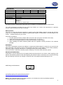
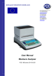
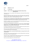
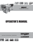
www.pce-industrial-needs.com
Tursdale Technical Services Ltd
Unit N12B
Tursdale Business Park
Co. Durham
DH6 5PG
United Kingdom
Phone: +44 ( 0 ) 191 377 3398
Fax: +44 ( 0 ) 191 377 3357
[email protected]
http://www.industrial-needs.com/
Instruction Manual
Manometer PCE-PXX
[email protected]
INTRODUCTION ..................................................................................................................... 3
CONVERSION ........................................................................................................................ 3
CONROLS AND INDICATORS ............................................................................................... 3
AUTO POWER OFF (SLEEP FUNCTION) .......................................................................... 4
MODE OPTIONS ................................................................................................................. 4
MAINTENANCE ...................................................................................................................... 5
CALIBRATION MODE......................................................................................................... 6
CALIBRATION POINT REFERENCE ................................................................................. 7
MANUAL ZERO SETTING .................................................................................................. 7
TROUBLESHOOTING......................................................................................................... 7
REPLACING THE BATTERY .............................................................................................. 7
OPERATING CONDITIONS ................................................................................................ 7
SPECIFICATION ................................................................................................................. 8
RS232 OUTPUT .................................................................................................................. 8
WARRANTY ............................................................................................................................ 8
RETURN AUTHORIZATION ............................................................................................... 8
2
[email protected]
Congratulations on your purchase of the Manometer! This instrument is portables battery operated pressure
measuring device.
The Manometer is ideal for HVAC/R technicians measuring pressure level, Medical equipment computer
peripherals, pneumatic Controls.
INTRODUCTION
•
•
•
•
•
The meter will display all LCD segments when it is first turned on for approx. 3 seconds. Though you
might have seen DATALOGGER, Y/M/D, REL, AVG ... these are not available for the meter. The meter
with data logger features named 8205D/821 5D/8280D/821 OOD. Please contact the store or the place
you purchased.
The LCD is divided into two distinct sections: One large (Primary) top screen and one smaller rightbottom bottom screens (relative Clock), The 2 display areas keep you constantly updated with the)
pressure measurements.
The Meter measures Gauge pressure-a measure of pressure in psi that is referenced to ambient
pressure and Differential pressure - a measure of the difference two pressures.
11 pressure units are selectable for Imperial and Metric in the different area: bar, mmHg, ozin², kgcm²,
psi, inH2, kPa, ftH2O|, inHg, cmH2O, mbar.
Please check the tubing is not leakage or damaged before using
CONVERSION
Manometer
PCE-P05
PCE-P15
PCE-P30
PCE-P50
PSI
5
15
30
100
Inch of
H2O
138
415
830
2768
mbar
kg/cm³
345
1034
2068
6895
0,35
1,05
2,10
7,03
CONROLS AND INDICATORS
1.
2.
3.
4.
5.
6.
7.
8.
9.
10.
11.
12.
13.
14.
15.
Primary Data Screen displays pressure value.
“-“: Minus pressure display.
MAX MIN: pressure recorded.
REC: starts recording mode and displays max./min. pressure recorded,
AVG: Average records (N/A).
DC: power in Jack.
RS232: output port.
H/M/S 88:88:88: displays data for Hour / Minute / Second.
: Pressure unit indication.
BAT: Battery low indicator.
DIF: Differential pressure mode.
“+”: Positive pressure home plug.
“-“: Negative pressure hose plug.
HOLD: Freezes pressure reading.
REL: Establish a relative zero for the primary screen information. (N/A)
3
[email protected]
Note: There
e are two co
onnecting me
etal lug 5mm
m, plastic lug
g 9.25mm fo
or different a
application pu
urpose . Ma
ake
sure which one
o you want before purcchasing the unit.
u
AUTO POW
WER OFF (SL
LEEP FUNCTION)
This instrum
ment will shut off automatically in apprrox. 20 minuttes for every power on.
For recordin
ng or operating over long
ger periods of
o time, you can disable the sleep m
mode by pres
ssing
a
and
simultan
neously before power on.
An “n” will appear
a
in the
e middle of th
he screen att which tinge
e you can rellease the
button. (See Fig. A) The
T
disable steep mode will be
b invalid aftter paper off..
MODE OPTIONS
r
with program cab
ble user selectable start-u
up mode.
Delete and replace
The display will default to
o the mode last used.
For your con
nvenience the setting use
ed during the
e last operation.
The followin
ng table listss the modess of operatio
on that can be invoked by
button indica
ated.
pressing
t
the
Turnss instrument on
o (Default setting)
s
and off.
o
Presss momentarilyy and relative
e clock startss in the lower right screen.
REC is displayed in the middlle deft of (Fig. B) other button
b
functions are lockked out exce
ept Power, Unit
U
and Backlight.
B
Presss momentarilyy again and the unit cyclles through MAX
M
(Fig. C) and man (F
Fig. D) and back
b
to curre
ent
pressu
ure; the reco
ord mode is displayed
d
on the LCD.
Presss and hold forr 3 seconds to
t turn off the
e normal mo
ode.
4
[email protected]
Presss momentarrily to freeze the pressure
e reading. (F
Fig. E)
Presss momenta
arily, DIF appears on to
op of the LC
CD and tile display indicates the re
elative zero re
(Relative zero ca
auses the va
alue of the dissplay to show
w as ''0,0'') -o
only the amo
ount of press
sure
chang
ge
will be indica
ated. Press momentarily
m
again and th
he unit return
ns to the norm
mal mode of pressure
differenttial
(see Fig. F).
P
A measure of the differencce between two
t
pressure
es, i.e. use d
differential prressure senssor
Differential Pressure:
to measure gauge presssure by 1e
eaving one process
p
connection ope
en to atmosp
phere and connecting
c
t
the
second senssor port to yo
our system.
Presss momentarily and the unit will cyccle through bar, mmHg, ozin², kgcm
m², psi, inH2
2, kPa, ftH2
2O,
inHg
g, cmH2O, mbar,
m
which in
ndicated on the
t bottom of
o the displayy (See Fig. G & H).
Presss momentarrily and the backlight
b
illum
minates for approx.
a
30 se
econds then turns off
Or press
p
momen
ntarily to decrease the fig
gure when ca
alibration is being
b
perform
med.
automatically.
NCE
MAINTENAN
•
•
•
The meter is calibrated in ho
ouse before shipping. To
o maintain th
he meter in tthe good con
ndition for usse,
reco
ommend to calibrate
c
the meter
m
after to
ong time usin
ng.
Whe
en properly maintained,
m
the meter will
w maintain an accuracyy specificatio
on to ensure
e your meterr is
perfforming at itss peak; sen
nd it to the factory
f
or a qualified instrument calibration facility for annu
ual
calib
bration.
Reccommend alw
ways to get zero
z
before measurement
m
t prefer to the zero setting procedure in page 10.
Cleaning:
p cloth and mild
m soap to clean
c
the casse of the Manometer do kcal use harrsh detergents or abrasivves
Use a damp
as these ma
ay mar the fin
nish or dama
age the unit'ss case with an adverse ch
hemical reacction.
5
[email protected]
CALIBRATION MODE
Calibration mode
m
is only applicable fo
or a standard
d Manomete
er calibrator or
o any qualified meter calibration facillity
for annual ca
alibration,
1. Firstt, please manually set the
e display to zero
z
(no pres
ssure applied
d to the conn
nector), referr to the Manu
ual
zero
o procedure.
2. Turn
n the meter off.
o
simultan
3. Presss
&
neously ''CA'' appears on
n the displayy, (See Fig. I) the meter enters to the
t
calib
bration mode
e, make surre the pressu
ure unit to be
b pointed under
u
the arrrow mark
is psi start
posiitive (+) pressure calibrattion
4. The meter has defaulted
d
as 80 psi calibra
ation point, the adjustable pressure rrange in from
m 78.0 to 82.0
0 if
calib
bration presssure source is not 80 psi , to increase the figure by pressing
key , or decrease the
t
figurre by pressin
ng
key to
o set calibrattion point as required.
key , ''SA'' and small '''CA” appearss on the disp
5. Save the calibra
ation point byy pressing
play (See Fig
g. J
) in 2 seconds , the
t meter au
uto-skip to the
e negative pressure (-) point
p
for next calibration mode.
m
6. Follo
ow the same
e procedure as
a step 4 forr the negative pressure calibration
c
po
oint by press
sing
ke
ey ,
the LCD now dissplays '' -80 ,0 '' and small ''CA'' (See Fig. K ), do the necesssary calibration figure reffer
to yo
our pressure
e standard if needed.
7. Again save the calibration
c
po
oint by presssing
ke
ey, ''SA'' and ''CA'' appea
ars in 2 seconds and then
n ''
a
in an
nother 2 seco
onds, the me
eter turns back to the norrmal mode (S
See Fig . L).
End'' and ''CA'' appears
s
by presss
key, i.e.
i no ''SA'' appeared, please check: (a) The calibration pres
ssure source
e is
If you can't save
between 75.0 and 85.0, or check (b)
( if you en
nter the righ
ht positive pressure (+) or negative pressure (--) .
If you want to
skip
t skip positivve (+) calibra
ation when entered
e
to the
e Calibration
n mode, press to
p to negative
e () calibration point.
Above calib
bration is an
n example fo
or model 82
2100, i.e. the pressure range is fro
om 0 to +10
00psi (Positiive
pressure) orr from 0 to -100 psi (Nega
ative pressurre).
6
[email protected]
CALIBRATION POINT REFERENCE
Model
psi-range
PCE-P05
0 ~ ±5
PCE-P15
0 ~ ±15
PCE-P30
0 ~ ±30
PCE-P50
0 ~ ±100
Calibration point
4,000
12,00
24,00
80,00
(±) Recommend
3,900 ~ 4,100
11,70 ~ 12,30
23,40 ~ 24,60
78,00 ~ 82,00
MANUAL ZERO SETTING
When you set the display to zero (no pressure applied to the connector), press button
for 2 seconds, now
the meter display ''0 .0.0.0'' from right to left and then disappear each ''0'' from left back to right, the LCD display
shows a normal mode.
TROUBLESHOOTING
•
•
•
•
•
•
•
•
Power on but no display. Check the batteries are in place and making good contact or correct polarity,
replace a new battery or attach optional AC adaptor for the weak battery caused.
BAT indication. Replace with a now battery when LCD display BAT at the middle bottom.
No Display. Make sure battery is not empty, if the display disappears, check sleep mode is active. Refer
to the Disable sleep mode function for a long time using the measurement. Or check the tubing is
connected to the meter tightly.
Err.1. For the pressure value exceed the maximum range, ''Err. 1'' appears on the display, p1ease
change the sensor, otherwise, the sensor will be hurt for going on the over range measurement.
Err.2. For the measurement pressure is less than minimum range, ''Err. 2'' will appear recommend to
change the sensor (meter).
Err.3. For operating the DIF function, the differential pressure value is larger than maximum display
digit, Err.3 appears on the display.
Err.4. When you set zero, make sure you have disconnected the tubing, no pressure applied to the
connector. Then if you see an Err.4 appears on the display, it means the sensor or meter damaged.
Return the unit to the store you purchased for repaired.
Err.4 will be also appeared while the tube or hose is connecting during setting zero mode.
E1OL or E2UL. When you see the errors while operating RS232 software, it means pressure source is
less or over than the range of the instrument.
REPLACING THE BATTERY
Replace your 9-volt battery when:
• The BAT icon appears on the right of the screen.
• The meter will not power on.
• Use of the back-light causes the BAT icon to appear.
Even if the battery was recently replaced check its voltage level if you get no response from your instrument.
To replace the battery:
1. Remove the tubing of the instrument.
2. Lay the instrument face-down on a clean, flat surface.
3. Remove the battery by screw driver and observe indicated polarity and close the cover after replacing
with a new battery.
Remove battery from instruments that you do not plan to use for a month or more.
Do not leave battery in instrument.
OPERATING CONDITIONS
•
•
•
•
•
•
Compensated temperature range: 0 – 50°C
Operating temperature 0 – 50°C (32 – 122°F)
Storage temperature range: -20 – 60°C
Operating Humidity Max. 80% RH
Power: One 9.0 volt battery
Exceeding Maximum pressure will cause permanent sensor damage.
7
[email protected]
SPECIFICATION
Range
Resolution
Accuracy
Dimension
Unit Weight
Response time
Data Format
PCE-P05
PCE-P15
PCE-P30
0 – 5 psi
0 – 15 psi
0 – 30 psi
0,003 psi
0,01 psi
0,02 psi
±0,3% of full scale at 25°C
72 x 182 x 30 mm
Approx. 220 gram (with battery)
0,5 seconds
Baud Rate: 2400 bit/sec
Data Bit: 8
Stop Bit: 1
P XXXXX. P -XXXXX (unit)
PCE-P50
0 – 100 psi
0,1 psi
The meter Pressure measurement instruments are not suitable for the absolute pressure measurement.
The meter instruments are fitted with two 4.8mm lugs. Before you connect the instruments to a pressure
sources, check carefully the security of ail fitting.
RS232 OUTPUT
The meter can link both personal computer to capture on-line dates display pressure records with real-time
output, you can retrieve file save the datas for operating data analysis, records statistic, multi-files display in the
screen,....versatile functions for your choice.
Connection procedures:
1. Plug the optional accessory RS232 cable onto the DC jack port (at the right side of the meter)
2. Insert the D-sub 9P type connector onto computer's Com 1 or 2 port or…
3. Start to set up RS232 software by inserting the CD-ROM or Floppy diskette.
4. When installing the RS232 software please follow the operation manual procedure in the software
package.
WARRANTY
The meter is warranted to be free from defects in material and workmanship for a period of one year from the
date of purchase. This warranty covers normal operation and does not cover battery, misuse, abuse, alteration,
tampering, neglect, improper maintenance, or damage resulting from leaking batteries.
Proof of purchase is required for warranty repairs. Warranty is void if the meter has been opened.
RETURN AUTHORIZATION
Authorization must be obtained from the supplier before returning items for any reason, When requiring a RA
(Return Authorization) please include data regarding the defective reason, the meters are to be returned along
with good packing to prevent any damage in shipment and insured against possible damage or loss.
WEEE-Reg.-Nr.DE64249495
In this direction will find a vision of the measurement technique:
http://www.industrial-needs.com/measuring-instruments.htm
NOTE: "This instrument doesn’t have ATEX protection, so it should not be used in potentially explosive
atmospheres (powder, flammable gases)."
8