1
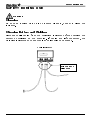
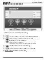
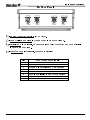
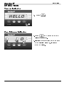
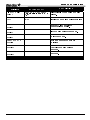
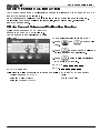
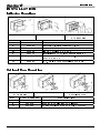
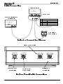
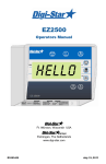
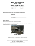
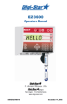
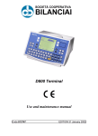
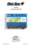
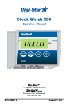
EZ400
Operators Manual
HELLO
Ft. Atkinson, Wisconsin USA
Panningen, The Netherlands
www.digi-star.com
D3655-US REV E
February 09, 2010
EZ400 User’s Manual
D3655-US Rev E
TABLE OF CONTENTS
Table of Contents
TECHNICAL SPECIFICATIONS ..................................................................... 1
SAFETY DURING USE ................................................................................... 2
Cleaning ....................................................................................................... 2
Charging Battery and Welding ..................................................................... 2
INDICATOR OVERVIEW ................................................................................ 3
OPERATION ................................................................................................... 5
Turn on Indicator .......................................................................................... 5
Zero Balance Indicator ................................................................................. 5
Tare and Net/Gross ..................................................................................... 6
Store Data to DDL........................................................................................ 8
Printing Gross Weights ................................................................................ 8
Print Formats ............................................................................................... 9
Changing Indicator ID Name & Clearing Accumulated Weight ................. 10
Turning Off the Indicator ............................................................................ 10
WEIGH METHODS ....................................................................................... 11
General Weigh Method #1 ......................................................................... 11
Slow Weigh Method #2 .............................................................................. 11
Fast Weigh Method #3 ............................................................................... 11
Lock-on Weigh Method #4 ......................................................................... 11
WEIGHING ERRORS ................................................................................... 12
Over-Capacity Limit (OVRCAP)...................................................................... 12
Over Range (+RANGE) .................................................................................. 12
Under Range (-RANGE)................................................................................. 12
Low Battery Indication (LO BAT) ................................................................... 12
RUN SELF TEST .......................................................................................... 12
MENUS AND CALIBRATION ........................................................................ 13
Changing Options Using Long Form Setup ............................................... 13
SHORT FORM CALIBRATION ..................................................................... 17
Obtain Current Set-up and Calibration Number ........................................ 17
Calibrating Scale For Maximum Accuracy ................................................. 18
Determining New Setup and Calibration Numbers .................................... 18
Enter A New Setup And Calibration Number ............................................. 19
INSTALLATION ............................................................................................. 20
Indicator Mounting ..................................................................................... 20
Optional Ram Mounting ............................................................................. 20
Cable Connection ...................................................................................... 21
Indicator Connection Diagram ................................................................... 21
Bottom Panel Cable Connections .............................................................. 21
Connect Load Cells to J-Box ..................................................................... 22
Load Cell Direction..................................................................................... 22
D3655-US Rev E
EZ400 User’s Manual
Table of Contents
Indicator Calibration ................................................................................... 22
OPTIONAL EQUIPMENT .............................................................................. 23
Data Transfer Options................................................................................ 23
Remote Indicators ...................................................................................... 23
TROUBLESHOOTING .................................................................................. 24
All rights reserved. Reproduction of any part of this manual in any form whatsoever without Digi-Star’s express written permission is
forbidden. The contents of this manual are subject to change without notice. All efforts have been made to assure the accuracy of
the contents of this manual. However, should any errors be detected, Digi-Star would greatly appreciate being informed of them.
The above notwithstanding, Digi-Star can assume no responsibility for errors in this manual or their consequence.
© Copyright! 2009 Digi-Star, Fort Atkinson (U.S.A.).
EZ400 User’s Manual
D3655-US Rev E
TECHNICAL SPECIFICATIONS
Technical Specifications
SIZE
7.33” long x 5.25” high x 3.38” wide (186mm x
133mm x 85mm)
DISPLAY RESOLUTION
.01, .02, .05, .1, .2, .5, 1, 2, 5, 10, 20, 50, 100
WEIGHT
2 lbs (.91 Kg)
DISPLAY UPDATE RATE
Selectable: 1, 2, 3, 4 times/sec.
HELP MESSAGES
Context sensitive help messages in 10
languages
Long messages are scrolled
MAX. DISPLAY RESOLUTION
Adjustable to 40,000 counts max.
TRANSDUCER EXCITATION
8 volts D.C. Nominal
Capable of driving eight 350 Ohms transducers
Short circuit proof
ATC
Auto Temperature Compensation of the internal
circuitry for high accuracy weighing
measurements
TRANSDUCER SIGNAL
Compatible with transducers having full scale
indicator transfer characteristics greater than
0.25 mv/v
“AUTO RANGE”
(Selectable) To increase display counts
at weight values of 300 and 600 display counts.
CONNECTOR
AMP plastic weather resistant circular
connector. Gold contacts.
POWER REQUIREMENTS
10.5 to 16.0 V.D.C.
160 mA nominal with four 350Ω L.C.
ZERO TRACKING
Selectable, On/Off
SPAN ACCURACY
±(.1% + .005%/ °F) or (.1% + 0.009% °C) full scale ± 1
output count
MOTION DETECTION
Selectable, On/Off
ZERO ACCURACY
(.005%/ °F.) or (0.009% °C) full scale ±1 output count
for 0.5 mv/v transducer
ENVIRONMENTAL ENCLOSURE
IP65, IEC 529
WEIGH ALGORITHM
4 internally selectable digital filters to optimize
performance
(General, Slow, Fast and Lock-on)
NON-VOLATILE MEMORY
EEPROM for balance
OPERATING TEMP
-29°C to 60°C
-20°F to 140°F
SET UP AND CALIBRATION
Via front panel
GROSS RANGE
999,999 max.display
LOW BATTERY WARNING
Enabled at 10.5V nominal
POUND/KILOGRAM
Selectable
DISPLAY
STD EZ 6 Digit LCD 1.0. high
D3655-US Rev E
EZ400 User’s Manual
1
SAFETY DURING USE
Safety During Use
Caution
Cleaning
Do not use running water (high pressure cleaners, hoses) to clean the
indicator.
Charging Battery and Welding
Disconnect all cables from the weighing indicator before charging the
battery or welding on the machine. If cables are left connected, the
weighing indicator and connected load cells could be damaged.
Scale Indicator
Disconnect
all cords
2
EZ400 User’s Manual
D3655-US Rev E
Indicator Overview
INDICATOR OVERVIEW
5
1
2
3
4
Note: See page 20 for installation instructions.
1
– press and hold for 3 seconds to zero balance indicator.
2
– temporary zero (Net Mode) (Standard EZ400).
- Optional: (EZ400 with serial port)
temporary zero (Net Mode)
printer records to memory or prints displayed weight
3
– toggles between Net and Gross weights.
4
– turns indicator on/off. Press while on runs self test.
5
Display Window – Displays current actions.
D3655-US Rev E
EZ400 User’s Manual
3
Indicator Overview
Bottom Panel
6
9
7
8
6 - Power Cord Connection – +12 VDC.
7 -Load Cell Connection – Connect cable from the J-Box.
8 -Serial/J905 – Optional, to communicate with computer and other digital
Input/Output devices.
9
- Remote Port – Optional, for remote display
Pin
1
2
3
4
5
6
7
8
4
J905 Connector Signals
+5VDC
Com #1 Out (Tx) - Computer
Com #1 In (Rx) - DDL & Computer
Com #2 Out (Tx) - Printer
+12 VDC
Gnd – Available for any Com device
Com #2 In (Rx)
Ground
EZ400 User’s Manual
D3655-US Rev E
Operation
OPERATION
Turn on Indicator
1.
HELLO
Press
.
1
Zero Balance Indicator
1. Press
1
1
0
2
for 3 seconds to zero
balance indicator.
2. Flashing arrow points to gross next
to the display window, indicator
ready to weigh.
D3655-US Rev E
EZ400 User’s Manual
5
Operation
Tare and Net/Gross
Tare is a temporary zero (Net Weight)
to display total weight (Gross Weight)
Press
.
4000
1. Weight displayed, press
zero weight.
sets
1
0
2. Pressing
displays zero weight
and flashing arrow on side of
display points to NET.
2
3
6
3. Add more weight.
300
EZ400 User’s Manual
D3655-US Rev E
Operation
4. To know total of original weight of
4000 pounds plus added 300
pounds, press
to show 4300
pounds, flashing arrow points
GROSS.
4300
4
5. Press
300 pounds displayed
flashing arrow points NET.
300
5
D3655-US Rev E
EZ400 User’s Manual
7
Operation
Store Data to DDL
(Serial Option Only)
1. Connect the DDL to the SERIAL
port on the bottom panel. See page
4.
2. Press and hold
to save print
data to the DDL.
2
Printing Gross Weights
Optional serial port must be
installed for printing.
Note:
1
8
1. Press and hold
3 seconds to
send displayed weight to serial port.
Each time this command is executed
the value displayed is added to the
“PRTACC” which is the accumulated
weight. Weight is accumulated until
cleared.
EZ400 User’s Manual
D3655-US Rev E
Operation
Print Formats
Three print formats are available to output PRTACC value and SCALE ID to DDL
or printer.
PRTAC1:
FIELD ID, 4856, GR, 274575, PA, 05FE08, I:44P
PRTAC2:
FIELD ID, 05FE08, I:44P
4856, GR, 274575, PA
Includes following information:
• Scale ID (SCALID)
• Weight
• Weight Tag (Net, Gross, Load/Unload)
• Accumulated Weight
• Print Accumulator Tag
• Date and Time
FIELD3, 5977, LB, ,GR, 3097I9,PA,05FE08, 4:42P
PRTAC3:
Includes above and adds “Unit of Measure” and “Lock-On Status” (for
animal weighing).
See “Setting Options” (page 13) to change print format (PRTFMT).
D3655-US Rev E
EZ400 User’s Manual
9
Operation
Changing Indicator ID Name
& Clearing Accumulated
Weight
5
SCALID
2
1 2
3 4
1. Press and hold
3 seconds.
SCALID is displayed followed by
current ID name.
2. Use
and
to enter new
Scale ID.
3. Press
to view accumulated
weight.
4. Press
to resume weighing.
Or
5. Press
to clear accumulated
weight total.
Turning Off the Indicator
bye
1. Press
until “BYE” is displayed.
1
10
EZ400 User’s Manual
D3655-US Rev E
Weigh Methods
WEIGH METHODS
Select weigh method #1 for general weighing.
General Weigh Method #1
All purpose weigh method for stable loads.
Slow Weigh Method #2
Higher accuracy for weighing stable loads.
Fast Weigh Method #3
Determines new weight quickly when weighing stable loads.
Lock-on Weigh Method #4
Weighing active animals and displays stable accurate weight. Set to “OFF” for
weighing stable weights. Lock-On sensitivity can be adjusted using “LOCKON”
menu.
Once weight displayed, scale “Locks-On” to weight. Weight does not change,
even if motion never stops. Small ‘L’ appears on left side of the display
indicating weight “Locked-On.” Animal’s weight must be greater than 2.5% of
scales “capacity” weight before system “Lock-On.”
Break lock, 50% of displayed weight added or removed from scale. “LockedOn” weight can be “rechecked” by pressing . . This breaks “lock” and scale
recalculates weight.
D3655-US Rev E
EZ400 User’s Manual
11
Weighing Errors
WEIGHING ERRORS
Over-Capacity Limit (OVRCAP)
The display shows the message "OVRCAP" if the weight on the scale system
exceeds the capacity limit. The capacity value is entered in SETUP to warn of
overloading the scale system.
Over Range (+RANGE)
The display shows the message "+RANGE" if the weight on the scale system
exceeds the maximum weight measurable by the scale system. The over
range value is always the system’s maximum A/D counts multiplied by the
scaling factor. The actual weight at which over range occurs depends on the
calibration, zero, and display count size.
Under Range (-RANGE)
The display shows the message "-RANGE" if the weight on the scale system is
less than the minimum weight measurable by the scale system. The under
range value is always the system’s minimum A/D counts multiplied by the
scaling factor. The actual weight at which under range occurs will depend on
the; calibration, zero, and display count size.
Low Battery Indication (LO BAT)
If the supply voltage drops below the (10.5 Volts), the message RECHARGE
BATTERY - TURNING OFF” and LO BAT” will periodically show on the display to alert
the operator of the low battery condition.
“
“
RUN SELF TEST
1
12
1. Press
then
during
normal system operation to start
self-test.
EZ400 User’s Manual
D3655-US Rev E
MENUS AND CALIBRATION
Menus and Calibration
The Indicator has optional settings that allow flexibility in the way that the scale
is used and data is collected.
Changing Options Using Long Form Setup
Enter Long Form Setup by holding
and
Press
to select menu 1, 2, 3 or 4.
for three seconds.
Press
to advance to desired parameter.
Press
to select proper setting.
Press
to save setting and advance to next parameter.
Hold
and press
to return to indicator operation.
Default settings from the factory vary with options and due to customer
preferences.
SETTING
[display]
OPTIONS [displayed]
BOLD=DEFAULT
DESCRIPTION
MENU 1. BASIC FEATURES IN MOST INDICATORS
LANGUAGE
(langag)
DISPLAY RATE
(0 rate)
ZERO TRACK
(ztrack)
English
Dutch
French
German
Italian
Portuguese
Spanish
Danish
Hungarian
Spanish
[ENGLSH)
[NEDERL]
[FRANCS]
[DEUTSH]
(ITAL]
(PORT]
(ESPAN]
(DANSK]
(MAGYAR]
(VESTA]
Select language to be displayed.
I,2,3,4
Update display times per second.
ON/OFF
If ON -zero track adjust balance for
buildup of snow & mud.
WEIGH METHOD
I=General,
(W mthd)
2=Fast,
3=Slow,
Select weigh method
4=Lock-On
D3655-US Rev E
EZ400 User’s Manual
13
Menus and Calibration
SETTING
[display]
LOCK-ON
(
OPTIONS [displayed]
BOLD=DEFAULT
I-7 , 8, 9
LOCKON)
SCALE ID SETUP
(scalid)
LOCK-N-HOLD
(
LKNHLD)
(
AUTOFF)
(
LSTORE)
(
LSSEND)
AUTO OFF
NEW EZ
On/OFF
I5, 30, 45, 60,
OFF
LOCK-ON-STORE
LOCK-ON-STORE
SEND
1 PRESS ZERO
DESCRIPTION
Use the lowest setting that still
allows the system to lock on
consistently. A low value allows the
system to be more sensitive to
animal motion. A high value allows
the scale to lock on faster.
Identity of scale (truck id or Mixer
number).
Weight is held until next animal is
weighed.
Indicator automatically shut OFF
after specified time of inactivity.
For animal weighing only.
For animal weighing only.
If ON -press and hold Zero key to
Zero/Balance scale.
MENU 2. CLOCK, PRINTER, COMMUNICATIONS & ESTIMATED
WEIGHT FEATURES
TIME FORMAT
24 HR
Select time format -AM/PM or 24
(time f)
hour
AM/PM
(I zero)
1 TIME
(time)
DATE FORMAT
(date f)
DATE
(date)
TARE AUTO
PRINT
ON/OFF
XX:XX:XX
1-mm-dd
2-mm/dd/yy
3-mm/dd/yyyy
4-dd-mm
5-dd/mm/yy
6-dd/mm/yyyy
7-ddmoyy
8-ddmoyyyy.
Enter XXXXXX
(Il prt)
14
Select date format
Select key changes date -function
key chooses mm/dd/yy .
ON/OFF
If ON -tare auto-prints displayed
weight.
ON/OFF
If ON -indicator data prints on one
line.
(tareap)
ONE LINE PRINT
Select key changes time, function
key chooses hh:mm:ss.
EZ400 User’s Manual
D3655-US Rev E
Menus and Calibration
SETTING
[display]
(
SCOREM)
AUTO PRINT
(aprint)
(COM IN)
OPTIONS [displayed]
BOLD=DEFAULT
I,2,3,4,5,6,
DOWNLD,
EZ CMD, EZ2CMD
AUTO
(prtfmt)
WTONLY
DOWNLD
DT+TM
ID+TM
IDWTTM
ANIMAL
3200-A
3200-B
32-TMR
DATCHI
FDINFO
WTRCTM
EIDINF
EID
EIDVID
PRTAC2
PRTAC3
(CI DLY)
OFF, .I0, .25, .50, .75, I-5
C2 DLY)
OFF, .I0, .25, .50, .75, I-5
(prtacc)
(tarprt)
ESTIMATED
WEIGHT
Select alternate & comma (CSV)
formats.
PRTAC1
(zerout)
(
Select scoreboard output mode 1/sec 2-2/sec 3-3/sec 4-every
conversion 5-display rate 6-display
weight change 7-send status 1/sec,
8-send status1/5sec, 9-Reserved &
I0-send EID 1/2 sec.
If ON -pressing keys auto-prints
weight values.
Com port interface selections
DOWNLD for Data Down Loader,
EZ CMD = Original EZ Commands,
EZ2CMD = EZII Escape
Commands.
I
ON/OFF
PRINT FORMAT
DESCRIPTION
Choose the number of seconds
the printer will delay before
advancing to the next print line.
Choose the number of seconds
the printer will delay before
advancing to the next print line.
Tare
Allows operator to adjust Gross
weight of scale by changing the
zero/balance.
ESTWT
MENU 3. SCALE CALIBRATION SETTINGS
DISPLAY COUNT .0I,.02,.05,.I,.2,.5,I,2,5,I0,20, Count set too small, readings
unstable and indicator not accurate
50,I00
COUNT
AUTO-RANGE
Scale increases display count size
ON/OFF
for weights over 300 again at 600
ARANGE
lbs/kgs.
(
)
(
)
(
0,I,2,3,4,5,6,7,8,9
)
D3655-US Rev E
EZ400 User’s Manual
15
SETTING
[display]
DISPLAY UNIT
OPTIONS [displayed]
BOLD=DEFAULT
Menus and Calibration
DESCRIPTION
(lb-kg)
.0I,.02,.05,.I,.2,.5,I,2,5,I0,20,
50,I00
Select display count size of weigh
values.
(cap)
LB/KG
Display pounds -lb or kilograms -kg
CAPACITY
WM1 ADJUST 1
(wmaI-I)
WM1 ADJUST 2
(wmaI-2)
WM1 ADJUST 3
(wmaI-3)
WM2 ADJUST 1
(wma2-I)
WM2 ADJUST 2
(wma2-2)
WM2 ADJUST 3
(wma2-3)
Enter MAXIMUM weight
measurable on scale.
0=OFF Use values less than WMA
1-1 for quick weight response.
Enter weight to activate quick
weight response.
Increase number to smooth
weighing
0=OFF Use values less than
WMA2-1 for quick weight
response.
Enter weight activate quick weight
response.
MENU 4 – NOT USED
16
EZ400 User’s Manual
D3655-US Rev E
SHORT FORM CALIBRATION
Short Form Calibration
The Short Form Setup & Calibration procedure allows you to change “SETUP”
and “CAL” numbers of indicator.
Do not attempt to calibrate scale if indicator is not reading stable weights.
Calibration procedure will not fix instability, inconsistencies, or flashing
"RANGE" messages.
Obtain Current Set-up and Calibration Number
Write down current SETUP and CAL
numbers of your EZ 400 indicator.
These numbers are displayed during
Self Test.
To run self test with indicator ON:
1. Press
then
to start Self
Test.
1
2. Press
to “pause” the Self-Test
while numbers are displayed.
3. Press
again to allow self-test
to complete normally.
SETUP # _______________
CAL # ________________
SETUP NUMBER
Following is a list of functions that are controlled by the “SETUP” number:
Weigh Method (
)
Gain
Display Units (
)
Scale Capacity
Display Counts (
)
3
2
1
W MTHD
LB-KG
COUNT
D3655-US Rev E
EZ400 User’s Manual
17
Short Form Calibration
Calibrating Scale For Maximum Accuracy
To accurately calibrate scale, you need a large amount of weight that
has a known value. For best results you should have at least as much weight
as largest load you plan to weigh.
Note:
Determining New Setup and
Calibration Numbers
1. Press
to Zero-Balance. See
page 5.
2. Put KNOWN WEIGHT on scale
platform and write down WEIGHT
DISPLAY.
Perform following equation to find
ACCURATE CAL #.
1
The setup number does not change.
18
EZ400 User’s Manual
D3655-US Rev E
Short Form Calibration
Enter A New Setup And
Calibration Number
1
4
3
1
1. Press and hold
then press
for 3 seconds to enter short
form calibration.
2. The display will flash “SETUP” and
then display the 6-digit setup
number with the right digit
flashing.
3. Press
several times to
increment digit to it proper value.
4. Press
to advance digit left.
Repeat steps 3 and 4 for each digit as
required.
7 5
D3655-US Rev E
5. Press
to enter new setup
number and display calibration
number.
6. Repeat steps 3 and 4 to modify
the calibration number.
7. Press
to enter new
calibration number and display will
go back to normal.
8. Verify the accuracy of scale.
EZ400 User’s Manual
19
Installation
INSTALLATION
Indicator Mounting
RAIL MOUNT
KEY
A
B
C
D
E
F
G
WING MOUNT
WEDGE MOUNT
STANDARD
PART NUMBER
DESCRIPTION
403769
BRACKET – STR TOP MOUNT
403980
BRACKET – ROBO MOUNTING
403770
BRACKET – WING MOUNT
405069
U-BOLT, 1/4-20 X 3.25 ZP
403771
MODIFIED PLASTIC WEDGE MOUNT
405124
WEDGE MOUNT BRACKET, INCLUDES UBOLTS & NUTS
405084
NUT, 1/4-20 TOP LOCKING FLANGE
Optional Ram Mounting
RAM MOUNT
U-BOLT BASE
TWIST LOCK
STANDARD
SUCTION CUP
KEY PART NUMBER
DESCRIPTION
A
403180
RAM MOUNT
B
403179
MOUNT BASE-1" BALL U-BOLT
C
404230
RAM SUCTION CUP W/TWIST LOCK
20
EZ400 User’s Manual
D3655-US Rev E
Installation
Cable Connection
Scale Indicator
Power Cord
Remote Indicator
(Optional)
Pin To 12VDC Power Supply
1 Red
+Terminal
2 Black
-Terminal
3 Orange Alarm Out
4 Blue Remote Input
See J-Box
Connections
Indicator Connection Diagram
J-Box Connection
Remote Port
(Optional)
Power Cord
Connection
Serial/J905
(Optional)
Bottom Panel Cable Connections
D3655-US Rev E
EZ400 User’s Manual
21
Installation
Connect Load Cells to J-Box
Connect load cell
wires to terminal
blocks. See Wire
Color Key
J-Box Illustrated for 4
Load Cell Installation
Wire Color Key
Color
Description
1
White
Signal +
2
Green
Signal -
3
Red
Excitation +
4
Black
Excitation -
5
Shield
Shield
Tighten Nuts
J-Box Cable
Load Cell Cable
Connect to Indicator
bottom Panel.
J-Box Connections
Load Cell Direction
Observe direction of arrow when installing load cell.
Indicator Calibration
If you connect an indicator to a different weighing implement, the calibration
and setup number may need to change. Refer to calibration procedures (see
pages 17-19) or contact your Digi-Star representative for assistance.
22
EZ400 User’s Manual
D3655-US Rev E
Optional Equipment
OPTIONAL EQUIPMENT
Data Transfer Options
Kit Data Down Loader
Allows transfer of data from indicator
to PC. (Optional Serial/J905 port must
already be installed in indicator)
Remote Indicators
RD440 small remote display
RD2400V backlit remote display with
1.7” high numbers
RD2400V backlit remote display
w/transmitter and installed receiver
RD4000 remote display
D3655-US Rev E
EZ400 User’s Manual
23
Troubleshooting
TROUBLESHOOTING
FLOW CHART
START
YES
Is the reading on the
Indicator stable?
Does the indicator come on?
If your display is unstable, or
flashes “±RANGE” disconnect
the j-box cord from Indicator.
Is display still unstable?
NO
YES
Put your weight on each
NO
load cell. Does the indicator
respond to your weight?
Check all J-Box
and Load Cell
YES
cables for cuts
or pinched/flat
spots.
Are the readings
all positive? If not
Load Cell is
upside down.
Does the scale weigh you
approx. the same over all
Load Cells? (Weight will
not be accurate)
: Take them
apart and clean connections.
(Rust or paint should be wire
brushed.) Then reconnect and
tighten securely.
Replace battery
(weak battery may test good if
tested with no load on battery)
Make sure
red wire is connected to (+)
positive side and black wire is
connected to (-) negative side.
When using a multimeter to
check for voltage, measure
between pin 1 (pos) and pin 2
(neg). Meter should read
between 10.5 and 14.5 volts
DC if using a tractor power
cord, black wire is positive and
white wire is negative.
Try another
Indicator. (Even a different
model or set-up should come
on.)
Poor Connection
YES
Bad Battery:
Bad Power Cord:
Your Indicator is probably
defective. Try another
Indicator to verify.
Be aware of electrical
interference that might
affect Indicator, such as
mobile phones, CB
radios, radio towers,
electrical motors, etc.
Make sure Load Cell
cables are not attached to
hydraulic lines or
reservoir.
Note:
NO
Bad Indicator:
Remove the cover from your J-Box
YES
Is there moisture inside the box?
Your Indicator is probably not set-up
and calibrated correctly. Check the
decal on the bottom of Indicator. It
shows what type of Load Cells the
Indicator was calibrated to. By
pressing the on key while the
Indicator is already on, you will get
the Indicator’s “Set-up” and “Cal”
numbers. See if they compare to the
set-up and calibration numbers on
the Indicator. Contact Dealer for
further information.
Fix or replace the J-Box
NO
YES
NO
Look for loose connections.
Watch your Indicator display
while moving the wires and
pressing on the circuit board
inside the J-Box. You will see
if there is a loose connection
or bad solder joint.
YES
Dry out your J-Box (use a
hairdryer). Check cable
strain reliefs for tightness.
Cables have drip loops. Is
lid gasket damaged?
Did the J-Box have a bad
connection or loose wire?
NO
See next Page
24
EZ400 User’s Manual
D3655-US Rev E
Troubleshooting
FLOW CHART
Continued
1. Disconnect all the Load Cell
wires from the terminal blocks
inside the J-Box (leave the
Indicator on while connecting
and disconnecting the wires, it
will not damage Load Cells or
Indicator if wires are shorted
during this step). Is reading on
Indicator stable?
YES
Hook up the Load Cells to the J-Box one at
a time (only one Load Cell connected at a time).
This will get a reading for each Load Cell. While
performing this test, watch for any other
symptoms such as erratic/unstable display.
Indicator flashing “±RANGE”, negative reading,
etc. If the Indicator reading should ever appear
abnormal with any Load Cell connected then it is
probably bad.
Note:
NO
Replace J-Box
(be aware of electrical
interference that might affect
your scale such as: mobile
phones, CB radios, radio
towers, electric motors, etc.).
3. Connect one Load Cell back into one of the
terminals in the J-Box. (The reading you get for
each Load Cell is dependent on the size and type
of each Load Cell and how much weight is over
each Load Cell. In general, the number should be
positive and stable.)
4. Record the Indicator reading with
the Load Cell connected.
5. Stand or hang your weight over the connected
Load Cell. Record how much the weight
increased with your weight over the Load Cell. (A
scale with only one Load Cell will weigh heavy.)
7. Repeat step 6 for the remaining Load Cells.
Remember to record your readings.
Do not expect the Load Cells to give the same
reading. It is common for Load Cells to have
readings that vary by hundreds, even thousands.
Especially when one is carrying more weight.
D3655-US Rev E
2. Zero balance the Indicator.
(Press “NET/GROSS” then
“ZERO”). Indicator should display
“0”.
If the scale responded to your weight,
that’s verification on the J-Box is OK. If the
scale did not respond, either that Load Cell is
bad or the J-Box is bad. Try the other Load
Cells. If the Indicator still shows no response,
the J-Box is bad. (Replace J-Box)
Note:
6. Disconnect the first Load Cell and reconnect
a second one. Record the Indicator reading.
Stand or hang your weight over the connected
Load Cell. Record how much the weight
increased.
8. Bad Load Cells will have a reading that is
either unstable, makes the indicator flash
“±RANGE” or is more than three times greater
or less than the average of the others. Also the
readings of your weight over each Load Cell
should be similar. (Probably 4 times your actual
weight). Any differences could be an indication
of a bad Load Cell or a structural problem.
EZ400 User’s Manual
25