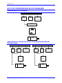
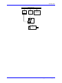
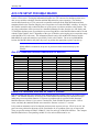
1
^1 USER MANUAL
^2 Accessory 57E
^3 Yaskawa & Mitsubishi Abs. Enc. Con. Board
^4 3Ax-603484-xUxx
^5 November 16, 2007
Single Source Machine Control
Power // Flexibility // Ease of Use
21314 Lassen Street Chatsworth, CA 91311 // Tel. (818) 998-2095 Fax. (818) 998-7807 // www.deltatau.com
Copyright Information
© 2007 Delta Tau Data Systems, Inc. All rights reserved.
This document is furnished for the customers of Delta Tau Data Systems, Inc. Other uses are
unauthorized without written permission of Delta Tau Data Systems, Inc. Information contained
in this manual may be updated from time-to-time due to product improvements, etc., and may not
conform in every respect to former issues.
To report errors or inconsistencies, call or email:
Delta Tau Data Systems, Inc. Technical Support
Phone: (818) 717-5656
Fax: (818) 998-7807
Email: [email protected]
Website: http://www.deltatau.com
Operating Conditions
All Delta Tau Data Systems, Inc. motion controller products, accessories, and amplifiers contain
static sensitive components that can be damaged by incorrect handling. When installing or
handling Delta Tau Data Systems, Inc. products, avoid contact with highly insulated materials.
Only qualified personnel should be allowed to handle this equipment.
In the case of industrial applications, we expect our products to be protected from hazardous or
conductive materials and/or environments that could cause harm to the controller by damaging
components or causing electrical shorts. When our products are used in an industrial
environment, install them into an industrial electrical cabinet or industrial PC to protect them
from excessive or corrosive moisture, abnormal ambient temperatures, and conductive materials.
If Delta Tau Data Systems, Inc. products are directly exposed to hazardous or conductive
materials and/or environments, we cannot guarantee their operation.
REVISION HISTORY
REV.
1
DESCRIPTION
ADDED ACC-57E DB15 CONNECTOR OPTION P. 28-29
DATE
11/16/07
CHG
APPVD
CP
S. MILICI
Accessory 57E
Table of Contents
INTRODUCTION .......................................................................................................................................................1
Options ......................................................................................................................................................................1
BOARD LAYOUT.......................................................................................................................................................3
Acc-57E - Yaskawa DB15 Option ............................................................................................................................3
Acc-57E - Yaskawa Terminal Block Option............................................................................................................3
Acc-57E - Mitsubishi Terminal Block Option ..........................................................................................................4
HARDWARE SETTINGS ..........................................................................................................................................5
Address Select DIP Switch S2 ..................................................................................................................................5
Turbo PMAC 3U Switch Settings..........................................................................................................................6
MACRO Station Switch Settings ...........................................................................................................................6
JUMPERS ....................................................................................................................................................................7
E-Point Jumpers ........................................................................................................................................................7
JP- Jumpers ...............................................................................................................................................................7
Connector Descriptions .............................................................................................................................................7
TB1 and TB2.........................................................................................................................................................7
J1 and J2...............................................................................................................................................................7
J3 and J4...............................................................................................................................................................7
J6 ..........................................................................................................................................................................7
J7 ..........................................................................................................................................................................7
P1..........................................................................................................................................................................7
Hardware Address Limitations..................................................................................................................................8
UMAC Card Types ...............................................................................................................................................8
Chip Select Addresses...........................................................................................................................................8
Addressing Conflicts .............................................................................................................................................8
Type A and Type B Example 1: Acc-11E and Acc-57E .......................................................................................8
Type A and Type B Example 2: Acc-11E and Acc-65E ........................................................................................8
ACC-57E THEORY OF OPERATION.....................................................................................................................9
UMAC TURBO I-VARIABLE SETUP FOR POWER ON POSITION ..............................................................11
Ixx10 – Motor xx Power-On Position Address .......................................................................................................11
Ixx95 - Motor xx Power-On Servo Position Format ...............................................................................................11
Ixx98 - Motor xx Resolver Third Gear Ratio (Yaskawa Only) for Turbo...............................................................11
Ixx99 - Motor xx Second Resolver Gear Ratio (Yaskawa Encoder only) for Turbo ..............................................12
I8x - Motor xx Resolver Third Gear Ratio (Yaskawa only) for non-Turbo ............................................................12
I9x- Motor xx Second Resolver Gear Ratio (Yaskawa Encoder only) for non-Turbo ............................................12
Example: Turbo UMAC Yaskawa Absolute Encoder Setup...............................................................................12
Example: Turbo UMAC Mitsubishi Absolute Encoder Setup .............................................................................13
POWER ON PHASING WITH ACC-57E ..............................................................................................................15
Ixx81 .......................................................................................................................................................................15
Ixx91 .......................................................................................................................................................................15
Ixx75 .......................................................................................................................................................................15
Ixx80 .......................................................................................................................................................................16
ACC-57E CONFIGURATION BLOCK DIAGRAMS ..........................................................................................17
Yaskawa Servo Pack Diagram ................................................................................................................................17
Yaskawa Generic Absolute Encoder Setup Mitsubishi Absolute Encoder Setup ...................................................17
ACC-57E SETUP FOR UMAC MACRO ...............................................................................................................19
Acc-57E Absolute Encoder Addresses for MACRO...............................................................................................19
Power-On Feedback Address for PMAC2 Ultralite ................................................................................................19
Absolute Position for Ultralite............................................................................................................................20
Absolute Position for Turbo Ultralite .................................................................................................................20
MACRO Absolute Position Setup...........................................................................................................................20
Table of Contents
i
Accessory 57E
MACRO MI11x Parallel Word Example ............................................................................................................21
Example: UMAC MACRO Yaskawa Absolute Encoder Setup............................................................................21
Example: UMAC MACRO Mitsubishi Absolute Encoder Setup ........................................................................22
CONNECTOR PINOUTS.........................................................................................................................................23
J1 – Yaskawa Sigma Series Encoder Input .............................................................................................................23
J2 - Yaskawa Sigma Series Encoder Input..............................................................................................................24
J3 - Mitsubishi
RS422 Input..............................................................................................................................25
J4 – Mitsubishi
RS422 Input..............................................................................................................................25
ACC-57E TERMINAL BLOCKS ............................................................................................................................27
Connector TB1 Top - Encoder 1 .............................................................................................................................27
Connector TB2 Top - Encoder 2 .............................................................................................................................27
ACC-57E DB15 CONNECTOR OPTION ..............................................................................................................28
Connector J1 Top - Encoder 1.................................................................................................................................28
Connector J2 Top - Encoder 2.................................................................................................................................29
SERVOPACK 1CN TERMINAL DESCRIPTION ................................................................................................30
SCHEMATICS ..........................................................................................................................................................32
ii
Table of Contents
Accessory 57E
INTRODUCTION
UMAC’s Acc-57E allows a UMAC interface to the Yaskawa or Mitsubishi absolute encoder. The Acc57E is part of the UMAC or MACRO Pack family of expansion cards and these accessory cards are
designed to plug into an industrial 3U rack system. The information from these accessories is passed
directly to either the UMAC or MACRO Station CPU via the high speed JEXP expansion bus. Other axis
or feedback interface JEXP accessories include the following:
•
•
•
•
•
•
•
Acc-14E
Parallel Feedback Inputs (absolute enc. or interferometers)
Acc-24E2
Digital Amplifier Breakout with TTL encoder inputs or MLDT
Acc-24E2A
Analog Amplifier Breakout with TTL encoder inputs or MLDT
Acc-24E2S
Stepper Amplifier Breakout with TTL encoder inputs or MLDT
Acc-28E
16-bit A/D Converter Inputs (up to four per card)
Acc-51E
4096 times interpolator for 1Vpp sinusoidal encoders
Acc-53E
SSI encoder interface (up to eight channels)
Up to eight Acc-57E boards can be connected to one UMAC providing up to 32 channels of encoder
feedback. Because each MACRO Station CPU can only service eight channels of servo data, only two
fully populated Acc-57E boards can be connected to the MACRO-Station.
This board provides up to four channels of absolute encoder inputs to the UMAC controller with both
A/B quadrature incremental encoder signal feedback as well as absolute position data. To prevent data
from being lost in the case of power loss or power off conditions, a 3.3V battery is included on the board
with a monitor circuit to provide an indication of any drop in excess of 5%. In addition, there are four
jumpers on the board to allow the customer to reset the absolute position value. See the related paragraphs
below for a detailed description of the absolute encoder setup.
Options
Acc- 57E(Basic card)
Two axes Yaskawa absolute encoder interface
Acc-57E option Y
Additional two-axes Yaskawa absolute encoder interface (additional card
must be ordered with the basic card).
Acc-57E option M
Eight axes Mitsubishi absolute encoder interface
Mitsubishi Option can only be used with the MR-J25-xA series drive.
Note:
The Acc-57E Option M cannot be combined with option Y, and vice versa. In
order to avoid the confusion between these two different encoder user, this manual
will be divided into two parts-Part I will be the manual for Yaskawa absolute
encoder user, Part II is for the Mitsubishi absolute encoder user.
Introduction
1
Accessory 57E
2
Introduction
Accessory 57E
BOARD LAYOUT
Acc-57E - Yaskawa DB15 Option
Acc-57E - Yaskawa Terminal Block Option
Board Layout
3
Accessory 57E
Acc-57E - Mitsubishi Terminal Block Option
TOP
TB1
TB3
TB2
J3
P1
J4
BT1
J1
J2
BOTTOM
4
Board Layout
Accessory 57E
HARDWARE SETTINGS
The Acc-57 uses expansion port memory locations defined by the type of PMAC (3U Turbo or MACRO
Station) it is directly communicating to. Typically, these memory locations are used with other Delta Tau
3U I/O accessories such as:
• Acc-9E
48 optically isolated inputs
• Acc-10E 48 optically isolated outputs, low power
• Acc-11E 24 inputs and 24 outputs, low power, all optically isolated
• Acc-12E 24 inputs and 24 outputs, high power, all optically isolated
• Acc-14E 48-bits TTL level I/O
• Acc-28E 16-bit A/D Converter Inputs (up to four per card)
All of these accessories have settings which tell them where the information is to be processed at either
the PMAC 3U Turbo or the MACRO Station.
3U Turbo PMAC Memory Locations
MACRO Station Memory Locations
$078C00, $079C00
$07AC00, $07BC00
$078D00, $079D00
$07AD00, $07BD00
$078E00, $079E00
$07AE00, $07EC00
$078F00, $079F00
$07AF00, $07BF00
$8800,$9800
$A800,$B800
$8840,$9840
$A840,$B840
$8880,$9880
$A880,$B880
$88C0,$98C0
$A8C0,$B8C0
The Acc-53E has a set of dipswitches telling it where to write the information form the absolute encoders.
Once the information is at these locations, we can process the binary word in the encoder conversion table
to use for servo loop closure. Proper setting of the dipswitches ensures all of the JEXP boards used in the
application do not interfere with each other.
Address Select DIP Switch S2
The switch two (S2) settings will allow the user to select the starting address location for the first encoder.
Encoders two through eight will follow in descending order from the address selected by the S2 switch.
The following two tables show the dip switch settings for both the Turbo PMAC 3U and the MACRO
Station.
Hardware Settings
5
Accessory 57E
Turbo PMAC 3U Switch Settings
Chip
Select
CS10
CS12
CS14
CS16
3U Turbo
PMAC Address
Y:$78C00-03
Y:$79C00-03
Y:$7AC00-03
Y:$7BC00-03
Y:$78D00-03
Y:$79D00-03
Y:$7AD00-03
Y:$7BD00-03
Y:$78E00-03
Y:$79E00-03
Y:$7AE00-03
Y:$7BE00-03
Y:$78F00-03
Y:$79F00-03
Y:$7AF00-03
Y:$7BF00-03
Dip Switch SW1 Position
4
3
6
5
CLOSE
CLOSE
CLOSE
CLOSE
CLOSE
CLOSE
CLOSE
CLOSE
CLOSE
CLOSE
CLOSE
CLOSE
CLOSE
CLOSE
CLOSE
CLOSE
CLOSE
CLOSE
CLOSE
CLOSE
CLOSE
CLOSE
CLOSE
CLOSE
CLOSE
CLOSE
CLOSE
CLOSE
CLOSE
CLOSE
CLOSE
CLOSE
CLOSE
CLOSE
OPEN
OPEN
CLOSE
CLOSE
OPEN
OPEN
CLOSE
CLOSE
OPEN
OPEN
CLOSE
CLOSE
OPEN
OPEN
CLOSE
OPEN
CLOSE
OPEN
CLOSE
OPEN
CLOSE
OPEN
CLOSE
OPEN
CLOSE
OPEN
CLOSE
OPEN
CLOSE
OPEN
2
1
CLOSE
CLOSE
CLOSE
CLOSE
CLOSE
CLOSE
CLOSE
CLOSE
OPEN
OPEN
OPEN
OPEN
OPEN
OPEN
OPEN
OPEN
CLOSE
CLOSE
CLOSE
CLOSE
OPEN
OPEN
OPEN
OPEN
CLOSE
CLOSE
CLOSE
CLOSE
OPEN
OPEN
OPEN
OPEN
CLOSE refers to the ON position of the switch and OPEN refers to the OFF position on the switch.
MACRO Station Switch Settings
Chip
Select
CS10
CS12
CS14
CS16
3U Turbo PMAC
Address
6
5
Dip Switch SW1 Position
4
3
2
Y:$8800
Y:$9800
Y:$A800
Y:$B800 ($FFE0*)
Y:$8840
Y:$9840
Y:$A840
Y:$B840 ($FFE8*)
Y:$8880
Y:$9880
Y:$A880
Y:$B880 ($FFF0*)
Y:$88C0
Y:$98C0
Y:$A8C0
Y:$B8C0
CLOSE
CLOSE
CLOSE
CLOSE
CLOSE
CLOSE
CLOSE
CLOSE
CLOSE
CLOSE
CLOSE
CLOSE
CLOSE
CLOSE
CLOSE
CLOSE
CLOSE
CLOSE
CLOSE
CLOSE
CLOSE
CLOSE
CLOSE
CLOSE
CLOSE
CLOSE
CLOSE
CLOSE
CLOSE
CLOSE
CLOSE
CLOSE
CLOSE
CLOSE
OPEN
OPEN
CLOSE
CLOSE
OPEN
OPEN
CLOSE
CLOSE
OPEN
OPEN
CLOSE
CLOSE
OPEN
OPEN
CLOSE
OPEN
CLOSE
OPEN
CLOSE
OPEN
CLOSE
OPEN
CLOSE
OPEN
CLOSE
OPEN
CLOSE
OPEN
CLOSE
OPEN
1
CLOSE
CLOSE
CLOSE
CLOSE
CLOSE
CLOSE
CLOSE
CLOSE
OPEN
OPEN
OPEN
OPEN
OPEN
OPEN
OPEN
OPEN
CLOSE
CLOSE
CLOSE
CLOSE
OPEN
OPEN
OPEN
OPEN
CLOSE
CLOSE
CLOSE
CLOSE
OPEN
OPEN
OPEN
OPEN
The default setting is All Closed position.
For Option 1 (extra four channels), the next four channels of the encoder data will be added on
sequentially (04-07).
6
Hardware Settings
Accessory 57E
JUMPERS
Refer to the layout diagram of Acc-57E for the location of the jumpers on the board.
E-Point Jumpers
Jumper Config
E1
Description
1-2-3
1-2 for bootstrap
2-3 for single chip mode
E2
1-2-3 Jump 1-2 for Turbo 3U CPU and MACRO CPU
* Jump 2-3 for legacy MACRO CPU (before 6/00)
* For legacy MACRO Stations (part number 602804-100 thru 602804-104)
Default
2-3
1-2
JP- Jumpers
Jumper Config
JP1
1-2
JP2
1-2
JP3
1-2
JP4
1-2
Description
1-2 for Option M Mitsubishi RS232 mode.
No jumper for Option M Mitsubishi RS422 mode
1-2 for CPU reset.
No jumper for normal operation
1-2 for Option M Mitsubishi RS232 mode.
No jumper for Option M Mitsubishi RS422 mode
1-2 for Mitsubishi absolute encoder 1/F.
No jumper for Yaskawa absolute encoder 1/F
Default
No jumper
No Jumper
No jumper
No Jumper
Connector Descriptions
TB1 and TB2
These are 12 position terminal blocks; they are designed to take the Yaskawa absolute encoder signals as
an input to the interface card, TB1 for encoder 1, and TB2 for encoder 2 respectively.
They are used to connect to Yaskawa absolute encoder-for both absolute data signals and the incremental
pulses. These terminal blocks have the same pin-out as Acc-24E2. In order to share the incremental pulse
signal with Acc-24E2, a physical cable connection has to be installed by the customer.
J1 and J2
These 20 pin D-Sub connectors provide the direct connection for the Yaskawa Servo Pack user. The pinouts on these connectors are the same as 2CN on the Servo Pack, please reference the Yaskawa Servo
Pack User Manual for details.
J3 and J4
These two 20 pin D-sub connectors allow direct connection from the RS422 communications cable
between the Mitsubishi drive and Acc-57E Option M card.
Up to 8 Mitsubishi drives can be connected on this card. If there are only two drives involved in the system,
these two connectors can be used to connect the two drives respectively, for more than two drives system, a
special daisy chained cable has to build by customer (will mention in the system wiring section).
J6
Reserved for factor test use only.
J7
Lattice CPLD program connector for factory use only.
P1
UMAC Bus back-plane connector.
Jumpers
7
Accessory 57E
Hardware Address Limitations
Some of the older UMAC IO accessories might create a hardware address limitation relative to the newer
series of UMAC high-speed IO cards. The Acc-57E would be considered a newer high speed IO card.
The new IO cards have four addresses per chip select (CS10, CS12, CS14, and CS16). This enables these
cards to have up to 16 different addresses. The Acc-9E, Acc-10E, Acc-11E, and Acc-12E all have one
address per chip select but also have the low-byte, middle-byte, and high-byte type of addressing scheme
and allows for a maximum of twelve of these IO cards.
UMAC Card Types
UMAC Card
Number of Addresses
Category
Maximum # of cards
Card Type
4
General IO
12
A
16
General IO
16
B
16
ADC and DAC
16
B
16
Feedback
Devices
16
B
Acc-9E, Acc-10E
Acc-11E, Acc-12E
Acc-65E, Acc-66E
Acc-67E, Acc-68E
Acc-14E
Acc-28E, Acc-36E
Acc-59E
Acc-53E, Acc-57E
Acc-58E
Chip Select Addresses
Chip
Select
UMAC Turbo
Type A Card
MACRO Type A Card
UMAC Turbo Type B Card
MACRO Type B Card
10
$078C00
$FFE0 or $8800
12
$078D00
$FFE8 or $8840
14
$078E00
$FFF0 or $8880
16
$078F00
$88C0
$078C00, $079C00
$07AC00, $07BC00
$078D00, $079D00
$07AD00, $07BD00
$078E00, $079E00
$07AE00, $07EC00
$078F00, $079F00
$07AF00, $07BF00
$8800,$9800
$A800,$B800
$8840,$9840
$A840,$B840
$8880,$9880
$A880,$B880
$88C0,$98C0
$A8C0,$B8C0
Addressing Conflicts
When using only the type A UMAC cards or using only the type B UMAC cards in an application, do not
worry about potential addressing conflicts other than making sure the individual cards are set to the
addresses as specified in the manual.
If using both type A and type B UMAC cards in their rack, be aware of the possible addressing conflicts.
If using the Type A card on a particular Chip Select (CS10, CS12, CS14, or CS16), then do not use a
Type B card with the same Chip Select address unless the Type B card is a general IO type. If the Type B
card is a general IO type, then the Type B card will be the low-byte card at the Chip Select address and
the Type A cards will be setup at as the middle-byte and high-byte addresses.
Type A and Type B Example 1: Acc-11E and Acc-57E
If using an Acc-11E and Acc-57E, do not allow both cards to use the same Chip Select because the data
from both cards will be overwritten by the other card.
The solution to this problem is to make sure both cards are not addressed to the same chip select.
Type A and Type B Example 2: Acc-11E and Acc-65E
For this example, allow the two cards to share the same chip select because the Acc-65E is a general purpose
IO Type B card. The only restriction in doing so is that the Acc-65E must be considered the low-byte
addressed card and the Acc-11E must be jumpered to either the middle or high bytes (jumper E6A-E6H).
8
Jumpers
Accessory 57E
ACC-57E THEORY OF OPERATION
The encoder absolute position data for the motor is processed at the Acc-57E while the on-going encoder
position is processed at the Acc-24E2 card like a standard encoder. The Acc-57E will request the
absolute data from the encoder and process this data as parallel word. Since the Yaskawa absolute
encoders and Mitsubishi Drives have standard quadrature encoders outputs, wire these signals to a
standard Acc-24E2, Acc-24E2A, or Acc-24E2S cards to obtain the on-going position data for PMAC.
To read the absolute data, setup PMAC variables Ixx10 and Ixx95. Once these parameters are setup
correctly, the absolute data can be obtained at either power-up, software restart ($$$ command) or with
the online motor specific restart command #n$* where n stands for the motor number.
For both the UMAC Turbo and the Turbo UMAC MACRO systems, Ixx10 will be setup to tell the
controller where the absolute data resides and Ixx95 tells the controller how to process the absolute data.
For non-Turbo UMAC MACRO systems Ix10 is used to tell the controller where the absolute data resides
and how to process the data.
For the Yaskawa Encoder, Ixx98 and Ixx99 must also be setup at the UMAC Turbo to process the data
from Ixx10 and Ixx95. On non-Turbo Ultralite/MACRO systems, I8x and I9x must also be setup in
conjunction with Ix10.
Acc-57E Theory of Operation
9
Accessory 57E
10
Acc-57E Theory of Operation
Accessory 57E
UMAC TURBO I-VARIABLE SETUP FOR POWER ON POSITION
Ixx10 – Motor xx Power-On Position Address
Ixx10 should be set to the location associated with the switch setting of the Acc-57E. The following table
shows the possible address settings of Ixx10.
Base Address
Channel 1
Channel 2
Channel 3
Channel 4
Y:$78C00
Y:$79C00
Y:$7AC00
Y:$7BC00
Y:$78D00
Y:$79D00
Y:$7AD00
Y:$7BD00
Y:$78E00
Y:$79E00
Y:$7AE00
Y:$7BE00
Y:$78F00
Y:$79F00
Y:$7AF00
Y:$7BF00
Y:$78C00
Y:$79C00
Y:$7AC00
Y:$7BC00
Y:$78D00
Y:$79D00
Y:$7AD00
Y:$7BD00
Y:$78E00
Y:$79E00
Y:$7AE00
Y:$7BE00
Y:$78F00
Y:$79F00
Y:$7AF00
Y:$7BF00
Y:$78C01
Y:$79C01
Y:$7AC01
Y:$7BC01
Y:$78D01
Y:$79D01
Y:$7AD01
Y:$7BD01
Y:$78E01
Y:$79E01
Y:$7AE01
Y:$7BE01
Y:$78F01
Y:$79F01
Y:$7AF01
Y:$7BF01
Y:$78C02
Y:$79C02
Y:$7AC02
Y:$7BC02
Y:$78D02
Y:$79D02
Y:$7AD02
Y:$7BD02
Y:$78E02
Y:$79E02
Y:$7AE02
Y:$7BE02
Y:$78F02
Y:$79F02
Y:$7AF02
Y:$7BF02
Y:$78C03
Y:$79C03
Y:$7AC03
Y:$7BC03
Y:$78D03
Y:$79D03
Y:$7AD03
Y:$7BD03
Y:$78E03
Y:$79E03
Y:$7AE03
Y:$7BE03
Y:$78F03
Y:$79F03
Y:$7AF03
Y:$7BF03
Ixx95 - Motor xx Power-On Servo Position Format
Ixx95 will be set to a value which tells the controller that the register from Ixx10 will be processed as an
Acc-57E absolute encoder. The following table shows the possible settings of Ixx95.
Encoder Type
Controller
Yaskawa
Yaskawa
UMAC Turbo
UMAC MACRO
Mitsubishi
UMAC Turbo
Mitsubishi
UMAC MACRO
Ixx95 Value
$988008
$720000 – unsigned
$F20000 – signed
$200008 – unsigned
$A00008 - signed
$720000 – unsigned
$F20000 – signed
Ixx98 - Motor xx Resolver Third Gear Ratio (Yaskawa Only) for Turbo
Ixx98 tells the PMAC how many counts per revolution the Yaskawa Encoder has. The units for this
parameter are in counts per revolution divided by 4096. The counts per revolution are based on the
decode value of I7mn0. Usually, 4× decode is used.
If the Yaskawa absolute encoder being used has 32768 counts per revolution, then set Ixx10 to the
following value:
Ixx98 =
32768
4096
=8
Note
Changing the sign of the calculated value changes the sense of the absolute
feedback data.
UMAC Turbo I-Variable Setup for Power On Position
11
Accessory 57E
Ixx99 - Motor xx Second Resolver Gear Ratio (Yaskawa Encoder only)
for Turbo
This is used to let the PMAC know what the remainder from the Ixx98 division is. For most Yaskawa
encoders, this value will be zero because the majority of their encoders are based on a power of two line
count (1024, 2048, 4096, etc.).
Example: The number of lines per revolution of the Yaskawa absolute encoder in the system is 8192.
PMAC will multiply this term by 4 and read (8192×4) = 32768 counts/rev.
∴
Ixx98 =
32768
=8
4096
Ixx99 = 0
I8x - Motor xx Resolver Third Gear Ratio (Yaskawa only) for non-Turbo
I8x tells the PMAC how many counts per revolution the Yaskawa Encoder has. The units for this
parameter are in counts per revolution divided by 4096. The counts per revolution are based on the
decode value of I7mn0. Usually, 4× decode is used.
If the Yaskawa absolute encoder you are using has 32768 counts per revolution, then the user will set
Ixx10 to the following value:
I8x =
32768
4096
=8
I9x- Motor xx Second Resolver Gear Ratio (Yaskawa Encoder only) for
non-Turbo
This is used to let the PMAC know what the remainder from the I9x division is. For most Yaskawa
encoders, this value will be zero because the majority of their encoders are based on a power of a two line
count (1024, 2048, 4096, etc.).
Example: The number of lines per revolution of the Yaskawa absolute encoder in the system is 8192.
PMAC will multiply this term by 4 and read (8192×4) = 32768 counts/rev.
∴
I8x =
32768
4096
=8
I9x = 0
Example: Turbo UMAC Yaskawa Absolute Encoder Setup
For this example, the Acc-57E is addressed to the base address Y:$78D00 based on the SW1 settings.
The four encoders for this example have 8192 lines per revolution or 32768 encoder counts (with 4×
decode). Also assume that we are setting up motors 1, 2, 3, and 4. To properly setup the Acc-57E to read
Yaskawa absolute encoders, do the following:
Ixx10 Setup
I110=$78D00
I210=$78D01
I310=$78D02
I410=$78D03
;
;
;
;
first channel Acc-57E
second channel Acc-57E
third channel Acc-57E
fourth channel Acc-57E
Ixx95 Setup
I195=$988008
I295=$988008
I395=$988008
I495=$988008
12
;Yaskawa
;Yaskawa
;Yaskawa
;Yaskawa
absolute
absolute
absolute
absolute
power
power
power
power
on
on
on
on
position
position
position
position
setting
setting
setting
setting
UMAC Turbo I-Variable Setup for Power On Position
Accessory 57E
Ixx98 Setup
I198=8
I298=8
I398=8
I498=8
;
;
;
;
Ixx98
Ixx98
Ixx98
Ixx98
=
=
=
=
32768/4096
32768/4096
32768/4096
32768/4096
;
;
;
;
Ixx99
Ixx99
Ixx99
Ixx99
=
=
=
=
remainder
remainder
remainder
remainder
=
=
=
=
8
8
8
8
Ixx99 Setup
I199=0
I299=0
I399=0
I499=0
from
from
from
from
Ix98
Ix98
Ix98
Ix98
calculation
calculation
calculation
calculation
Example: Turbo UMAC Mitsubishi Absolute Encoder Setup
For this example, the Acc-57E will be addressed to the base address Y:$78D00 based on the SW1
settings. We will also assume that we are setting up motors 1, 2, 3, and 4 as signed absolute encoders. To
properly setup the Acc-57E to read Mitsubishi absolute encoders, do the following:
Ixx10 Setup
I110=$78D00
I210=$78D01
I310=$78D02
I410=$78D03
;
;
;
;
first channel Acc-57E
second channel Acc-57E
third channel Acc-57E
fourth channel Acc-57E
Ixx95 Setup
I195=$A00008
I295=$A00008
I395=$A00008
I495=$A00008
;Mitsubishi
;Mitsubishi
;Mitsubishi
;Mitsubishi
absolute
absolute
absolute
absolute
UMAC Turbo I-Variable Setup for Power On Position
power
power
power
power
on
on
on
on
position
position
position
position
setting
setting
setting
setting
(signed)
(signed)
(signed)
(signed)
13
Accessory 57E
14
UMAC Turbo I-Variable Setup for Power On Position
Accessory 57E
POWER ON PHASING WITH ACC-57E
All brushless motors require some type of a phase-search on power up to establish a relationship between
the zero position of the motor’s commutation cycle and the zero position of the feedback device. Since
the data from the Acc-57E is absolute, the motor phase position relative encoder position is fixed and a
no-movement motor phase can be performed. To properly phase the motor using the absolute data from
the Acc-57E, set up I-variables Ixx81, Ixx91 (for Turbo only), Ixx75, and Ixx80.
The no-movement power-on phase reference works as follows. Initially, when setting up the system (this
may be done in a lab setting) the motor is forced to the zero position in its phase cycle. The position of
the absolute sensor is read by querying an M-variable previously set up to point to the sensor. After
performing some math on this value, the resulting value is stored in PMAC as Ix75 and represents the
power-on phase position offset. Ix81 is set to tell PMAC the address location where it can find the
absolute sensor’s feedback and how to decode this information. On power-up (or when a reset motor,
"$", command is issued) PMAC will look to this address, grab the current position of the rotor, add to it
the pre-determined offset parameter, and instantly it knows where the motor is in its phasing cycle
relevant to the current position! No movement is necessary.
Ixx81
Ixx81 tells Turbo PMAC what address to read for absolute power-on phase-position information for
Motor xx, if such information is present. This can be a different address from that of the ongoing phase
position information, which is specified by Ixx83, but it must have the same resolution and direction
sense. Ixx81 is set to zero if no special power-on phase position reading is desired, as is the case for an
incremental encoder.
Ixx91
Ixx91 tells how the data at the address specified by Ixx81 is to be interpreted. It also determines whether
the location specified by Ixx81 is a multiplexer (thumbwheel) port address, an address in Turbo PMAC’s
own memory and I/O space, or a MACRO node number.
Ixx75
Ixx75 tells Turbo PMAC the distance between the zero position of an absolute sensor used for power-on
phase position (specified by Ixx81 and Ixx91) and the zero position of Turbo PMAC’s commutation
cycle. It is used to reference the phasing algorithm for a PMAC-commutated motor with an absolute
sensor (Ixx81 > 0). See the Software Reference manual for the proper setting.
Power On Phasing with Acc-57E
15
Accessory 57E
Ixx80
Ixx80 controls the power-up mode, including the phasing search method (if used), for Motor xx. If Ixx80
bit 0 is 1 (Ixx80 = 1 or 3), this is done automatically during the power-up/ reset cycle and it also be done
in response to a $ on-line command to the motor, or a $$ on-line command to the coordinate system
containing the motor. If Ixx80 is set to 0, phasing will also be done in response to a $ on-line command
to the motor, or a $$ on-line command to the coordinate system containing the motor.
16
Encoder
Controller
Ixx81
Ixx91
Yaskawa
Yaskawa
Mitsubishi
Mitsubishi
UMAC Turbo
Turbo Ultralite
UMAC Turbo
Turbo Ultralite
Servo IC Address
MACRO IC Address
Servo IC Address
MACRO IC Address
$180000
$180000
$100008
$150000
Power On Phasing with Acc-57E
Accessory 57E
ACC-57E CONFIGURATION BLOCK DIAGRAMS
Yaskawa Servo Pack Diagram
UBUS BACKPLANE
ACC-57E
J1
UMAC Turbo
or
UMAC MACRO
ACC-24E2
TB1
Yaskawa JUSP-TA50P
CN1
Yaskawa
Servo Pack
CN2
Enc
Motor
Yaskawa Generic Absolute Encoder Setup Mitsubishi Absolute
Encoder Setup
UBUS BACKPLANE
ACC-57E
ACC-24E2
TB1
UBUS BACKPLANE
UMAC Turbo
or
UMAC MACRO
ACC-57E
J1
ACC-24E2
TB1
Amplifier
Enc
Motor
Acc-57E Configuration Block Diagrams
UMAC Turbo
or
UMAC MACRO
Amplifier
Enc
Motor
17
Accessory 57E
UBUS BACKPLANE
ACC-57E
UMAC Turbo
or
UMAC MACRO
ACC-24E2
J3 or J4
CN1
Mitsubishi
CN3
CN2
Enc
18
Motor
Acc-57E Configuration Block Diagrams
Accessory 57E
ACC-57E SETUP FOR UMAC MACRO
In order to process the data from the Acc-57E correctly the MACRO Station CPU must have firmware
version 1.16 or newer. If using the information from the Acc-57E converter for absolute position servo
data, set up variables at both the Ultralite and MACRO station for proper operation. The absolute
encoder data from the Acc-57E is processed as a parallel word input at the MACRO Station and then
transmitted back to the Ultralite using the power on position servo node MACRO I-variables. In order for
the Ultralite controller card to obtain the data, set up the power on position variables at the Ultralite. The
on-going position data will be processed as a standard quadrature encoder from the Acc-24E family card.
To obtain the absolute power on position the use must setup MI11x at the MACRO Station and Ixx10 and
with the Turbo Ultralite, Ixx95. Regardless of the type of Ultralite, retrieving the power-on-position setup
at the MACRO CPU is the same. The information must be retrieved from MACRO Station variable
MSn,MI920 for each node transfer as specified by Ixx10 at the Ultralite. Do not set up MSn,MI920,
because the MACRO Station will place the power-on position the appropriate register at power-up.
Note:
If MSn,MI920 is monitored, the power on position could be read incorrectly by the
Ultralite.
Acc-57E Absolute Encoder Addresses for MACRO
Base Address
Channel 1
Channel 2
Channel 3
Channel 4
Y:$8800
Y:$9800
Y:$A880
Y:$B800
Y:$8840
Y:$9840
Y:$A840
Y:$B840
Y:$8880
Y:$9880
Y:$A880
Y:$B880
Y:$88C0
Y:$98C0
Y:$A8C0
Y:$B8C0
Y:$8800
Y:$9800
Y:$A880
Y:$B800
Y:$8840
Y:$9840
Y:$A840
Y:$B840
Y:$8880
Y:$9880
Y:$A880
Y:$B880
Y:$88C0
Y:$98C0
Y:$A8C0
Y:$B8C0
Y:$8801
Y:$9801
Y:$A881
Y:$B801
Y:$8841
Y:$9841
Y:$A841
Y:$B841
Y:$8881
Y:$9881
Y:$A881
Y:$B881
Y:$88C1
Y:$98C1
Y:$A8C1
Y:$B8C1
Y:$8802
Y:$9802
Y:$A882
Y:$B802
Y:$8842
Y:$9842
Y:$A842
Y:$B842
Y:$8882
Y:$9882
Y:$A882
Y:$B882
Y:$88C2
Y:$98C2
Y:$A8C2
Y:$B8C2
Y:$8803
Y:$9803
Y:$A883
Y:$B803
Y:$8843
Y:$9843
Y:$A843
Y:$B843
Y:$8883
Y:$9883
Y:$A883
Y:$B883
Y:$88C3
Y:$98C3
Y:$A8C3
Y:$B8C3
Power-On Feedback Address for PMAC2 Ultralite
Both the Ultralite and the Turbo Ultralite allow obtaining absolute position at power up or upon request
(#n$*). The Ultralite must have Ix10 set up, the Turbo Ultralite needs both Ixx10, and Ixx95 set up to
enable this power on position function. For power on position reads as specified in this document
MACRO firmware version 1.116 or newer is needed, the Turbo Ultralite firmware must be 1.938 or
newer, and lastly the standard Ultralite users must have firmware version 1.17 or newer.
Ix10 permits an automatic read of an absolute position sensor at power-on/reset. If Ix10 is set to 0, the
power-on/reset position for the motor will be considered to be 0, regardless of the type of sensor used.
There are specific settings of PMAC’s/PMAC2’s Ix10 for each type of MACRO interface. The Compact
MACRO Station has a corresponding variable I11x for each node that must be set.
Acc-57E Setup for UMAC MACRO
19
Accessory 57E
Absolute Position for Ultralite
Compact MACRO Station Feedback Type
(Firmware version 1.17 and above)
Ix10
(Unsigned)
Ix10
(Signed)
Yaskawa Absolute Encoder Converter
$72000n
$F2000n
Mitsubishi Absolute Encoder Converter
$74000n
$F4000n
‘n’ is the MACRO node number used for Motor x: 0, 1, 4, 5, 8, 9, C(12), or D(13).
Absolute Position for Turbo Ultralite
(Ixx95=$720000 - $740000, $F20000 - $F40000)
Addresses are MACRO Node Numbers
MACRO Node
Number
Ixx10 for
MACRO IC 0
Ixx10 for
MACRO IC 1
Ixx10 for
MACRO IC 2
Ixx10 for
MACRO IC 3
0
1
4
5
8
9
12
13
$000100
$000001
$000004
$000005
$000008
$000009
$00000C
$00000D
$000010
$000011
$000014
$000015
$000018
$000019
$00001C
$00001D
$000020
$000021
$000024
$000025
$000028
$000029
$00002C
$00002D
$000030
$000031
$000034
$000035
$000038
$000039
$00003C
$00003D
Compact MACRO Station Feedback Type
Yaskawa Absolute Encoder Converter
Mitsubishi Absolute Encoder Converter
Ixx95
(Unsigned)
Ixx95
(Signed)
$720000
$200008
$F20000
$A00008
When the Ultralite has Ix10 set to get absolute position over MACRO, it executes a station auxiliary read
command MS{node},I920 to request the absolute position from the Compact MACRO Station. The station
then references its own I11x value to determine the type, format, and address of the data to be read.
MACRO Absolute Position Setup
MI111 through MI118 (MI11x) specify whether, where, and how absolute position is to be read on the
Compact MACRO Station for a motor node (MI11x controls the xth motor node, which usually
corresponds to Motor x on PMAC) and sent back to the Ultralite.
If MI11x is set to 0, no power-on reset absolute position value will be returned to PMAC. If MI11x is set
to a value greater than 0, then when the PMAC requests the absolute position because its Ix10 and/or Ix81
values are set to obtain absolute position through MACRO (sending an auxiliary MS{node},MI920
command), the Compact MACRO Station will use MI11x to determine how to read the absolute position,
and report that position back to PMAC as an auxiliary response.
The following table shows the possible values for MI11x:
Encoder Type
MI11x Value
Yaskawa
Mitsubishi
$34[address]
$34[address] – unsigned
$B4[address] - signed
MI11x consists of two parts. The low 16 bits (last four hexadecimal digits) specify the address on the
MACRO Station from which the absolute position information is read. The high eight bits (first two
hexadecimal digits) tell the Compact MACRO Station how to interpret the data at that address (the method.
20
Acc-57E Setup for UMAC MACRO
Accessory 57E
MACRO MI11x Parallel Word Example
Signed 24-bit Absolute data from Acc-57E at $8840
X/Y Address Bit: If bit 22 of Ix10 is 0, the PMAC looks for the parallel sensor in its Y address space.
This is the standard choice, since all I/O ports map into the Y address space. If this bit is 1, PMAC looks
for the parallel sensor in its X address space.
Signed/Unsigned Bit: If the most significant bit (MSB -- bit 23) of MI11x is 0, the value read from the
absolute sensor is treated as an unsigned quantity. If the MSB is 1, which adds $80 to the high eight bits
of MI11x, the value read from the sensor is treated as a signed, two’s-complement quantity.
Example: UMAC MACRO Yaskawa Absolute Encoder Setup
For this example, the Acc-57E will be addressed to the base address Y:$8840 based on the SW1 settings.
The four encoders for this example have 8192 lines per revolution or 32768 encoder counts (with 4×
decode). We will also assume that we are setting up motors 1, 2, 3, and 4. To properly set up the Acc57E to read Yaskawa absolute encoders, do the following:
MSn,MI11x Setup
MS0,MI111=$348840
MS0,MI112=$348841
MS0,MI113=$348842
MS0,MI114=$348843
Ixx10 Setup
Axis
Turbo Ultralite Node Address
Ultralite Signed
1
2
3
4
$000100
$000001
$000004
$000005
$F40000
$F40001
$F40004
$F40005
Ixx95 Setup (for Turbo Ultralite)
I195=$F20000
I295=$F20000
I395=$F20000
I495=$F20000
;Yaskawa
;Yaskawa
;Yaskawa
;Yaskawa
absolute
absolute
absolute
absolute
power
power
power
power
on
on
on
on
position
position
position
position
setting
setting
setting
setting
Yaskawa Scale Factor: Ixx98 and Ixx99 for Turbo and I8x and I9x for Non-Turbo
Axis
Turbo Ultralite
Ultralite
Description
1
2
3
4
I198=8
I298=8
I398=8
I498=8
I81=8
I82=8
I83=8
I84=8
32768/4096 = 8
32768/4096 = 8
32768/4096 = 8
32768/4096 = 8
Acc-57E Setup for UMAC MACRO
21
Accessory 57E
Axis
Turbo Ultralite
Ultralite
Description
1
2
3
4
I199=0
I299=0
I399=0
I499=0
I91=0
I92=0
I93=0
I94=0
Remainder from Ix98 calculation
Remainder from Ix98 calculation
Remainder from Ix98 calculation
Remainder from Ix98 calculation
Example: UMAC MACRO Mitsubishi Absolute Encoder Setup
For this example, the Acc-57E will be addressed to the base address Y:$8840 based on the SW1 settings.
We will also assume that we are setting up motors 1, 2, 3, and 4 as signed absolute encoders. To properly
set up the Acc-57E to read Mitsubishi absolute encoders, do the following:
MSn,MI11x Setup
MS0,MI111=$348840
MS0,MI112=$348841
MS0,MI113=$348842
MS0,MI114=$348843
Ixx10 Setup
Axis
Turbo Ultralite Node Address
1
2
3
4
Ultralite Signed
$000100
$000001
$000004
$000005
$F20000
$F20001
$F20004
$F20005
Ixx95 Setup (for Turbo Ultralite)
I195=$F20000
I295=$F20000
I395=$F20000
I495=$F20000
22
;Yaskawa
;Yaskawa
;Yaskawa
;Yaskawa
absolute
absolute
absolute
absolute
power
power
power
power
on
on
on
on
position
position
position
position
setting
setting
setting
setting
Acc-57E Setup for UMAC MACRO
Accessory 57E
CONNECTOR PINOUTS
J1 – Yaskawa Sigma Series Encoder Input
Pin #
Symbol
Function
1
GND
Common
Encoder Common
2
GND
Common
Encoder Common
3
GND
Common
Encoder Common
4
SEN1
Power
+5V
5
SEN1
Power
+5V
6
SEN1
Power
+5V
7
NC
8
NC
9
NC
10
NC
11
NC
12
BAT +
Input
+3V
13
BAT Input
Encoder Common
14
PHC1
Output
Channel C+
15
*PHC1
Output
Channel C16
PHA1
Output
Channel A+
17
*PHA1
Output
Channel A18
PHB1
Output
Channel B+
19
*PHB1
Output
Channel B20
FGND
Common
Encoder from Ground
1. Channel C/ is terminated at the connector.
The part number and manufacture information for connector J1and J2 is as follows:
Manufacture: 3M
Part number: N10220-52B2VC
Connector Pinouts
Notes
Description
1
23
Accessory 57E
J2 - Yaskawa Sigma Series Encoder Input
Pin #
Symbol
Function
Description
1
GND
Common
Encoder Common
2
GND
Common
Encoder Common
3
GND
Common
Encoder Common
4
SEN2
Power
+5V
5
SEN2
Power
+5V
6
SEN2
Power
+5V
7
NC
8
NC
9
NC
10
NC
11
NC
12
BAT +
Input
+3V
13
BAT Input
Encoder Common
14
PHC2
Output
Channel C+
15
*PHC2
Output
Channel C16
PHA2
Output
Channel A+
17
*PHA2
Output
Channel A18
PHB2
Output
Channel B+
19
*PHB2
Output
Channel B20
FGND
Common
Encoder from Ground
1. Channel C/ is terminated at the connector.
The part number and manufacture information for connector J1and J2 is as follow:
Manufacture: 3M
Part number: N10220-52B2VC
24
Notes
1
Connector Pinouts
Accessory 57E
J3 - Mitsubishi RS422 Input
Pin #
Symbol
Function
Description
Notes
1
GND
Common
2
RXD
Read Input
Serial Data input
3
NC
No Connection
4
NC
No Connection
5
RDP
6
NC
No Connection
7
NC
No Connection
8
NC
No Connection
9
SDP
No Connection
10
11
GND
Common
12
TXD
Transmit Output
Transmit serial data
13
NC
No Connection
14
NC
No Connection
15
RDN
16
NC
No Connection
17
NC
No Connection
18
NC
No Connection
19
SDN
20
NC
No Connection
The part number and manufacture information for connector J1and J2 is as follow:
Manufacture: 3M
Part number: N10220-52B2VC
J4 – Mitsubishi RS422 Input
Pin #
Symbol
Function
Description
Notes
1
GND
Common
2
RXD
Read Input
Serial Data input
3
NC
No Connection
4
NC
No Connection
5
RDP
6
NC
No Connection
7
NC
No Connection
8
NC
No Connection
9
SDP
No Connection
10
NC
No Connection
11
GND
Common
12
TXD
Transmit Output
Transmit serial data
13
NC
No Connection
14
NC
No Connection
15
RDN
16
NC
No Connection
17
NC
No Connection
18
NC
No Connection
19
SDN
20
NC
No Connection
The part number and manufacture information for connector J1and J2 is as follow:
Manufacture: 3M
Part number: N10220-52B2VC
Connector Pinouts
25
Accessory 57E
26
Connector Pinouts
Accessory 57E
ACC-57E TERMINAL BLOCKS
Connector TB1 Top - Encoder 1
Pin#
1
2
3
4
5
6
7
8
9
10
11
12
Symbol
Function
Description
CHA1+ or PHA1 Input/Output Enc 1 Positive A Channel
CHA1- or *PHA1 Input/Output Enc 1 Negative A Channel
CHB1+ or PHB1 Input/Output Enc 1 Positive B Channel
CHB1- or *PHB1 Input/Output Enc 1 Negative B Channel
CHC1+ or PHC1 Input/Output Enc 1 Positive C Channel
CHC1- or *PHC1 Input/Output Enc 1 Negative C Channel
ENCPWR
Output
Digital Supply
GND
Common
Digital Reference
SEN1
Power
+5V
BAT+
Input
+3V
BATInput
Encoder Common
FGND
Notes
Index channel
Index channel
Power for encoder
Connector TB2 Top - Encoder 2
Pin#
Symbol
Function
1
2
3
4
5
6
7
8
9
10
11
12
CHA2+ or PHA2
CHA2- or *PHA2
CHB2+ or PHB2
CHB2- or *PHB2
CHC2+ or PHC
CHC2- or *PHC
ENCPWR
GND
SEN2
BAT+
BATFGND
Input/Output
Input/Output
Input/Output
Input/Output
Input/Output
Input/Output
Output
Common
Power
Input
Input
Acc-57E Terminal Blocks
Description
Notes
Enc 2 Positive A Channel
Enc 2 Negative A Channel
Enc 2 Positive B Channel
Enc 2 Negative B Channel
Enc 2 Positive C Channel Index channel
Enc 2 Negative C Channel Index channel
Digital Supply
Power for encoder
Digital Reference
+5V
+3V
Encoder Common
27
Accessory 57E
ACC-57E DB15 CONNECTOR OPTION
Connector J1 Top - Encoder 1
Pin#
28
Symbol
Function
Description
Notes
1
FGND
2
BAT+
Input
+3V
3
GND
Common
Digital Reference
4
CHC1- or *PHC1 Input/Output
Enc 1 Neg. C Chan.
5
CHB1- or *PHB1 Input/Output
Enc 1 Neg. B Chan.
6
CHA1- or *PHA1 Input/Output
Enc 1 Neg. A Chan.
7
N/C
Not connected
8
9
N/C
BAT-
Not connected
Input
Encoder Common
10
SEN1
Power
+5V
11
ENCPWR
Output
Digital Supply
Power for encoder
12
CHC1+ or PHC1
Input/Output
Enc 1 Pos. C Chan.
Index channel
13
CHB1+ or PHB1
Input/Output
Enc 1 Pos. B Chan.
14
15
CHA1+ or PHA1
N/C
Input/Output
Enc 1 Pos. A Chan.
Index channel
Not connected
Acc-57E Terminal Blocks
Accessory 57E
Connector J2 Top - Encoder 2
Pin#
Symbol
Function
Description
Notes
1
FGND
2
BAT+
Input
+3V
3
GND
Common
Digital Reference
4
CHC2- or *PHC2 Input/Output
Enc 2 Neg. C Chan.
5
CHB1- or *PHB1 Input/Output
Enc 2 Neg. B Chan.
6
CHA1- or *PHA1 Input/Output
Enc 2 Neg. A Chan.
7
N/C
Not connected
8
9
N/C
BAT-
Not connected
Input
Encoder Common
10
SEN2
Power
+5V
11
ENCPWR
Output
Digital Supply
Power for encoder
12
CHC2+ or PHC2
Input/Output
Enc 2 Pos. C Chan.
Index channel
13
CHB2+ or PHB2
Input/Output
Enc 2 Pos. B Chan.
14
15
CHA2+ or PHA2
N/C
Input/Output
Enc 2 Pos. A Chan.
Acc-57E Terminal Blocks
Index channel
Not connected
29
Accessory 57E
SERVOPACK 1CN TERMINAL DESCRIPTION
(For Σ series motor and absolute encoder)
Terminal
Sigma I
1
2
3
4
5
6
7
8
9
10
11
12
13
14
15
16
17
18
19
20
21
22
23
24
25
26
27
28
29
30
31
32
33
34
35
36
37
38
39
40
41
42
43
44
45
46
47
48
49
50
30
SG
SG
PL1
SEN
V-REF
SG
PULS
*PULS
T-REF
SG
SIGN
*SIG
PL2
*CLR
CLR
TQR-M
VTG-M
PL3
PCO
*PCO
BAT
BAT0
+12V
-12V
V-CMP(COIN+)
V-CMP(COIN-)
TGON+
TGONS-RDY+
S-RDYALM+
ALMPAO
*PAO
PBO
*PBO
ALO1
ALO2
ALO3
S-ON
P-CON
P-OT
N-OT
ALM-RST
P-CL
N-CL
+24V IN
PSO
*PSO
FG
Description
0V
0V
Power supply for open collector reference
SEN signal input
Speed reference input
0V
Reference pulse input
Reference pulse input
Torque reference input
0V
Reference sign input
Reference sign input
Power Supply for open collector reference
Error counter clear input
Error counter clear input
Torque monitor
Speed monitor
Power supply for open collector reference
PG dividing output phase C
PG dividing output phase C
Battery (+)
Battery (-)
Power supply for speed/torque reference
Power supply for speed/torque reference
Speed coincidence signal output
Speed coincidence signal output
TGON output signal
TGON output signal
Servo ready output
Servo ready output
Servo alarm output
Servo alarm output
PG dividing output phase A
PG dividing output phase A
PG dividing output phase B
PG dividing output phase B
Alarm code output (open collector output)
Alarm code output (open collector output)
Alarm code output (open collector output)
Servo ON input
P control input
Forward over-travel input
Reverse over-trivial input
Alarm reset input
Forward external torque limit ON input
Reverse external torque limit ON input
External power supply input
Phase S signal output
Phase S Signal output
Frame ground
Servopack 1CN Terminal Description
Accessory 57E
Servopack 1CN Terminal Description
31
Accessory 57E
SCHEMATICS
32
Servopack 1CN Terminal Description
Accessory 57E
+5V
VCC
U10
TIO
R1IN
SDN
10
VCC
C25
J4
R17
11 GND
12 TXD
13
14
15
16
17
18
19
20
U6
SDP
320 OPT2 ONLY
SDN
R18
RDP
320 OPT2 ONLY
8
7
6
VCC
RI-
RO
DI
DO+
5
RDN
RI+
GND
DO-
3
GND
.1UF
CS16CS14CS12CS10RD-
ATX
WRBSCANRESETBTDI
OPT1
OPT2
1
2
GND
PHA2
GND
*PHA1
CSEN1BAT-
C14
GND
CSEN2BAT+
PHA4
GND
REV=1
BTMS
BTDO
J5
1
3
5
7
9
11
13
15
17
19
21
23
25
27
VCC
2
4
6
8
10
12
14
16
18
20
22
24
26
28
*PHA3
P/N=
3484
$D9C
CSEN3BAT-
*PHA4
GND
0.1
0.1
1UF
C3
1UF
TIO
R1IN
6
5
4
3
2
1
44
43
42
41
40
+
3
2
Q1
Q2
Q3
Q4
Q5
Q6
Q7
Q8
D1
D2
D3
D4
D5
D6
D7
D8
2
3
4
5
6
7
8
9
PC0
PC1
PC2
PC3
PC4
PC5
PC6
PC7
11
1
PD7
GND
1
3
4
5
14
7
13
8
U9
C1+
C1C2+
C2T1OUT
T2OUT
R1IN
R2IN
MAX232
SW1
1
2
3
4
5
6
GND
Y
A
3
ENCODER 1
5
PHA1
PC7
4
PHB1
NC7SZ125
*PHB1
*PHC1
C26
GND
Q1
+5V
VCC
J7
U7A
CSEN0
1
2
BTMS
BTCK
IN3
IN2
IN1
IN0
C16
.01UF
2K
CSEN0-
74HC14
CSEN1
3
2K
VVSS
T1IN
T2IN
R1OUT
R2OUT
6
15
11
10
12
9
6
C11
1UF
.1UF
1
ATX
JP1
ARX
RESET
2
RX
U12
JUMPER 2
4
RESET-
NC7SZ14M5
(SOT23-5)
R24
CSEN2
5
U4
1
2
3
5
1
2
3
6
2K
1
2
3
4
5
6
7
8
9
10
CSEN2-
9
GND
GND
GND
SEN1
SEN1
SEN1
8
R28
2K
CSEN3-
74HC14
1
2
3
4
5
6
7
8
9
10
W
Y
D0
D1
D2
D3
D4
D5
D6
D7
A
B
C
G
OPEN: FOR OPT.2 MISHUBISHI RS422.
CLOSE: FOR OPT.2 MISHUBISHI RS232.
GND
74HC151
C28
11
10
9
7
3
5
4
ARX
CSX0
CSX1
CSX2
11
13
12
U5
11
12
13
14
15
16
17
18
19
20
BAT+
BATPHC1
*PHC1
PHA1
*PHA1
PHB1
*PHB1
FGND
11
12
13
14
15
16
17
18
19
20
BAT+
BATPHC2
*PHC2
PHA2
*PHA2
PHB2
*PHB2
FGND
PHA2
1Y
2Y
1,2EN
3Y
4Y
3,4EN
MC3486
GND
1A
1B
2A
2B
3A
3B
4A
4B
TP6
TP5
CON1
+5V
.1UF
2
1
6
7
10
9
14
15
CON1
1
2
3
4
5
6
7
8
9
10
PHB2
*PHB2
PHC2
*PHC2
GND
SEN2
BAT+
BATFGND
CHA2+
CHA2+
CHA2CHA2CHB2+
CHB2+
CHB2CHB2CHC2+
CHC2+
CHC2CHC2ENCPWR2
ENCPWR2
GND
GND
HEADER 24
R13
R14 320
Chassis ground
320
PHA1
*PHA1
PHA2
*PHA2
PHA3
*PHA3
PHA4
*PHA4
TB2
1
2
3
4
5
6
7
8
9
10
11
12
13
14
15
16
17
18
19
20
21
22
23
24
*PHA2
J2
GND
GND
GND
SEN2
SEN2
SEN2
CON1
CON1
BEQU2
BEQU2
BEQU2
HEADER 3
ENCODER 2
J1
74HC14
U7D
CSEN3
BEQU1
BEQU1
BEQU1
HEADER 3
H1
+5V
.1UF
4
3
2
1
15
14
13
12
TB1B
74HC14
R26
GND
GND
GND
HEADER 3
TB1C
HSIP8NO5
PROGRAMMING HEADER
C27
GND
+5V
C9
SEN2
U7C
VCC
2
1
2
3
390
R25
TMS
GND
TCK
6
7
8
CSEN1-
CHA1+
CHA1+
CHA1CHA1CHB1+
CHB1+
CHB1CHB1CHC1+
CHC1+
CHC1CHC1ENCPWR1
ENCPWR1
GND
GND
TB1A
GND
TIP32A
HEADER 1X10
1UF
+V
Q2
510
GND
CON1
VCC
HEADER 24
R21
VCC
4
GND
GND
3
CON1
TIP32A
390
R22
+5V
TDO
TDI
BSCAN-
1
2
3
4
BTCK
TP10
BATFGND
TP13
510
U7B
BTDO
BTDI
BSCAN-
C7
BAT+
SEN1
R20
.1UF
A12
A13
TB1
1
2
3
4
5
6
7
8
9
10
11
12
13
14
15
16
17
18
19
20
21
22
23
24
*PHA1
GND
VCC
GND
+5V (jisp)
BCSOUT0
IN0
IN1
IN2
IN3
Y1
Y2
CLK
GOE_0
VCC
VCC
VCC
OE
2
R9
.1UF
R23
Y2
1UF
+5V
U17
PD5
PHC1
SW DIP-6
.1UF
JP2
DS1233A/TO92
SEN1
+5V
RESET
4.7UF
CON1
C15
4.7K
U18
C5
GND
GND
R11
JUMPER 2
47KDIP10C
CLK
GOE_0
Y1
R7
4.7K
2
IN
RESET
TP12
BCSOUT0
BD05
BD04
BD03
BD02
BD01
BD00
RSE
MC34164
74HC574
12
11
10
9
8
7
U3
1
PA0
PA1
4.7K
RP6
+5V
.1UF
GND
E
CL
13
PC3
PC2
PC1
PC0
Vss
EVss
XTAL
EXTAL
E
MODA
MODB
10
PR
1
A05
A04
A03
A02
A01
A00
XCS0-
3
1
6
2
7
3
8
4
9
5
P3 IS FOR TEST PURPOSE ONLY
DB9-F
CE1-CE4 ARE CONNECTED TO THE MOUNTING HOLES
Schematics
100
99
98
97
96
95
94
93
92
91
90
89
88
87
86
85
84
83
82
81
80
79
78
77
76
75
74
73
72
71
70
69
68
67
66
65
64
63
62
61
60
59
58
57
56
55
54
53
52
51
ISPLSI2064E_UNIV_DECODE
(TQFP 100)
+
0.1
+
J6
CE4
1UF
1
+
0.1
CE3
C8
GND
C4
VCC
TP8
TP7
C6
GND
VCC
PD2
PAI
E
/XIRQ
HEADER 1X8
(SPARE PINS,NOT
INSTALLED)
N.C.
N.C.
BA05
BA04
BA03
BA02
BA01
BA00
BCSXXBCS16LBCS16HN.C.
GND
GOE_1
BCSOUT0
BD05
BD04
BD03
BD02
BD01
BDOO
S13
N.C.
N.C.
VCCIO
GND
S12
S5
S4
S3
S2
CLKEN
CLK
GOE_0
Y1
VCC
GND
Y2
N.C.
TCK
IN3
IN2
IN1
IN0
CT13CT12CT11VCCIO
GND
C21
GND
CLK
OC
VCC
+
1
2
3
4
5
6
7
8
GND
GND
U13
VCCIO
GND
BA12
BA13
CS16CS14_4CS12_3-_A9
CS10_2-_A8
BRDN.C.
BWRVCC
GND
BSCANRESETTDI
CO0CO1CO2CO3CO4CO5CO6VCCIO
GND
N.C.
N.C.
CO7CO8CO9CR0CR1CR2CR3CT0CT1TMS
GND
TDO
CT2CT3CT4CT5CT6CT7CT8CT9CT10N.C.
N.C.
+
H2
CE2
.1UF
GND
HEADER 14X2(FEM)OPT1 ONLY
CLS114LDDV
NOTE: INSTALL SOKET ON THE MAIN CARD
SOLDER SIDE
CE1
+5V
OPT#
GND
*PHA2
HEADER 14X2(MALE) OPT1 ONLY GND
CLS114LDDV
COMPONENT SIDE DIRECTLY UNDER J5
INSTALL THIS ONLY ON THE
SECOND TWO AXIS CARD
VCC
OPT1
PHA3
O1
SOLDER JUMPER GND
16
CSEN0BAT+
OPTION #1 - YASKAWA EXTRA 2 AXES
OPTION #2 - MITSUBISHI I/F
OPTION #3
VCC
2
4
6
8
10
12
14
16
18
20
22
24
26
28
1
2
3
4
5
6
7
8
9
10
11
12
13
14
15
16
17
18
19
20
21
22
23
24
25
26
27
28
29
30
31
32
33
34
35
36
37
38
39
40
41
42
43
44
45
46
47
48
49
50
+5V
4
VCC
GND
1
3
5
7
9
11
13
15
17
19
21
23
25
27
VCC
4.7K
RST
+5V
CON1 OPT2 ONLY
C12
ARX
VCC
R4
VCC
74HC14
2
4.7k
PA2
PA3
PA4
PA5
PA6
PA7
PD2
OPT2
BATLO
PD5
VCC
PRD1-
10
R3
C32
U16
U8C
11
12
13
TP11
1
OPT1
J5A
13
XCS0RD12
PD6
4.7K
74HC4075
DS8921 OPT2 ONLY
PHA1
U7F
11
1
R2
+5V
VCC
OPTION 1 - MITSUBISHI ENCODER 422 PORT
VCC
Note: FOR 3V BATTERY :
R27=430K
R29=10M
R30=301K
A00
1
GND 1
RXD 2
3
4
5
6
7
8
9
10
+5V
.1UF OPT2 ONLY
1
GND
JP5
19
18
17
16
15
14
13
12
11
74HC14
PC0
PC1
PC2
PC3
PC4
PC5
PC6
PC7
+5V
.1UF
BD00
BD01
BD02
BD03
BD04
BD05
BD06
BD07
BAT-
2K
2
3
4
5
6
7
8
9
BOOTSTRAP
1
74HC574
C24
GND
10K 1%
U7E
CLOSE FOR
MITSUBISHI ENC.-- OPT2
PRD0-
6
74HC4075
R32
D1 RED LED
3
4
5
R30
1K
D1
D2
D3
D4
D5
D6
D7
D8
CLK
OC
BATLO
R31
OPT2
Q1
Q2
Q3
Q4
Q5
Q6
Q7
Q8
PB0
PB1
PB2
PB3
PB4
PB5
PB6
PB7
NC
PA0
PA1
4.7K
4.7K
4.7K
1
JP4
GND
19
18
17
16
15
14
13
12
U8B
340K 1%
2
3
4
MAX8212CPA
HEADER 2X2 OPT2 ONLY
RDN
HYS
THO
OUT
PB7
+5V
U15
PC4
PC5
PC6
PC7
XIRQ
R/W/PD7
AS/PD6
RESET
IRQ
RXD
TXD
CSX0 R5
CSX1 R6
CSX2 R8
CSEN0
CSEN1
CSEN2
CSEN3
PB7
39
38
37
36
35
34
33
32
31
30
29
1
2
4
3.6V
R29
V+
74HC74
C22
.1UF
BD00
BD01
BD02
BD03
BD04
BD05
BD06
BD07
XCS0RDA00
BT1
8
Q
1
1
3
BAT+
9
Q
CLK
1
JP3
RXD
TXD
D
GND
CON1
17.8K 1%
+5V
.1UF
5
GND
TXD
11
R27
C23
GND
8
J3
Q
PD6
3
TP4
HEADER 1X8
JUMP `E12' 1-TO-2 FOR TURBO_3U CPU (603382)
JUMP `E12' 2-TO-3 FOR MACRO_3U CPU (602804)
11
12
13
14
15
16
17
18
19
20
4
H3
3
GND 1
RXD 2
3
4
RDP 5
6
7
8
SDP 9
10
6
74HC74
BATLO
2
+5V
PAGND
A-15V
GND
+5V
A04
2
D
7
8
9
PC7
10
/XIRQ 11
12
PD7
PD6
13
RST
14
PRD1- 15
RX
16
ATX
17
1
E2
Q
GND
CON32
1
5
CLK
P174FCT16245ATA
(TSSOP)
GND
BD08
C10
.1UF
U2B
18P
2 3
3
S-CHIP
JUMPER3
U1 C19
GND
+5V
MC68HC(7)11D3/PLCC
.1UF
+5V
+5V
.1UF
BD0712
E1 1
2
MISO
MOSI
SCK
PD5/SS
VDD
PA7
PA6
PA5
PA4
PA3
PA2
GND
U2A
C2
74HC574
GND
C1
18P
CLK
OC
C20
8M
18
19
20
21
22
23
24
25
26
27
28
WAIT2PHASE B+
PHASE B-
+5V
11
1
Y1
10M
1
VCC
D14
D15
BCS-
PWR0PD5
9
74HC4075
16
CON32
D12
D13
.1UF
BD06
BD07
BD08
U8A
1
2
8
VCC
CON32
C31
.1UF
XCS0WRA00
VSS
PAGND
A+15V
GND GND
+5V
+5V
GND
A01
A03
BX/Y
CS3A05
CS12CS16A13
RD-
D10
D11
+5V
BD04
BD05
.1UF
8
1
RESET
SERVO B+
SERVO B-
D06
D07
D08
D09
CON1
C30
R1
PC0
PC1
PC2
PC3
PC4
PC5
PC6
19
18
17
16
15
14
13
12
Q1
Q2
Q3
Q4
Q5
Q6
Q7
Q8
D1
D2
D3
D4
D5
D6
D7
D8
10
GND
.1UF
TP3 CON1
BD02
BD03
1
CON1
D04
D05
+5V
2
3
4
5
6
7
8
9
TP9
D02
D03
C29 +5V
TP2 CON1 GND
PR
A00
A02
CS2CS4CS10CS14A12
WR-
D01
D03
D05
D07
D09
D11
D13
D15
D17
D19
D21
D23
C18
TP1
U14
2
3
4
5
6
7
8
9
CL
GND
+5V
GND
+5V
BD00.1UF
BD01
BD02
BD03
BD04
BD05
BD06
1
D00
D02
D04
D06
D08
D10
D12
D14
D16
D18
D20
D22
1
2
3
4
5
6
7
8
9
10
11
12
13
14
15
16
17
18
19
20
21
22
23
24
25
26
27
28
29
30
31
32
1
1
2
3
4
5
6
7
8
9
10
11
12
13
14
15
16
17
18
19
20
21
22
23
24
25
26
27
28
29
30
31
32
T/R1
B0
B1
GND
B2
B3
VCC
B4
B5
GND
B6
B7
B8
B9
GND
B10
B11
VCC
B12
B13
GND
B14
B15
T/R2
OE1
A0
A1
GND
A2
A3
VCC
A4
A5
GND
A6
A7
A8
A9
GND
A10
A11
VCC
A12
A13
GND
A14
A15
OE2
RDBD00
BD01
1
+5V
GND
1
2
3
4
5
6
7
8
9
10
11
12
13
14
15
16
17
18
19
20
21
22
23
24
1
+5V
GND
1
2
3
4
5
6
7
8
9
10
11
12
13
14
15
16
17
18
19
20
21
22
23
24
25
26
27
28
29
30
31
32
48
47
46
45
44
43
42
41
40
39
38
37
36
35
34
33
32
31
30
29
28
27
26
25
5
+5V
GND
DAT0
SEL0
DAT1
SEL1
DAT2
SEL2
DAT3
SEL3
DAT4
SEL4
DAT5
SEL5
DAT6
SEL6
DAT7
SEL7
OUT_0
OUT_1
OUT_2
OUT_3
OUT_4
OUT_5
OUT_6
OUT_7
OUT_8
EQU_1EQU_2PWM_ENA
GND
+5V
BCSD00
D01
U11
1
2
3
4
5
6
7
8
P1B1
C17
GND
(JEXP)
P1C1
P1A1
INTERFACE
ASSY 603276-100
INSTALL THESE PARTS ON BOTH CARD
DELTA TAU DATA SYSTEMS,INC
320
R16
320
R15
TERMINATION RESISTOR, INSTALL AS NECESSARY.
Title
Size
C
Date:
ACC57E YASKAWA/MITSUBISHI ABS. ENCODER I/F BOARD
Document Number
Rev
-
603484-322
Monday, April 02, 2001
Sheet
1
of
1
33