1
The user manual of B800 Series Rs-485 communication
Bedford (Quanzhou) Electronic Co.,LTd
The RS-485 user manual for B800 series communication
RS-232 communication inbuilt inside the main board of B800 series frequency inverter, we can
effect RS-485 communication through fitting communication board externally.
When we want to use RS-485 communication board, it is necessary for you to connect
externally the insulated 9VDC-12VDC. There are indications on the polarity plug. Please reference
it. When you put the polarity plug on the opposition, RS-485 is not able to work, but the RS-485
communication card can not be damaged.
There are four connection wire place, indicate “1”,”2”,”3”,”4” separately, which they stand for “B
phase”, ”A phase”, ”B phase”, “A phase”. The action of “1” & “3” , “2” & “4” is same as well.
1
The user manual of B800 Series Rs-485 communication
Bedford (Quanzhou) Electronic Co.,LTd
B800 communications
protocol
The communications protocol ASCII based, operating at 9600 bps. Each transmitted byte
consists of a Start bit (1), 8 Data bits (LSB first) and a Stop bit (0).
Each B800 acts as a slave unit any will only transmit data in response to a request from the
Host / master.
Up to 63 drive addresses are permitted.
Global telegrams are permitted allowing simultaneous data transfer to multiple drives
When data is received by an B800, it will be actioned immediately.
All transmitted bytes other than the START and STOP flags, including all commands and the
data checksum are sent as ASCII codes. For example, a RUN command (‘R’ =
0x52 (hex)) is sent as two consecutive ASCII codes ie 0x35, 0x32. Further examples will be
shown in the following section.
Any non-ASCII byte received other than the START / STOP flags will terminate the data
reception and a new sequence must be started.
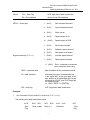
Communications protocol details
Master (Host controller) transmit data packet format:
All transmissions originating from a Host controller must have the following format:
FG1 [DA] [CMD]
Where
([DATA]) [CS] FG2
FG1 = Start Flag
0x7E, flags start of data transmission
DA = Drive Address *
valid addresses { 1 … 63 }
CMD = Master Command
‘R’
(0x52)
Run command
‘S’
(0x53)
Stop command
**see note below
‘A’
(0x41)
Motor current request
**see note below
‘Z’
(0x5A)
Speed request in Hz
**see note below
‘M’
(0x4D)
Speed request in RPM
‘T’
(0x54)
Drive Status request
‘V’
(0x56)
Software version request
2
The user manual of B800 Series Rs-485 communication
Bedford (Quanzhou) Electronic Co.,LTd
Keypad mode only (F-12 = 1)
‘P’
(0x50)
Set new speed in Hz
Keypad mode only (F-12 = 1)
‘I’
(0x49)
Increase speed on ramp
Keypad mode only (F-12 = 1)
‘L’
(0x4C)
Reduce speed on ramp
DATA = transmitted data
data will depend on command send
CS = data checksum
calculated at the time of transmission and
is the logical NOT of the byte result of the
byte addition of all transmitted ASCII bytes
excluding the START and STOP flags and
the checksum itself.
i.e. ~ (DA + CMD + ([DATA]))
FG2 = Stop flag
0x7F, flags end of data transmission
*
For communication with the B800 from a Host controller, add the value 128 to the drive
address.
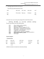
Examples:
1.
Send Run Command to Drive number 01 from intelligent host (F-12 = 1 or 2):
The required data transmission will be
0x7E,
0x38,
0x31,
Start
Drive number
Flag
(128 + 01)
2.
0x35,
0x32,
0x32,
Command
0x46
0x7F
Checksum
Stop
(0x2F)
Flag
Send new target speed of 40.0Hz from intelligent host to drive 05 in keypad mode:
The required data transmission will be
0x7E,
0x38, 0x35,
0x35, 0x30,
Start
Drive number Command
Flag
(128 + 05)
(‘P’)
0x30, 0x39, 0x36, 0x30,
0x35, 0x45
0x7F
Target Speed (40.0Hz)
Checksum
Stop
(0x5E)
Flag
(2400 = 0x0960 sent)
3
The user manual of B800 Series Rs-485
communication
Bedford (Quanzhou) Electronic Co.,LTd
Note that the transmitted speed in Hertz is always 60x the speed required. Therefore 40Hz is
transmitted as 40.0 x 60 = 2400. The high byte is transmitted first. A word (16-bit) value is always
transmitted.
Checksum =
logical NOT
∑
(0x38, 0x35, 0x35, 0x30, 0x30, 0x39, 0x36, 0x30) = 0x5E
Note that the checksum is the least significant byte of the result.
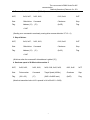
Global commands (to multiple B800s)
Some applications require particular commands to be sent simultaneously to multiple B800s. An
example of this would be a RUN command or a STOP command.
Global commands are sent by using the ASCII code for ‘G’ (0x47) as the drive address.
All B800s receiving a command following this drive address will carry out this command.
There is no reply from the B800s to a global command.
Example:
1.
Send a Run Command to all B800s from intelligent host (F-12 = 1 or 2):
The required data transmission will be
0x7E,
0x34, 0x37,
0x35, 0x32,
0x32, 0x44
0x7F
Start
Global drive
Command
Checksum
Stop
Flag
Address (‘G’)
(‘R’)
(0x2D)
Flag
= 0x47
Slave (B800) reply data packet format:
Whenever a valid data packet is received by the B800, the response will have a format
defined by the following information.
Note that if a valid data packet is received with an incorrect (different) drive address, the
B800 will ignore the data and no response at all will be generated.
All responses to valid commands will be the lower case equivalent to the command received. For
example, if a ‘R’ command is received by the B800, it will respond with an ‘r’ reply.
Format of the B800 response:
FG1
[DA]
[REPLY]
([DATA])
[CS]
4
FG2
The user manual of B800 Series Rs-485
communication
Bedford (Quanzhou) Electronic Co.,LTd
Where
FG1 = Start Flag
0x7E, flags start of data transmission
DA = Drive Address
returns its own Drive address
REPLY = Slave reply
‘r’
(0x72)
Run command executed
‘s’
(0x73)
Stop command executed
‘a’ (0x61)
Motor current
‘z’
Speed request in Hz
(0x7A)
‘m’
Keypad mode only (F-12 = 1)
(0x6D)
Speed request in RPM
‘t’
(0x74)
Drive Status returned
‘v’
(0x76)
Software version returned
‘p’ (0x70)
New speed in Hz loaded
‘i’
(0x69)
Increase speed actioned
‘l’
(0x6C)
Reduce speed actioned
‘e’ (0x65)
Error – command not executed
(error code gives reason why)
DATA = requested data
data will depend on the command received
CS = data checksum
calculated at the time of transmission and
is the logical NOT of the byte result of the
byte addition of all transmitted ASCII bytes
excluding the START and STOP flags and
the checksum itself.
i.e. ~(DA + REPLY + ([DATA]))
FG2 = Stop flag
0x7F, flags end of data transmission
Examples:
1.
Run Command to Drive number 01 carried out (F-12 = 1 or 2):
The resulting reply data transmission will be
0x7E,
Start
Flag
0x30,
0x31,
Drive number
0x37,
0x32,
Reply (‘r’)
5
0x33,
0x35
Checksum
0x7F
Stop
Flag
The user manual of B800 Series Rs-485
communication
Bedford (Quanzhou) Electronic Co.,LTd
2.
New target speed of 40.0Hz set in drive 05:
The resulting reply data transmission will be
0x7E,
0x30, 0x35,
0x37, 0x30,
0x33, 0x33,
0x7F
Start
Drive number
Reply (‘p’)
Checksum
Stop
Flag
Flag
In the event of an error occurring, the message will have the following format:
[Start Flag],
[Drive Addr],
[‘e’],
[error code],
[checksum],
[stop flag]
The error code will have one of the following values:
0x02
0x91
0x92
0x93
0x94
0x95
0x97
0x98
0x99
0x9A
Drive in Standby (status information)
B800 not in keypad mode
B800 speed in RPM not available (F-10 = 0)
B800 running – command cannot be carried out
B800 stopped – command cannot be carried out
Invalid data – incorrect checksum
Invalid command – command not recognized
B800 parameters locked – command cannot be carried out
B800 hardware enable not present
B800 tripped
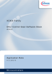
Further examples:
1. Start all drives:
0x7E,
0x34, 0x37,
0x35, 0x32,
0x32, 0x44
0x7F
Start
Global drive
Command
Checksum
Stop
Flag
Address (‘G’)
(‘R’)
(0x2D)
Flag
= 0x47
(Global drive address commands are received by all slaves)
6
The user manual of B800 Series Rs-485
communication
Bedford (Quanzhou) Electronic Co.,LTd
2. Reverse direction of all drives (F-12 = 2):
0x7E,
0x34, 0x37,
0x35, 0x32,
0x32, 0x44
0x7F
Start
Global drive
Command
Checksum
Stop
Flag
Address (‘G’)
(0x2D)
Flag
(‘R’)
= 0x47
(Sending a run command to an already running drive reverses direction if F-12 = 2)
3. Stop all drives:
0x7E,
0x34, 0x37,
0x35, 0x33,
0x32, 0x43
0x7F
Start
Global drive
Command
Checksum
Stop
Flag
Address (‘G’)
(0x2C)
Flag
(‘S’)
= 0x47
(All drives action the command if drive address is global (“G”))
4. Send new speed of 40.0Hz to drive number 5:
0x7E,
0x38, 0x35,
0x35, 0x30,
0x30, 0x39, 0x36, 0x30,
0x35, 0x45
0x7F
Start
Drive number
Command
Target Speed (40.0Hz)
Checksum
Stop
Flag
(128 + 05)
(‘P’)
(2400 = 0x0960 sent)
(0x5E)
Flag
(Note that transmitted value is 60 x speeds in Hz ie 60x 40.0 = 2400)
7