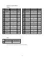
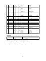
1
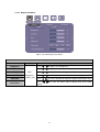
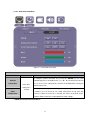
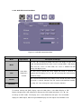
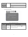
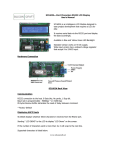
1. Introduction
1.1. About the Product
This product is a high quality TFT LCD panel. It is designed to meet the demanding
performance requirements of today’s business and industrial applications.
1.2. Notice
a. Do not touch the LCD panel surface with sharp or hard objects.
b. Do not use abrasive cleaners, waxes or solvents for cleaning, use only a dry or damp, soft
cloth.
c.
Use only with a high quality, safety-approved, AC/DC power adapter.
1.3. Check List
Before using this monitor, please make sure that all the items listed below are present in your
package
1. VGA cable
x1
2. AC to DC adapter
x1
3. Power cable
x1
4. User manual
x1
5. DVI cable (optional)
x1
6. Audio cable (optional)
x1
7. 24V to 12V transfer board(Optional)
X1
If any items are missing or damaged, please contact your dealer immediately.
5
2. Remote Control
2.1. Install Battery in the Remote Control
Insert two AAA Alkaline batteries and match the (+) and (-) on battery to the marks inside the
battery compartment.
Service life of battery:
1. The battery normally last for about one year although this depends on how often and for
what operations the remote control is used.
2. If the remote control unit fails to work even then it’s operated near the player, please
replace the battery.
2.2. Remote Control Key Definitions
Key
/
Function
Description
Power
Power on/off
Auto
Auto Adjust
Source
Switch input source
Swap
Swap images in PIP/PAP mode
Menu
Display OSD menu
Volume
Adjust volume
PIP
Perform PIP mode
Flip
Flip image
Exit
Return to the previous menu level
Reset
Factory reset
Scaling
Change the scaling mode to 1:1,
Fill or aspect
Auto-color
perform Auto-Color Balance
Mute
Mute
Navigating to Up/Down/Left/Right
/
Select
/
Enter
C1
C2
6
Execute
(optional) Switch to Component 1
mode
(optional) Switch to Component 2
mode
CVBS
(optional) Switch to CVBS mode
VGA
(optional) Switch to VGA mode
3. Kit Memo (Optional for 24V input DC solution)
Warning:
1. See the instruction if the DC adapter is 12V or 24V. If the DC adapter is
24V DC, need to come with “24V to 12V power transfer board”.
2. 24V to 12V Power transfer board installation Guide:
BEFORE connecting power cord to AC outlet, please ensure ADAPTER CABLE, POWER
CABLE to AD BOARD and INVERTER CABLE have been connected. This action prevents
volt converter board (GAP-P0420) from noise issue. This issue does not influence any
function.
7
4. Input Signals Overview
The default output signal is VGA for the main display and S-Video for PIP display. The LCD
output can be configured to use any of the available input formats (VGA, DVI, S-Video, and
Composite).
Monitor Connectors
**Please Note: Some connectors are optional depends on the product model**
4.1. Power & Signal Connections
4.1.1. Power:
Switch off the power on both your monitor and your computer.
The Power Switch is located at the leftmost button of the keypad.
4.1.2. Power cable connection:
Connect the power cord to the AC outlet, and connect the power to the monitor through the
AC/DC adapter.
4.1.3. VGA cable connection:
Plug 15-pin VGA signal cable to the VGA connector in the rear of PC system, and plug the
other end to the monitor.
Secure cable connectors with screws.
8
4.2. Optional Cable Connections
The LCD monitor is designed to work with a variety of compatible video sources. Due to the
possible deviations between these video sources, you may have to make adjustments to the
monitor settings from the OSD menu when switching between these sources.
4.2.1. DVI cable connection (Optional):
Plug the DVI signal cable to the DVI connector in the rear of the PC system, and plug the other
end to the monitor.
Secure cable connectors with screws.
4.2.3 RS232 cable connection (Optional):
You will be able to develop your own application software utilizing the built-in RS232 command
code. The application software can send command from PC to LCD monitor via RS232 port to
control LCD monitor. Please refer to Appendix B for built-in RS232 command code.
5. Using the LCD Monitor
5.1 OSD Key Definition
a. POWER
Initiates power-up sequence from low power mode or enters low lower mode from normal
operation.
b. SWAP/AUTO
i. When PIP is disabled, this will perform Auto Adjustment.
ii. When PIP is enabled, it switches the image in the Main Display to the PIP Display and
vice versa. When image side-by-side (PAP mode) is active, the SWAP key exchanges
the left and right displays.
c. PIP/EXIT
i. When OSD is disabled, it cycles through the available PIP display modes. Repeated
keystrokes will change the size of the PIP display to side-by-side (PAP) display, and
then back to normal display.
9
ii. When OSD is enabled, it returns to the previous menu level or closes the OSD if
pressed at the Main Menu level.
d. ENTER/MENU
i. When OSD is disabled, it displays the OSD Main Menu.
ii. When OSD is enabled, it confirms a selection.
e. LEFT
Moves left when navigating the Main Menu and Sub Menu. It also decrements a slider bar.
f. RIGHT/SOURCE
i. When OSD is disabled, it cycles through the available input sources for the Main
Display.
ii. When OSD is enabled, it moves right when navigating the Main Menu and Sub Menu
and increments a slider bar.
g. UP
i. Selects the previous item in the Item Menu.
h. DOWN
i. Opens the Main Display Source Menu, PIP Display Source Menu and Item Menu.
ii. Selects the next item in the Item Menu.
5.2 OSD Hot Keys (Flip image and Auto)
Function
Mirror Image
Hot Key
Press “
” and “
” simultaneously to get a mirror image
from the original source.
Upside-down Image
Press “
” and “
” simultaneously twice to get an upside
down image from the original source.
Mirror
+
Upside-down
Press “
” and “
” simultaneously three times to get a
Image
mirror + upside down image from the original source.
Auto-Color Balance
When the OSD menu is disabled, press “
simultaneously to perform Auto-Color Balance.
10
” and “
”
5.3 OSD Menu System
The OSD menu system consists of four menu types: Main Menu, Source Menu, Sub Menu and
Item Menu.
Menu
Description
Default / Normal
No menus are displayed.
Main Menu
The first level system control. Accepts “
” ”
” to navigate, “
” to
access Source Menu, and “ENTER” to access Sub Menu.
Source Menu
Input sources are chosen at this level. Accepts “
”“
” and “ENTER” for
selecting input source. Accepts “EXIT” key to return to Main Menu
without changing input source.
Sub Menu
The second level system control. Accepts “
” or “ENTER” to access the
Item Menu. Accepts EXIT key to return to Main Menu.
Item Menu
The third level system control. Accepts “
” “
” and “ENTER” for
adjusting control features. Accepts “EXIT” to return to previous menu
(either Main or Sub Menu).
Table 1: OSD Menu Description
5.3.1. Main OSD Menu
Figure 3.1: OSD Main Menu
Main Display
a. Press “ ” to enter Main Display Source Menu.
b. Press “ENTER” to enter Main Display Sub Menu.
PIP Display
a. Press “ ” to enter PIP Display Source Menu.
b. Press “ENTER” to enter Main Display Sub Menu.
11
OSD Control
Press “ENTER” to enter OSD Control Item Menu.
Audio (Optional)
Press “ENTER” to enter Audio Item Menu.
Factory Reset
Press “ENTER” to enter Factory Reset Item Menu.
**Please Note: The PIP function is active only when the Main Display is in VGA input. **
5.3.2. OSD Source Menu
There are VGA, DVI, S-Video, and Composite ports on the monitor. The VGA port and DVI port
both support PC graphics signals as well as 1080i video signals. The S-Video and Composite
ports support only video signals.
When either the Main Display or PIP Display is selected, press “
Source Menu. Use “
”/“
” to navigate the OSD
” to select an input source In the Source Menu. Press “ENTER” to
save the current selection. Press “EXIT” to return to the Main Menu without saving.
**Please Note: The Source Menus for both the Main Display and PIP Display are
identical in appearance**
12
Figure 3.2: OSD Source Menu
VGA
Composite
Press “ENTER” to set VGA as input
Press “ENTER” to set Composite as
source.
input source.
S-Video
DVI
Press “ENTER” to set DVI as input
Press “ENTER” to set S-Video as
source.
input source.
5.3.3. OSD Sub Menu
When either the Main Display or PIP Display is selected in the Main Menu, press “ENTER” to
access the Sub Menu. This Sub Menu gives the user access to Display / Image / Position /
Color / PIP Control Item Menus. Note that the Image Item Menu is not accessible for the PIP
Display. To access each of these Item Menus, press either the “ENTER” or “
”.
5.3.4. Item Menu
Press “
”/“
” to cycle through the Item Menu. Press “ENTER” or “
” to access the Item
Menu currently selected. Note that the contents of the Item Menu are dependent on the input
source, which is currently active.
13
5.3.4.1. Display Item Menu
Figure 3.4: OSD Display Item Menu
Display Item Menu
Menu
Input Source
Brightness
Press “ ” / “ ” to adjust screen brightness.
Contrast
Press “ ” / “ ” to adjust contrast.
Internal Brightness
VGA /
Hue
Composite /
Saturation
S-Video / DVI
Flesh-Tone
Description and Usage
Press “ ” / “ ” to adjust the internal brightness of the screen.
Press “ ” / “ ” to select hue to obtain the desired color settings.
Press “ ” / “ ” to select saturation to adjust the optimal color degree level.
Press “ ” / “ ” to select Off, Weak, Soft or Strong effect for the Main
Display.
14
5.3.4.2. OSD Image Item Menu
Figure 3.5: OSD Image Item Menu
Image Item Menu
Menu
Input Source
Description and Usage
Change the scaling mode by using the “◄” / “►” buttons to select 1:1, Fill
VGA /
Scaling
Composite /
S-Video / DVI
or aspect. Press “ENTER“ to activate the selected Scaling mode.
In 1:1 mode, the input image is centered on the screen. In Fill mode, the
input image is stretched (or compressed) to fill the available display area. In
Aspect mode, the input image is stretched (or compressed) by the same
horizontal and vertical factor.
Initiate this to have the monitor logic to choose the best settings for the
current input signal. The only button available is “SELECT”. Note this may
Auto-Adjust
change the values of Phase and Clock, and there is no ‘undo’ feature.
Phase
Clock
VGA
Adjust Phase to optimize the display quality by using “◄” / “►” to change
the value.
Select Clock to adjust the horizontal screen size by using “◄” / “►” to
change the value.
15
5.3.4.3. OSD Image Item Menu for Composite and S-Video
Figure 3.6: OSD Image Item Menu for Composite/S-Video
Image Item Menu for Composite and S-Video
Menu
Input Source
Description and Usage
The sharpness of the image may be optimized by using “◄” / “►” to
Sharpness
change the value of the slider bar.
To activate or deactivate MPEG noise reduction, use “◄” / “►” to change
MPEG NR
the value between 0-15.
Composite /
Noise Reduction
Angle Filtering
Film Mode Detect
S-Video
To activate or deactivate noise reduction, use “◄” / “►” to change the
value to either Off or On.
To activate or deactivate angle filtering, use “◄” / “►” to change the value
to either Off or On.
To activate or deactivate film mode detection, use “◄” / “►” to change the
value to either Off or On.
Please Note:
Adaptive De-interlacing / Noise Reduction / Angle Filtering / Film Mode Detection are not
available for progressive video inputs. For interlaced video inputs, Adaptive De-interlacing /
Noise Reduction / Angle Filtering / Film Mode Detection can be configured only when the video
signals are routed through video channel and pass the bandwidth checking.
16
5.3.4.4. OSD Position Item Menu
Figure 3.6: OSD Position Item Menu
Position Item Menu
Menu
Input Source
Description and Usage
Move the screen up or down by using “◄” / “►” to change the vertical
Vertical
VGA
position value.
Move the screen left or right by using “◄” / “►” to change the horizontal
Horizontal
position value.
Change the current Zoom setting only to the Main Display, using “◄” / “►”
to select either In or Out. Zoom is at a temporary setting and will be lost at
Zoom
power down.
Horizontal Pan
VGA / DVI /
Horizontal Pan is unavailable until the user performs a Zoom In action.
Composite /
Using “◄” / “►” to select either Left or Right to change the current
S-Video
Horizontal Pan setting. Pan settings will be lost at power down.
Vertical Pan is unavailable until the user performs a Zoom In action. Using
Vertical Pan
“◄” / “►” to select either Up or Down to change the current Vertical Pan
setting and. Pan settings will be lost at power down.
17
5.3.4.5. OSD Color Item Menu
Figure 3.7: OSD Color Item Menu
Color Item Menu
Menu
Input Source
Description and Usage
To configure gamma correction, by pressing the ENTER key; the OSD
should display three selectable items. Use “◄” / “►” to change the value to
Gamma
Corrections
VGA / DVI /
Composite /
S-Video
Off, 1.8, or 2.2. The setting will be saved in the NVRAM when exiting this
control feature item.
To configure color temperature, use “◄” / “►” to change the value to 9300
Color
K, 6500 K, or User Preset to set a color temperature to suit your own
Temperature
preference. When User Preset is selected, the values of the Red, Green,
and Blue sliders below are used to determine color settings.
** SRGB function has been disabled**
18
5.3.4.6. OSD PIP Control Item Menu
Figure 3.8: OSD PIP Control Item Menu
PIP Control Item Menu
Menu
Input Source
Description and Usage
Use “◄” / “►” to change the Mode value to be Off, Single, or PAP. In Off
mode, the Main display fills the entire screen. In Single mode, a PIP display
Mode
floats over the screen. In PAP mode, the screen is divided into two
side-by-side display areas.
Size
VGA / DVI /
PIP Size can be altered only when Single PIP mode is selected. To
Composite /
configure the PIP display size, use “◄” / “►” to change the value to Small,
S-Video
Vertical
Medium or Large.
Both vertical and horizontal PIP position can be altered only when Single
PIP mode is selected. Configure the PIP Vertical and Horizontal Position,
by using “◄” / “►” to change the value using the slider bar.
Horizontal
To activate side-by-side (PAP) display, open the Main Menu, select Main Display or PIP
Display. Navigate to the PIP control Item, and open the PIP Control Item Menu. Use “◄” / “►”
to change to ‘PAP’ mode. The display area is now divided into two parts. The left window
displays the Main output, while the right window displays the PIP output. Each window is half
19
size of the total display area. Each input is scaled down to fit the window.
To change the size and position of the PIP Display, use “◄” / “►” to change the Mode to
‘Single’. Select the Size item and use “◄” / “►” to change between Small, Medium, and Large
displays. Select the Horizontal Position and Vertical Position sliders and use “◄” / “►” to
adjust the screen position of the floating PIP Display.
Note that the PIP screen can have any position on the screen. This can be achieved by
adjusting both Horizontal and Vertical positions.
5.3.4.7. OSD Item Menu
Figure 3.9: OSD Item Menu
OSD Item Menu
Menu
Input Source
Description and Usage
Vertical
VGA / DVI /
Use “◄” / “►” to change the value of the slider bar to configure the OSD
Composite /
Vertical and Horizontal Position. The OSD itself is moved each time the
Horizontal
S-Video
value is adjusted.
Use “◄” / “►” to change the value of the slider bar to configure the OSD
Blend
Transparency Blend. The transparency of OSD icons is changed each time
20
the value is adjusted. Some OSD elements may not be affected by Blend
settings.
The OSD automatically closes itself if no buttons are pressed for a defined
amount of time. To configure the OSD Time-Out, use “◄” / “►” to change
Time-Out
the value of the slider bar. A value of 0 disables OSD Time-Out, causing
the OSD to remain visible until closed by the user.
To increase the size of the OSD, select Yes for OSD zoom. By default,
OSD zoom is set to No, or turned off. Changing this option to Yes increases
OSD Zoom
the size of the OSD. On lower resolution panels, the OSD zoom feature
may cause the OSD to extend beyond the screen.
5.3.4.8. OSD Audio Item Menu (Optional)
Figure 3.10: OSD Audio Item Menu
Audio Item Menu
Menu
Volume
Balance
Input Source
Description and Usage
VGA / DVI /
To adjust the volume, use “◄” / “►” to change the value of the slider bar to
Composite /
increase or decrease the volume.
S-Video
To configure the audio balance, either left or right, use “◄” / “►” to change
the value of the slider bar to change the value.
21
Increase or decrease the audio treble by using “◄” / “►” to change the
Treble
value.
To configure the bass, use “◄” / “►” to change the bass value.
Bass
To turn mute off/on, select either On/Off for Mute. By default, mute is set to
Mute
No, or turned off.
5.3.4.9. Factory Reset Item Menu
Figure 3.11: OSD Factory Reset Item Menu
Factory Reset Item Menu
Menu
Input Source
Description and Usage
To reset all settings to factory defaults, open the Factory Reset Item Menu.
Factory Reset
VGA / DVI /
Use “◄” / “►” to select the “Yes” option, and press “ENTER“.
Composite /
WARNING: All user adjustments will be lost. Press “EXIT“ to return to the
S-Video
Main Menu without making changes.
22
6. Cleaning the Monitor
1. Make sure the monitor is turned off.
2. Never spray or pour any liquid directly on the screen or case.
3. Wipe the screen with a clean, soft, lint-free cloth. This removes dust and other particles.
4. The display area is highly prone to scratching. Do not use ketone type material (ex.
Acetone), Ethyl alcohol, toluene, ethyl acid or Methyl chloride to clear the panel. It may
permanently damage the panel and void the warranty.
5. If it is still not clean enough, apply a small amount of non-ammonia, non-alcohol based glass
cleaner onto a clean, soft, lint-free cloth, and wipe the screen.
6. Don’t use water or oil directly on the monitor. If droplets are allowed to drop on the monitor
permanent staining or discoloration may occur.
7. Disclaimer
We do not recommend using any ammonia or alcohol-based cleaners on the monitor screen or
case. Some chemical cleaners have been reported to damage the screen and/or case of the
monitor. Seller will not be liable for damage resulting from the use of any ammonia or
alcohol-based cleaner.
8. Troubleshooting
If your monitor fails to operate correctly, consult the following chart for possible solution before
calling for repairs:
Condition
1. The picture does not
appear
Check Point
Check if the signal cable is firmly seated in the socket.
Check if the Power is ON at the computer
Check if the brightness control is at the appropriate position, not at the
minimum.
2. The screen is not
synchronized
Check if the signal cable is firmly seated in the socket.
Check if the output level matches the input level of your computer.
Make sure the signal timings of the computer system are within the
specification of the monitor.
If your computer was working with a CRT monitor, you should check the
current signal timing and turn off your computer before you connect the
VGA Cable to this monitor.
3. The position of the
Adjust the H-position, and V-position, or Perform the Auto adjustment.
screen is not in the
23
center
4. The screen is too bright Check if the brightness or contrast control is at the appropriate position,
(too dark).
not at the Maximum (Minimum).
5. The screen is shaking or Perform the Auto adjustment..
waving
Moving all objects which emit a magnetic field such as motor or
transformer, away from the monitor.
Check if the specific voltage is applied.
Check if the signal timing of the computer system is within the
specification of monitor.
If you are unable to correct the fault by using this chart, stop using your monitor and contact
your distributor or dealer for further assistance.
24
Appendix A: Supported Modes
Graphics
No.
Resolution
Frequency (Hz)
Note
No.
Resolution
Frequency (Hz)
Note
1
640x350
70
IBM
19
1024x768
72
IBM
2
640x350
85
VESA
20
1024x768
75
VESA
3
640x400
56
21
1024x768
85
VESA
4
640x400
70
IBM
22
1280x768
60
5
640x400
85
VESA
23
1152x864
70
6
640x480
72
VESA
24
1152x864
75
7
640x480
75
VESA
25
1280x960
60
VESA
8
640x480
80
VESA
26
1280x960
85
VESA
9
720x350
70
IBM
27
1280x1024
60
VESA
10
720x400
70
IBM
28
1280x1024
60
HP
11
720x400
85
VESA
29
1280x1024
67
IBM
12
800x600
56
VESA
30
1280x1024
70
NCD
13
800x600
60
VESA
31
1280x1024
72
HP
14
800x600
72
VESA
32
1280x1024
75
VESA
15
800x600
75
VESA
33
1280x1024
85
VESA
16
800x600
85
VESA
34
1600x1200
60
VESA
17
1024x768
60
VESA
35
1920x1200
60
VESA
18
1024x768
70
VESA
36
1366x768
60
Video
No.
1
NTSC / 480I / 525I
720 x 240 x 60I
2
PAL / 576I /625I
720 x 288 x 50I
Not all modes will be supported, due to different panel brands
25
Appendix B: Using RS-232 Command Code to set system (Optional)
RS232 setting:
Baud Rate = 115200, Data Bits=8, Parity = None, Stop Bits=1
NO.
Function
Length Command index
Value
Checksum(*1)
0xBB=Power On
1 Power
0x05
0x40
0x00 0=Power On 1=Power Off
0xBA=Power Off
2 Auto
0x05
0x40
0x01 0=Auto
0xBA=Auto
3 Recall
0x05
0x40
0x02 0=Recall
0xB9=Recall
4 WhiteBalance
0x05
0x40
0x03 0=WhiteBalance
0xB8=WhiteBalance
5 Main Input Source 0x05
6 Pip Input Source
0x05
0x40
0x40
0=VGA
0xB7=VGA
1=DVI
0xB6=DVI
2=CVBS
0xB5=CVBS
3=Svideo
0xB4=S-Video
4=Component 1
0xB3=Component 1
5=Component 2
0xB2=Component 2
0=VGA
0xB6=VGA
1=DVI
0xB5=DVI
2=CVBS
0xB4=CVBS
3=Svideo
0xB3=S-Video
4=Component 1
0xB2=Component 1
5=Component 2
0xB1=Component 2
0x04
0x05
7 Brightness
0x05
0x40
0x10 0x00~0x64
0xAB=00 ~ 0x47=100
8 Contrast
0x05
0x40
0x11 0x00~0x64
0xAA=00 ~ 0x46=100
9 Hue
0x05
0x40
0x12
0x00~0x2D (0~45)
0xA9=00 ~ 0x7C=45
0x81 ~0xAD(-1~-45)
0x28= -1 ~ 0xFC= -45
10 Saturation
0x05
0x40
0x13 0x00~0x64
0xA8=00 ~ 0x44=100
11 InterBright
0x05
0x40
0x14 0x00~0x64
0xA7=00 ~ 0x43=100
0=PIP Off
12 PIP
13 PIP Size
14 Scaling
0x05
0x05
0x05
0x40
0x40
0x40
0x20 1=PIP
0x9B=PIP Off
0x9A=PIP
2=PAP
0x99=PAP
1=Small
0x99=Small
0x21 2=Middle
0x98=Middle
3=Large
0x97=Large
0=1:1
0x99=1:1
0x22 1=Fill
0x98=Fill
2=Aspect
26
0x97=Aspect
15 sRGB
0x05
16 Gamma
0x05
17 Color Temp
0x05
0x40
0x40
0x40
0=Off
0x8B=Off
1=On
0x8A=On
0=OFF
0x8A=OFF
0x30
0x31 1=Gamma 1.8
0x89=Gamma 1.8
2=Gamma 2.2
0x88=Gamma 2.2
0=user
0x89=User
0x32 1=9300K
0x88=9300K
2=6500K
0x87=6500K
18 Color-R
0x05
0x40
0x33 0x00-0xFF
0x88=00 ~ 0x89=255
19 Color-G
0x05
0x40
0x34 0x00-0xFF
0x87=00 ~ 0x88=255
20 Color-B
0x05
0x40
0x35 0x00-0xFF
0x86=00 ~ 0x87=255
21 Volume
0x05
0x40
0x50 0x00-0x64
0x6B=00 ~ 0x07=100
22 Balance
0x05
0x40
0x51 0x00~0x64
0x6A=00 ~ 0x06=100
23 Treble
0x05
0x40
0x52 0x00~0x0E
0x69=00 ~ 0x5B=14
24 Bass
0x05
0x40
0x53 0x00~0x0E
0x68=00 ~ 0x5A=14
25 Mute
0x05
0x40
0x54
26 Flip
0x05
0x40
0=Mute On
0x67=Mute On
1=Mute OFF
0x66=Mute Off
0=Normal
0x5B=Normal
1=HFlip
0x5A=HFlip
2=VFlip
0x59=VFlip
3=HVFlip
0x58=HVFlip
0x60
:
Reply Value
ACK
3
C F1
Transmission PASS
NSP
3
D F2
Transmission FAILED
: Length, Command, index, Value, Checksum
Example:0x05, 0x40, 0x00, 0x01, 0xba => Power Off system.
Format
*1:
Checksum is 2’s complement of sum of length and all messages.
27
Appendix C : Using RS-232 Command Code to check system status (optional)
Command(Tx)
Acknowledgement(Rx)
Function
Length
Command index Checksum(*1) Length
index Value
Power
0x04
0x30
0x00
0x00
0xCC
0x04
Main Input
0x04
0x30
0x04
0xC8
0x04
0x30
0x05
0xC7
0x04
0=Power On
0xFC=Power On
1=Power Off
0xFB=Power Off
0=VGA
0xF8=VGA
1=DVI
0xF7=DVI
2=CVBS
0xF6=CVBS
3=Svideo
0xF5=Svideo
4=C1
0xF4=Component 1
5=C2
0xF3=Component 2
0=VGA
0xF7=VGA
1=DVI
0xF6=DVI
2=CVBS
0xF5=CVBS
3=Svideo
0xF4=Svideo
4=C1
0xF3=Component 1
5=C2
0xF2=Component 2
0x04
Source
PIP input source 0x04
Checksum(*1)
0x05
0xEC=0 ~
Brightness
0x04
0x30
0x10
0xBC
0x04
0x10
0x00-0x64
0x88=100
0xEB=0 ~
Contrast
0x04
0x30
0x11
0xBB
0x04
0x11
0x00-0x64
0x87=100
Hue
0x04
0x30
0x12
0xBA
0x04
0x00~0x2D
0xEA=0~0xBD=45
0xAD~0x81
0x3D=-45~0x69=-1
0x12
0xE9=0 ~
Saturation
0x04
0x30
0x13
0xB9
0x04
0x13
0x00-0x64
0x85=100
0xE8=0 ~
InterBright
0x04
0x30
0x14
0xB8
0x04
0x14
0x00-0x64
0x84=100
PIP
PIP Size
Scaling
0x04
0x04
0x04
0x30
0x30
0x30
0x20
0x21
0x22
0xAC
0x04
0xAB
0x04
0xAA
0x04
28
0x20
0x21
0x22
0=Pip Off
0xDC=PIP Off
1=PIP
0xDB=PIP
2=PAP
0xDA=PAP
1=Small
0xDA=Small
2=Middle
0xD9=Middle
3=Large
0xD8=Large
0=1:1
0xDA=1:1
1=Fill
0xD9=Fill
2=Aspect
0xD8=Aspect
sRGB
0x04
0x30
0x30
0x9C
0x04
0=Off
0xCC=OFF
1=On
0xCB=ON
0x30
0=OFF
Gamma
0x04
0x30
0x31
0x9B
0x04
0x31
1=Gamma
0xCB=OFF
1.8
0xCA=Gamma 1.8
2=Gamma
0xC9=Gamma 2.2
2.2
Color Temp
0x04
0x30
0x32
0x9A
0x04
0x32
0=user
0xCA=user
1=9300K
0xC9=9300k
2=6500K
0xC8=6500k
0xC9=0 ~
Color-R
0x04
0x30
0x33
0x99
0x04
0x33
0x00-0xFF
0xCA=255
0xC8=0 ~
Color-G
0x04
0x30
0x34
0x98
0x04
0x34
0x00-0xFF
0xC9=255
0xC7=0 ~
Color-B
0x04
0x30
0x35
0x97
0x04
0x35
0x00-0xFF
0xC8=255
0xAC=0 ~
Volume
0x04
0x30
0x50
0x7C
0x04
0x50
0x00-0x64
0x48=100
0xAB=0 ~
Balance
0x04
0x30
0x51
0x7B
0x04
0x51
0x00-0x64
0x47=100
Treble
0x04
0x30
0x52
0x7A
0x04
0x52
0x00-0x0E
0xAA=0 ~ 0x9C=14
Bass
0x04
0x30
0x53
0x79
0x04
0x53
0x00-0x0E
0xA9=0 ~ 0x9B=14
0=Mute On
0xa8=Mute On
Mute
0x04
0x30
0x54
0x78
0x04
0x54
1=Mute OFF 0xa7=Mute OFF
Flip
0x04
0x30
0x60
0x6C
0x04
0=Normal
0x9C=NORMAL
1=HFlip
0x9B=HFlip
2=VFlip
0x9A=VFlip
3=HVFlip
0x99=HVFlip
0x60
:
Reply Value
ACK
Acknowledgement code
Transmission PASS
NSP
3
Transmission FAILED
D F2
: Length, Command, index, Checksum / Length, Index, Value, Checksum
Example:0x04, 0x30, 0x00, 0xCC => Check Power status.
Format
If Reply is 0x04, 0x00, 0x00, 0xFC=> System power on
*1: Checksum is 2’s complement of sum of length and all messages.
29