1
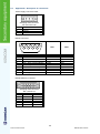
2 KONCOM USER MANUAL KON-215-10-01.3-v.2.0-E INDEX: 1 INTRODUCTION................................................................................................................................... 4 1.1 General.......................................................................................................................................... 4 1.2 Abbreviations ................................................................................................................................ 4 2 TECHNICAL DATA .............................................................................................................................. 4 2.1 Description .................................................................................................................................... 4 2.1.1 2.1.2 2.2 2.3 2.3.1 2.3.2 3 KONCOM RS ...................................................................................................................................... 4 KONCOM RSFO MUX ........................................................................................................................ 5 Physical data ................................................................................................................................. 5 Technical data ............................................................................................................................... 6 Connections ........................................................................................................................................ 6 Environment ........................................................................................................................................ 7 OPERATING INSTRUCTIONS ............................................................................................................. 9 3.1 Exterior .......................................................................................................................................... 9 3.1.1 3.1.2 3.2 3.3 3.3.1 3.3.2 View of a KONCOM RS transducer .................................................................................................... 9 View of a KONCOM RSFO MUX transducer..................................................................................... 10 Installation - removal ................................................................................................................... 11 Connectivity ................................................................................................................................. 13 Linking KONCOM RS signal transducer ........................................................................................... 13 Linking KONCOM RSFO MUX signal transducer.............................................................................. 14 3.4 Labelling ...................................................................................................................................... 18 MAINTENANCE .................................................................................................................................. 19 4.1 General........................................................................................................................................ 19 4.2 Breakdown .................................................................................................................................. 19 4.3 Storage ........................................................................................................................................ 19 4.4 Transport ..................................................................................................................................... 19 5 APPENDIX .......................................................................................................................................... 19 5.1 Appendix A – Display of the standard RS232 cable ................................................................... 19 5.2 Appendix B – Description of connections ................................................................................... 20 4 3 KON-215-10-01.3-v.2.0-E KONCOM USER MANUAL 1 INTRODUCTION 1.1 General KONCOM is a unified name for Koncar-s group of converters used for converting communication interfaces. They are designed for use in industrial environments, have an increased resistance to interference, connect to a wide range of power sources, are encased in a metal chassis, compact and easy to use product. There are two basic types of transducers: KONCOM RS – Signal converter from RS232 interface to one of the RS485/RS422 interfaces with mutual isolation voltage of 2.5 kV. KONCOM RSFO MULTIPLEXER – Signal converter (multiplexer) from one of the RS232/RS485/RS422/FO interfaces to five (or six) FO (fiber optic) interfaces. 1.2 2 2.1 Abbreviations AC Alternating Current DC Direct Current EIA Electronic Industries Association FO Fiber optic LED Light Emitting Diode MTBF Mean time Between Fault NC Not Connected RS232 Standard for Serial Binary Data Interchange RS422 Standard for unidirectional balanced interface RS485 Standard for bidirectional balanced interface TECHNICAL DATA Description 2.1.1 KONCOM RS KONCOM RS is a signal transducer from RS232 to RS485 or RS422 interface. Between RS232 and RS485/RS422 there is a mutual isolation voltage of 2.5 kV. The converter is completely transparent as far as baud rate and numbers of bits in the message go. During the communication it is possible to change the message length and speed of transmission without any additional configuration of the device. For the purposes of testing the validity of communication channels is possible loop (connecting Tx to Rx) the RS232 and RS422 interfaces. Termination resistors for RS485 and RS422 are built into the device and can be connected if needed. Communication interfaces have a built-in protection against voltage spikes on the lines. KONCOM - RS 2,5kV RS232 RS232 80-265 VDC DC/DC RS485 RS485 / RS422 Figure 1: Block view of a KONCOM RS signal transducer. 4 KONCOM USER MANUAL KON-215-10-01.3-v.2.0-E 2.1.2 KONCOM RSFO MUX FO multiplexer can operate in three basic modes: As an optical multiplexer when FO1 channel connects to the remaining five channels FO (FO6 ÷ FO2) The RS232 protocol multiplexer FO to six channels (FO1 ÷ FO6) As a multiplexer RS485 or RS422 protocols to six FO channels (FO1 ÷ FO6). There are two basic versions of FO interfaces: MUX1 – designed to connect plastic optical fiber cables (range of approximately 50 m), MUX2 – designed to connect glass optical fiber cables (range of approximately 2000 m). The combination of both optical connections (glass and plastic) is possible. For this converter, the same characteristics for RS232, RS485 and RS422 interfaces apply. The converter is completely transparent as far as baud rate and numbers of bits in the message go. During the communication it is possible to change the message length and speed of transmission without any additional configuration of the device. For the purposes of testing the validity of communication channels it is possible loop (connecting Tx to Rx) the RS232, RS422 interfaces and FO. Termination resistors for RS485 and RS422 are built into the device and can be connected if needed. Communication interfaces have a built-in protection against voltage spikes on the RS232, RS485 and RS422 lines. KONCOM – RSFO MUX FO FO1 FO FO2 RS232 RS232 FO FO3 RS485 / RS422 RS485 FO FO4 FO FO5 FO FO6 80-265 VDC DC/DC Figure 2: Block view of a KONCOM RSFO MUX signal transducer. 2.2 Physical data KONCOM RS KONCOM RSFO MUX1 KONCOM RSFO MUX2 Height 90 mm 93 mm 115 mm Width 55 mm 55 mm 55 mm Depth 130 mm 130 mm 130 mm Weight 450 g 520 g 540 g 5 KON-215-10-01.3-v.2.0-E KONCOM USER MANUAL 2.3 2.3.1 Technical data Connections RS232 interface: Transfer speed ESD protection Over voltage protection Current protection The choice of connection Connection Loop 120 kbps ± 15 kV ± 15 V 125 mA DCE/DTE DB9 yes RS485 interface: Transfer speed ESD protection Over voltage protection Current protection The choice of communication Communication direction Closure 250 kbps ± 15 kV ± 7,5 V 125 mA Half / Full Duplex AUTO / FIX 120Ω FO interface-1 ( plastic fiber ): Wave length Connector type Transfer speed Range Loop 660 nm, HFBR, VPIN 1 Mbd, ≤ 40 m, yes FO interface-2 ( glass fiber ): Wave length Connector type Transfer speed Range Loop 820 nm, ST, FST 5 Mbd, ≤ 2 km, yes Power source: 80÷265VDC, 220 VAC +10% -15%, 18÷80VDC arbitrary ≤ 3 W, class B Supply voltage ver. A Supply voltage ver. B The polarity oft he DC voltage Consumption EMI 6 KONCOM USER MANUAL KON-215-10-01.3-v.2.0-E 2.3.2 Environment Ambience: -5 do +55 °C -25 do +55 °C -25 do +70 °C < 75 % per annum; 95 % 30 days per year. not allowed Temperature operating range Storage temperature Limit temperature during transport Permissible humidity Condensation Security demands: Meets the requirements defined by the standard[9] ( EN 61010 –1 ): o o o Over voltage category Degree of pollution Fire resistance classification III 2 V0 Insulation: Meets the test of insulation defined by the standard EN61010, IEC255-5: ANSI / IEEC37.90.0: Power supply isolation test – the other interfaces Power supply isolation test – the other interfaces Impulse voltage power supply – the other interfaces In intervals of 5 s, class III ). 5,25 kV DC / 1s (parallel capacitator), 3,7 kV AC / 50Hz (no parallel cap.), 5 kV; 1,2/50 us; 0,5 J; ( 3 pos. & 3 neg. The emission of electromagnetic fields: Meets the following requirements for the emission of electromagnetic fields: Allowable emissions in industrial areas (EN 61000-6-4:2008): Limits for harmonic current emissions (EN 61000-3-2:2008): 0 Hz - 400 GHz; 30 MHz - 1 GHz, Class B; Resistance to electromagnetic interference: Meets the following requirements for resistance to electromagnetic interference: Immunity for industrial environments (EN 61000-6-2:2008): 0 Hz - 400 GHz; Resistant to voltage fluctuations and flicker (EN 61000-3-3:1997 + A1: 2008) Resistance to climatic stress: According to standards EN 60068-2-2 and EN 60 068 fulfils the following: o Operating temperature range: Short-term working temperature range: Storage temperature: Limit temperature during transport: Permissible humidity -5 to +55 C; o -20 to +70 C; o -25 to +55 C; o -25 to +70 C; < 75 % per annum; 95 % 30 days per year; condensation is not allowed. 7 KON-215-10-01.3-v.2.0-E KONCOM USER MANUAL Resistance to mechanical stress: Vibration: IEC 60255-21-1, class 1: IEC 60068-2-6: sinusoidal 10-60 Hz, ± 0.035 mm amplitude; increase in frequency 10 octaves / min, 20 cycles in three orthogonal axes. IEC 60255-21-2, class 1: half-wave, 5 g acceleration, duration 11 ms, three shocks in each of 3 orthogonal axes. Shock: Seismic vibrations: IEC 60255-21-2, class 1: sinus; 1-8 Hz; +3.5 mm ampl.: horizontal axis; sinus; 1-8 Hz; +1.5 mm ampl.; vertical axis IEC 60068-3-3: sinus: 8-35 Hz, 1 g acceleration, the horizontal axis; sinus: 8-35 Hz, 0.5 g acceleration, the vertical axis; increase in frequency 1 octave / min, 1 cycle for 3 orthogonal axes. 8 KONCOM USER MANUAL KON-215-10-01.3-v.2.0-E 3 3.1 OPERATING INSTRUCTIONS Exterior 3.1.1 View of a KONCOM RS transducer 9 4 10 9 4 4 9 7 2 1 O N 3 O N 8 10 9 10 9 5 6 Figure 3: View of a KONCOM RS transducer. CODE DESCRIPTION 1 An indication of presence of power supply (LED - green) 2 An indication of presence of handing Tx (LED - yellow) 3 An indication of presence of receipt Rx (LED - yellow) 4 Connector for RS232 interface (DB9) 5 Connector for RS485 and R422 interface 6 Connector for power supply 7 Micro switch S2 8 Micro switch S1 9 Holder for mounting on the rail (35 mm) 10 Earthing terminal 9 KON-215-10-01.3-v.2.0-E KONCOM USER MANUAL 3.1.2 View of a KONCOM RSFO MUX transducer 9 4 10 9 12 11 4 13 15 14 16 9 1 7 2 ON 3 ON 8 10 21 22 19 17 20 18 9 10 9 6 5 Figure 4: View of a KONCOM RSFO MUX1 transducer. CODE DESCRIPTION 1 An indication of presence of power supply (LED - green) 2 An indication of presence of handing Tx (LED - yellow) 3 An indication of presence of receipt Rx (LED - yellow) 4 Connector for RS232 interface (DB9) 5 Connector for RS485 and R422 interface 6 Connector for power supply 7 Micro switch S2 8 Micro switch S1 9 Holder for mounting on the rail (35 mm) 10 Earthing terminal 11 Connector for FO1 – Rx Connector for FO1 – Tx 12 10 KONCOM USER MANUAL KON-215-10-01.3-v.2.0-E Connector for FO2 – Rx Connector for FO2 – Tx 13 14 Connector for FO3 – Rx Connector for FO3 – Tx 15 16 Connector for FO4 – Rx Connector for FO4 – Tx 17 18 Connector for FO5 – Rx Connector for FO5 – Tx 19 20 Connector for FO6 – Rx Connector for FO6 – Tx 21 22 3.2 Installation - removal KONCOM converters are designed for mounting on DIN-rails of the following types: PICTURE CODE NAME EN 50022 Omega – rail EN 50035 G - rail Way of mounting the device on the DIN rail is shown in Figures 5 and 6. SAFETY WARNING! After mounting the device on the rail, it must be the grounded! 11 KON-215-10-01.3-v.2.0-E KONCOM USER MANUAL Mounting: Figure 5: Ways of mounting the "Omega" rack. Figure 6: Ways of mounting the „G“ rack. Removal: SAFETY WARNING! Before you start disassembling the unit, first disconnect its power port, and then all of its remaining ports! Figure 7: Dismantling process. 12 KONCOM USER MANUAL KON-215-10-01.3-v.2.0-E 3.3 Connectivity 3.3.1 Linking KONCOM RS signal transducer Description of micro switches S1 and S2: Micro switches S1 ([8]) and S2 ([7]) are located on the right lateral side of the device. Position "ON" on them has a double meaning: Indicates a first switch in series, Indicates that a switch in this position is connected. Micro switch S1 refers to the setting RS485 (RS422) communication protocol. There are three groups of switches: DIRECTION CONTROL - (switches 2, 3, 4) These switches determine whether the direction of communication is determined to be fixed (FIX - RS422) or it will automatically change depending on the direction of communication (AUTO - RS485). COMMUNICATION MODE - (switches 5, 6) These switches determine the one-way (full duplex RS422) or two-way (half duplex - RS485) communication mode. TERMINATION - (switches 7, 8) With these switches we combine the necessary conclusion of the receiving (RX) and transmit (TX) lines with 120Ω. In the case of RS485 protocol connects to only one conclusion, because the communication takes place by a pair so that the receiving and transmitting lines connected together. SWITCH – S1 1 2 3 4 5 6 DIRECTION CONTROL AUTO Y N Y FIX N Y N COMMUNICATION MOD FULL N N HALF Y Y TERMINATION RX 7 8 Y - ON Y TX N Table 1: Defining the position of the micro switches S1 for the RS485 / RS422 interface. Micro switch S2 refers to the RS232 interfaces settings and testing of communication channels by creating a loop. There are two groups of switches: DCE / DTE - (switches 1, 2, 3, 4) the switch will determine whether the RS232 interface act as a DCE port (for connecting to a PC) or as a DTE port (for connecting to the modem). LOOP - (switches 5, 6, 7, 8, 9, 10) these switches can, the for the purpose of testing, make a loop on the RS232 or RS422 interfaces. In normal operation the loop cannot be connected (NO). SWITCH – S2 DCE/DTE LOOP 1 2 3 4 5 6 7 8 9 10 DCE Y Y N N DTE N N Y Y NO N Y N N Y N RS232 Y N N N N Y RS422 N N Y Y N N Table 2: Defining the position of the micro switches S2. 13 KON-215-10-01.3-v.2.0-E KONCOM USER MANUAL Connecting the RS232 interface: RS232 interface is to be connected to the DB9 connector ([4]). To connect using a standard RS232 interfaces cable (1 to 1) that at one end has a male DB9 connector (for connecting to KONCOM RS), and on another female DB9 connector (for connection to a PC or modem). Details of the cable can be seen in the chapter "Appendix - Display of the standard RS232 cable". Connecting the RS485 interface: 5 4 KONCOM-RS Data-A Data-B GND RS485: 1 RS232: 2 RS485: 2 RS232: 3 RS485: 5 RS232: 5 Rx Tx GND PC2 RS485 RS232 6 10 POW EARTH POW POW: 1 POW: 2 POW: 3 EARTH 220VAC Figure 8: RS485 interface connection diagram. Connecting the RS422 interface: 5 4 KONCOM-RS Tx-A Tx-B Rx-A Rx-B GND RS485 RS485: 1 RS232: 2 RS485: 2 RS232: 3 RS485: 3 RS232: 5 RS485: 4 Rx Tx GND RS485: 5 PC2 RS232 6 10 POW EARTH POW POW: 1 POW: 2 POW: 3 EARTH 220VAC Figure 9: RS422 interface connection diagram. 3.3.2 Linking KONCOM RSFO MUX signal transducer Description of micro switches S1 and S2: Micro switches S1 ([8]) and S2 ([7]) are located on the right lateral side of the device. Position "ON" on them has a double meaning: Indicates a first switch in series, Indicates that a switch in this position is connected. 14 KONCOM USER MANUAL KON-215-10-01.3-v.2.0-E Micro switch S1 refers to the setting of the RS485 (RS422) communication protocol. There are three groups of switches: DIRECTION CONTROL - (switches 2, 3, 4) these switches determine whether the direction of communication is determined to be fixed (FIX - RS422) or it will automatically change depending on the direction of communication (AUTO - RS485). COMMUNICATION MODE - (switches 5, 6) these switches determine the one-way (full duplex RS422) or two-way (half duplex - RS485) communication mode. TERMINATION - (switches 7, 8) with these switches we combine the necessary conclusion of the receiving (RX) and transmit (TX) lines with 120Ω. In the case of RS485 protocol connects to only one conclusion, because the communication takes place by a pair so that the receiving and transmitting lines connected together. SWITCH – S1 1 2 3 4 5 6 DIRECTION CONTROL AUTO Y N Y FIX N Y N COMMUNICATION MOD FULL N N HALF Y Y TERMINATION RX 7 8 Y - ON Y TX N Table 3: Defining the position of the micro switches S1 for the RS485 / RS422 interface. Micro switch S2 refers to the RS232 interface settings and selects the main (MASTER) communication carrier. There are two groups of switches: DCE / DTE - (switches 1, 2, 3, 4) the switch will determine whether the RS232 interface act as a DCE port (for connecting to a PC) or as a DTE port (for connecting to the modem). MASTER - (switches 6, 7, 8, 9, 10) these switches will determine who will be the main carrier of the communication. It may be RS232 / RS485 / RS422 interface (RSxxx), or the optical channel 1 (FO 1). In the configurations where the optical channels are connecting to a ring structure, it is necessary to transmit the signal receiver to the surrender (ECHO) SWITCH – S2 DCE/DTE MASTER 1 2 3 4 DCE Y Y N N DTE N N Y Y 5 6 7 8 9 RSxxx Y N Y N FO N Y N Y ECHO 10 N Table 4: Defining the position of the micro switches S2. Connecting the RS232 interface: RS232 interface is to be connected to the DB9 connector ([4]). To connect we use the standard RS232 interfaces cable (1 to 1) that at one end has a male DB9 connector (for connecting to KONCOM RS), and on another female DB9 connector (for connection to a PC or modem). Details of the cable can be seen in the chapter "Appendix - Display of the standard RS232 cable“. 15 KON-215-10-01.3-v.2.0-E KONCOM USER MANUAL Connecting a RS232 multiplexer: With this connection mode we have a RS232 interface as the main (MASTER) communication carrier that is rerouted to the other six optical channels. KONCOM-RSFO-MUX 11 12 Rx-01 4 RS232: 2 FO-1 Tx-01 RS232: 3 Rx-02 RS232: 5 FO-2 Tx Rx GND1 PC2 Tx-02 Rx-03 RS232 FO-3 Tx-03 Rx-04 FO-4 Tx-04 Rx-05 21 FO-5 Tx-05 Rx-06 22 FO-6 Tx-06 POW EARTH POW POW: 1 POW: 2 POW: 3 10 EARTH 220VAC 6 Figure 10: Connection diagram as RS232 multiplexer. Connecting a RS485 multiplexer: KONCOM-RSFO-MUX 11 12 Rx-01 RS485: 1 FO-1 Tx-01 Rx-02 5 RS485: 2 RS485: 5 FO-2 Data-A Data-B GND Tx-02 Rx-03 Tx-03 Rx-04 RS485 FO-3 FO-4 Tx-04 Rx-05 21 FO-5 Tx-05 Rx-06 22 FO-6 Tx-06 POW EARTH POW POW: 1 POW: 2 POW: 3 10 EARTH 220VAC 6 Figure 11: Connection diagram as RS485 multiplexer. 16 KONCOM USER MANUAL KON-215-10-01.3-v.2.0-E Connecting as an optical multiplexer: When we want to connect the converter as an optical multiplexer channel FO1 then becomes the holder of communication (MASTER) and its signal is transmitted to the remaining 5 FO channels.. KONCOM-RSFO-MUX 11 12 Rx-01 FO-1 Tx-01 Rx-02 FO-2 Tx-02 Rx-03 FO-3 Tx-03 Rx-04 FO-4 Tx-04 Rx-05 21 FO-5 Tx-05 Rx-06 22 FO-6 Tx-06 POW EARTH POW POW: 1 POW: 2 POW: 3 10 EARTH 220VAC 6 Figure 12: Connection diagram for optical multiplexer. Connecting in a ring structure: 11 12 Rx 4 11 Tx 12 Rx 11 12 Tx Rx Tx FO1 FO1 FO1 RSFO-MUX RSFO-MUX RSFO-MUX RS232 RS485 FO2 FO6 --- 5 Figure 13: Connection diagram for a ring structure. Ring structure is achieved through FO1 interface and the ECHO must be turned on (switch pos. 10) on the micro switch S2 ([7]), in order to transmit the signal from the transmitting to the receiving side. ECHO is not switched on only on the device that is the main (MASTER) so that the information would not be eternally circling the loop 17 KON-215-10-01.3-v.2.0-E KONCOM USER MANUAL Connecting in a complex structure: With the KONCOM converters we can realize complex and demanding communication structures. Some of them are shown in Figure 14. RSFO -MUX RSFO -MUX RSFO -MUX RS232 RSFO -MUX FO RSFO -MUX RSFO -MUX FO RS232 RS RS422 RSFO -MUX RSFO -MUX RSFO -MUX RS485 RSFO -MUX FO FO FO FO FO RSFO -MUX RS232 RSFO -MUX RS232 Figure 14: Connecting KONCOM converters in a complex communication structures. 3.4 Labelling Figure 15 shows how the selection of different varieties of communication converters. KONCOM - 0 0 6 A A – 85-265 DC; 220V AC B – 18-80 DC Number of plastic FO connectors Number of glass FO connectors 0 – Converter RS232/RS485/FO to FO 1 – Converter RS232 to RS485/RS422 Figure 15: KONCOM – Selection mode of certain device variants. 18 KONCOM USER MANUAL KON-215-10-01.3-v.2.0-E 4 MAINTENANCE 4.1 General In the event that the device is properly installed it does not require any special maintenance, except for regular cleaning of dust. Cleaning the dust is carried out only with a dry cotton cloth and it is not necessary to interrupt the normal operation of the device. 4.2 Breakdown In the event of failure of the device it must be removed according to the instructions of dismantling the device (see Section 3.2), and send in for repair to the manufacturer or authorized service centres. WARNING! User is not allowed to open the device or repair it! Repairs are carried out exclusively by the manufacturer or authorized service. 4.3 Storage Prior to the device storage it is necessary to check whether storage area is corresponding to the storage conditions defined in the Technical Requirements (Section 2.3.2 Environment). KONCOM converters are stored in the following way: They must be properly packaged, Storage Temperature Permissible humidity Condensation -25 to +55°C, < 75 % per annum, 95% 30 days of the year, not allowed. Note: Do not store broke down devices. 4.4 Transport It is recommended to transport the device in for it anticipated packaging and in a way that eliminates the possibility of its damage. Take into account that during transport they do not put heavier items on the packaged device, because it might damage the connector device 5 5.1 APPENDIX Appendix A – Display of the standard RS232 cable DB9 MALE DB9 FEMALE 1 2 3 4 5 6 7 8 9 1 2 3 4 5 6 7 8 9 Figure 16: Display oft he standard 1 to 1 RS 232 cable. 19 KON-215-10-01.3-v.2.0-E KONCOM USER MANUAL 5.2 Appendix B – Description of connections Power supply connector POW: 1 2 3 Clamping male connector MC 2,5/3-GF-5,08 PIN DESCRIPTION 1 POW 2 EARTH 3 POW RS232 connector: 5 4 3 9 PIN 1 2 3 4 5 6 7 8 9 2 8 7 1 6 Female DB9 connector SIGNAL DESCRIPTION CD – Carrier Detect RD – Received Data TD – Transmitted Data DTR – Data Terminal Ready GND – Signal Ground DSR – Data Set Ready RTS – Request To Send CTS – Clear To Send RI – Ring Indicator DTE DCE INPUT/OUTPUT Input Input Output Output GND Input Output Input NC INPUT/OUTPUT Output Output Input Input GND Output Input Output NC RS485 (RS422) connector: 1 2 3 4 5 6 Clamping male connector MC 1,5/6-G-3,5 PIN RS422 RS485 1 TX - A DATA - A 2 TX - B DATA - B 3 RX - A DATA - A 4 RX - B DATA - B 5 GND GND 6 EARTH EARTH 20 KONCOM USER MANUAL KON-215-10-01.3-v.2.0-E 21 KON-215-10-01.3-v.2.0-E KONCOM USER MANUAL