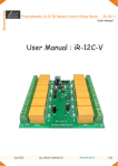
1
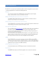
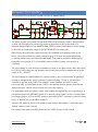
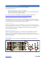
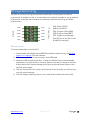
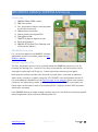
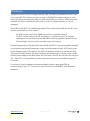
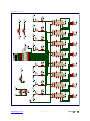
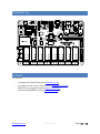
SimPLC
v2.0
User Manual
www.dizzy.co.za
Contents
Introduction............................................................................................................................................................... 3
Overview – Top ........................................................................................................................................................ 4
Power Circuitry........................................................................................................................................................ 5
Microcontroller ....................................................................................................................................................... 6
Real-Time Calendar and Clock (RTCC) ........................................................................................... 6
Reset Button ............................................................................................................................................. 6
Oscillator Socket ...................................................................................................................................... 6
Schematic................................................................................................................................................... 6
Programming........................................................................................................................................................... 7
Bootloader.................................................................................................................................................. 7
SIM800 GSM/GPRS Module ........................................................................................................................... 8
Overview ...................................................................................................................................................... 8
SIM800 Module....................................................................................................................................... 8
Powering On/Off ..................................................................................................................................... 8
Power and Signal Indication ................................................................................................................ 9
Communication ........................................................................................................................................ 9
Speaker and Microphone Connectors ........................................................................................... 9
Schematic................................................................................................................................................ 10
Relays ....................................................................................................................................................................... 11
Schematic................................................................................................................................................ 12
Inputs and Outputs ............................................................................................................................................. 13
IDC10 Headers ..................................................................................................................................... 13
mikroBus Sockets ................................................................................................................................ 13
USB ........................................................................................................................................................................... 14
LCD Connector ..................................................................................................................................................... 14
Drawing ................................................................................................................................................................... 15
Links .......................................................................................................................................................................... 15
Microcontroller I/O Map ................................................................................................................................. 16
Disclaimer .............................................................................................................................................................. 17
www.dizzy.co.za
Revision 1.0
Page 2 of 17
Introduction
The SimPLC is a compact and cost-effective platform which is targeted at remote control
/ monitoring applications. It includes the following features:
Relays
-
Up to 8 relays (rated at 16A/250VAC) allow external devices (such as lights,
pumps, security devices, etc) to be switched on and off.
GSM/GPRS/BlueTooth Communication
-
The SIM800 GSM/GPRS/BlueTooth module provides a convenient means of
wireless communication to/from the board.
RTCC (Real-Time Calendar and Clock)
-
The PIC18F46J50 microcontroller features a built-in RTCC (real-time calendar and
clock), allowing you to perform tasks at set dates / times.
Inputs and Outputs
-
-
Two mikroElektronika (www.mikroe.com) mikroBus sockets allow the functionality of
the system to be easily extended by plugging in any of a huge range of “click”
accessory boards. One application of this is to add up to 8 opto-coupled inputs to
the board (using OPTO click boards).
Ports A, B and D are also exposed via IDC10 headers on the right-hand side of the
board, providing convenient access to any free inputs/outputs. (mikroElektronika
IDC10 type accessory boards can also be plugged into these headers).
USB
-
The PIC18F46J50 microcontroller also features built-in USB (including USB OnThe-Go), and the board includes a miniUSB connector in order to take advantage of
this. This feature could be used to configure the board, and/or for in-field firmware
updates (via the pre-programmed USB bootloader).
LCD Display Connector
-
A convenient Alphanumeric LCD Display connector is included on the board.
FM Radio
-
The SIM800 also features an FM radio (speaker line is used as the antenna).
www.dizzy.co.za
Revision 1.0
Page 3 of 17
Overview – Top
1. Power-supply circuitry.
2. PIC18F46J50 microcontroller, and supporting circuitry.
3. SIM800 GSM/GPRS module with BlueTooth and FM Radio, and supporting
circuitry.
4. Speaker and microphone connectors for SIM800 GSM/GPRS module.
5. Up to 8 relays.
6. IDC10 connectors, exposing Port A, B and D of the microcontroller.
7. mikroBus socket 1.
8. mikroBus socket 2.
9. mikroProg and PICkit programming connectors.
10. miniUSB connector, and supporting circuitry.
11. Alphanumeric LCD connector.
www.dizzy.co.za
Revision 1.0
Page 4 of 17
Power Circuitry
The schematic for the SimPLC’s power circuitry is detailed below:
The power circuitry is centred around a MP4460 buck converter, which is configured to
provide a 3.6V supply to the board. By powering the board on 3.6V, the need for a
separate power supply for the SIM800 GSM/GPRS module is eliminated, and the voltage
is still within the operating range of the PIC18F46J50 microcontroller.
Both DC jack and screw terminal connectors are available for supplying power to the
board. From the connectors, power passes through a 2A fuse and (optional) polarityprotecting diode, before arriving at the MP4460. (The polarity protection diode can be
bypassed, using jumper JP1, for situations where minimum power consumption is
required.)
The input voltage is used directly to activate the relays on the board, and is this required to
be 12V DC. If the relays are not however being used, then the input voltage can be in the
range of 5V – 36V DC.
The input voltage is made available for measurement by the microcontroller by passing it
through a voltage divider, which reduces it by approximately 77% (e.g. 12V would be
reduced to approximately 2.8V). The voltage is made available on PortC.2 of the
microcontroller, provided that jumper JP6 is in the default position (please also see the
“Microcontroller” section of this manual for more information).
For applications where minimum power consumption during standby is of importance, it is
possible to control the MP4460 (switch it on and off) using PortD.7 of the microcontroller,
by changing jumper JP2 to the RD7 position (note that PortD.7 may also be used for Relay
RL17, or the INT pin on mikroBus socket 2).
Jumper JP3, although found in the power supply section of the board, is covered in the
“Relays” section of this manual.
For powering the board via USB, please see the “USB” section of this manual.
www.dizzy.co.za
Revision 1.0
Page 5 of 17
Microcontroller
The microcontroller used on the SimPLC is the PIC18F46J50.
The PIC18F46J50 features:
-
64KB of program memory and 3776B of SRAM.
(Approximately 6800B of program memory are used by the USB-HID bootloader).
Operating frequency up to 48MHz (12MIPS).
For more information on the PIC18F46J50 please download its datasheet from
http://ww1.microchip.com/downloads/en/DeviceDoc/39931d.pdf
Real-Time Calendar and Clock (RTCC)
The PIC18F46J50 features a built-in RTCC, and a 32.768kHz crystal (X2) as well as two
12pF capacitors are connected to the PIC’s PortC.0 (T1OSCO) and PortC.1 (T1OSCI) pins,
in order to facilitate the accurate operation of this peripheral.
Reset Button
A tactile switch (SW2) is connected to the MCLR pin of the microcontroller. Depressing
this button will place the microcontroller in a state of reset. (Note: The reset button will not
work if the MCLR function has been disabled on the PIC by programming it with the
relevant configuration setting).
Oscillator Socket
The Breeze comes programmed to run from the PIC’s internal oscillator. An external
oscillator socket (X1), with 22pF capacitors, is however provided should you wish to
connect an external oscillator. The oscillator socket is connected the PIC’s PortA.6 (CLKO)
and PortA.7 (CLKI) pins.
Schematic
The schematic for the microcontroller, 32.768kHz RTCC oscillator and reset button is
detailed below:
www.dizzy.co.za
Revision 1.0
Page 6 of 17
Programming
PGC
VCC
PGD
PGC
GND
PGD
VCC
VPP
VPP
GND
mikroProg
PICkit
The SimPLC comes pre-programmed with a bootloader, meaning that no external
programmer is needed in order to use the board. It is however possible to use an external
programmer if desired, with connectors provided for both the mikroProg and PICkit
programmers.
VCC: Power (VSYS)
GND: Ground (0V)
PGC: Program Clock (RB6)
PGD: Program Data (RB7)
VPP: Programming Voltage
(The VPP pin on the PIC is also
its MCLR (reset) pin).
Bootloader
To use the bootloader on the SimPLC:
1. Download the mikroElektronika USB-HID bootloader software from the SimPLC
page on our website. Run the software.
2. Connect your SimPLC to the computer via a USB cable.
3. When the USB symbol next to the “1. Wait for USB link” text in the bootloader
application turns red, click the “Connect” button. If you don’t manage to click the
button within the 5 second window period, then press the Reset button on the
SimPLC and try again.
4. Click the “Browse for Hex” button, and locate the .hex file which you wish to load
onto the microcontroller.
5. Click the “Begin uploading” button. Your code will be loaded onto the SimPLC.
www.dizzy.co.za
Revision 1.0
Page 7 of 17
SIM800 GSM/GPRS Module
Overview
1. SIM800 GSM/GPRS module.
2. SIM Card socket.
3. Pwr_Key button (used to manually power
the module on and off).
4. SMA antenna connector.
5. Status (power) and signal LEDs.
6. Debugging header.
7. GSM TX protection bypass jumper.
8. BlueTooth Antenna.
9. SIM800 RTCC (Real-Time Calendar and
Clock) backup battery.
SIM800 Module
For more information on the SIM800, including
datasheets and AT commands, please see the
SIMCom website.
Powering On/Off
The Pwr_Key button can be used to manually switch the SIM800 module on or off, by
pressing and holding it for 1 second. From the microcontroller, the same effect can be
achieved by switching PortE.2 high for 1 second (and then switching it low again).
Note that the module may take a few seconds to power down. It can also be powered
down, either normally or urgently, using the “AT+CPOWD” command (please see the AT
Command Manual, available from the SimPLC page on our website). In the case that the
module is not responding to either the Pwr_Key input or “AT+CPOWD” commands, the
Reset input can be used to reset it, by switching PortE.1 high for at least 50uS (and then
switching it low again).
If the SIM800 detects an under-voltage condition (such as if the board is not being supplied
with enough power) then it will automatically power off.
www.dizzy.co.za
Revision 1.0
Page 8 of 17
Power and Signal Indication
The Status LED indicates whether the module is powered up or not. This is also provided
as an input to the microcontroller on PortE.0.
The Signal LED indicates (by blinking at differently timed intervals) whether the module has
signal or not. The different intervals are indicated below:
Constant Off
64ms On / 800ms Off
64ms On / 3000ms Off
64ms On / 300ms Off
SIM800 is not running
SIM800 is not registered on the GSM network
SIM800 is successfully registered on the GSM network
SIM800 has established GPRS communication
This is also provided as an input to the microcontroller on PortC.2, if jumper JP6 is in the
“GSM Sig” position (please also see the “Power Supply” section of this manual for more
information).
Network status can also be interrogated using the “AT+CREG” command (please see the
AT Command Manual, available from the SimPLC page on our website).
Communication
The SIM800 communicates via a UART RX/TX connection (9600bps by default),
connected to the microcontroller’s UART #1 RX/TX pins, using AT commands. The AT
Command Manual is available from the SimPLC page on our website.
The debugging header can be used to “spy” on UART (serial) communication taking place
between the microcontroller and the SIM800. It can also be used to communicate directly
with the SIM800. Due to the protection measures in place, reception of the GSM TX
communications may not be possible by certain equipment (e.g. MAX3232) connected to
the debugging header – the JP5 jumper can be used to bypass the protection, thus
allowing the aforementioned equipment to function properly.
Speaker and Microphone Connectors
Both screw-terminal and 3.5mm jack connectors are provided for speaker audio output
and microphone audio input.
www.dizzy.co.za
Revision 1.0
Page 9 of 17
Schematic
www.dizzy.co.za
Revision 1.0
Page 10 of 17
Relays
The SimPLC features up to 8 relays (rated at 16A/250VAC), connected to PortD of the
microcontroller. The relays are driven through a ULN2803 Darlington transistor array.
Each relay has a normally open (NO), normally closed (NC) and common (CM) connection
available. An LED is connected to each relay, in order to indicate whether or not it is
activated.
Relays RL16 and RL17 are disabled by default. This is because PortD.6 are PortD.7 may
also be used elsewhere on the board:
-
PortD.6 may be used as the PWM connection in mikroBus socket 2.
PortD.7 may be used as the INT connection in mikroBus socket 2. It may also
optionally be used to shut-down the MP4460 switching regulator (please see the
“Power Supply” section of this manual for more information).
By connecting jumpers JP8 and JP9, relays RL16 and RL17 (respectively) will be enabled.
It is possible to temporarily disable the relays, by disconnecting jumper JP3 (found in the
Power Supply section of the board). The LEDs will however continue to operate normally.
This can be a useful feature during the development phase of your project. It also means
that the input voltage to the board does not need to be 12V DC, but can be in the range of
5V – 36V DC. It is also possible to power the board directly from the USB connection in
this state.
If required, it is also possible to completely disable both the relays and LEDs, by
disconnecting jumper JP7. This jumper is found next to the ULN2803, and completely
disables it.
www.dizzy.co.za
Revision 1.0
Page 11 of 17
Schematic
www.dizzy.co.za
Revision 1.0
Page 12 of 17
Inputs and Outputs
IDC10 Headers
Ports A, B and D are exposed via IDC10 headers, on the right-hand
side of the SimPLC. These headers expose the 8 pins of the port, as
well as power and ground (note that PortA is missing pin 4). They are
also compatible with mikroElektronika (www.mikroe.com) IDC10
accessory boards.
mikroBus Sockets
The mikroBus sockets allow a huge
variety of mikroElektkronika
(www.mikroe.com) “click” add-on
accessory boards to be connected to
the system. There are currently over
100 “click” boards and counting,
performing a vast variety of functions
such as communication, storage,
audio, etc.
Most notably, OPTO click boards can be used to add up to 8 optocoupled inputs to the SimPLC.
The mikroBus connections are explained in greater detail below:
AN
RST
CS
SCK
MISO
MOSI
+3.3V
GND
Analogue
Reset (different from the PIC’s reset)
SPI Chip Select
SPI* Serial Clock
SPI* Master-Out Slave-In (SDI on the PIC)
SPI* Master-In Slave-Out (SDO on the PIC)
3.3V Power Supply
Ground (0V Power Supply)
Pulse Width Modulation
Interrupt
UART (Serial) Receive
UART (Serial) Transmit
I²C** Serial Clock
I²C** Serial Data
5V Power Supply
Ground (0V Power Supply)
PWM
INT
RX
TX
SCL
SDA
+5V
GND
*Serial Peripheral Interface (communication interface)
**Inter-Integrated Circuit (communication interface)
www.dizzy.co.za
Revision 1.0
Page 13 of 17
USB
The PIC18F46J50 microcontroller includes built-in USB, and a miniUSB connector is
included on the SimPLC in order to take advantage of this. The board also comes preloaded with a fast USB-HID bootloader (please see the “Programming” section of this
manual).
If no power supply is available at the power inputs of the board then the board will draw
power from the USB connection, and it is thus possible to also power the board via the 5V
USB supply (jumper JP3 should be disconnected in this case in order to disable the 12V
relays). Drawing power from the USB connection is protected by a 1A resettable fuse on
the board.
LCD Connector
A standard alphanumeric LCD may be connected to
J9, with LCD connections as follows:
LCD D4
LCD D5
LCD D6
LCD D7
LCD RS
LCD E
LCD Backlight
RA0
RA1
RA2
RA3
RA6
RA7
RA5
LCD contrast can be controlled using R23/R24.
www.dizzy.co.za
Revision 1.0
Page 14 of 17
Drawing
Links
The SimPLC:
-
Is designed by Dizzy Enterprises (www.dizzy.co.za).
Is designed in the Proteus Design Suite (www.labcenter.com).
Features two mikroBus sockets (www.mikroe.com).
Features the SIM800 module (SIMCom website).
www.dizzy.co.za
Revision 1.0
Page 15 of 17
-
Microcontroller I/O Map
MCU
Pin
RA0
RA1
RA2
RA3
RA5
RA6
RA7
Default
Connection
mikroBUS1 RX
mikroBUS1 TX
mikroBUS1 AN
mikroBUS2 RST
mikroBUS1 PWM
mikroBUS1 CS
mikroBUS1 RST
Alternative
Connection
LCD D4
LCD D5
LCD D6
LCD D7
LCD Backlight
LCD RS
LCD E
RB0
RB1
RB2
RB3
RB4
RB5
RB6
RB7
mikroBUS1 INT
mikroBUS2 AN
mikroBUS2 RX
mikroBUS2 TX
mikroBUS SCK/SCL
mikroBUS SDI/SDA
mikroBUS SDO
mikroBUS2 CS
PGC
PGD
RC0
RC1
RC2
RC4
RC5
RC6
RC7
X2 (MCU RTCC Osc.)
X2 (MCU RTCC Osc.)
BattV
USB DUSB D+
GSM RX
GSM TX
RD0
RD1
RD2
RD3
RD4
RD5
RD6
RD7
Relay0
Relay1
Relay2
Relay3
Relay4
Relay5
mikroBUS2 PWM
mikroBUS2 INT
RE0
RE1
RE2
GSM Pwr_Key
GSM Reset
GSM Status
Notes
X1 (MCU Ext. Osc.)
X1 (MCU Ext. Osc.)
GSM Sig
JP6
Relay6
Relay7
JP8
JP9 (Also, JP2 – U3 shutdown)
Note:
JP3/JP4 can be used to cut power to the relays (whilst leaving their LEDs working).
JP7 can be used to disable both the relays and their LEDs.
Ports A, B and D are also exposed via IDC10 headers J20, J21 and J22.
www.dizzy.co.za
Revision 1.0
Page 16 of 17
Disclaimer
This part says that you cannot sue us because we accept no responsibility for any
damages whatsoever that may be caused in connection with our products. We’ve
designed them the best we can, but please, use your common sense.
www.dizzy.co.za
Revision 1.0
Page 17 of 17