1
User Manual
Jan 2005
wireless
wireless
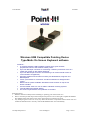
Wireless USB Compatible Pointing Device
Type-Matic On Screen Keyboard software
Features:• A compact Wireless USB compatible joystick which gives accurate
proportional control of the windows mouse pointer.
• 6 pin mini DIN input connector for connecting 5 switch input devices such as a
TASH mini joystick or Star switch (Optional).
• 6 pin mini DIN output connector for interfacing to an environmental control or
communication aid (Optional).
• Supports standard mouse button functions plus DoubleClick, DragLock and
MouseSpeed.
• 3.5mm jack sockets for connection of external switches for left/right button
control.
• Different knob options available. Standard unit has a switch on top for left
button activation.
• Can be located close to a user or fitted to standard mounting systems.
• Internal NiMH rechargeable battery.
• On Screen keyboard with word prediction is included
Important Notes:
1. Read this manual carefully before installing or operating your Point-It! Wireless.
2. Due to continuos product improvement Unique Perspectives reserves the right to update this Manual.
This Manual supersedes all previous issues which must not continue to be used.
3. Any attempt to gain access to or in any way abuse the electronic components of the Point-It! Wireless
renders the manufacturer’s warranty void and the Manufacturer free from liability.
©Unique Perspectives
www.click2go.ie
Page 1 of 30
User Manual
Jan 2005
wireless
Contents
Page
3
1.
Introduction
2.
Specifications
6
3.
Installation, Battery Charging + Test
7
4.
Operation
9
5.
Type-Matic Software
15
15
15
17
Installing the software
Running the program
Editing the layout
6.
Connections
23
7.
Maintenance
27
8.
Safety and Misuse warnings
28
9.
Warranty
29
10. Sales and Service Information
©Unique Perspectives
www.click2go.ie
30
Page 2 of 30
User Manual
wireless
Jan 2005
1 Introduction
Point-It! Wireless
Point-It! Wireless is a compact battery powered wireless USB compatible joystick
for use as an alternative to a mouse input. It gives smooth accurate proportional
control of a Windows mouse pointer. This small unobtrusive unit can be located
close to a user or mounted on their wheelchair. In addition it has fixings in its
base so that it can be attached to a Universal Mounting System and positioned
effectively for chin control. The joystick is a professional non-contacting type as
found on powered wheelchairs and is available with different knob options
including ball, chin, T-bar and sponge.
Three buttons are used to operate mouse functions left click, right click and
mouse speed. The function of the right button can be set to be either right click,
double click, drag lock or it can be used to switch between operating the mouse
and operating an external device (read below). A fifth switch located in the top of
the standard knob also operates the left button.
Advanced Modes
(NEW)
The Point-It! can also be operated in two advanced modes: “Joystick+Switch”
and “Joystick Only” modes.
In “Joystick+Switch” mode pressing the left button begins selection of a mouse
button action. Then, rather than moving the mouse pointer, the next movement of
the joystick makes a mouse button action. A left movement for left click, a right
movement for right click , a forward movement for a double click and a
backwards movement for a left drag lock. This mode is a good solution for a
person who can activate only one button but who requires all mouse functions.
In “Joystick Only” mode all mouse button actions can be selected without ever
pressing a button. For a left click the joystick is “flicked” to the left. For a right
click the joystick is “flicked” to the right. For a double click the joystick is “flicked”
forward and for a drag lock the joystick is “flicked” backwards (chooses external
device when option fitted).
See chapter 4 for a complete description of these advanced modes.
Using external switches and switch joysticks
For those who find it difficult to operate the buttons on the unit itself 3.5mm jack
sockets allow connection of standard switches
©Unique Perspectives
www.click2go.ie
Page 3 of 30
User Manual
wireless
Jan 2005
For those who prefer to use a switched joystick such as a TASH mini joystick,
Star switch or equivalent a special version of the unit is available. This unit has a
6 pin mini DIN switch input socket and no joystick. This enables a user to have
wireless control of a computer mouse from any 5 switch device.
Interfacing to communication aids and environmental controls (optional)
The Point-It! Wireless can be interfaced to any device that can already be
controlled by one or more switches. The joystick movements simply replace the
action of pressing switches. This enables a user to have integrated control over
both their computer mouse and an external device such as a communication aid
or environmental control from the same joystick. If the external device presents a
grid of options to the user, such as a symbol based communication aid, then
forward/back and left/right movements can be used to highlight an individual cell
in the grid whilst pressing the left button will select and activate the cell.
Switching between devices is achieved by one of three methods. By pressing
and holding the left switch for 4 seconds or by “flicking” the joystick backwards or
by pressing the right switch (refer to text later in this manual).
Interface cables are available for popular environmental control and
communication aid devices.
USB Mouse Emulator
The Point-It! Wireless is supplied with a mouse emulator. This plugs into the USB
port of your computer. When the Point-It! Wireless is positioned close to the
emulator an invisible link is made between the joystick and the computer.
The link is IrDA InfraRed with a range of up to 3 metres and a spread of ±45°.
The benefits of InfraRed are that more than one unit can be used in the same
room with no interference or compatibility problems and that the joystick is not
restricted to working with just one computer. In addition the mouse emulator is
available separately so that you can have wireless control of a computer at home
and in the workplace.
A PS2 version is available for older computers.
Type-Matic
Type-Matic is the On-Screen Keyboard software designed to be used in
conjunction with Point-It! Wireless PC Joystick. It enables people who cannot use
an ordinary computer keyboard to input text into any Windows® program!
A layout of cells represents the keys of a keyboard. When the mouse pointer is
positioned over a cell and the left button is clicked the key the cell contains is
sent to the active program.
©Unique Perspectives
www.click2go.ie
Page 4 of 30
User Manual
wireless
Jan 2005
Advanced word prediction features speed up the typing process. As you type
Type-Matic predicts not only the word you are typing but also the next word!
Abbreviations are also used so that commonly used phrases can be typed
quickly, for example, type “hau” and get “How are you”.
The Type-Matic layout is completely configurable. Colours, fonts, grid size etc.
can all be easily edited. Each cell can have its own key, colour, picture and help
text. Type-Matic can be fully customized to suit different users and comes with a
number of practical layouts to get you started straight away.
Windows® 98, ME, NT, 2000 & XP
©Unique Perspectives
www.click2go.ie
Page 5 of 30
User Manual
Jan 2005
wireless
2 Specifications
Electrical
Power Supply
170mAH 9V Nickel Metal Hydride
rechargeable internal battery
<20mA
External 60mA wall cube
Quiescent Current
Charger
Mechanical
Weight
Case material
Approx. 500grams
Extruded aluminum, painted black.
Environmental
Operating ambient temperature range
Storage temperature range
Operating and storage humidity
Min
Max
Units
-25
-25
0
50
70
90
ºC
ºC
%RH
The Point-It! Wireless is not designed for outdoor use.
Intended Use
The Point-It! Wireless is a USB compatible pointing device designed to enable
those individuals who cannot use a standard computer mouse the ability to
manipulate the windows mouse pointer.
The Point-It! Wireless is for indoor use only.
The Point-It! Wireless in conjunction with the mouse emulator can only be
connected to a PC with a USB port.
©Unique Perspectives
www.click2go.ie
Page 6 of 30
User Manual
Jan 2005
wireless
3 Installation, Battery fitting + Test
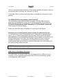
Mounting
Most users will not need a mount at all and be able to operate the joystick on a
tray or in their lap. However for some users a mount will be required, for example
a chin joystick user or those with gross motor movements.
NOTE: The Point-It! is available in 2 styles: standard and ball. The ball knob on
can be interchanged with various other knobs. See page 10. The knob on the
standard version cannot be changed because of the wiring to the switch.
The Point-It! Wireless can be mounted on a goose neck arm or suitable mounting
kit using M4 screws. The choice and construction of the mount will depend upon
the user’s needs.
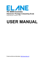
Warning !! For safe installation, select a screw length between 6mm and 10mm.
Dimensions of the mounting Position is shown below:AbleNet Jellybean switch mounting plate
Super Mount
2.5inc
hes
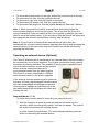
Charging the internal battery
When the battery is low the unit will beep twice every 15 seconds when it is on
and unattended. As a rule of thumb it is advised to give the battery a full
charge once a week. The Point-It! Wireless is supplied with the internal battery
fully discharged
To charge the battery
1. Plug the charger supplied into a mains socket
2. Connect the charger to the Point-It! Wireless.
3. Confirm that the red light on the charger is illuminated
The battery is a Nickel Metal Hydride type and does not suffer from memory
effect. This means that it can be “topped up” rather than waiting for the battery to
©Unique Perspectives
www.click2go.ie
Page 7 of 30
User Manual
wireless
Jan 2005
be completely flat before recharging. The battery should become fully charged
after 10hours.
NOTE: It is not possible to use the Point-It! Wireless when it is on charge
(plugging in the charger turns the Point-It! Wireless off).
Replacing the rechargeable battery
With normal use the battery should never need to be changed and is rated for
800 charge cycles. However if the battery becomes faulty or fails to retain its
charge it may need to be replaced (contact your supplier for the correct type).
1. Remove the 2 plastic screw caps at
the front of the Point-It! Wireless
with the flat end of the screw driver
supplied or with a finger nail or pin
(note the back of the unit is the
connector panel, the front has a
shiny black surface).
2. Remove the 2 screws and gently
remove the InfraRed module taking
care not to put any strain on the
cable linking the module to the
internal circuit board. Under no
condition should you attempt to disconnect it.
3. Slid the battery into the unit with the battery connections facing outwards and
then press the battery clip into position.
4. Confirm that the unit is working by pressing the left button. The unit should
beep.
5. Finally put the InfraRed module back into position taking care not to get any
wires caught in the casing and replace the screws and screw caps.
Testing - Power On check sequence
1.
2.
3.
4.
Make sure your computer is off.
Connect the mouse emulator to the USB port of your computer.
Switch on your computer.
When Windows® is running confirm that green LED at the front of the
emulator is blinking.
5. Press the Left button on the Point-It! Wireless to turn it on. The unit should
beep once (see note below).
6. Position the Point-It! Wireless in front of the emulator and confirm that the
green LED stops blinking and that the joystick is moving the mouse.
NOTE: If the green LED does not stop blinking the Point-It! Wireless may be in
external mode. Press the right button to return to mouse mode and try again.
©Unique Perspectives
www.click2go.ie
Page 8 of 30
User Manual
Jan 2005
wireless
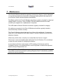
4 Operation
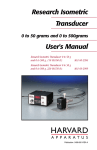
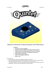
Refer to the following diagram when reading the operating instructions:Mouse Speed
and Operating
Mode select.
Hold down any left
button for 4 seconds to
switch between
controlling the mouse
and controlling an
external device (unless
operating mode 4 or 6
is selected – see text
below).
1. Deflect the joystick
forward for Mode 1
2. Deflect the joystick right
for Mode 2
3. Deflect the joystick down
for Mode 3
4. Deflect the joystick left for
Mode 4
5. Press the Left button for
Mode 5
6. Press the Right button for
Mode 6
Charger socket.
Left button switch
input (also disables
switch on knob).
To select the operating mode
press and hold the white
button for 10 seconds until
the unit beeps.
Right button
switch input.
5 Switch output to
communication aid or
environmental control.
(Optional Extra)
Turning on the Point-It! Wireless
To turn on the Point-It! Wireless press the Left Button. The unit will beep once if
in mouse mode or twice if in external mode.
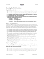
Setting the Operating Mode
There are six modes. Four standard modes and two advanced modes.
To set the Operating Mode:
1. Press and hold the white speed button for ten seconds until the unit beeps
2. Deflect the joystick forward to select Mode 1
3. Deflect the joystick right to select Mode 2
4. Deflect the joystick back to select Mode 3
5. Deflect the joystick left to use the Mode 4
6. Press the Left button to select Mode 5
7. Press the Right button to select Mode 6
8. The Point-It! Wireless will emit 1 or more beeps indicating the mode you
have chosen.
NOTE: It is not intended that the user will set the Operating Mode during normal
use. Typically this will be set just once when the joystick is first installed. The
selection will depend on the user’s needs and abilities.
©Unique Perspectives
www.click2go.ie
Page 9 of 30
User Manual
wireless
Jan 2005
Operating the Point-It! wireless
Standard Modes (1 – 4)
• To move the mouse pointer up the screen deflect the joystick knob forward.
• To move the mouse pointer down the screen deflect the joystick knob back.
• To move the mouse pointer to the left, deflect the joystick knob to the left.
• To move the mouse pointer to the right, deflect the joystick knob to the right.
• To generate a left click, click the left button.
• Depending on the operating mode the right button can be used to generate
one of the following mouse functions:
In mode 1
Right Click
In mode 2
Left Double Click
In mode 3
Left Drag Lock
In mode 4
Direct switch between mouse control a nd external device
Mode 5 - “Joystick+Switch”
In “Joystick+Switch” mode pressing the left button begins selection of a mouse
button action. Then, rather than moving the mouse pointer, the next movement of
the joystick makes a mouse button action. This mode is a good solution for a
person who can activate only one button but who requires all mouse functions.
•
•
•
•
•
•
•
•
To move the mouse pointer up the screen deflect the joystick knob forward.
To move the mouse pointer down the screen deflect the joystick knob back.
To move the mouse pointer to the left, deflect the joystick knob to the left.
To move the mouse pointer to the right, deflect the joystick knob to the right.
To generate a left click, click the left button (the unit will beep) and then
deflect the joystick to the left.
To generate a right click, click the left button (the unit will beep) and then
deflect the joystick to the right.
To generate a left double click, click the left button (the unit will beep) and
then deflect the joystick forward.
To generate a left drag lock, click the left button (the unit will beep) and then
deflect the joystick backwards.
Mode 6 - “Joystick Only”
In “Joystick Only” mode all mouse button actions can be selected without ever
pressing a button. This is achieved by flicking the joystick in a particular direction
to generate the desired mouse button function. This mode is a good solution for a
person who can only move the joystick.
•
•
•
To move the mouse pointer up the screen deflect the joystick knob forward.
To move the mouse pointer down the screen deflect the joystick knob back.
To move the mouse pointer to the left, deflect the joystick knob to the left.
©Unique Perspectives
www.click2go.ie
Page 10 of 30
User Manual
•
•
•
•
•
wireless
Jan 2005
To move the mouse pointer to the right, deflect the joystick knob to the right.
To generate a left click, flick the joystick to the left.
To generate a right click, flick the joystick to the right.
To generate a left double click, flick the joystick forward.
To generate a left drag lock, flick the joystick backward (See note 2 below).
Note 1: When you move the joystick, there will be a short delay before the
mouse pointer begins to move on the screen. This is because the Point-It! is
trying to determine if you are making a flick of the joystick or whether you really
want to move the mouse pointer. It you do make a flick the Point-It! will beep and
then generate the chosen mouse button function (see list above).
Note 2: If your Point-It! is fitted with the external device option then the
backwards flick is used to switch between operating the mouse and operating the
external device. In this case a left drag lock function can still be achieved by
pressing the left button.
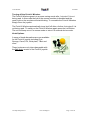
Operating an external device (Optional)
The Point-It! Wireless can be interfaced to any external device that can already
be controlled by one or more switches. The joystick movements simply replace
the action of pressing switches. This enables a user to have integrated control
over both their computer mouse and an external
device such as a communication aid or
environmental control from the same joystick.
The Point-It! is shown interfaced to a GEWA
environmental control in the picture opposite.
If the external device presents a grid of options to
the user, such as a symbol based communication
aid, then forward/back and left/right movements
can be used to highlight an individual cell in the
grid whilst pressing the left button will select and
activate the cell.
Standard Modes (1 – 4)
To switch from mouse control to controlling an external device…
1. With the exception of mode 4 press and hold the left button for four
seconds, whilst not moving the joystick, until the unit beeps. The joystick
will switch to controlling the external device.
In mode 4 press the right button. The unit will beep and the joystick will
switch to controlling the external device.
©Unique Perspectives
www.click2go.ie
Page 11 of 30
User Manual
wireless
Jan 2005
2. Use left/right and up/down deflections to highlight cells on the external
device. To make a selection press the left button.
To switch back to mouse control…
1. With the exception of mode 4 press and hold the left button for four
seconds until the unit beeps. The joystick will switch to controlling the
mouse.
OR
Press the right button. The unit will beep and the joystick will switch to
controlling the mouse (note that in mode 4 the only way to switch back to
mouse control is by pressing the right button).
Mode 5 – “Joystick+Switch”
To switch from mouse control to controlling an external device…
1. Press and hold the left button for four seconds, whilst not moving the
joystick, until the unit beeps. The joystick will switch to controlling the
external device.
OR
Press the right button. The unit will beep and the joystick will switch to
controlling the external device.
2. Use left/right and up/down deflections to highlight cells on the external
device. To make a selection press the left button.
To switch back to mouse control…
1. Press and hold the left button for four seconds until the unit beeps. The
joystick will switch to controlling the mouse.
OR
Press the right button. The unit will beep and the joystick will switch to
controlling the mouse.
©Unique Perspectives
www.click2go.ie
Page 12 of 30
User Manual
Jan 2005
wireless
Mode 6 – “Joystick Only”
To switch from mouse control to controlling an external device…
1. Make a backwards flick of the joystick OR press the right button. The unit
will beep and the joystick will switch to controlling the external device.
2. Use left/right and up/down deflections to highlight cells on the external
device. To make a selection flick the joystick to the left.
To switch back to mouse control…
1. Make a backwards flick of the joystick. The unit will beep and the joystick
will switch to controlling the mouse.
OR
Press the right button. The unit will beep and the joystick will switch to
controlling the mouse.
NOTE 1: When the unit switches itself off it will remember which mode it was in,
i.e. mouse mode or external device mode. When the unit is switched on again it
will beep once if in mouse mode or twice if in external access mode.
NOTE 2: If the Point-It! Wireless is not supplied with a Switch output
connector it will not switch into external device mode.
NOTE 3: In external device mode the link to the mouse emulator is disabled and
the green light will start blinking. DO NOT CONFUSE THIS WITH THE
JOYSTICK BEING OUT OF RANGE, IN STANDYBY OR SWITCHED OFF.
Mouse Speed
The mouse speed can be set to one of three values. Slow, Medium and Fast.
When the Point-It! Wireless is turned on for the first time it is set to Medium
speed. To change the mouse speed press the white button once. Point-It!
Wireless will change speed to the next setting and beep once to indicate slow
speed, twice to indicate medium speed or three times to indicate fast speed.
TIP: For users with gross motor movements set the Point-It! to the slowest speed
and allow the user to use the full deflection of the Joystick. The joystick contains
a diamond shaped restrictor plate that helps a user locate the stick in one of four
directions and hold it there.
©Unique Perspectives
www.click2go.ie
Page 13 of 30
User Manual
wireless
Jan 2005
Turning off the Point-It! Wireless
The Point-It! Wireless goes into a power saving mode after 1 minute if it is not
being used. In this mode the link to the mouse emulator is disabled and the
green light on the emulator will start blinking. To re-enable the Point-It! Wireless
simply move the joystick.
The Point-It! Wireless automatically turns itself off after a further 4 minutes if it is
not being used. To switch on the Point-It! Wireless again press the Left Button.
The unit will beep once if in mouse mode or twice if in external device mode.
Knob Options
A range of knob alternatives are now available
for the Point-It! joystick including Chin,
Sponge, Carrot, DX, Wrist plate, T-Bar and
more.
These knobs are only inter-changeable with
the Ball Knob version of the Point-It! joystick.
©Unique Perspectives
www.click2go.ie
Page 14 of 30
User Manual
5
wireless
Jan 2005
TypeMatic Software
Installing the Software
1. Insert the CDROM into your CD-ROM drive
2. If the installation program does not “autorun” then choose ‘Run’ from the
Windows Start menu and continue with step 3, otherwise jump to step 5.
3. Type d:\setup.exe. (if your CD-ROM drive is not drive D, type the appropriate
letter instead.)
4. Choose OK.
5. Follow the instructions on the screen.
Running the Program
Run TypeMatic by choosing Programs from the Start menu and clicking on the
TypeMatic icon.
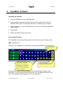
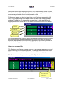
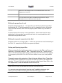
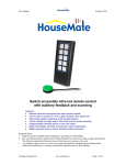
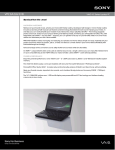
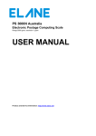
When you run TypeMatic for the first time the following default Grid is presented:Standard keyboard
keys.
5 Special keys. Spacebar,
Backspace, Enter, Shift and
SentenceBar. To view help text
on a character position the
mouse over the cell and pop-up
help text will appear.
Links to other grids for numbers,
punctuation and function keys.
Now launch a word processing program such as WordPad and open a new
document. To type, position the mouse pointer over the desired character and
click. The character should appear in your new document.
©Unique Perspectives
www.click2go.ie
Page 15 of 30
User Manual
wireless
Jan 2005
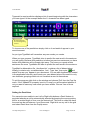
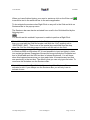
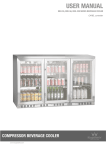
Typematic’s word prediction displays a list of words beginning with the characters
you have typed. In the example below the ‘h’ character has been typed.
Word predictions
for word beginning
with ‘h’.
To choose one of the predictions simply click on it and watch it appear in your
word document.
As you type TypeMatic will remember any new words you create.
When you type a space, TypeMatic tries to predict the next word in the sentence
you are typing. Because this prediction is based on previous sentences you have
written this prediction will not begin right away. The more you repeat certain
sentences the more TypeMatic will learn to predict the next word in the sentence.
TypeMatic’s abbreviation file, ‘shorthand.txt’, contains a list of abbreviations.
Initially it contains only one abbreviation, ‘hau’. Type ‘hau’, then enter
and
watch ‘How are you’ appear in your document. You can edit shorthand.txt located
in the application directory and create your own abbreviations. Be careful to only
use character groupings which do not constitute a word in themselves.
To quit the program right click on the window and choose ‘Exit’ from the Pop-Up
menu. If the ‘UpdateFile’ property is set to ‘Prompt’ you will be asked whether or
not you want to save any new words you have written. Choose Yes or No as
required.
Setting the Dwell time
For users who are unable to use Left or Right click buttons a Dwell feature is
provided whereby a cell is automatically selected by keeping the mouse pointer
still for a certain length of time over the desired cell. This time is called the dwell
time and can be set between 1 and 5 seconds. Right click on any cell in the grid
and select Dwell time from the PopUp menu.
©Unique Perspectives
www.click2go.ie
Page 16 of 30
User Manual
Jan 2005
wireless
Now when you position the mouse pointer over a cell and keep it still for dwell
time the contents of the cell will be typed into the active application, i.e. the cell is
automatically selected without having to make a click.
Furthermore when you select a Dwell time a set of buttons representing Left
click, Left Drag and Right click appear in the left hand side of the TypeMatic
window. These allow you to generate mouse clicks in other applications by
keeping the mouse pointer still for the dwell time over the control you want to
click.
Left Click
Left Dbl Click
Left Drag
Right Click
First select the mouse click you want to generate by keeping the mouse pointer
still over the button representing the desired mouse click. After the button is
selected (down position) move the mouse pointer over the control you want to
click in the other application and keep it still for the dwell time.
Using the Sentence Bar
The Sentence Bar feature allows a user you to pre-prepare a sentence or word
before sending it to the active application. To activate the sentence bar Right
Click on any cell in the grid and click on Sentence Bar in the pop-up menu.
The Sentence bar will appear at the top of the TypeMatic window.
Special key also
activates the
sentence bar.
©Unique Perspectives
www.click2go.ie
Page 17 of 30
User Manual
Jan 2005
wireless
When you have finished typing your word or sentence click on the Enter cell
to send the text in the sentence bar to the active application.
To de-activate the sentence bar Right Click on any cell in the Grid and click on
Sentence Bar in the pop-up menu.
The Sentence bar can also be activated from a cell in the Grid identified by the
following icon:
You would use this method if a person is unable to perform a Right Click.
Note: If this cell does not appear in the Grid you are using, but you require it,
then you must edit the Grid and create a cell with the “Key” property set to
“SENTENCE_BAR”. This is one of the special keys selected from the drop
down list. See the following page on how to edit the cells in the Grid.
In Windows 2000 and Windows XP it is not possible to input text letter by letter
into certain text boxes. Examples of these text boxes include the FileName text
box in WordPad® and the URL text box in Internet Explorer®. You will know
when this happens because as you type each letter it overwrites any text that
was previously in the text box. The result is that you can only type one letter. To
overcome this limitation use the Sentence Bar.
Note: When you close TypeMatic it will remember if the Sentence Bar was
activated or not. If you always use the Sentence Bar you will only have to
activate it once.
©Unique Perspectives
www.click2go.ie
Page 18 of 30
User Manual
Jan 2005
wireless
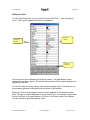
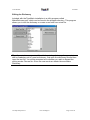
Editing the Grid
To edit a Grid right click on any cell and choose ‘Edit Grid…’ from the pop-up
menu. The Layout properties window is presented.
Property
values
Property
names
Property
help text
The left hand column displays the property names. The right hand column
displays the property values. The panel at the bottom of the window displays the
properties help text.
To view the help text of a property click on the property name. The help text for
the property appears in the panel at the bottom of the window.
When you click on the property name a control appears in the property value
field. The type of control depends on the property type, for example a drop down
list for Grid Size, a file open button for Picture, a text entry control for Caption.
Use the control to edit the property value.
©Unique Perspectives
www.click2go.ie
Page 19 of 30
User Manual
wireless
Jan 2005
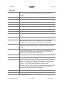
Properties
Layout
You can have any number of grids with TypeMatic. Click the FileSave
button to save the current Grid or click the FileOpen button to open
another.
BackColor
The color of the background.
BevelStyle
The bevel style of cells in the grid. Can be set to none, Inset or Raised.
BevelWidth
The width of a cell bevel. Can be set between 1 and 8.
CellGap
The gap between cells. Can be set between 0 and 8.
CellSize
The size of the cells in the grid. Can be set to 16x16, 32x32 or 64x64.
Font
The font used throughout the grid.
GridPosition
The start-up position of the grid on the screen.
GridSize
The size of the grid. The smallest size is 4x4 cells, the largest is 8x10
cells.
HighlightColor
The color used to highlight cells.
Abbreviations
Specifies whether or not the abbreviation feature is enabled. The
abbreviation list is stored in the file ‘shorthand.txt’ in the application
directory. You can edit it to add more abbreviations using notepad.
WordPrediction
The type of word prediction used. Can be set to none, current word or
current plus next word. When set to none the word prediction column is
hidden.
UpdateFile
Specifies how the word prediction file ‘typematic.dic’ is updated with the
words written and chosen by a user. Can be set to Always, Never or
Prompt. If set to prompt the user is asked whether or not they wish to
save any new words when they quit the program.
*CellColor
The color of a cell. If the cell is transparent this property has no effect.
*FontColor
The color of the font in the cell.
*Key
The key(s) to be pressed (simulated) when the cell is selected. Use ‘+’ for
SHIFT, ‘%’ for ALT and ‘^’ for CTRL. These special keys have a toggle
function. To specify an actual plus sign use ‘{+}’. For ‘^’ use ‘{^}’, for ‘%’
use ‘{%}’. You can select other special keys from the listbox.
Note than when you select a key the text is automatically assigned to the
caption. You can have the caption text different from the key text but
always set the key text first, then the caption text.
*Caption
The text that appears in the cell.
*HelpText
The help text for the cell which will be displayed when the mouse is
paused over the cell.
©Unique Perspectives
www.click2go.ie
Page 20 of 30
User Manual
Jan 2005
wireless
*Transparent
Specifies whether or not a cell is transparent. A transparent cell takes on
the color of the background when not selected and the color of the
highlight when selected.
*Picture
Each cell can contain a picture (bitmap or icon only).
*NextGrid
You can link a cell to another grid by specifying the file here. In this way
you can have links to grids of numbers and punctuation. Always
remember to have a link back to the main grid!
Editing the properties of a cell
Properties beginning with an ‘*’ are specific to an individual cell and only effect
the selected cell. To edit the property of a cell, for example it’s key, click on the
cell in the main window, then click the property name called ‘key’ and edit it’s
content.
A special case is the column of word predictions. These cells have the same
properties. In other-words if you set the cell color for a word prediction cell it
effects all word prediction cells.
Editing the ‘general’ properties of the Grid
Properties which do not begin with a ‘*’ effect the general look and functionality of
the Grid. For example the GridSize is a general property.
Saving and Opening layout files
When you have finished editing properties you can save the Grid as a file on your
hard disk. The files are called ‘tlf’ files: ‘Typematic Layout File’. To save a Grid
click on the first property called ‘layout’. A File Open and File Save button appear
in the property value field. Click the File Save button to save your newly edited
Grid.
Typematic comes with a selection of files to illustrate different Grids. These files
are called small.tlf, standard.tlf and colorful.tlf and are located in the application
directory. To load a Grid click on the first property called ‘layout’ then click on the
File Open button, locate the desired file and choose OK.
Note: When you close the Layout properties window TypeMatic will remember
which Grid is in use and will load this Grid the next time it is run.
You can also open grids directly from the main TypeMatic window by right
clicking on any cell and choosing Open Grid from the popup menu.
©Unique Perspectives
www.click2go.ie
Page 21 of 30
User Manual
wireless
Jan 2005
Editing the Dictionary
Included with the TypeMatic installation is a utility program called
MakeDictionary.exe which can be found in the program directory. This program
allows you to edit the dictionary or create a new one from a text file.
Tip: If you wish to merge a text file with the existing dictionary, for example to
add a vocabulary set to a user’s dictionary, first open the dictionary file and then
open the text file. You will be prompted as to whether you wish to discard the
exiting words. Choose No. Once the new words are loaded choose Make
Dictionary.
©Unique Perspectives
www.click2go.ie
Page 22 of 30
User Manual
wireless
Jan 2005
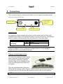
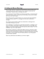
6 Connections
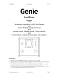
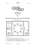
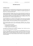
The connection panel is located at the back of the unit and is illustrated below.
Standard unit with external device option
Switch Outputs to
external device
(Optional)
Charger socket
Left button input
Right button input
Switch Inputs
For users who cannot operate the buttons on the joystick itself 2x3.5mm jack
sockets are provided on the connection panel. You can connect any non-latching
switch to these sockets provided they are fitted with 3.5mm jack plugs.
Connector
Standard 3.5mm
jack plug
Pin
Tip
Sleeve
Signal
Switch
Switch common
Note: When you insert a switch into the left socket the button at the top of the
joystick is disabled. This is a feature to enable people to use the standard
joystick knob but not the button at the top.
Fitting a 5 switch input device
For users who prefer to use a 5 switch
device such as a TASH mini joystick,
Star switch or equivalent a special
version of the unit is available with the
6 pin mini DIN switch input cable and
no joystick.
This unit is provided with a 6 pin mini
DIN to 9pin D interface cable. Plug the 5 switch device into the 9 pin D and then
plug the 6 pin mini DIN into the left hand side socket of the Point-It! Wireless.
NOTE: In this mode it is not possible to access the right button or the mouse
©Unique Perspectives
www.click2go.ie
Page 23 of 30
User Manual
Jan 2005
wireless
speed button from the five switch device.
The pin-out of the 6 pin mini DIN socket is shown below for those who wish to
make a special interface to the wireless joystick, for example a set of 5 discrete
switches set into a person’s tray.
6 pin Mini DIN.
Connector
1
2
3
4
5
6
Pin
1
2
3
4
5
6
Signal
Switch common
Mouse Left
Mouse Right
Mouse Down
Mouse Up
Left Button
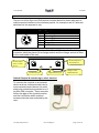
NOTE: When you order this version of the Point-It! Wireless the 5 switch input
connector takes the place of the charger socket and the charger socket is fitted
to the underneath of the unit.
Switch Outputs to
external device
Switch Inputs
from 5 switch
device.
Left button input
Right button input
Charger socket
underneath unit
Switch Outputs & Interfacing to other devices.
To connect the Joystick to an external
device such as a communication aid or
environmental control device five solid
state relay contacts are provided on a 6
pin Mini DIN connector. These contacts
reflect the state of the joystick position
and the Left Button when external
access mode has been selected by the
user.
©Unique Perspectives
www.click2go.ie
Page 24 of 30
User Manual
wireless
6 pin Mini DIN.
Connector
1
2
3
4
5
•
•
6
Pin
1
2
3
4
5
6
Jan 2005
Signal
Switch common
Joystick Left
Joystick Right
Joystick Down
Joystick Up
Left Button
relays are current rated to 250ma
contacts are isolated from wheelchair electronics
The interface to the external device will depend upon the number of switch inputs
and connector type available on the external device. Several different interface
options are described below:Devices with a 9 pin D switch input
If the external device is capable of being controlled by a five switch device such
as a TASH mini joystick, wafer pad or star switch then the device will have a 9
pin D switch input. With a 6 pin Mini DIN to 9 pin D cable the Genie joystick can
be connected to such devices and operated in exactly the same way as if the five
switch device were connected to it. The pinout of the 9pin D is shown below:
Connector
9 Pin Male D
Pin
1
2
3
4
5
6
7
8
9
Signal
Forward (Switch 2)
Backwards (Switch 3)
Left (Switch 4)
Right (Switch 5)
Select (Switch 1)
Switch common
A 6 pin Mini DIN to 9 pin D cable is available for connection to devices with this
type of switch input.
Devices with 3.5mm jack switch inputs
Unfortunately most communication aid devices have only 2x3.5mm switch inputs.
In this case the joystick can be wired to the device so that a forward deflection of
the joystick activates the switch 1 input of the external device (normally the
©Unique Perspectives
www.click2go.ie
Page 25 of 30
User Manual
wireless
Jan 2005
“select”) and a backwards deflection of the joystick activates the switch 2 input of
the external device (normally the “advance” or “step”).
A 6 pin Mini DIN to 2x3.5mm jack plug cable is available for connection to such
devices.
The GEWA PROG environmental control interface
The switch input of the GEWA PROG III is also a 6 pin Mini DIN connector
whose pin-out matches that of the Point-It! Wireless joystick. To operate the
PROG from the joystick it is necessary to put the PROG in joystick input mode.
You can do this by pressing “P+5”, followed by “1” on the PROG. Consult the
PROG manual for further details.
A pin-to-pin Mini DIN cable is available for connection to this device
Interfacing to an environmental control unit and a communication aid.
To interface to more than 2 external devices it is necessary to operate both of
them in a 1 or 2 switch mode as per “Devices with 3.5mm jack switch inputs”
described above. Use forward/back deflections of the joystick for one device and
left/right deflections for the other. An interface cable for this kind of setup is
available on request. It is important to note however that as most modern
communication aids have a built in environmental control unit, or the option of it,
this type of setup is rarely required.
NOTE: The 5 switch output connector is not fitted as standard. You must specify
that you want this feature when ordering.
USB Cable (on the Mouse Emulator)
The USB Cable is a standard cable that is connected to the USB port of your
computer. If your computer supports the older PS2 mouse connector contact
your supplier for a PS2 version.
©Unique Perspectives
www.click2go.ie
Page 26 of 30
User Manual
Jan 2005
wireless
7 Maintenance
The Point-It! Wireless should be regularly checked for integrity. Loose, damaged
or corroded connectors or terminals, or damaged cabling should be reported to
your Service Centre and be replaced immediately.
The Battery within the Point-It! Wireless should be regularly checked for chemical
leakage and/or corrosion. Only 9v NiMH 170mAH batteries should be used
(contact your supplier for a replacement if required).
The USB cable of Mouse Emulator should be regularly checked for integrity.
All switches connected to the Point-It! Wireless should be regularly tested to
ensure that they function correctly.
The Point-It! Wireless should be kept free of dust, dirt and liquids. If necessary
wipe with a cloth dampened with warm water or alcohol. Do not use solvents or
abrasive cleaners.
Where any doubt exists, consult your nearest Service Centre or Agent.
There are no user-serviceable parts within the Point-It! Wireless. Do not attempt
to open the case except for changing the battery.
In accordance with the requirements of CE marking of this device and the
Company’s policy, it is requested that re-occurring faults or defects be reported
back to Unique Perspectives Ltd.
Warning !! If the Point-It! Wireless is damaged in any way, or if internal damage
may have occurred (for example by being dropped), have it checked by qualified
personnel before operating.
©Unique Perspectives
www.click2go.ie
Page 27 of 30
User Manual
Jan 2005
wireless
8 Safety and Misuse Warnings
Do not install, maintain or operate the Point-It! Wireless without reading and
understanding the user manual and that of the computer to which you are
connecting to, otherwise injury or damage may result.
Do not operate the Point-It! Wireless if it behaves erratically, or shows abnormal
response, heating, smoke or arcing. Remove the battery, disconnect all cables,
and consult your service agent.
Ensure that your PC is turned off when not in use and never leave the Mouse
emulator and associated PC on or plugged into the mains unattended or
overnight.
No connector pins should be touched, as contamination or damage due to
electrostatic discharge may result.
Point-It! Wireless is not designed to resist water penetration. If a spillage occurs
remove the battery, disconnect all cables, and consult your service agent. Any
spillage over the Point-It! Wireless should be wiped dry without delay. The PointIt! Wireless may not be used outdoors.
Most electronic equipment is influenced by Radio Frequency Interference (RFI).
Caution should be exercised with regard to the use of portable communications
equipment in the area around such equipment. While the manufacturer has made
every effort to ensure that RFI does not cause problems, very strong signals
could still cause a problem.
Report any malfunctions immediately to your Service Agent.
©Unique Perspectives
www.click2go.ie
Page 28 of 30
User Manual
wireless
Jan 2005
9 Warranty
All equipment supplied by Unique Perspectives Ltd. is warranted by the company
to be free from faulty materials or workmanship. If any defect is found within the
warranty period of 12 months, the company will repair the equipment, or at its
discretion, replace the equipment without charge for materials and labor.
The warranty is subject to the conditions that the equipment:
•
Has been used solely in accordance with this manual.
•
Has not been subjected to misuse or accident, or been modified or repaired
by any person other than someone authorised by Unique Perspectives Ltd.
•
Has been used solely for the use of alternative mouse input.
©Unique Perspectives
www.click2go.ie
Page 29 of 30
User Manual
Jan 2005
wireless
10 Sales and Service Information
For Sales and Service advice, or in case of any difficulty, please contact:
Unique Perspectives Ltd.
Ballyclovan
Callan
Kilkenny
Ireland
Telephone:
Fax:
+353 56 7725913
+353 56 7725936
WEB: www.click2go.ie
EMAIL: [email protected]
NOTE: The Point-It! Wireless should be clearly labeled with the manufacturer’s
service agent’s telephone number.
©Unique Perspectives
www.click2go.ie
Page 30 of 30