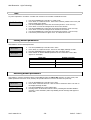
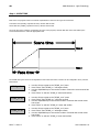
1
SGM Elettronica - Light Technology GB Summary Summary...........................................................................................................................2 Palco .................................................................................................................................5 Safety information.................................................................................................................6 General Warranty Conditions .................................................................................................6 Main Features .......................................................................................................................7 LEDs ............................................................................................................................................7 Lenses .........................................................................................................................................7 Functions .....................................................................................................................................7 Control signals ..............................................................................................................................7 Microcomputer..............................................................................................................................8 Introduction .....................................................................................................................9 Regarding this Manual ...........................................................................................................9 Manual symbols ....................................................................................................................9 Palco functions.................................................................................................................... 10 USITT DMX 512 ..........................................................................................................................10 Cooling.......................................................................................................................................10 Colour ........................................................................................................................................10 LEDs ..........................................................................................................................................10 Dimmer......................................................................................................................................10 Shutter.......................................................................................................................................10 Macro ........................................................................................................................................11 Memories ...................................................................................................................................11 Display.......................................................................................................................................11 Software Update .........................................................................................................................11 Specifications...................................................................................................................... 12 Mechanical .................................................................................................................................12 Electrical ....................................................................................................................................12 Lenses .......................................................................................................................................13 LEDs ..........................................................................................................................................13 Optional Accessories............................................................................................................ 13 Control panel ...................................................................................................................... 13 Installation .....................................................................................................................14 Unpacking .......................................................................................................................... 14 Mounting the fixture ............................................................................................................ 14 Wiring ........................................................................................................................................14 Installation and positioning ..........................................................................................................15 Addressing the fixture .................................................................................................................17 Operation ........................................................................................................................20 Controlling the fixture via DMX............................................................................................. 20 Dimmer Channel Ch 2..................................................................................................................20 Red Channel Ch 3 .......................................................................................................................20 Green Channel Ch 4 ....................................................................................................................20 Blue Channel Ch 5.......................................................................................................................20 Strobe/Shutter Channel Ch 1........................................................................................................21 Macro Channel Ch 7 ....................................................................................................................21 Colour Mode Channel Ch 8...........................................................................................................22 CTC Channel Ch 6 .......................................................................................................................22 User's manual 1.01 -2- Palco 3 - Palco 5 GB SGM Elettronica - Light Technology Operation ........................................................................................................................... 22 Colours ......................................................................................................................................22 Colour temperature .....................................................................................................................23 Shutter/Strobe ............................................................................................................................23 Menus .............................................................................................................................24 Addressing.......................................................................................................................... 25 Colour Balance .................................................................................................................... 25 Balance .............................................................................................................................. 25 Boost.................................................................................................................................. 26 Elapsed time meter .............................................................................................................26 Input signal ........................................................................................................................ 26 Display brightness ............................................................................................................... 27 Invert display...................................................................................................................... 27 DMX delay .......................................................................................................................... 27 Days of the week ................................................................................................................ 27 Time .................................................................................................................................. 28 Setting default parameters................................................................................................... 28 Resetting default parameters ............................................................................................... 28 Test functions ..................................................................................................................... 29 Head temperature ...............................................................................................................29 Configuring a Master ...........................................................................................................29 Configuring Slaves............................................................................................................... 30 Enabling – Disabling the Scheduler....................................................................................... 30 Internal program playback ................................................................................................... 30 Programmer........................................................................................................................ 31 Scheduler ........................................................................................................................... 31 Stand-alone Programming .............................................................................................32 Programming PALCO ........................................................................................................... 32 Step Step Step Step Step Step Step Step Step Step Step Step Step 1 - CHOOSING THE PROGRAM NUMBER ................................................................................32 2 - CHOOSING THE SCENE NUMBER .....................................................................................33 1 - CHOOSING THE FIXTURE NUMBER ..................................................................................33 4 - SHUTTER.......................................................................................................................33 5 - DIMMER ........................................................................................................................33 6 - RED...............................................................................................................................34 7 - GREEN...........................................................................................................................34 8 - BLUE .............................................................................................................................34 9 - MACRO ..........................................................................................................................34 9 - SCENE TIME...................................................................................................................35 10 - FADE TIME...................................................................................................................36 11 – ENABLING SCENES.......................................................................................................36 12 - PROGRAM PLAYBACK ....................................................................................................37 Palco 3 - Palco 5 -3- User's manual 1.01 SGM Elettronica - Light Technology GB The Event Scheduler ........................................................................................................... 37 Step Step Step Step Step Step Step 1 2 3 4 5 6 7 - CHOOSING THE EVENT NUMBER .....................................................................................37 - CHOOSING the PROGRAM number...................................................................................37 - CHOOSING THE DAY ......................................................................................................38 - START TIME..................................................................................................................38 - END TIME .....................................................................................................................39 – ENABLING AN EVENT .....................................................................................................39 – ENABLING THE SCHEDULER ...........................................................................................39 Maintenance ...................................................................................................................40 Ordinary maintenance .................................................................................................................40 Special maintenance....................................................................................................................40 Accessories .....................................................................................................................41 Installing optional lenses .....................................................................................................41 Removing the front lens panel......................................................................................................41 Installing the new front lens panel................................................................................................43 User's manual 1.01 -4- Palco 3 - Palco 5 GB SGM Elettronica - Light Technology Palco Palco automated fixtures are the result of the design philosophy that all SGM products have had in common for years. The accurate study of their functions, search for innovative materials and on-going technical updating, have led to the manufacture of this unique product. In fact, Palco is the first intelligent fixture of the SGM range based on LED emitter technology. Palco units are fixtures suited to a multitude of applications in the entertainment and decorative/architectural lighting fields. Long life, balanced mixing of all colour ranges, weather resistance, user-friendly programmability and innovative design make Palco an avant-garde products of its type at world level. Palco units are built in compliance with current CE norms. Thanks for having chosen a fixture from the SGM Palco 3 and 5 series. Palco 3 - Palco 5 -5- User's manual 1.01 SGM Elettronica - Light Technology GB Safety information Read the instructions in this manual carefully, as they give important instructions regarding installation, operation and maintenance safety. This manual must be kept with the fixture for future consultation. In the event of the fixture being sold or passed to another user, always make certain that the booklet is with the unit, to enable the new owner to be informed on its operation and relative care. ¨ Unit not for home use; only for professional use. ¨ After having removed the packaging, make certain the unit is not damaged in any way. When in doubt, do not use the unit, and contact an authorized SGM Technical Assistance Centre. ¨ The various part of the packaging (plastic bags, polystyrene foam, nails, etc.) must not be left within children’s reach, as they are potential sources of danger. ¨ The unit must only be used by adults. Do not allow children to tamper with or use the product. ¨ Fixture installation work must be carried out by experienced qualified staff. ¨ Avoid using the fixture in locations subject to vibrations, or possible impacts ¨ Avoid using the fixture in locations in which the temperature is above 45° or below 2°C ¨ Do not attempt to dismantle or modify the fixture. ¨ The fixture must be kept at a minimum distance of 1.5 metres from surfaces to be illuminated. ¨ In the event of serious problems or faulty operation, switch off the fixture and immediately contact the nearest SGM Technical Assistance Centre or contact the manufacturer directly. ¨ Do not open the fixture: there are no user-repairable parts inside. ¨ Never try to repair the fixture personally. Repairs carried out by unauthorized staff can cause damage or faulty operation. Always contact the nearest authorized Technical Assistance Centre. Safeguard the environment: do not throw away the remaining packaging: consign them to your dealer, or a special waste collection point. General Warranty Conditions The unit is guaranteed for 12 months from the date of purchase against manufacturing faults of the unit or the material it is made from Faults or breakdowns caused by inexperienced or incorrect use of the unit are not covered by the guarantee The guarantee will be considered null and void if the unit has been opened or tampered with by unauthorized personal The guarantee does not foresee the replacement of the unit External components such as handles, switches and removable parts are excluded from the guarantee Transport costs and consequent risks are the responsibility of the unit’s owner The validity of the guarantee is effective to all effects only on presentation of the guarantee to the manufacturer or the SGM technical assistance centre Always quote unit serial number and model when contacting the dealer for information or assistance User's manual 1.01 -6- Palco 3 - Palco 5 GB SGM Elettronica - Light Technology Main Features LEDs Palco fixtures use LED (Light Emitted Diode) technology as a light source. A series of LED points mounted on a matrix enables to generate an evenly distributed light beam, suitable for illuminating large areas. The three types of LED (Red, Green and Blue) that make up the matrix enable la realize and control any colour of light beam, with perfectly balanced colour at all times. Palco’s LED matrices are of two types, which identify the models: Palco 3 with LEDs of three Watts each Palco 5 with LEDs of five Watts each Lenses Each Palco LED is fitted with an interchangeable high efficiency lens. The lens matrices available enable to project light beams with the following projection angles: 8° 25 ° 40 ° 10° x 22° horizontal 10° x 22° Vertical Functions RGB colour mixing Linear dimmer Shutter Adjustable strobe effects Preset (on Macro) colour and rainbow effects Setting via on-board microcomputer viewable on the unit’s display Display “flip” function (rotates text through 180°) Adjustable display brightness LED power reduction in the event of overheating Elapsed time meter for each colour channel (Red, Green and Blue General fixture operating time meter Control signals DMX 512 or RS 232 input signal Stand-alone operation with built-in programming Independent day to day control of the on-board programs on a weekly basis Independent operation of systems with up to 30 fixtures, via Master – Slave links Palco 3 - Palco 5 -7- User's manual 1.01 SGM Elettronica - Light Technology GB Microcomputer Fixture personalization according to the type of installation Test functions for each effect Fixture addressing via the unit’s display Access menu for on-board programming functions Menus for access to calendar and event scheduling programming functions User's manual 1.01 -8- Palco 3 - Palco 5 GB SGM Elettronica - Light Technology Introduction Regarding this Manual This Manual describes all the operations for the correct setting and use of the Palco 3 and Palco 5. The manual is laid out in chapters as shown below: Introductory Chapter: - describes Palco Specifications, Functions and Control Panel, as well as accessories and manual layout Installation Chapter: - describes how to unpack the unit, cabling procedure, mounting and addressing. Operation Chapter: - describes the fixture’s various functions, how to control them and carry out on-board programming and playback Menu Chapter: work. - describes how to navigate and work using the menus in fixture configuration, testing and operating Stand-alone Programming Chapter: - describes all the on-board programming, editing and playback work, using the special menu. Maintenance Chapter: - describes procedure for correct normal maintenance Accessories chapter: - describes the operation of the various optional accessories and their installation Manual symbols This manual uses graphic symbols to emphasize any hazards during the operation work described. This symbol indicates a General hazard This symbol indicates electric shock risk This symbol indicates a hot surface risk This symbol indicates that the unit must not be laid on an inflammable surface or in any case must be kept away from naked flames Palco 3 - Palco 5 -9- User's manual 1.01 SGM Elettronica - Light Technology GB Palco functions USITT DMX 512 All Palco 3 and Palco 5 functions can be controlled via USITT standard DMX 512 serial digital signals, or via RS 232 serial signals. Palco generates a proprietary data transmission protocol when systems run directly by on-board programming of a Master-Slave nature are used Palco requires six channels to control all its attributes. All parameters are controlled and programmed by an on-board MOTOROLA DSP 56F 803 processor Cooling Palco does not use any type of forced ventilation for cooling system, which greatly benefits its silent operation and avoids dust or particulate building up inside the fixture. The radiator on the rear panel of the LED matrix ensures correct convection cooling. A self-adjusting internal temperature system ensures continuous operation even in critical thermal conditions Colour Three groups of Red, Green and Blue LEDs make up the matrix that generates Palco’s light beam. Their layout in the matrix ensures that the emitted light can be controlled as far as Colour, Intensity and Temperature are concerned. Palco’s colour generation system is therefore based on the concept of additive colour mixing, where the sum of the various intensities of Red, Green and Blue, (RGB) enables to create any other colour with the required tone or saturation. LEDs The power of the LEDs making up the light source depend on whether the fixture is a Palco 3 or Palco 5 The source of the Palco 5 consists in 5-Watt LUXEON LEDs, each generating a maximum luminosity of 2500 Lumen. Palco 3 on the other hand has a source consisting in 3-Watt LUXEON LEDs, each generating a maximum luminosity of 2000 Lumen. Dimmer The electronic control of the luminous intensity of the LEDs ensures precise emission adjustment, without colour or colour temperature variation over the entire range from 0 to 100 %, in a regular uniform manner. Shutter The shutter control parameter ensures instant light beam opening and closing effects. The characteristics of the LEDs allow to obtain strobe effects with adjustable or random flash power and rate with exceptional precision and intensity, thanks to the lack of any mechanical form of beam blackout. User's manual 1.01 - 10 - Palco 3 - Palco 5 GB SGM Elettronica - Light Technology Macro The Macro parameter allows to select (via DMX) a series of preset on-board colour and dimmer (or combined) effects whenever they are required. Rainbow effects with different speeds and random or Colour-dimming and Color-strobe, can be enabled without having to be programmed beforehand. Memories Comprehensive programming can be carried on-board the fixture, thus enabling playback in a fully stand-alone status without the aid of external DMX control. It’s also possible to program playback times and modes in the space of 24 hours, with a 7-day repetitive cycle. Complete stand-alone systems can be realized, with absolutely no external controls and up to 30 fixtures; with operating times and modes programmed and controlled using Master/Slave connections. Five shows, each made up of ten scenes can be programmed on each fixture. Display Palco has a 10-digit, 10x10 point matrix display for user-friendly navigation through the fixture’s setting, diagnosis and programming menus. Flip, Dimm (brightness) and ON/OFF functions are available to facilitate consultation and use. Software Update The fixture’s software can be updated from a Personal Computer via RS 232 serial or USB connector cable. (not included) Updating allows to improve the fixture’s performance through time. Palco software will be available on the SGM web site. Palco 3 - Palco 5 - 11 - User's manual 1.01 SGM Elettronica - Light Technology GB Specifications Mechanical Fixture made up of a twin body: Base + Head. The base is made up of a die-cast unit containing the power supply, display, three buttons and three watertight cable glands for mains supply and DMX cables. The base is built for floor or wall mounting via screw plugs, has two Fast-Lock holes for fitting a clamp for truss mounting, and can also be floor-mounted (or on any other flat surface) without fixing, remaining steady no matter what the angle of the head. The head is made up of a radiator (in drawn aluminium), on which the LED matrix and lenses are fitted. The head can be moved in relation to the base: PAN +/- 45° and TILT -75° (backwards) +15°(forwards). The head has stop screws to block PAN/TILT in the required positions. Protected to: IP65. Material resistant to weather and any acts of vandalism (shatter-proof glass) Dimensions: 253 425 300 356 229 375 Weight: 13.5 kg Electrical Palco 5 Luminous power: 150 Watts Power absorbed: 195 Watts Palco 3 Luminous power: 100 Watts Power absorbed: 130 Watts Full-range PFC power supply (does not distort the mains power supply): 90-270V AC, 50-60 Hz User interface: LED display 1x10 alphanumerical digits, panel with three buttons. User's manual 1.01 - 12 - Palco 3 - Palco 5 GB SGM Elettronica - Light Technology Lenses Lenses mounted on an interchangeable plate (all the lenses are in a single block) with various beam apertures: 10° 25° 40° 10° x 22° horizontal or vertical asymmetrical beam. LEDs Palco 5 5 Blue Luxeon LEDs 20 Green Luxeon LEDs 5 Red Luxeon LEDs 5 Watts 5 Watts 1 Watt 7 Blue Luxeon LEDs 18 Green Luxeon LEDs 24 Red Luxeon LEDs 3 Watts 3 Watts 1 Watt Palco 3 Optional Accessories 10° 25° 40° 10° 10° front lens front lens front lens x 22° horizontal front lens x 22° vertical front lens Control panel The front control panel is used to access Palco’s setting and programming functions. - UP/DOWN KEYS: Used to scroll through the menu items. Once the required menu has been selected, are used to choose the available parameters. -ENTER KEY: Confirms access to the selected menu and any parameters changed in it. Palco 3 - Palco 5 - 13 - User's manual 1.01 SGM Elettronica - Light Technology GB Installation Unpacking During unpacking, make certain that all the necessary parts have been received and that the fixture has not been damaged during transport. Should there be any problems, contact the local authorized SGM distributor immediately. Do not throw packaging material away, but keep it for use if the fixture has to be shipped for normal or special maintenance. The packaging has been designed precisely to protect your fixtures during transport. Inspect the packaging contents and make certain there are: 1 Palco fixture Mod. 3 or 5 1 6mm. Allen key 1 3mm. Allen key 2 black PG9 threaded plugs 2 brass NIC lock nuts 2 OR ORM 0130-15 washers 1 Display cover 1 User’s manual Mounting the fixture Before installing the fixture, make certain the AC mains cable is disconnected. Wiring Being a fixture protected to IP65, the unit is already fitted with wiring and dedicated cable gland. Palco only requires its AC plug to be wired, following the indications below: Symbol Pin EU US UK L Live Brown Yellow/Copper Red N Neutral Blue Silver Black Ground Yellow/Green Green Green ATTENTION: Wiring and connection work must be carried out by experienced qualified staff. Class one equipment must be earthed (grounded) Do not power Palco units with dimmers, as this could damage their on-board power supply Before connecting the unit, make certain that the mains power supply is the same as indicated on the fixture’s ID plate The unit must be protected by a thermal/magnetic circuit-breaker Palco is controlled via DMX 512 serial digital signal. Cables for connection to the signal (supplied) are fitted with standard XLR 5-Pin connectors. It is indispensable to use cables that meet EIA RS-485 specifications to connect the fixtures to the control console. User's manual 1.01 - 14 - Palco 3 - Palco 5 GB SGM Elettronica - Light Technology Installation and positioning Palco is an automated colour-changing fixture suitable for use in decorative/architectural and show lighting. The type of installation can therefore be varied according to its use. Palco can be permanently mounted, in the case of fixed installations, by means of the four holes on its base, using the M6 screws as shown in the diagram. The distance between the holes is 180 mm on the front and 204.5 mm on the side. It’s also possible to fit a display safety cover to avoid any unauthorized use of the front control panel. 204 .50 .00 180 The display cover is fitted as follows: Palco 3 - Palco 5 Loosen the hex screws fixing the horizontal positioning bracket using the 3 mm. key provided Turn the bracket 45° to uncover the top fixing screws of the front panel Remove the first two screws with a Phillips screwdriver (not supplied) Turn the head’s horizontal positioning bracket –45° until the other two front panel screws can be seen Remove the last two screws with a Phillips screwdriver (not supplied) Now remove the front panel. Fit the protective cover to the display Replace the front panel again, following the procedure described above - 15 - User's manual 1.01 SGM Elettronica - Light Technology GB ATTENTION: Do not install the fixture near naked flames Do not install the fixture near inflammable liquids Avoid violent impacts or conditions in which the unit is subject to continuous vibrations Install the unit in a ventilated location The Palco can be hung on any support or truss structure using Fast-Lock “G” or “Aliscaff” clamps. In the event of an Aliscaff-type clamp being used, a Fast-Lock Omega support must be used as shown in the diagram. There are no indications against using any particular the position for the clamps in the fixture’s base. Attention: if the fixture is suspended from a truss suspended above ground or floor level, fix the fixture with a steel safety cable. User's manual 1.01 - 16 - Palco 3 - Palco 5 GB SGM Elettronica - Light Technology Palco can be panned through + or – 45° and tilted –75° (backwards) and +15° (forwards). The required movement is fixed by means of the screws on the head support, as shown in the diagram. The hex keys for fixing PAN and TILT are supplied with the fixture and are (respectively) 6 mm. and 3 mm. keys Addressing the fixture Palco 3 and Palco 5 are fitted with an on-board microcomputer, which enables them to be configured and addressed for the control of their programming. There are two fundamental modes in which the units can operate: Controlled via DMX by an external console Stand-alone Mode with on-board programming and the possible control of a series of other fixtures using a MASTERSLAVE set-up. We’ll now cover the addressing of a Palco for DMX control using an external console. Stand-Alone mode on the other hand is covered in the “Stand-alone Programming chapter” Once the fixture is switched on, its name appears in the display (PALCO 3 or PALCO 5) along with the version of the software installed on the microcomputer (e.g.: 1.0). As soon as the start-up sequence is finished, “ADDR = 1” will appear on the display, showing that the fixture is addressed to DMX channel 1. Attention: If the flashing message NO SIGNAL or SIGNAL ERROR appears, this means that the fixture is not receiving a DMX signal from the Console or is receiving an incorrect signal. Palco 3 - Palco 5 - 17 - User's manual 1.01 SGM Elettronica - Light Technology GB To change the DMX address, proceed as follows: Press the UP key. The message Addr=1 will appear Press Enter and “Addr=” will begin to flash Use the UP and Down arrow keys to choose the required address channel Press Enter again to confirm Palco requires 8 DMX channels for the control of all its functions. With a DMX 512 control universe, up to 64 can therefore be controlled simultaneously and separately ATTENTION: do not use more than 25 fixtures on any one DMX line! Should it be necessary to connect a larger number of fixtures, the appropriate Buffers or Splitter must be used for each 25 fixtures, to ensure that the signal quality remains unchanged. Check the following table to see the exact DMX address for each fixture connected on the same DMX line. User's manual 1.01 - 18 - Palco 3 - Palco 5 GB Palco N° 1 2 3 4 5 6 7 8 9 10 11 12 SGM Elettronica - Light Technology Address DMX 001 009 017 025 033 041 049 057 065 073 081 089 Palco 3 - Palco 5 Palco N° 13 14 1 16 17 18 19 20 21 22 23 24 Address DMX 097 105 113 121 129 137 145 153 161 169 177 185 Palco N° 25 26 27 28 29 30 31 32 33 34 35 36 Address DMX 193 201 209 217 225 233 241 249 257 265 273 281 - 19 - Palco N° 37 38 39 40 41 42 43 44 45 46 47 48 Address DMX 289 297 305 313 321 329 337 345 353 361 369 377 Palco N° 49 50 51 52 53 54 55 56 57 58 59 60 Address DMX 385 393 401 409 417 425 433 441 449 457 465 473 User's manual 1.01 SGM Elettronica - Light Technology GB Operation Controlling the fixture via DMX The following table shows the control channels of the Palco 3 and Palco 5 and relative on-board patch. Channel DMX Ch 1 Function Description Shutter/Strobe Shutter and strobe functions are adjustable and random. Pulse Functions Ch 2 Dimmer Luminous intensity control Ch 3 Red Continuous Red saturation control 0-100% Ch 4 Green Continuous Green saturation control 0-100% Ch 5 Blue Continuous Blue saturation control 0-100% Ch 6 CTC Continuous colour temperature control Ch 7 Macro Macro functions Ch 8 Mod_Colore White balance control Dimmer Channel Ch 2 DMX Value Mean Value 0 - 255 Function Linear intensity adjustment 0 – 100 % Red Channel Ch 3 DMX Value Mean Value 0 - 255 Function Linear Red saturation adjustment 0 – 100 % Green Channel Ch 4 DMX Value Mean Value 0 - 255 Function Linear Green saturation adjustment 0 – 100 % Blue Channel Ch 5 DMX Value 0 - 255 User's manual 1.01 Mean Value Function Linear Blue saturation adjustment 0 – 100 % - 20 - Palco 3 - Palco 5 GB SGM Elettronica - Light Technology Strobe/Shutter Channel Ch 1 DMX Value Mean Value Function 0-7 Shutter closed 8 - 15 Shutter open 16 - 151 Linear Strobe frequency adjustment from 1 to 20 Hz 152 - 159 Pulse open effect low speed 160 - 167 Pulse open effect medium speed 168 - 175 Pulse open effect high speed 176 - 183 Pulse close effect low speed 184 - 191 Pulse close effect medium speed 191 -199 Pulse close effect high speed 200 - 207 Random strobe effect low speed 208 - 215 Random strobe effect medium speed 216 - 223 Random strobe effect high speed 224 - 255 Shutter open Macro Channel Ch 7 DMX Value Mean Value 0-7 4 NO MACRO 8 - 15 12 MACRO 1 Rainbow Slow - Stand Time 5 sec 16 - 23 20 MACRO 2 Rainbow Medium - Stand Time 5 sec 24 - 31 28 MACRO 3 Rainbow Fast - Stand Time 5 sec 32 - 39 36 MACRO 4 Rainbow Slow - NO Stand time 40 - 47 44 MACRO 5 Rainbow Medium - NO Stand time 48 - 55 52 MACRO 6 Rainbow Fast - NO Stand time 56 - 63 60 MACRO 7 Rainbow Very slow - NO Stand time 64 - 70 68 MACRO 8 Random Colour Slow 71 71 Store Colour_mode enable 72 - 79 76 MACRO 9 Random Color Medium 80 - 87 84 MACRO 10 Random Color Fast 88 - 95 92 Future 96 - 103 100 Future 104 - 111 108 Future 112 - 119 116 Future 120 -136 128 Future Palco 3 - Palco 5 Function - 21 - User's manual 1.01 SGM Elettronica - Light Technology GB Colour Mode Channel Ch 8 DMX Value Mean Value Function 0 - 63 32 White balance disabled (Full Colour) 64 - 189 127 White balance enabled (Balanced) 190 - 250 220 White balance disabled (Full Colour) 251 - 255 253 Store a new white balance CTC Channel Ch 6 DMX Value Mean Value Function 0 - 19 10 OFF 20 - 255 138 From Cold + 2000 K° to Warm - 2000 k° compared to balanced white or not Operation Colours Palco 3 and Palco 5 are fitted with a white balancing system that can be customized and stored for each fixture for an unlimited number of times. Moreover, in the context of any balance which is set, it’s possible also possible to adjust colour temperature in a completely dynamic manner according to needs, by means of the CTC channel, with a certain range round the balanced white or Full Colour value. All these operations can be carried out via DMX, or directly on the fixture itself. Should it be necessary to balance the white via DMX, proceed as follows: Set the Color_Mode channel at 220 (85%) Use the RED, GREEN and BLUE channels to obtain the required white balance Set the Macro channel at 71 (28%) Increase Color_Mode to the maximum - 255 (100 %). After 4 seconds, the new white balance is stored by the Palco The Color Mode channel can also be used as an instant selector between: previously stored balance (at the value of 127) or Full-color Power (at the value of 0) when total colour emission is required, without any limits being set by the balance. User's manual 1.01 - 22 - Palco 3 - Palco 5 GB SGM Elettronica - Light Technology Colour temperature The CTC channel allows to adjust Palco’s colour temperature. It acts in a range around the white balance or Full-Color, according to requirements. It’s therefore possible to cool or heat in a linear manner absolutely any type of previously chosen white by more or less 2000 K° Shutter/Strobe The Shutter/Strobe channel allows an endless number of shutter effects to be achieved. As well as the adjustable frequency strobe effect (from 1 Hz to 20 Hz), it’s possible to create Random-Strobe effects at three different speeds. Low – Medium High). Palco is also fitted with a Pulse Open and Close effect for each of the three different speeds (Low – Medium – High) Palco 3 - Palco 5 - 23 - User's manual 1.01 SGM Elettronica - Light Technology GB Menus This chapter covers all the functions that can be accessed by the microcomputer’s menus. These functions allow to set the fixture according to one’s needs, obtain information on its operation, test its various parts and lastly program it, if it has to be used in Stand-alone mode. The Up and Down keys on the front control panel enable users to scroll through the various menu items. In the selected menu, they enable to modify the necessary parameters. The ENTER key gives access to the selected menu, and once the necessary modifications have been carried out, enables changes to be confirmed. Menu Addr COLBALANCE BALANCE BOOST R_h G_h B_h L_h SIGN BRIGH DSPLFLIP DMXDLY Options 001 - 504 ON OFF ON OFF DMX RS 232 100 – 53 – 40 – 27 – 20 13 – 6 – 0 (%) 0 – 998 (sec) - UNL UNL DAY PREV MON - TUE - WED THU - FRI - SAT- SUN Hh : mm : ss SET OFF SET TEST OFF - TEMPERATUR - MASTER ON OFF 1 - 39 ON OFF OFF 1-5 - C FACT SLAVEID SCHEDL PRGRUN PROGAMMER SCHEDULER ADDR User's manual 1.01 Description Fixture addressing Access to the functions for setting the white balance Enables the white balance of the COLBALANCE menu Disables the white balance of the COLBALANCE menu Enables power boost Disables power boost Red LED elapsed time reading menu. Can be reset Green LED elapsed time reading menu. Can be reset Blue LED elapsed time reading menu. Can be reset Overall fixture elapsed time reading menu. DMX signal selected RS 232 signal selected Allows to adjust display brightness Default configuration = 40 % Inverts display reading position It’s possible to decide for how many seconds the fixture’s last channel status has to be held in the event of there being no DMX signal (default = UNL) Always maintains the last channel status even in the event of no DMX signal Sets the day of the week Sets the on-board clock’s hours, minutes and seconds Enables to set the fixture’s Default work parameters FACT value during normal operation Allows to reset the values of the parameters set immediately before carrying out FACT=SET procedure PREV value during normal operation Tests the correct operation of the physical channels of the fixture as chosen Displays the current temperature of the head in degrees Centigrade or Fahrenheit Fixture in Master data transmission mode Fixture in NON-Master mode Configures the slave number the fixture is assigned to Enables program playback as scheduled Disables program playback as scheduled Disables program playback Enables playback of one of the five programs Gives access to the programming functions of the five programs Gives access to the programming functions of the Scheduler Display default status after 8 seconds of not being used - 24 - Palco 3 - Palco 5 GB SGM Elettronica - Light Technology Addressing This menu gives access to fixture addressing functions. See Installation – Addressing Chapter) Addr=xxx 1. 2. 3. 4. Use the UP/DOWN keys to find the “Addr” menu Press “Enter” to confirm the choice. The text on the display will begin to flash. Use the UP/DOWN keys to select the required start channel. Press “Enter” to confirm the choice. Colour Balance This menu gives access to the setting of Palco’s white balance. If it’s necessary to work with a fixed colour temperature, this menu must be used. COLBALANCE 1. 2. 3. Rblnc=60% 4. 5. 6. Gblnc=100% 1. 2. 3. 4. Bblnc=98% 1. 2. 3. Use the UP/DOWN keys to find the “COLBALANCE” menu Press “Enter” for approximately six seconds. “Rblnc=100%” will appear on the display and the Palco will switch on at maximum RGB values Press “Enter” again and “Rblnc=” will begin to flash Use the UP/DOWN keys to adjust the new maximum value required for the Red channel. Press “Enter” to confirm the choice. Use the UP key to select “Gblnc=100%” Press “Enter” again and “Gblnc=” will begin to flash Use the UP/DOWN keys to adjust the new maximum value required for the Green channel. Press “Enter” to confirm the choice. 4. Use the UP key to select “Bblnc=100%” Press “Enter” again and “Bblnc=” will begin to flash Use the UP/DOWN keys to adjust the new maximum value required for the Blue channel. Press “Enter” to confirm the choice. 5. Press “Enter” for approximately six seconds to exit the COLORBALANCE menu. Balance The “Balance” menu allows to enable or disable the white balance, previously set using the COLORBALANCE menu BALANC=ON 1. 2. Use the UP/DOWN keys to find the “BALANC=OFF” menu Press “Enter” and the displayed text will immediately begin to flash 3. Use the UP/DOWN keys to choose ON or OFF status 4. Palco 3 - Palco 5 Press “Enter” to exit the BALANC menu - 25 - User's manual 1.01 SGM Elettronica - Light Technology GB Boost The Boost menu allows to choose 2 different operating modes for the LEDs that make up the Palco. When enabled, Boost allows an overall increase of 30% in the power flow emitted. BOOST=ON 1. 2. 3. 4. Use the UP/DOWN keys to find the “BOOST=OFF” menu Press “Enter” and the displayed text will immediately begin to flash Use the UP/DOWN keys to choose ON or OFF status Press “Enter” to exit the BOOST menu ATTENTION !! Enabling BOOST means halving the overall lifespan of the LEDs by approximately. 100,000 to 50,000. Elapsed time meter This menu gives access to the display of running time of the single channels (Red, Green and Blue). It’s also possible to reset the elapsed time meter when the LED matrix is replaced. The “L_h” menu gives access to the display of the fixture’s total operating time and can’t be reset R_h=278 R_h=0 1. Use the UP/DOWN keys to find the“R_h” menu to display the operating time of all the Red LEDs Resetting the Elapsed Time Meter 1. hold the ENTER key pressed down for approx. 6’, until R_h flashes 2. Use the UP/DOWN keys to find set the elapsed time meter at zero 3. Press “ENTER” to confirm Use the same procedure for “G_h” (Green) and “B_h” (Blue). Input signal This function allows to choose which type of input signal is to be used: DMX 512 or RS-232. SIGN=DMX User's manual 1.01 1. 2. 3. 4. Use the UP/DOWN keys to find the “Sign=DMX” menu Press “Enter” to confirm the choice. The text on the display will begin to flash. Use the UP/DOWN keys to select the type of signal to be used. Press “Enter” to confirm the choice. - 26 - Palco 3 - Palco 5 GB SGM Elettronica - Light Technology Display brightness Operators can select one of the brightnesses available for the Palco (standard or very low). This option was included for theatre and television use, where excessive brightness can be disturbing. To adjust display brightness, proceed as follows: BRIGHT=40% 1. 2. 3. 4. Use the UP/DOWN keys to find the “Bright” menu Press “Enter” to confirm the choice. The text on the display will begin to flash. Use the UP/DOWN keys to select the required option from those available. Press “Enter” to confirm the changes. Invert display When the fixture is suspended “upside down” from a structure, the operator can turn the text on the display through 180°, thus enabling the menus available to be easily read. To change the reading angle, proceed as follows: DSPL FLIP 1. 2. 3. 4. Use the UP/DOWN keys to find the “Dspl Flip” menu Press “Enter” to confirm the choice. The text on the display will begin to flash. Use the UP/DOWN keys to select the required option. Press “Enter” to confirm the changes. DMX delay It’s possible to decide for how many seconds the fixture must hold the last operating status if there is no DMX signal. “Delay” time can be set between 0 and 998 seconds. If set at UNL, the fixture will hold its standby status for an unlimited time. This function is indispensable in the event of the DMX signal being accidentally interrupted. To set the required time, proceed as follows: DMXDLY=20 1. 2. 3. 4. Use the UP/DOWN keys to find the “DMXDLY” menu Press “Enter” to confirm the choice. The text on the display will begin to flash. Use the UP/DOWN keys to select the required length of time. If UNL (unlimited) is set, the last valid operating status is held no matter for how long the DMX signal is missing. Press “Enter” to confirm the changes. Days of the week It is of fundamental importance to set the day of the week on the Palco if it has to be used later in Stand-alone mode. DAY=TUE Palco 3 - Palco 5 1. 2. 3. 4. Use the UP/DOWN keys to find the “DAY” menu Press “Enter” to confirm the choice. The text on the display will begin to flash. Use the UP/DOWN keys to select the current day of the week. Press “Enter” to confirm. - 27 - User's manual 1.01 SGM Elettronica - Light Technology GB Time It’s just as important to set Palco’s on-board clock if it has to be used later in Stand-alone mode. C 12:06:20 1. 2. 3. 4. 5. 6. 7. 8. Use the UP/DOWN keys to find the “C” (Clock) menu Press “Enter” to confirm the choice. The first two numbers (relative to the hours) will begin to flash on the display. Use the UP/DOWN keys to select the current time (the hour – from 00 to 23). Press “Enter” to move the setting from the hours to the minutes Use the UP/DOWN keys to select the current time (the minutes – from 00 to 59). Press “Enter” to move the setting from the minutes to the seconds Use the UP/DOWN keys to select the current time (the seconds – from 00 to 59). hold “Enter” pressed down for approx. 6sec. to confirm the new time Setting default parameters This enables to set the default parameters FACT=SET FACT=OFF 5. 6. 7. 8. Use the UP/DOWN keys to find the “FACT” menu Press “Enter” to confirm the choice. The text on the display will begin to flash. Use the UP/DOWN keys to select ”FACT=SET” and press “Enter” Press “Enter” to set the default parameters shown in the table. “FACT=OFF” appears on the display Menu item ADDR Default parameter 001 BRIGHT 40% DMXDLY UNL Resetting default parameters This enables to reset the parameter values set immediately before the FACT=SET operation. In other words, if the default parameters have been set by mistake, this operation allows to revert to the values set previously. PREV=SET 1. 2. PREV=OFF 3. 4. User's manual 1.01 Use the UP/DOWN keys to find the “Prev” menu Press “Enter” and hold it down for a few seconds to confirm the choice. The text on the display will begin to flash. Use the UP/DOWN keys to select ”PREV=SET” Pressing “Enter” in this mode resets the values, cancelling the FACTORY DEFAULT operation. In the meanwhile, PREV stops flashing and the message that appears is PREV=OFF - 28 - Palco 3 - Palco 5 GB SGM Elettronica - Light Technology Test functions Using the test menu, it’s possible to test the correct operation of the channels that control the Palco. TEST=BLUE 1. 2. Use the UP/DOWN keys to find the “TEST” menu Press “Enter” and hold it down for a few seconds to confirm the choice. The text on the display will begin to flash. 3. Use the UP/DOWN keys to select the physical channel to be tested 4. 5. 6. (ALL - SHUTT - DIMMR - RED - GREEN - BLUE - CTC) Press “Enter” and the selected text will begin to flash, running a test routine on the chosen channel. Press “Enter” again to exit the routine being run and choose another channels to be tested Keep “Enter” pressed down for a few seconds if you wish to exit the TEST menu Head temperature The TEMPERATUR menu is used to view the current temperature of the Palco’s head. In some critical heat conditions, it’s very important to know the temperature of the Palco, as a self-protection system of the LEDs cuts overall power when Palco is required to work at excessively high temperatures. TEMPERATUR 1. 2. 3. HEAD=21°C 4. Use the UP/DOWN keys to find the “TEMPERATUR” menu Press “Enter” and the current temperature will be immediately displayed Using the UP/DOWN keys, it’s possible to display the temperature in degrees Centigrade or Fahrenheit Press “Enter” to exit the TEMPERATUR menu Configuring a Master When a system with several interconnected fixtures has to be used in Stand-alone mode, there has to be one MASTER fixture, able to control the other fixtures, via appropriate on-board programming. MASTER=ON Palco 3 - Palco 5 1. 2. 3. 4. Use the UP/DOWN keys to find the “MASTER” menu Press “Enter” and the displayed text will immediately begin to flash Use the UP/DOWN keys to choose ON or OFF status Press “Enter” to exit the MASTER menu - 29 - User's manual 1.01 SGM Elettronica - Light Technology GB Configuring Slaves When a system with several interconnected fixtures has to be used in Stand-alone mode, there has to be one MASTER fixture, whereas each of the fixtures controlled by it must be individually configured with its own SLAVE number. In the event of the same ID being used for several fixtures, they will not be able to be controlled individually by the MASTER program. SLAVEID=12 1. 2. 3. 4. Use the UP/DOWN keys to find the “SLAVEID” menu Press “Enter” and the displayed text will immediately begin to flash Use the UP/DOWN keys to choose the required ID (from 1 to 29) Press “Enter” to exit the SLAVEID menu and confirm Enabling – Disabling the Scheduler The Scheduler allows to organize and run the fully automatic playback of a series of Events on a weekly basis, including the preset programs on the MASTER fixture. The Scheduler is enabled as follows: SCHEDL=ON 1. 2. 3. 4. Use the UP/DOWN keys to find the “SCHEDL” menu Press “Enter” and the displayed text will immediately begin to flash Use the UP/DOWN keys to choose ON or OFF status Press “Enter” to exit the SCHEDL menu and confirm Internal program playback Each fixture can be programmed with 5 Programs of 10 scenes each. The programs are enabled using the PRGRUN menu PRGRUN=3 1. 2. 3. 4. User's manual 1.01 Use the UP/DOWN keys to find the “PRGRUN” menu Press “Enter” and the displayed text will immediately begin to flash Use the UP/DOWN keys to choose the required programs from 1 to 5, or OFF to stop the playback of a current program. Press “Enter” to exit the PRGRUN menu and confirm. - 30 - Palco 3 - Palco 5 GB SGM Elettronica - Light Technology Programmer The Programmer menu allows to carry out Palco’s on-board programming for any stand-alone operation without external DMX control. The “Programmer” menu also allows to program a maximum of 29 SLAVE fixtures connected to the MASTER fixture with the on-board programming. The fundamental stages of the Palco’s programming are as follows: 1. 2. 3. 4. 5. 6. 7. 8. Entering the “PROGRAMMER” menu Choosing the Program number Choosing the scene number Choosing the number of Slaves (if any) involved in the scene Setting scene parameters Choosing the scene times Choosing the fade times Optional scene disabling and enabling The “Stand-Alone Programming” chapter describes all the operations necessary for programming in detail. Scheduler The Scheduler menu gives access to the programming of “events” able to run the playback of programs previously prepared on-board the Palco, with the necessary times and modes. There are 48 events and each one can control the start and stop time of a program day by day on a weekly basis. The fundamental stages of programming the Scheduler are as follows: 1. 2. 3. 4. 5. 6. 7. Entering the Scheduler menu Choosing the event number Choosing the program number Choosing the day, hours and minutes of the event’s start hours and minutes of the event’s end Optional event disabling and enabling The “Stand-Alone Programming” chapter describes all the operations necessary for Scheduler programming in detail. Palco 3 - Palco 5 - 31 - User's manual 1.01 SGM Elettronica - Light Technology GB Stand-alone Programming In permanent installations for architectural use, it may be necessary to use Palco fixtures in Stand-Alone mode (with independent operation). This is very useful when the fixture has to run relatively simple scenes over a period of time, without the aid of an external DMX controller, which could be difficult for inexperienced staff to operate. The simplification of Palco’s operation ensures greater flexibility of use, even with important installations of a decorativearchitectural nature. Each Palco can therefore be programmed by means of 10 Programs, each with 10 scenes which are completely adjustable as far as times and modes are concerned. The “Scheduler” section also allows to organize the playback of programs already prepared on a weekly basis (day by day from Monday to Sunday), deciding the start and finish time of playback of the Program. Each day can obviously contain several events, for a maximum of 48 per week. Should the installation involve a large number of fixtures, it’s possible to create a completely independent programmable MASTER-SLAVE type system, which can involve a maximum of 30 fixtures. In this case, it will only be necessary to program the MASTER (main) fixture, and all the fixtures connected to it will ruin the same program if configured as SLAVES. During Master programming, it’s also possible to store various luminous statuses for several fixtures within each scene of the program. Each on-board Master program is therefore also able to individually control all the SLAVE fixtures scene by scene. Everything is obviously controllable by means of the Scheduler, which enables the system controller to automate all the events as required over a period of time without having to resort to external controllers every time. Programming PALCO ATTENTION !! Palco programming is possible if the fixture isn’t receiving a DMX 512 or RS 232 signal. Make certain that the fixture is not receiving DMX 512 or RS 232 signals and configure Palco as a “MASTER” (see. “Master Configuration“ in the previous chapter). Follow the steps described now for the programming: MASTER Once Master status is enabled, “MASTER” appears on the display. Step 1 - CHOOSING THE PROGRAM NUMBER PROGRAMMER 1. 2. 3. PROGRAM=1 4. User's manual 1.01 Use the UP/DOWN keys to find the “PROGRAMMER” menu Press “Enter” for a few seconds, until the following appears: “PROGRAM=1” If it is necessary to create a program other than number 1, press “Enter” again and “PROGRAM=” will begin to flash Use the UP/DOWN keys to choose the required program number from 1 to 5, then Press “Enter” to exit the PROGRAM menu and confirm. - 32 - Palco 3 - Palco 5 GB SGM Elettronica - Light Technology Step 2 - CHOOSING THE SCENE NUMBER SCENE=1 1. Use the UP key to pass to the “SCENE=1” menu 2. If it is necessary to create a program other than number 1, press “Enter” again and “SCENE=” will begin to flash 3. Use the UP/DOWN keys to choose the required scene number from 1 to 5, then Press “Enter” to exit the SCENE menu and confirm. Step 1 - CHOOSING THE FIXTURE NUMBER FIXT=ALL 1. 2. Use the UP key to pass to the “FIXT=ALL” menu Press “Enter” and “FIXT=” will begin to flash Use the UP/DOWN keys to choose: - ”ALL” if the scene to be created involves all fixtures (MASTER + SLAVES). - ”MSTR” if the scene to be created involves just the Master fixture. - ”ODD” if the scene to be created involves the odd-numbered fixtures. - ”EVEN” if the scene to be created involves the even-numbered fixtures. - “SLV1” - “SLV29” if the scene to be created must have each slave fixture with its own channel status, chosen individually 3. Press “Enter” to exit the FIXTURE menu and confirm FIXT=ODD FIXT=EVEN FIXT=MASTR FIXT=SLV12 Step 4 - SHUTTER SHUTT=100% 1. Use the UP key to pass to the “SHUTT=100%” menu 2. Press “Enter” and “SHUTT=” will begin to flash 3. Use the UP/DOWN keys to choose the required value of the shutter channel for the current scene. 4. Press “Enter” to exit the SHUTTER menu and confirm Step 5 - DIMMER DIMMR=100% Palco 3 - Palco 5 1. Use the UP key to pass to the “DIMMR=100%” menu 2. Press “Enter” and “DIMMR=” will begin to flash 3. Use the UP/DOWN keys to choose the required value of the dimmer channel for the current scene. 4. Press “Enter” to exit the DIMMER menu and confirm - 33 - User's manual 1.01 SGM Elettronica - Light Technology GB Step 6 - RED RED=50 % 1. Use the UP key to pass to the “RED=0 %” menu 2. Press “Enter” and “RED=” will begin to flash 3. Use the UP/DOWN keys to choose the required value of the COLOUR-Red channel for the current scene. 4. Press “Enter” to exit the RED menu and confirm Step 7 - GREEN GREEN=70 % 1. Use the UP key to pass to the “GREEN=0 %” menu 2. Press “Enter” and “GREEN=” will begin to flash 3. Use the UP/DOWN keys to choose the required value of the COLOUR-Green channel for the current scene. 4. Press “Enter” to exit the GREEN menu and confirm Step 8 - BLUE BLUE=100% 1. Use the UP key to pass to the “BLUE=0 %” menu 2. Press “Enter” and “BLUE=” will begin to flash 3. Use the UP/DOWN keys to choose the required value of the COLOUR-Blue channel for the current scene. 4. Press “Enter” to exit the BLUE menu and confirm Step 9 - MACRO In the program, it’s possible to use scenes with effects pre-programmed in the Macro channel. Wherever Macros are used, all the colour channel settings will be ignored. MACRO=4 User's manual 1.01 1. Use the UP key to pass to the “MACRO=0” menu 2. Press “Enter” and “MACRO=” will begin to flash 3. Use the UP/DOWN keys to choose the required Macro value for the current scene. 4. Press “Enter” to exit the MACRO menu and confirm - 34 - Palco 3 - Palco 5 GB SGM Elettronica - Light Technology Step 9 - SCENE TIME Each scene in a program can be run with the required times. There are two types of scene times: Total scene time (STIME), expressed in hours, minutes and seconds Scene fade time (FTIME), expressed in hours, minutes and seconds The scene time is the total time occupied by the scene in the program, whereas fade time is the time taken by the scene’s channel status to reach the appropriate level. The STIME menu gives access to the adjustment of the total scene time. The time can be configured in hours, minutes and seconds STIME_h=2 STIME_m=10 STIME_s=30 Palco 3 - Palco 5 1. Use the UP key to pass to the “STIME_h=0” menu 2. Press “Enter” and “STIME_h=” will begin to flash 3. Use the UP/DOWN keys to choose the number of hours the current scene has to last. 4. Press “Enter” to exit the “STIME_h” menu and confirm 1. Use the UP key to pass to the “STIME_m=0” menu 2. Press “Enter” and “STIME_m=” will begin to flash 3. Use the UP/DOWN keys to choose the number of minutes the current scene has to last. 4. Press “Enter” to exit the “STIME_m” menu and confirm 1. Use the UP key to pass to the “STIME_s=0” menu 2. Press “Enter” and “STIME_s=” will begin to flash 3. Use the UP/DOWN keys to choose the number of seconds the current scene has to last. 4. Press “Enter” to exit the “STIME_s” menu and confirm - 35 - User's manual 1.01 SGM Elettronica - Light Technology GB Step 10 - FADE TIME The FTIME menu gives access to the adjustment of the scene fade time. The time can be configured in hours, minutes and seconds FTIME_h=0 FTIME_m=3 1. Use the UP key to pass to the “FTIME_h=0” menu 2. Press “Enter” and “FTIME_h=” will begin to flash 3. Use the UP/DOWN keys to choose the number of hours of the current scene’s fade time. 4. Press “Enter” to exit the “FTIME_h” menu and confirm 1. 2. 3. 4. FTIME_s=0 1. 2. 3. 4. Use the UP key to pass to the “FTIME_m=0” menu Press “Enter” and “FTIME_m=” will begin to flash Use the UP/DOWN keys to choose the number of minutes of the current scene’s fade time. Press “Enter” to exit the “FTIME_m” menu and confirm Use the UP key to pass to the “FTIME_s=0” menu Press “Enter” and “FTIME_s=” will begin to flash Use the UP/DOWN keys to choose the number of seconds of the current scene’s fade time. Press “Enter” to exit the “FTIME_s” menu and confirm ATTENTION !! The program does not display the scene if its scene time is ZERO. If the scene time is less than the fade time, the scene will not reach its value, but will be cut along the fade time when the scene time finishes. Step 11 – ENABLING SCENES Enabling a scene decides if the scene will be run or not when the program is run. The SCNRUN menu is also useful when it is necessary to temporarily eliminate the playback of some scenes in a program without cancelling them. SCNRUN=ON 1. Use the UP key to pass to the “SCNRUN=OFF” menu 2. Press “Enter” and “SCNRUN=” will begin to flash 3. Use the UP/DOWN keys to choose ON to enable the scene, or OFF if it has not to be run. 4. Press “Enter” to exit the SCNRN menu and confirm Repeat the above steps to program other scenes on the Palco. Once programming is finished, keep “Enter” pressed down for approximately 6 sec. In order to exit the PROGRAMMER menu. User's manual 1.01 - 36 - Palco 3 - Palco 5 GB SGM Elettronica - Light Technology Step 12 - PROGRAM PLAYBACK To start the playback of a program, access the PRGRUN menu PRGRUN=1 1. 2. 3. 4. Use the UP/DOWN keys to find the “PRGRUN” menu Press “Enter” and the displayed text will immediately begin to flash Use the UP/DOWN keys to choose the required programs from 1 to 5, or OFF to stop the playback of the current program. Press “Enter” to exit the PRGRN menu and confirm The Event Scheduler Scheduler is a Palco menu that allows to organize a series of 48 events over a period of a week and which are repeated week after week. Each event can control the day and time of the start and finish of one of the ten programs already prepared on board the Palco, in order to automate playback, without the need for any external operators. ATTENTION !! Before proceeding with the programming of the Scheduler, it’s important to set the current date and time (See Chap. Menu - paragraph: Days of the week and time Step 1 - CHOOSING THE EVENT NUMBER SCHEDULER EVENT=1 1. Use the UP/DOWN keys to find the “SCHEDULER” menu 2. Press “Enter” for a few seconds, until the following appears: “EVENT=1” 3. If it is necessary to create a event other than number 1, press “Enter” again and “EVENT=” will begin to flash 4. Use the UP/DOWN keys to choose the required event, from 1 to 48, then Press “Enter” to exit the EVENT menu and confirm. Step 2 - CHOOSING the PROGRAM number PROGRAM=5 Palco 3 - Palco 5 1. Use the UP key to pass to the “PROGRAM=1” menu 2. Press “Enter” and “PROGRAM=” will begin to flash 3. Use the UP/DOWN keys to choose the required program number (from 1 to 5) to be controlled by Scheduler. 4. Press “Enter” to exit the PROGRAM menu and confirm - 37 - User's manual 1.01 SGM Elettronica - Light Technology GB Step 3 - CHOOSING THE DAY DAY=FRI 1. Use the UP key to pass to the “DAY=MON” menu 2. Press “Enter” and “DAY=” will begin to flash 3. Use the UP/DOWN keys to choose the day of the week on which the event must begin. The days of the week are expressed as follows: - ALL Every day - MON Monday - TUE Tuesday - WED Wednesday - THU Thursday - FRI Friday - SAT Saturday - SUN Sunday 4. Press “Enter” to exit the DAY menu and confirm Step 4 - START TIME START TIME is used to configure: the hour, minutes and seconds in which an event containing a previously prepared program will start. START_h=21 START_m=15 START_s=30 User's manual 1.01 1. Use the UP key to pass to the “START_h=0” menu 2. Press “Enter” and “STIME_h=” will begin to flash 3. Use the UP/DOWN keys to choose the hour at which the program has to start (from 0 to 23) 4. Press “Enter” to exit the “START_h” menu and confirm 1. Use the UP key to pass to the “START_m=0” menu 2. Press “Enter” and “START_m=” will begin to flash 3. Use the UP/DOWN keys to choose the minutes at which the program has to start (from 0 to 59) 4. Press “Enter” to exit the “START_m” menu and confirm 1. Use the UP key to pass to the “START_s=0” menu 2. Press “Enter” and “START_s=” will begin to flash 3. Use the UP/DOWN keys to choose the seconds at which the program has to start (from 0 to 59) 4. Press “Enter” to exit the “START_s” menu and confirm - 38 - Palco 3 - Palco 5 GB SGM Elettronica - Light Technology Step 5 - END TIME END TIME is used to configure: the hour, minutes and seconds in which an event containing a previously prepared program will end. END_h=23 END_m=30 END_s=30 1. Use the UP key to pass to the “END_h=0” menu 2. Press “Enter” and “END_h=” will begin to flash 3. Use the UP/DOWN keys to choose the hour at which the program has to end (from 0 to 23) 4. Press “Enter” to exit the “END_h” menu and confirm 1. Use the UP key to pass to the “END_m=0” menu 2. Press “Enter” and “END_m=” will begin to flash 3. Use the UP/DOWN keys to choose the minutes at which the program has to end (from 0 to 59) 4. Press “Enter” to exit the “END_m” menu and confirm 1. 2. 3. 4. Use the UP key to pass to the “END_s=0” menu Press “Enter” and “END_s=” will begin to flash Use the UP/DOWN keys to choose the seconds at which the program has to end (from 0 to 59) Press “Enter” to exit the “END_s” menu and confirm Step 6 – ENABLING AN EVENT ENABLE=ON 1. Use the UP key to pass to the “ENABLE=OFF” menu 2. Press “Enter” and “ENABLE=” will begin to flash 3. Use the UP/DOWN keys to choose ON to enable the event, or OFF if it is to be disabled. 4. Press “Enter” to exit the “ENABLE” menu and confirm Repeat the above steps to program other events on the Palco. Once programming is finished, keep “Enter” pressed down for approximately 6 sec. In order to exit the SCHEDULER menu. Step 7 – ENABLING THE SCHEDULER To start the scheduler and all its “Actions”, it’s necessary to enter the SCHEDL=ON menu PRGRUN=1 Palco 3 - Palco 5 1. 2. 3. 4. Use the UP/DOWN keys to find the “SCHEDL=ON” menu Press “Enter” and SCHEDL= will immediately begin to flash Use the UP/DOWN keys to choose ON or OFF, according to requirements Press “Enter” to exit the SCHEDL=ON menu and confirm - 39 - User's manual 1.01 SGM Elettronica - Light Technology GB Maintenance Ordinary maintenance Palco does not require much maintenance work, so it must be remembered: To avoid operating the unit in unsuitable conditions and clean it externally, particularly in permanent outdoor installations, where objects and material can deposit on it through time. (e.g. leaves and/or rubbish of various kinds). The Palco head’s rear radiator must be used in the best possible conditions in order to dispel heat and ensure the unit’s good operation Also periodically clean the front glass, particularly if the unit is exposed to the weather. Should the fixture remain unused for a lengthy period, the clock data may be lost. In this case, the internal clock must be reset. Special maintenance Special maintenance work is required in the following cases: Breakage of one or more LEDs External damage to the shell caused by violent impacts Breakage of the front glass or any other part that compromises the unit’s protection rating Breakdowns in the fixture’s on-board electronics ATTENTION !! Do not attempt to repair the fixture. Only authorized staff can work on solving the type of problems mentioned above. Contact the nearest SGM assistance centre in the event of special maintenance work being required User's manual 1.01 - 40 - Palco 3 - Palco 5 GB SGM Elettronica - Light Technology Accessories Installing optional lenses Palco can be fitted with various types of front lenses, in order to obtain different beam aperture angles. The following procedure must be followed in the event of the front lenses having to be changed on the LED matrix Removing the front lens panel Remove the screws on the rear of the Palco’s head (used to fix the head’s top edge to its bottom edge), using a 3mm. hex key Rotating the two shells toward the front of the fixture, the front glass can be removed for access to the lens-holder panel. Palco 3 - Palco 5 - 41 - User's manual 1.01 SGM Elettronica - Light Technology GB Now loosen the 8 hex screws that fix the lens-holder panel to the LED matrix, aligned below, using a 2.5mm. key. To install the new set of lenses, proceed as follows. Carefully avoid touching the single lenses that make up the set. Should this happen, clean it/them carefully with a soft dry cloth. User's manual 1.01 - 42 - Palco 3 - Palco 5 GB SGM Elettronica - Light Technology Installing the new front lens panel 3 4 2 1 4 3 1 Carefully position the new set of lenses, paying particular attention to the alignment of the LEDs in relation to the lenses. ATTENTION !! before positioning the new set of lenses, carefully clean the LEDs with a soft dry cloth. CAREFULLY AVOID TOUCHING THE LEDs – should this occur, clean them with a dry cloth, under no circumstances using solvents, products for removing grease, or abrasive objects. Once the new set of lenses is positioned, fix it to the matrix with the appropriate screws, without tightening them individually, but following an orderly sequence, progressively tightening them in one after another. 2 Replace the front glass, after having cleaned it with a soft dry cloth. 3 Close the 2 (top and bottom) shells of the head, ensuring that the front glass is evenly closed between them. 4 Fix the two shells with the appropriate rear screws. Palco 3 - Palco 5 - 43 - User's manual 1.01