1
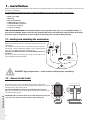
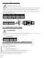
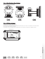
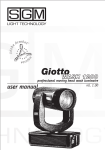
Giotto spot 1200
P r o f e s s i o n a l
User’s Manual rel. 1.00
M o v i n g
h e a d
General instructions
Read the instructions in this handbook carefully, as they give important information regarding safety during installation, use and
maintenance.
Be sure to keep this instruction manual with the fixture, in order to consult it in the future. If the fixture is sold or given
to another operator, make certain he or she also receives the manual, to be able to read about its operation and follow
the relative instructions.
* This fixture is not intended for home use.
* After having removed the packaging, check that the fixture is not damaged in any way. If in doubt, don't use it and contact an
authorized SGM Technical Service Centre.
* Packaging material (plastic bags, polystyrene foam, nails, etc.) must not be left within children's reach, as it can be dangerous.
* This fixture must only be operated by adults. Do not allow children to tamper or play with it.
* Electrical work necessary for installing the fixture must be carried out by a qualified electrician or experienced person.
Never use the fixture under the following conditions:
* In places subject to excessive humidity
* In places subject to vibrations or bumps.
* In places with a temperature of over 45°C or less than 2°C
* Protect the fixture from excessive dryness or humidity (ideal conditions are between 35% and 80%).
* Do not dismantle or modify the fixture.* Make certain that no inflammable liquids, water or metal objects enter the fixture.
* Should any liquid be spilled on the fixture, disconnected the power supply to the fixture immediately. * In the event of serious
operating problems, stop using the fixture immediately and either contact the nearest SGM sales point for a check or contact
the manufacturer directly.
* Do not open the fixture - there are no user serviceable parts inside.
* Never try to repair the fixture yourself. Repairs by unqualified people could cause damage or faulty operation. Contact your
nearest authorized service centre.
• When carrying out any work, always comply scrupulously with all the norms (particularly regarding safety) currently
in force in the country in which the fixture's being used.
Always insist on original spare parts being fitted.
General warranty conditions
• The unit is guaranteed for 12 months from the date of purchase against manufacturing material defects.
Breakdown caused by carelessness and improper use of the fixture is excluded.
• The guarantee is no longer valid if the unit has been tampered with or repaired by unauthorized personnel.
Replacement of the fixture is not foreseen by the guarantee.
• External parts, knobs, switches, removable parts and lamps are excluded from the guarantee: these are covered by their
manufacturers' guarantee conditions.
• Transport costs and related risks are borne by the fixture's owner.
The guarantee is valid to all effects only on presentation of the guarantee certificate to the manufacturer or the nearest SGM
technical assistance centre.
Giotto spot rel.1.00
• Always quote the unit's serial number and model when contacting your reseller for information or assistance.
Protect the environment: don't throw packing material into your garbage can
- return it to your SGM retailer or take it to the nearest
special waste collection point.
2
index
Intruduction
Main features
Technical Specifications
1.0 - Installation
1.1 - Locking and unlocking the mechanism
1.2 - Access to the interior
1.3
- Fitting the lamp
1.4 - Lamp alignment
1.5 - Power cable construction
1.6 - Giotto Spot's power supply
1.7 - Installing the fixture on a support structure
1.8 - Positioning the fixture
1.9 - Installing clamps
2.0 - Signal cable construction
2.1 - Construction of the DMX terminator
2.2 - RS-232 connection
3 - Microcomputer control
3.1 - Navigating in the menu
3.2 - Allocating the start channel
3.3 - Pan direction
3.31 - Limiting Pan
3.4 - Tilt direction
3.41 - Limiting tilt
3.5 - Inverting Pan/Tilt
3.6 - Lamp elapsed time meter
3.61 - Resetting the lamp's elapsed time meter
3.7 - Lamp strike counter
3.71 - Resetting the lamp's strike counter
3.8 - Fixture operating time meter
3.9 - Input signal
3.10 - Pan/Tilt resolution
3.11 - Remote control of lamp ignition
3.12 - Remote fixture reset
3.13 - Display brightness
3.14 - Display reading position
3.15 - Test functions
3.16 - Control of the acceleration of movement speed
3.17 - DMX DLY
3.18 - SLLF
3.19 - Reserved functions
4 - Giotto Spot 1200 control channels
5- Iris channel -ch5 6 - Color channel - CH67 - Gobo channel - CH7 8 - Shutter/Strobe channel - CH8 9 - Dimmer - ch 9 -24
10 - Gobo rotation - ch 1011 - Prisms - ch 11 12 - Prism Rotation - ch 12 13 - Electronic focus - ch 13 14 - Additional lenses - ch 14 15 - Color Filters - ch 15 16 - Frost - ch 16 17 - Mspeed - ch 17 18 - Lamp ignition and remote reset- ch 18 -
Giotto spot rel.1.00
4
5
7
8
8
8
9
9
10
10
10
11
11
12
12
13
14
14
16
17
17
17
17
18
18
18
18
18
19
19
19
19
19
20
20
20
20
20
21
21
22
22
23
24
25
25
26
25
26
27
27
27
28
28
28
EN
I
D
F
E
Appendix
3
Introduction
Giotto spot rel.1.00
Giotto Spot 1200 is an innovative professional SGM moving head fixture designed and built for use in large show events, theatres, TV studios and entertainment venues in general.
The result of SGM's many years' experience in mechanical and electronic design, thanks to its avant-garde performance, Giotto
Spot 1200 is one of the world's top fixtures.
The use of an MSR 1200SA discharge lamp and a perfect optical system in fact make it one of the best fixtures on the market
today as far as power and luminosity are concerned.
The lamp and electronics are powered by an electronic ballast entirely designed by the SGM Research & Development Centre
which ensures flicker-free light, bright steady light beams and lower weight than fixtures with traditional ballasts. Movement precision and speed are guaranteed by stepper motors, controlled by no less than 5 microprocessors. An ingenious system allows
the fixture to be automatically repositioned in the event of accidental head movement.
Thanks to its truly innovative technical features, Giotto Spot 1200 is a fixture able to offer Lighting Designers excellent solutions
to all their needs.
Made in Italy by SGM Electronic
Stampato in Gennaio 2000 Rel.1.00
4
Main features
Lamp
Giotto Spots use a Philips MSR 1200SA 6500°K discharge lamp, without doubt the ideal light source for this type of fixture, as it
combines reliability and long life (approximately 500 ) with astonishing luminous power.
Effects
- Iris
- Linear 0÷100% dimmer
- Shutter/Strobe from 1-10 fps - can run in music sync
- Electronic focus
- 72 colors + effects wheel
- Colorchanger with music sync and/or blackout
- 4 rotary indexed gobos + 4 fixed (all interchangeable)
- 24 gobo combinations obtainable by superimposing the two wheels
- Gobo change with music sync and/or blackout
- 2 rotary prisms with adjustable speed in both directions
- 1 variable filter frost
- 1 frost filter with adjustable beam
- 1 3,200°K color conversion filter (full CTO)
- 1 half CTO conversion filter
Movement
- 540° Pan (3.8 sec.) and 270° Tilt (2.4 sec.)
- 8/16 bit movement resolution
- Automatic repositioning in the event of accidental head movement
- invertible Pan/Tilt movement
- Adjustable Pan/Tilt offset
- Adjustable acceleration and speed parameters
Electronic Ballast
Supplied as standard with every fixture
- Automatic universal 90/245V 50/60Hz power supply
- Flicker-free
- Reduction of lamp power in the event of fixture overheating
- Power Factor Correction
- Automatic energy saving if the beam is blacked out
- Automatic lamp re-strike
Optics
- High luminous efficiency optics
- 4 beam angles - 9°, 12°, 15° and 18°
Display/Microcomputer
- Personalization of the fixture according to installations: test functions for all effects; enabling of remote lamp On/Off via DMX;
enabling of fixture reset via DMX; fixture addressing; display “flip” function (rotation through 180°); dimmable display, and more:
Display of data such as: lamp elapsed time and number of strikes, fixture operating time, software version supported.
Control signal
Giotto spot rel.1.00
Input signal DMX 512 – RS 232
Clamping system
- “Fast-Lock” clamp supplied as standard
- Several mounting points for clamps, enabling the fixture to be mounted on any type of truss
- Connection point for safety cable
EN
I
D
F
E
Appendix
5
Accessories
Giotto spot rel.1.00
- Light Dome for outdoor protection cod: 0202406
- Single flight case cod: 0061741
- Double flight case cod: 0061744
- Optional clamp unit cod: 0202403
6
Technical specifications
LAMP:
MSR 1200SA GY16 COLOR TEMPERATURE: 6500K
LIGHT OUTPUT: 96000 LUMEN
LIFE: 500 HOURS
POWER SUPPLY:
ELECTRONICS AND LAMP ARE POWERED BY A SWITCHING POWER SUPPLY. THE FIXTURE CAN OPERATE AT ANY VOLTAGE
90V AND 240V 50HZ, 60HZ.
BETWEEN
POWER ABSORBED:
1500W
OPTICAL SYSTEM: I
NTERNAL OPTICAL GROUP COMPRISING HIGH LUMINOUS EFFICIENCY POLISHED REFLECTOR AND DOUBLE CONDENSER;
BEAM ANGLES:
4
9° - 12° - 15° - 18°; ELECTRONIC FOCUS.
ELECTRONICS:
CS0276 (INPUT
SIGNAL);
MOTOR DRIVER CONTROL)
CS0244 + CS0245 (ELECTRONIC BALLAST); CS 0252 (IGNITOR); CS 0268 (ELECTRONICS
CS0273(PAN/TILT MOTOR DRIVER CONTROL)
AND-
SETTING:
VIA BUILT-IN MICROCOMPUTER
CONTROL SIGNAL:
USITT DMX 512 OR RS-232
DMX CONTROL CHANNELS:
18 CH
AUTOMATIC REPOSITIONING:
VIA OPTICAL SENSORS CONSTANTLY CONTROLLING
PAN AND TILT POSITION AND CORRECTING IT IN THE EVENT OF THE MOVING
HEAD BEING ACCIDENTALLY MOVED.
COOLING:
FORCED VENTILATION BY MEANS OF TWO LOW-NOISE FANS WHOSE SPEED IS ELECTRONICALLY CONTROLLED ACCORDING TO
CHANGES IN TEMPERATURE IN THE FIXTURE.
PROTECTION FUSES:
2X16A CF 6.3 X 32 TYPE FUSES
BODY:
SHEET METAL WITH POWDER PAINT FINISH AND EXTRUDED/DIE-CAST ALUMINIUM WITH POWDER PAINT FINISH.
DIMENSIONS:
(HXLXD) 77X53X47.5
WEIGHT:
Giotto spot rel.1.00
Kg 30
SGM Elettronica reserves the right to improve or modify their products
at any time without prior notice.
Always consult the handbook of the unit being used to avoid errors and differences between t
he actual functions and those shown in the book.
EN
I
D
F
E
Appendix
7
1- installation
Before proceeding with fixture installation, make certain that the packing contains all the items shown in the following list and ensure that
the fixture is undamaged.
If in doubt, don't use the fixture and contact an authorized SGM technical assistance centre and the freight company.
In fact, only the recipient can claim for any damage caused to the fixture during transport.
• Giotto spot 1200
• Warranty
• Instruction Manual
• 1 Male XLR 5 P connector
• 1 Female XLR 5 P connector
• 1 Power-con connector
• 2 Fast-Lock clamps
KEEP THE PACKING MATERIAL. Packing material (plastic bags, polystyrene foam, nails, etc.) is potentially hazardous, so
must never be left within children's reach. Use the original packing in the event of having to return the fixture to the manufacturer for repair or maintenance: it's been designed specifically to protect the fixture during transport.
ck
ck
un
lo
remove lock
before turning
on the
fixture
togliere il
blocco prima
di accendere
il proiettore
un
lo
remove lock
before turning
on the
fixture
togliere il
blocco prima
di accendere
il proiettore
lo
ck
ck
lo
ck
lo
Giotto fixtures are fitted with a mechanical locking system for the
moving parts.
The moving head and yoke must be locked every time the fixture is
transported, using the appropriate flightcase or the original packing,
which have an suitable shock-proof support system.
Remember to ALWAYS unlock the mechanism BEFORE switching on
the fixture!!!
The fixture is locked and unlocked by turning the two knobs on the
yoke, following the printed indications
ck
1.1- Locking and unlocking the mechanism
un
lo
lo
ck
ck
remove lock before turning on the fixture
togliere il blocco prima di accendere il proiettore
un
lo
remove lock before turning on the fixture
togliere il blocco prima di accendere il proiettore
DANGER! high temperature - avoid contact with persons and things.
1.2 - Access to the inside
Giotto spot rel.1.00
Giotto fixtures have a simple mechanism for opening the moving head.
To open the two covers, just turn the two locking screws shown in the illustration through 180°, then raise the cover.
Any work must ALWAYS by carried out by qualified technical personnel.
When work is finished, close the covers again, making certain that they are closed against the fixture body.
ATTENTION: make sure that the fixture is off and the temperature of the parts
can't cause burns (wait for at least 30 minutes after switching off).
8
1.3 - Lamp installation
ATTENTION! This fixture is designed exclusively for use with Philips MSR 1200SA lamps. NEVER
USE ANY OTHER TYPES OF LAMPS.
• Disconnect the power supply before carrying out any work on the fixture.
• Make certain that the fixture is off and the temperature of the components can't cause burns (wait at least 20
minutes after switching off).
• Never carry out any work if the fixture doesn't have its protective covers or its lenses are damaged. Discharge
lamps can explode.
• Never look directly at the lamp when it's lit - discharge lamps emit UV rays which are dangerous for sight.
There's an optical group in the fixture's moving head. Follow these instructions when fitting or replacing the lamp.
1. Disconnect the power supply and wear protective gloves and glasses.
2. Remove the head's top cover
3. (fig.1) Unscrew the two locking screws (A) on the aluminium support which fix the lampholder base to the optical group
4. (fig.2) Raise the aluminium support and fit the lamp in the base. Avoid touching the lamp bulb with your fingers. Should this
happen, clean it before use with a soft cloth and alcohol, then clean with a dry cloth.
5. (fig.3) Tighten the screws again, making certain that the lamp wires are positioned in the appropriate slots.
6. Close the cover again.
A
MSR 1200SA
A
fig.1
fig.2
fig.3
1.4 - Lamp Alignment
After each relamping, it's important to align the lamp with the optical group in order to obtain maximum uniformity and light output.
1. Fit the new lamp, close the fixture and switch it on.
2. Connect the fixture to a lighting console.
3. Point the fixture at a flat surface (if possible light coloured) at a distance of at least 3metres.
4. Set the control channels in such as way as to obtain the projection of a white beam. Then: IRIS open, DIMMER at maximum luminosity,
suitable FOCUS, no GOBO or COLOR projected.
5. (Fig.4) Loosen the two fastening screws (A) and use the knobs on the sides to align the lamp horizontally.
6. (Fig.5) Use the large centre brass ferrule to align the lamp vertically with respect to the optical group.
7. The lamp is aligned correctly when a uniform beam is obtained, without any shadows or zones which are brighter than others.
8. (Fig.6) Tighten the fastening screws and close the cover again
A
EN
fig.4
I
D
fig.5
F
E
Appendix
A
Giotto spot rel.1.00
A
A
fig.6
9
1.5-Power cable construction
DANGER! ELECTRICAL SHOCK HAZARD
• Electrical work necessary for installing the fixture must be carried out by a qualified electrician or an experienced
person.
• The fixture must be suitably earthed. Failure to comply with this automatically invalidates the guarantee.
The POWER-CON type connector supplied along with the Giotto is indispensable for connecting the fixture to the power
supply. The following design shows how to connect the connector to the cable, whereas the table shows the symbols
normally used to indicate connections.
When in doubt, consult a qualified electrician.
CABLES
Brown
Blue
Yellow/Green
PIN
Phase
Neutral
Ground
TYPICAL
“L”
“N”
US
Yellow/Copper
Silver
Green
UK
Red
Black
Green
N
Conductors' cross-section
Power supply
Minimum cross-section
230 V
3x1,5
120 V
3x2,5
L
1.6 - Giotto Spot's power supply
ATTENTION!!
• Don't power the Giotto with a dimmer circuit - this could damage the electronic ballast.
• Before connecting the fixture, make certain that the data on the fixture's plate correspond with those of the local main power
supply.
• The fixture must be connected to a cut-off circuit with the following characteristics:
Cut-off circuit
Power supply
230 V
120 V
in
16A
32A
id
0,03A
0,03A
Giotto spot rel.1.00
1.7- Installing the fixture on a support structure
Read the following safety information before proceeding with the installation of the fixture:
• Fixture not for domestic use.
• Do not install the fixture near sources of heat.
• Install the fixture in a well ventilated place.
• Avoid blocking air intakes and outputs.
• Do not use the fixture:
- In places subject to vibrations or bumps
- In places with excessive humidity
- In places subject to temperatures of more than 45° or less than 2°C
• Protect the fixture from excessive humidity (ideal values are between 35 and l’80%).
• Avoid inflammable liquids, water or metallic objects entering the fixture .
• Keep any inflammable material at a distance of at least 1.5m from the fixture.
• Position the fixture at least 1.5m. from the surface to be lit.
• Don't lift the fixture holding it by the moving part (the head).
10
1.8 - Positioning the fixture
Can be installed in any position.
down
enter
down
enter
up
gain
up
mic
GIOTTO REL. 1.00
control
in/out dmx
moving head wash luminaire
Giotto1200
fuses
main power
main power
fuses
Giotto1200
moving head wash luminaire
in/out dmx
control
GIOTTO REL. 1.00
mic
down
up
up
down
enter
gain
enter
OK
OK
OK
1.9 - Fitting clamps
Always use two clamps to hang the fixture.
Fix the fixture to the support structure using safety chains fitted to the 2 holes on the underside of the fixture's base.
Don't fix the safety chain to the handles.
Remember to unlock the PAN and TILT locking system once the fixture is mounted on the support structure.
safety chain socket
15°
Giotto spot rel.1.00
•
•
•
•
EN
I
D
F
E
Appendix
11
2.0-Construction of the signal cable
Giotto 1200 has a DMX 512 input fitted with standard 5-pin XLR connectors. Screened cables in compliance with EIA RS485 specifications and the following characteristics must be used for connections:
- 2 conductors plus screen
- 120Ohm impedance
- low capacitance
- max. transmission rate 250kBaud.
Cable connections:
1
5
4
3
COMMON
DMXDMX+
2
see illustration, taking care with the screen, which must be connected
to Pin 1
ATTENTION: the screened parts of the cable (sleeve) must NEVER be connected to the system's
earth, as this would cause faulty fixture and controller operation.
Example of connection of the DMX line
main power
main power
fuses
fuses
Giotto1200
Giotto1200
moving head wash luminaire
moving head wash luminaire
in/out dmx
in/out dmx
control
in/out dmx
control
GIOTTO REL. 1.00
control
GIOTTO REL. 1.00
GIOTTO REL. 1.00
mic
down
mic
up
up
down
enter
gain
enter
gain
enter
up
down
down
enter
up
down
up
up
mic
down
enter
main power
fuses
Giotto1200
moving head wash luminaire
gain
enter
DMX linea
DMX controller
Pilot2000
DIMMR COLOR GOBOS SHUTT ROTGB FROST 0
0
0
0
0
0
-
Termination DMX
(last ap)
0
0
universal dmx controller
on/off
operations
setup
utility
copy
enter
play
extra
lamp
reset
edit
levels
times
preset
unit
step
100%
90
80
smpte
rec
70
60
programming keyboard
50
page
40
store
1 - 20
30
21 - 40
20
10
0
memory obj
grand master
memory program
chase
psycho
pan
tilt
multifunction keyboard
1 or 21
2 or 22
3 or 23
4 or 24
5 or 25
6 or 26
7 or 27
8 or 28
9 or 29
10 or 30 11 or 31 12 or 32 13 or 33 14 or 34 15 or 35 16 or 36 17 or 37 18 or 38 19 or 39 20 or 40
To avoid the risk of faulty operation, follow these indications:
Maximum cable length: 500 metres
Max. N° of fixtures connected: 32
Cable runs: Avoid running cables alongside power supply lines.
Termination: A 120Ohm resistor between Pins 2 and 3 on the last fixture.
Giotto spot rel.1.00
2.1- Construction of the DMX termination
The termination avoids the risk of DMX 512 signals being reflected back along the cable when they reaches the end of
the line: under certain conditions and with certain cable lengths, this could cause them to cancel the original signals.
The termination is prepared by soldering a 120Ohm 1/4 W resistor between pins 2 and 3 of the 5-pin male XLR connector
(see diagram).
1
5
4
12
3
2
120Ω
2.2-RS232 connection
Giotto spot rel.1.00
For this connection, use good quality screened coax cable (RG58 50Ohms) to avoid problems with signal transmission and
faulty fixture operation.
Connectors must always be 5-pin XLRs. Refer to the diagram for wiring.
EN
I
D
F
E
Appendix
13
3.0 - “Control” microcomputer
Giotto Spot 1200 is equipped with a microcomputer which allows to customize the fixture to suite the type of installation.
In fact, it's possible to assign the start address; obtain information regarding lamp life and fixture operation time; run test
programs to check correct fixture operation and customize some parameters.
3.1- Navigating in the menu
E010485 - 31.
When it's switched on, the fixture runs a start-up reset procedure and the display indicates if there's an input signal or not.
Giotto 1.4
The 3 keys under the display are for selecting and using the various submenus which make up the main menu.
1
E010485 - 31
E010485 - 31
- UP/DOWN keys: used to scroll the various items in the menu. In the selected menu, used to change the required parameters.
- ENTER key: used to access to the selected menu and, once the necessary changes have been made, is used to confirm
them.
2
Giotto 1.4
Giotto spot rel.1.00
Accel
14
Menu
Description
Options
(Default configurations are shown in bold text)
Addr=xxx
Range 001-487
Addressing the fixture
Pmove
NORM
Normal control of Pan from left to right
REV
Control of Pan inverted - from right to left.
PP_min
Range 000-540
Sets Pan starting angle.
Default Configuration = 000 degrees
PP_max
Range 000-540
Range 000-540 Sets Pan ending angle.
Default Configuration = 000 degrees
NORM
Normal control of Tilt from up to down.
REV
Control of Tilt inverted, from bottom to top.
TP_min
Range 000-270
Range 000-270 Set Tilt starting angle.
Default Configuration = 000 degrees
TP_max
Range 000-270
Range 000-270 Sets Tilt ending angle
Default Configuration = 000 degrees
ON
Pan is controlled by Tilt commands and vice versa
OFF
Normal control of Pan and Tilt
.
.
Tmove
Swap
Lmp_H
Read-only menu. Records the elapsed time of the lamp.
Can be reset.
Lmp_st
Read-only menu. Records the number of lamp strikes.
Can be reset.
SCN_h
Read-only menu. Records total fixture operating time.
SIGN
DMX
Signal DMX selected
RS-232
Signal RS-232 selected
16 bit
8 bit
Allows to select movement resolution.
Default configuration = 16-bit
EN
Remote control of lamp ignition enabled.
DS
Remote control of lamp ignition disabled.
EN
Remote control of reset enabled.
DS
Remote control of reset disabled.
Speed
100% - 92%
84% - 76%
Possibility of slowing the maximum speed of PAN and TILT movement.
Default configuration = 100%
Accel
Fast
Optimizes speed performance.
Slow
Optimizes performance for the smooth movement
100-53-40-27-20-136-0 (%)
Allows to regulate the brightness of the display.
Default configuration=40%
SMD
LMP_ctr
RST_ctr
Inverts the reading position of the display.
Used according to the position of the fixture.
DsplFlip
DMXdly
Range 8-998 sec
It's possible to decide for how many seconds the fixture's last operating
status must be held when there's no DMX signal (default =20sec.).
it maintains always the last condition of job independently from how
much time lacks the dmx
UNL
ON
Energy saving enabled
OFF
Energy saving disabled
Giotto spot rel.1.00
Bright
SLLF
TEST
Reserved
Read-only menu giving information on the software version
supported by the fixture.
Giotto 1.4
EN
I
D
F
E
Appendix
15
3.2 - Allocating the first addressed channel
In order to receive the commands necessary to operate from a lighting console, each fixture has to be allocated a start
address. This address normally indicates the first channel used (start channel) and can be allocated following a different
criterion from that used to connect the signal line. Giotto Spot uses 18 controls channels, so during allocation, this quantity
must be borne in mind to avoid possible overlapping of other fixtures' channels, which would cause problems with the
perfect control of all the available functions. Should it be necessary, it's possible to allocate the same start channel to
several fixtures, in this case the fixtures will all follow the same commands, but can't be controlled separately.
To address fixtures correctly, proceed as follows:
1. Connect Giotto Spot to the power supply, wait until it has completed reset operations and “DMX signal” appears on
the display.
2. Use the UP/DOWN keys to find the “Addr” menu
3. Press ENTER to confirm. The message on the display starts to flash.
4. Use the UP/DOWN keys to select the channel required.
5. Press ENTER to confirm.
Fixture
N.
Giotto spot rel.1.00
1
2
3
4
5
6
7
16
Start
Address
001
019
037
055
073
091
109
Fixture
N.
8
9
10
11
12
13
14
Start
Address
127
145
163
181
199
217
235
Fixture
N.
Start
Address
Fixture
N.
Start
Address
15
16
17
18
19
20
21
253
271
289
307
325
343
361
22
23
24
25
26
27
28
379
397
415
433
451
469
487
3.3 - Direction of Pan movement
This function allows to decide the direction in which the Giotto's moving head pans, indispensable when several
fixtures are installed in order that fixtures installed opposite each other move in the same direction when they
receive a command.
To modify Pan movement, proceed as follows:
1.
2.
3.
4.
5.
Connect the Giotto Spot to the power supply, wait till it has completed reset operations and “DMX signal”
appears on the display.
Use the UP/DOWN keys to find the “Pmove” menu
Press ENTER to confirm. The message on the display will start to flash.
Use the UP/DOWN keys to select which of the two available options is required (see table pag.15).
Press ENTER to confirm.
3.31 - Setting Pan starting angle
The Giotto fixture has a Pan movement range of 540° (a revolution and a half ). If the entire excursion doesn't
have to be used, two parameters allow to set the starting angle (PP_min) and ending angle (PP_max). The only
limit is the minimum difference between starting (MIN) and ending angle (MAX), which is 4°.
To limit Pan movement, proceed as follows:
1.
2.
3.
4.
5.
Connect Giotto Spot to the power supply, wait till it has completed reset operations and “DMX signal”
appears on the display.
Use the UP/DOWN keys to find the “PP_min” menu if the starting angle has to be modified. If the ending
angle has to be modified, find the “PP_max” menu.
Press ENTER to confirm. The message on the display will start to flash.
Use the UP/DOWN keys to select the new starting (or ending) angle.
Press ENTER to confirm.
3.4 - Direction of Tilt movement
This function allows to decide the direction in which the Giotto's moving head tilts, indispensable when several
fixtures are installed in order that fixtures installed opposite each other move in the same direction when they
receive a command.
To modify Tilt movement, proceed as follows
1. Connect Giotto Spot to the power supply, wait till it has completed reset operations and “DMX signal”
appears on the display.
2. Use the UP/DOWN keys to find the “Tmove” menu
3. Press ENTER to confirm. The message on the display will start to flash.
4. Use the UP/DOWN keys to select which of the two available options is required (see table pag.15).5. Press
ENTER to confirm.
3.41-Limiting Tilt movement
The Giotto fixture has a Tilt movement range of 270° (3/4 of a revolution). If the entire excursion doesn't have to
be used, two parameters allow to limit the starting angle (TP_min) and ending angle (TP_max). The only limit is
the minimum difference between starting (MIN) and ending (MAX), which is 4°.
To limit the Tilt movement, proceed as follows:
2.
3.
4.
5.
EN
Connect Giotto Spot to the power supply, wait till it has completed reset operations and “DMX signal”
appears on the display.
Use the UP/DOWN keys to find the “TP_min” menu if the starting angle is to be modified. If the ending
angle is to be changed, find the “TP_max” menu.
Press ENTER to confirm. The message on the display will start to flash.
Use the UP/DOWN keys to select the new starting (or ending) angle.
Press ENTER to confirm.
I
D
F
E
Appendix
Giotto spot rel.1.00
1.
17
3.5 - Pan/Tilt inversion
This function also allows to optimize the movement of the Giotto's moving head in relation to the operator's
position, in order to simplify all positioning procedure.
When SWAP is enabled (ON), this means that the lighting console sends the data regarding Pan to the Tilt controls and vice versa.
To invert PAN and TILT movement, proceed as follows:
1.
2.
3.
4.
5.
Connect Giotto Spot to the power supply, wait till it has completed reset operations and “DMX signal”
appears on the display.
Use the UP/DOWN keys to find the “SWAP” menu.
Press ENTER to confirm. The message on the display will start to flash.
Use the UP/DOWN keys to select which of the two available options is required (see table pag.15)
Press ENTER to confirm.
3.6 - Lamp elapsed time meter
The Giotto microcomputer stores various data, including that relative to the number of hours the lamp is lit (elapsed time). This is necessary to know in advance when it's almost time for relamping: lamp life is approximately
750 hours.
To see how many hours a lamp has been used, proceed as follows:
1.
2.
Connect Giotto Spot to the power supply, wait till it has completed reset operations and “DMX signal”
appears on the display.
Use the UP/DOWN keys to find the ““Lmp_H” menu. The total number of hours the lamp has been lit will be
displayed automatically.
3.61 - Resetting the lamp elapsed time meterAd
Each time a new lamp is fitted, it's possible to reset the meter indicating the elapsed time in order to have the
real elapsed time for the lamp about to be fitted.
To reset the elapsed time meter, proceed as follows:
1.
2.
3.
4.
5.
6.
Connect Giotto Spot to the power supply, wait till it has completed reset operations and “DMX signal”
appears on the display.
Use the UP/DOWN keys to find the ““Lmp_H” menu.
Press ENTER to confirm. The message on the display will start to flash.
The DOWN key can be used to reset the meter.
On the contrary, pressing the UP key restores the previous value.
Press ENTER to confirm the changes.
3.7 - Lamp strike meter
The Giotto's microcomputer stores various data, including those relative to the number of lamp strikes. This
information is important because needless lamp strikes causes stress to materials and components, so can contribute to reducing lamp life.
To know how many times a lamp has been ignited:
1.
2.
Connect Giotto Spot to the power supply, wait till it has completed reset operations and “DMX signal”
appears on the display.
Use the UP/DOWN keys to find the ““Lmp_st” menu. The number of lamp strikes will be displayed automatically.
3.71- Resetting the lamp strike meter
Giotto spot rel.1.00
Each time the fixture is relamped, it's possible to reset the meter which counts the strikes, in order to have number of actual strikes for the lamp about to be installed.
To reset the meter, proceed as follows:
1.
2.
3.
4.
5.
6.
18
Connect Giotto Spot to the power supply, wait till it has completed reset operations and “DMX signal”
appears on the display.
Use the UP/DOWN keys to find the ““Lmp_st” menu.
Press ENTER to confirm. The message on the display will start to flash.
The DOWN key can be used to reset the meter.
On the contrary, pressing the UP key restores the previous value.
Press ENTER to confirm the modifications.
3.8 - Fixture operating time meter
This function allows to see for how many hours the fixture has been operating. This meter cannot be reset.
To see for how many hours the fixture has been used, proceed as follows:
1.
2.
Connect Giotto Spot to the power supply, wait till it has completed reset operations and “DMX signal”
appears on the display.
Use the UP/DOWN keys to find the “Scn_H” menu. The number of fixture operating hours will be displayed
automatically.
3.9 - Input signal
This function allows to choose the type of input signal to be used: DMX 512 or RS-232.
To select the required signal, proceed as follows:
1.
2.
3.
4.
5.
Connect Giotto Spot to the power supply, wait till it has completed reset operations and “DMX signal”
appears on the display.
Use the UP/DOWN keys to find the “Sign=DMX” menu.
Press ENTER to confirm. The message on the display will start to flash.
Use the UP/DOWN keys to select the type of signal to be used.
Press ENTER to confirm the changes.
3.10 - Pan/ Tilt movement resolution
This function allows to define the movement resolution (16 or 8 bit). The difference is in the number of steps in
which the range of head movement is divided.
In 16-bit mode, 540° of Pan and 270° of Tilt are divided into 65,536 steps, ensuring very smooth precision even at
very low speeds. In 8-bit mode, the number of steps is 256, which nevertheless allow precise movements.
1.
2.
3.
4.
5.
Connect Giotto Spot to the power supply, wait till it has completed reset operations and “DMX signal”
appears on the display.
Use the UP/DOWN keys to find the ““SMD” menu.
Press ENTER to confirm. The message on the display will start to flash.
Use the UP/DOWN keys to select the type of resolution required.
Press ENTER to confirm the modifications.
3.11- Remote control of lamp ignition
Operators can decide if the ignition of the Giotto's lamp is to be controlled from a lighting console or be automatic.
To access this function, proceed as follows:
1. Connect Giotto Spot to the power supply, wait till it has completed reset operations and “DMX signal”
appears on the display.
2. Use the UP/DOWN keys to find the “LMP_ctr” menu.
3. Press ENTER to confirm. The message on the display will start to flash.
4. Use the UP/DOWN keys to select the required option.
5. Press ENTER to confirm the modifications.
3.12 - Remote control of fixture reset
Using this menu, it's possible to decide whether to reset the fixture via remote control or not.
To enable this function , proceed as follows:
2.
3.
4.
5.
EN
Connect Giotto Spot to the power supply, wait till it has completed reset operations and “DMX signal”
appears on the display.
Use the UP/DOWN keys to find the “RST_ctr” menu.
Press ENTER to confirm. The message on the display will start to flash.
Use the UP/DOWN keys to select the required option.
Press ENTER to confirm the changes.
I
D
F
E
Appendix
Giotto spot rel.1.00
1.
19
3.13 - Display brightness
Operators can select one of the brightness levels available for the Giotto display, which can be standard or very
low. This option is intended for theatre and television use, where excessive brightness can be troublesome.
To change display brightness, proceed as follows:
1. Connect Giotto Spot to the power supply, wait till it has completed reset operations and “DMX signal” appears
on the display.
2. Use the UP/DOWN keys to find the “Bright” menu.
3. Press ENTER to confirm. The message on the display will start to flash.
4. Use the UP/DOWN keys to select the required option from those available.
5. Press ENTER to confirm the modifications.
3.14 - Display reading position
When the fixture is mounted "upside down" on a structure, operators can turn the display through 180°, thus
greatly facilitating the reading of the menus on the display.
To change the reading position, proceed as follows:
1. Connect Giotto Spot to the power supply, wait till it has completed reset operations and “DMX signal” appears
on the display.
2. Use the UP/DOWN keys to find the “Dspl Flip” menu
3. Press ENTER to confirm. The message on the display will start to flash.
4. Use the UP/DOWN keys to select the required option.
5. Press ENTER to confirm the modifications.
3.15 - Test functions
Test programs can be used in the event of it being necessary to check the correct operation of the fixture or some
of its parts.
To selection the required test program, proceed as follows:
1.
2.
3.
4.
5.
6.
Connect Giotto Spot to the power supply, wait till it has completed reset operations and “DMX signal”
appears on the display.
Use the UP/DOWN keys to find the “Test” menu.
Press ENTER and hold it down for a few seconds to confirm. The message on the display will start to flash.
Use the UP/DOWN keys to select the program corresponding to the part of the fixture to be tested.
Press ENTER to run the test program.
To quit the test functions, press ENTER once, then press it again for a few seconds until “Test” re-appears on
the display.
3.16-Control of the acceleration of movement speed
Movement can be optimized by changing the speed (SPEED) and acceleration (ACCEL) parameters, obtaining
smooth fast or slow movements as required.
To optimize movement, proceed as follows:
1.
2.
3.
4.
5.
Connect Giotto Spot to the power supply, wait till it has completed reset operations and “DMX signal”
appears on the display.
Use the UP/DOWN keys to find the “Speed” or “Accel” menu.
Press ENTER to confirm. The message on the display will start to flash.
Use the UP/DOWN keys to select the required option.
Press ENTER to confirm the changes.
Giotto spot rel.1.00
3.17-dmx dly
This allows to set the for how many seconds the fixture's last operating settings are maintained should there be
no DMX signal.
This function is indispensable in those cases in which there is an accidental DMX failure.
To set the required time, proceed as follows:
1.
2.
3.
4.
5.
20
Connect Giotto Spot to the power supply, wait till it has completed reset operations and “DMX signal”
appears on the display.
Use the UP/DOWN to find the “DMXDLY” menu.
Press ENTER to confirm. The message on the display will start to flash.
Use the UP/DOWN keys to select the required time.
Press ENTER to confirm changes.
3.18 - SLLF
This is an energy-saving function. If the function is enabled (SLLF=ON), the fixture reduces lamp power by dimming it electronically after the shutter has been closed for 30 seconds.
Maximum power will automatically be restored as soon as the shutter is reopened.
To enable this function, proceed as follows:
1.
2.
3.
4.
5.
Connect Giotto Spot to the power supply, wait till it has completed reset operations and “DMX signal” appears
on the display.
Use the UP/DOWN keys to find the “SLLF” menu.
Press “Enter” to confirm. The message on the display will start to flash.
Use the UP/DOWN keys to select the required option.
Press “Enter” to confirm changes.
3.19 - Reserved functions
Giotto spot rel.1.00
Some fixture functions can't be accessed by operators as they regard software sections as yet to be defined in
this firmware release. When RESERVED appears on the display, you're in this section. Access is forbidden.
EN
I
D
F
E
Appendix
21
4.0 - GIOTTO SPOT 1200 CONTROL CHANNELS
DMX
Functions
Channel
Ch1
Ch2
Description
Pan High byte in 8-bit operation
Only this byte is sent
Pan Low byte for
16-bit positioning
Tilt High byte in 8-bit
Operation Only this byte is sent
Tilt Low byte for 16-bit
positioning
Pan MSB
Pan LSB
Ch3
Tilt
MSB
Ch4
Tilt
LSB
Ch5
Iris
Ch6
Color
Ch7
Gobos
Ch8
Shutter/
Strobe
Ch9
Dimmer
2 4-position wheel for 25 combination,
gobo wheel rotation, music change
Shutter and strobe with music sync
Black –out gobo and colour change
The dimmer is partially electronic and
partially mechanical
Ch10
Rotation
Gobos
Indexed position and rotation in
both directions at adjustable speed See table See table
Ch11
Prisms
Allows to insert one of the two
rotary prisms or neither See table
Iris aperture control
Linear range 0 – 255
24 combinations of color + rainbow
Ch12
Ch13
+ music change
See table
See table
See table
Linear range 0 – 255
See table
Control of the prisms' rotation
speed in one direction or the other See table See table
Rotation
Prisms
Electronic
Focus
Allows to focus the image Linear range
Linear range 0 - 255
Ch14
Lenses
Allows to insert lenses for
obtaining 4 beam angles See table
See table
Ch15
Filters
Conversion filters + Effects See table
See table
Ch16
Frost
Variable frost filter Range 0 - 255
Range 0 - 255
Ch17
Mspeed
Movement speed
Controlled cross-fade
Slowest vel. min
Fastest vel.max
See table
Ch18
Reset/Lamp
See table
Giotto spot rel.1.00
5.0-IRIS CHANNEL - CH 5Adjustable by channel 5, it allows the linear regulation of amplitude of the luminous bundle beam.
Peculiar characteristics of the diaphragm are the high speed of opening / closing (100 mS) and low noise.
DMX512
Level range 0-- 255
0
000-255
255
22
FUNCTION
MINIMAL OPENING
LINEAR REGULATION
MAXIMUM OPENING
6.0 - COLOR CHANNEL - CH 6Giotto Spot 1200 is fitted with an exclusive color generation system comprising 12 frames containing dichroic colour filters. Color changes are controlled by Channel 6, allowing to select 24 different colors which, combined with the two
colour conversion filters, produce 72 different tones. As well as selecting the colour, it's also possible to use some functions with great visual impact, such as running the colourchanger in sync with the music or continuous rotation of all the
colours available at 3 different speeds (rainbow effect). By using the colour channel in combination with the strobe channel, an "autoshade" effect can be obtained, which blacks out projection for a moment when colours are changed.
CENTRAL VALUE
FUNCTION
0-7
8 - 14
15 - 21
22 - 28
29 - 35
36 - 42
42 - 49
50 - 56
57 - 63
64 - 70
71 - 77
78 - 84
85 - 91
92 - 98
99 - 105
106 - 112
113 - 119
120 - 126
127 - 133
134 - 140
141 - 147
148 - 154
155 - 161
162 - 168
169 - 175
176 - 182
186 - 189
190 - 196
197 - 203
204 - 210
211 - 217
218 - 224
3
11
18
25
32
39
46
53
60
67
74
81
88
95
102
109
116
123
130
137
144
151
158
165
172
179
186
193
200
207
214
221
WHITE
PINK
MAGENTA
LAVENDER
BLU LIGHT
AZURE
CYAN
YELLOW
AMBER
FLAME RED
WOOD
PRIMARY RED
LIGHT GREEN
GREEN AZURE
GREEN AMBER
YELLOW GREEN
GREEN CYAN
GREEN YELLOW
DARK RED
LIGHT MEDIUM BLUE
GREEN
MEDIUM BLUE
MEDIUM RED
ORANGE
DARK PURPLE
RAINBOW SPEED 1 SLOW
RAINBOW SPEED 2
RAINBOW SPEED 3
RAINBOW SPEED 4 FAST
MUSIC CHANGE AT EACH BASS BEAT
MUSIC CHANGE EVERY TWO 2 BASS BEATS
MUSIC CHANGE EVERY 3 BASS BEATS
225 - 255
236
MUSIC CHANGE EVERY 4 BASS BEATS
Giotto spot rel.1.00
DMX VALUE
EN
I
D
F
E
Appendix
23
7.0- GOBO CHANNEL - CH 7
Gobo selection is controlled by Channel 7. The gobo group comprises two independent wheels, each with four images
and a blank position.
The gobos are interchangeable and superimposing the two wheels enables 25 different combinations to be obtained.
Changeover from one gobo to another can be done rapidly and directly, or blacked out: this function is controlled by channel 8 (shutter/strobe) using the strobe/shutter's “Autoshade on Gobo” function. It's also possible to synchronize gobo
changes with a musical bass beat, in which case, gobo selection is random and in any case not synchronized on the
various fixtures.
The gobos on the rotary wheel can rotate both clockwise and counterclockwise and the position can be stored if required.
DMX
VALUE
Giotto spot rel.1.00
0 -- 8
9 -- 17
18 -- 26
27 -- 35
36 -- 44
45 -- 53
54 -- 62
63 -- 71
72 -- 80
81 -- 89
90 -- 98
99 -- 107
108 -- 116
117 -- 125
126 -- 134
135 -- 143
144 -- 152
153 -- 161
162 -- 170
171 -- 179
180 -- 188
189 -- 197
198 -- 206
207 -- 215
216 -- 225
226 -- 232
233 -- 240
241 -- 248
249 -- 255
24
CENTRAL VALUE
FUNCTION
4
13
22
31
40
49
58
67
76
85
94
103
112
121
130
139
148
157
166
175
184
193
202
211
220
230
237
245
253
WHITE - A
WHITE - B
WHITE- A
WHITE 1B
WHITE - A
GOBO 2B
WHITE - A
GOBO 3B
WHITE - A
GOBO 4B
GOBO - 4B
WHITE - B
GOBO - 3B
WHITE - B
GOBO - 2B
WHITE - B
GOBO - 1B
WHITE - B
GOBO - 1A
GOBO - 1B
GOBO - 2A
GOBO - 1B
GOBO - 3A
GOBO - 1B
GOBO - 4A
GOBO - 1B
GOBO - 4A
GOBO - 2B
GOBO - 3A
GOBO - 2B
GOBO - 2A
GOBO - 2B
GOBO - 1A
GOBO - 2B
GOBO - 1A
GOBO - 3B
GOBO - 2A
GOBO - 3B
GOBO - 3A
GOBO - 3B
GOBO - 4A
GOBO - 3B
GOBO - 4A
GOBO - 4B
GOBO - 3A
GOBO - 4B
GOBO - 2A
GOBO - 4B
GOBO - 1A
GOBO - 4B
RAINBOW A SPEED 1
RAINBOW A SPEED 2
RAINBOW A SPEED 3
MUSIC CHANGE GOBOS
8.0-CHANNEL SHUTTER/ STROBE CH - 8
The Shutter/Strobe is controlled by Channel 8. The mechanism which enables the strobe effect to be generated is the
same as that used for dimming the light beam, however it's also possible to control the light's intensity while the strobe's
enabled. This ensures instant beam blackout without any light spill.
High-impact visual effects, such as the strobe effect running in sync with the bass beat and the light blackout during color
and gobo changes can be enabled directly with this channel.
DMX VALUE
CENTRAL VALUE
0 -- 7
8 --15
16 -- 23
24 – 31
32 – 39
40 -- 47
48 -- 55
56 -- 63
64 -- 71
72 --79
80 --87
88 -- 95
96 -- 103
104 -- 111
112 -- 119
4
12
20
28
36
44
52
60
68
76
84
92
100
108
116
120 -- 136
128
137 -- 153
154 – 170
171 -- 187
188 -- 204
205 -- 221
222 -- 255
145
162
179
196
213
FUNCTION
Closed
Strobe at a frequency of 1Hz
Strobe at a frequency of 1,38 Hz
Strobe at a frequency of 1,6 Hz
Strobe at a frequency of 1,9 Hz
Strobe at a frequency of 2,3 Hz
Strobe at a frequency of 2,7 Hz
Strobe at a frequency of 3,4 Hz
Strobe at a frequency of 4 Hz
Strobe at a frequency of di 5 Hz
Strobe at a frequency of 6 Hz
Strobe at a frequency of di 7 Hz
Strobe at a frequency of 8 Hz
Strobe at a frequency of 9 Hz
Strobe at a frequency of 10 Hz
Shutter strobe low strobe effect at maximum flash
rate in sync with the bass beat
Music flash low
Open autoshade on the gobo
Open autoshade on the colors
Open autoshade on the gobo and on the colors
Open with slow gobo change
Open
9.0-Dimmer –ch 9Controlled by Channel 9 - enables linear control of light output.
Giotto's dimmer is partially mechanical and partially electronic and allows to obtain good linear regulation as well as high
operating speed and very low noise.
FUNCTION
CLOSED
LINEAR REGULATION
OPEN
Giotto spot rel.1.00
DMX512
Level range 0-- 255
0
000-255
255
EN
I
D
F
E
Appendix
25
10- GOBO ROTATION - CH 10
This channel is used to control the speed or positioning of the rotary gobos. Rotation can be in either direction at a speed
which can be regulated from a minimum of 1.5rpm to a maximum of 40rpm, whereas a gobo's position can be set in a
range of 360°.
The exclusive gobo rotation system ensures absolutely smooth rotation and at the same time protects the entire system
from the damage caused by dust and humidity on the movement mechanism.
DMX512
Level range 0-- 255
0
.
.
127
128
.
.
175
ROTATION DOWN MIN
176 – 202
STOPPED
203
.
.
255
ROTATION UP MIN
FUNCTION
POSITIONING
0 – 360°
ROTATION DOWN MAX
ROTTION UP MAX
11-PRISMS - CH 11
This channel is used to select the fixture's two rotary prisms. The prisms multiply projected images by 4 or 9, obtaining
eye-catching graphic/decorative effects.
The prisms cannot be superimposed, so must be selected singly.
Lastly, the prism system is completely independent from the gobo system, enabling them to be combined, leaving light
designers wide creative freedom.
DMX512
Level range 0-- 255
FUNCTION
0 – 84
NO PRISM INSERTED
85 – 170
4 - FACED PRISM
171 – 255
9 - FACED PRISM
12-PRISM ROTATION –CH 12-
Giotto spot rel.1.00
This channel is used to control the speed of the fixture's two rotary prisms.
26
DMX512
Level range 0-- 255
0
.
.
111
ROTATION DOWN MAX
112 – 143
STOPPED
144
.
.
255
ROTATION UP MIN
FUNCTION
ROTATION DOWN MIN
ROTATION UP MAX
13-ELECTRONIC FOCUS –CH 13This channel gives smooth precise focus control, obtaining clear projections at any distance or suggestive out-of-focus
effects.
DMX 512
level Range 0-255
FUNCTION
000 - 255
Linear Regulation
14-ADDITIONAL LENSES –CH 14By means of this channel it's possible to choose projection angle from those available (see table). It's thus possible to
obtain wide-angle projections at a short distance or long-throw projections.
DMX VALUE CENTRAL VALUE
0 – 42
43 – 85
86 – 128
129 – 171
172 – 214
215 – 255
FUNCTION
21
9,6 Degree lens
64
No lens
107
14,5 Degree lens
150
17,7 Degree lens
193
Multi-focal
235
Frost
15-COLOR FILTERS –CH 15By means of this channel it's possible to select the two-tone dichroic filters and the color conversion filters (D46CTO and
D461/2CTO). It's possible to superimpose these filters with the 24 possible colors available, thus obtaining two-tone
projections in various shades.
DMX VALUE
CENTRAL VALUE
0 -- 36
37 – 73
74 – 110
111 – 147
148 – 184
185 – 221
222 – 255
18
55
92
129
166
203
238
FUNCTION
Giotto spot rel.1.00
White
Yellow/Cyan dichroic filter
Green/Red dichroic filter
White/Yellow dichroic filter
White/Cyan dichroic filter
D46 CTO TC3256 conversion filter
D46 1/2 CTO TC32LT conversion filter
EN
I
D
F
E
Appendix
27
16 -FROST –CH 16Adjustable from channel 16, the linear regulation of the frost concurs.
DMX 512
level Range 0-255
FUNCTION
0
NO Frost inserted
000 - 255
Linear Regulation
255
Frost inserted
17-MSPEED –CH 17Mspeed controls PAN and TILT and is intended as the time required to complete a movement from one position to
another. This means that fixtures with the same Mspeed value will reach their destination at exactly the same moment.
It's therefore possible to set movement times for each fixture which are independent from the times sent by the lighting
console.
DMX values between 000-003 allow the lighting console to control the movement, whereas from DMX value 004 it's possible to allocate the movements a movement time.
To determine Mspeed time, refer to the conversion table.
DMX VALUE
FUNCTION
0 -- 3
4
.
.
255
Controller cross fade
Slowest
.
.
Fastest
18-REMOTE LAMP IGNITION AND RESET– Ch 18 –
The lamp can be switched on (and off)can be controlled via DMX by means of a lighting console. In fact, after the Giotto
has been powered up, the lamp will remain off until the “lamp ignition” command is sent.
This function has no effect if it's not enabled by means of the fixture's built-in microcomputer. In this case, the lamp will
ignite automatically without waiting to receive the command from the lighting console.
In the event of the lamp being switched off accidentally, it's advisable to wait at least 5 minutes before sending the ignition command. Nevertheless, if the command is sent earlier, Giotto Spot carry out lamp ignition, automatically carrying out
restrike attempts at regular intervals of 3 minutes.
Lastly, Giotto Spot 1200 has another function which automatically reduces the power of the lamp by 50% every time the
shutter or dimmer are closed. This function ensures considerable improvement in fixture cooling and increases lamp life.
The lamp obviously immediately returns to full power as soon as the shutter or dimmer is opened again.
Should any problems arise, a reset command can be sent to the fixture so that all the motors return to the starting position before beginning to carry out the commands received from the lighting console.
Giotto spot rel.1.00
DMX512
Level range 0-- 255
28
FUNCTION
0 – 60
61 – 129
130 -- 179
Off
Hysteresis
On
LAMP
180 – 239
240 – 255
Hysteresis
Reset
RESET
CONVERSION TABLE
MSPEED
DMX
MSPEED
DMX
MSPEED
DMX
MSPEED
DMX
MSPEEDS
DMX
SEC.
VALUE
SEC.
VALUE
SEC.
VALUE
SEC.
VALUE
SEC.
VALUE
1
2
3
4
5
6
7
8
9
10
11
12
13
14
15
16
17
18
19
20
21
22
23
24
25
26
27
28
29
30
31
32
33
34
35
36
37
38
39
40
41
42
43
44
45
0,2
0,2
0,2
243
241
240
238
236
234
233
231
229
227
226
224
222
221
219
217
216
214
213
211
209
208
206
205
203
202
200
199
197
195
194
192
191
189
188
187
185
184
182
181
179
178
46
47
48
49
50
51
52
53
54
55
56
57
58
59
60
61
62
63
64
65
66
67
68
69
70
71
72
73
74
75
76
77
78
79
80
81
82
83
84
85
86
87
88
89
90
176
175
173
172
171
169
168
166
165
164
162
161
159
158
157
155
154
153
151
150
149
147
146
145
143
142
141
139
138
137
135
134
133
131
130
129
128
126
125
124
122
121
120
119
117
91
92
93
94
95
96
97
98
99
100
101
102
103
104
105
106
107
108
109
110
111
112
113
114
115
116
117
118
119
120
121
122
123
124
125
126
127
128
129
130
131
132
133
134
135
116
115
114
112
111
110
109
108
106
105
104
103
101
100
99
98
97
95
94
93
92
91
90
88
87
86
85
84
83
82
80
79
78
77
76
75
74
73
72
70
69
68
67
66
65
136
137
138
139
140
141
142
143
144
145
146
147
148
149
150
151
152
153
154
155
156
157
158
159
160
161
162
163
164
165
166
167
168
169
170
171
172
173
174
175
176
177
178
179
180
64
63
62
61
60
59
58
57
56
55
54
53
52
51
50
49
48
47
46
45
45
44
43
42
41
40
39
38
38
37
36
35
34
34
33
32
31
30
30
29
28
28
27
26
25
181
182
183
184
185
186
187
188
189
190
191
192
193
194
195
196
197
198
199
200
201
202
203
204
205
206
207
208
209
210
211
212
213
214
215
216
217
218
25
24
23
23
22
22
21
20
20
19
19
18
17
17
16
16
15
15
14
14
13
13
12
12
12
11
11
10
10
10
9
9
9
8
8
8
7
7
219
220
221
222
223
224
225
226
227
228
229
230
231
232
233
234
235
236
237
238
239
240
241
242
243
244
245
246
247
248
249
250
251
252
253
254
255
EN
I
Giotto spot rel.1.00
DMX
VALUE
D
F
E
Appendix
29
M 001235
SGM Elettronica srl
Via Pio La Torre, 1 • 61010 Tavullia (PS), Italy
Tel. +39 0721 476477 • Fax +39 0721 476170
e-mail: [email protected] • http://www.sgm.it