1
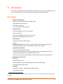
xPico Wi-Fi Embedded Device Server User Guide Part Number 900-691-R Revision A July 2013 Intellectual Property © 2013 Lantronix, Inc. All rights reserved. No part of the contents of this book may be transmitted or reproduced in any form or by any means without the written permission of Lantronix. Lantronix® and xPico® are registered trademarks of Lantronix, Inc. in the United States and other countries. DeviceInstaller™ is a trademark of Lantronix, Inc. U.S. patents pending. Windows® and Internet Explorer® are registered trademarks of Microsoft Corporation. Mozilla® and Firefox® are registered trademarks of the Mozilla Foundation. Chrome™ is a trademark of Google, Inc. Wi-Fi® is a registered trademark of Wi-Fi Alliance. All other trademarks and trade names are the property of their respective holders. Warranty For details on the Lantronix warranty policy, please go to our web site at www.lantronix.com/support/warranty. Contacts Lantronix, Inc. Corporate Headquarters 167 Technology Drive Irvine, CA 92618, USA Toll Free: Phone: Fax: 800-526-8766 949-453-3990 949-453-3995 Technical Support Online: www.lantronix.com/support Sales Offices For a current list of our domestic and international sales offices, go to the Lantronix web site at www.lantronix.com/about/contact. Disclaimer The information in this guide may change without notice. The manufacturer assumes no responsibility for any errors that may appear in this guide. Revision History Date Rev. Comments July 2013 A Initial document (firmware 1.0.0.0R7). xPico® Wi-Fi® Embedded Device Server User Guide 2 Table of Contents Intellectual Property ________________________________________________________ 2 Warranty _________________________________________________________________ 2 Contacts _________________________________________________________________ 2 Disclaimer ________________________________________________________________ 2 Revision History ___________________________________________________________ 2 List of Figures _____________________________________________________________ 6 List of Tables _____________________________________________________________ 7 1: Using This Guide 8 Purpose and Audience ______________________________________________________ 8 Summary of Chapters _______________________________________________________ 8 Additional Documentation ____________________________________________________ 8 2: Introduction 10 Key Features _____________________________________________________________ 10 Protocol Support _________________________________________________________ 12 Troubleshooting Capabilities _________________________________________________ 12 Configuration Methods _____________________________________________________ 12 Addresses and Port Numbers ________________________________________________ 12 Hardware Address _____________________________________________________ 12 IP Address ___________________________________________________________ 12 Port Numbers _________________________________________________________ 12 Product Information Label ___________________________________________________ 13 3: Configuration Using Web Manager 14 Accessing Web Manager ___________________________________________________ 14 Status Page ______________________________________________________________ 15 Web Manager Components _________________________________________________ 16 Navigating Web Manager ___________________________________________________ 16 4: Network Settings 18 Network 1 Interface (ap0) Configuration ________________________________________ 18 To Configure Network 1 Interface Settings ___________________________________ 18 To View Network 1 Interface Status ________________________________________ 19 Network 1 (ap0) Link Settings ________________________________________________ 19 To Configure Network 1 Link Settings ______________________________________ 19 To View Network 1 Link Status ____________________________________________ 20 Network 2 (wlan0) Interface Configuration ______________________________________ 20 To Configure Network 2 Interface Settings ___________________________________ 21 xPico® Wi-Fi® Embedded Device Server User Guide 3 To View Network 2 Interface Status ________________________________________ 21 Network 2 (wlan0) Link Status _______________________________________________21 To View Network 2 Link Status ____________________________________________ 21 WLAN Profiles ____________________________________________________________ 22 To Configure WLAN Profiles _____________________________________________ 22 To Configure WLAN Profile Settings _______________________________________ 23 WLAN Quick Connect ______________________________________________________ 24 To Configure WLAN Quick Connect ________________________________________ 24 5: Line and Tunnel Settings 26 Line Settings _____________________________________________________________ 26 To Configure Line Settings _______________________________________________26 To View Line Status ____________________________________________________ 27 Tunnel Settings ___________________________________________________________ 27 Line Settings __________________________________________________________ 27 To View Tunnel Serial Settings ___________________________________________ 27 Packing Mode _________________________________________________________ 28 To Configure Tunnel Packing Mode Settings _________________________________ 29 Accept Mode __________________________________________________________ 29 To Configure Tunnel Accept Mode Settings __________________________________ 30 Disconnect Mode ______________________________________________________ 30 To Configure Tunnel Disconnect Mode Settings ______________________________ 31 Statistics _____________________________________________________________ 31 To View Tunnel Statistics ________________________________________________ 31 6: Services Settings 32 HTTP Settings ____________________________________________________________ 32 To Configure HTTP Settings _____________________________________________ 32 To View HTTP Status ___________________________________________________ 32 To Configure HTTP Access Control ________________________________________ 33 7: Maintenance and Diagnostics Settings 34 Filesystem Settings ________________________________________________________ 34 Filesystem ___________________________________________________________ 34 To View Filesystem Statistics _____________________________________________ 34 System Settings __________________________________________________________ 34 System Management ___________________________________________________ 35 To Reboot or Restore Factory Defaults _____________________________________ 35 Admin User ___________________________________________________________ 35 To Configure Admin User on the Device ____________________________________ 35 xPico® Wi-Fi® Embedded Device Server User Guide 4 8: Advanced Settings 36 XML Import and XML Export _________________________________________________ 36 To Import or Export XML Configuration _____________________________________ 36 9: Updating Firmware 37 Obtaining Firmware ________________________________________________________ 37 Loading New Firmware through Web Manager __________________________________ 37 Appendix A: Technical Support 39 Appendix B: Compliance 40 Federal Communication Commission Interference Statement _______________________ 42 Radiation Exposure Statement ____________________________________________ 42 End Product Labeling ___________________________________________________ 43 Manual Information To the End User _______________________________________ 43 Industry Canada Statement _________________________________________________ 43 Radiation Exposure Statement ____________________________________________ 43 Déclaration d'exposition aux radiations _____________________________________ 43 End Product Labeling ___________________________________________________ 44 Plaque signalétique du produit final ________________________________________ 44 Manual Information To the End User _______________________________________ 44 Manuel d'information à l'utilisateur final _____________________________________ 45 Antenna Requirement ___________________________________________________ 45 Appendix C: Binary to Hexadecimal Conversions 47 Converting Binary to Hexadecimal ____________________________________________ 47 Conversion Table ______________________________________________________ 47 Scientific Calculator ____________________________________________________ 47 xPico® Wi-Fi® Embedded Device Server User Guide 5 List of Figures Figure 2-2 xPico Wi-Fi Product Label ________________________________________________ 13 Figure 3-1 Status Page ____________________________________________________________ 15 Figure 3-2 Components of the Web Manager Page ______________________________________ 16 Figure 9-1 Uploading New Firmware _________________________________________________ 37 xPico® Wi-Fi® Embedded Device Server User Guide 6 List of Tables Table 2-1 Recommended Operating Conditions ________________________________________ 11 Table 3-3 Web Manager Pages _____________________________________________________ 17 Table 4-1 Network Interface Settings _________________________________________________ 18 Table 4-2 Network 1 (ap0) Link Settings ______________________________________________ 19 Table 4-3 Network Interface Settings _________________________________________________ 20 Table 4-4 Creating, Deleting or Enabling WLAN Profiles __________________________________ 22 Table 4-5 WLAN Profile Basic Settings _______________________________________________23 Table 4-6 WLAN Profile Security Settings _____________________________________________ 23 Table 4-7 WLAN Profile Advanced Settings ___________________________________________ 24 Table 4-8 WLAN Quick Connect ____________________________________________________ 25 Table 5-1 Line Configuration Settings ________________________________________________ 26 Table 5-2 Tunnel Line Settings _____________________________________________________ 27 Table 5-3 Tunnel Packing Mode Settings _____________________________________________ 28 Table 5-4 Tunnel Accept Mode Settings ______________________________________________ 29 Table 5-5 Tunnel Disconnect Mode Settings ___________________________________________ 31 Table 6-1 HTTP Settings __________________________________________________________ 32 Table 6-2 HTTP Access Control ____________________________________________________ 32 Table 7-1 File Display Settings _____________________________________________________ 34 Table 7-2 Management Settings ____________________________________________________ 35 Table 7-3 Admin User Settings _____________________________________________________ 35 Table 2-4 Europe – EU Declaration of Conformity _______________________________________ 41 Table 2-5 Approved Antenna(s) List _________________________________________________ 45 xPico® Wi-Fi® Embedded Device Server User Guide 7 1: Using This Guide Purpose and Audience This guide provides the information needed to configure, use, and update the xPico® Wi-Fi® embedded device server. It is intended for software developers and system integrators who are embedding this product into their designs. Summary of Chapters The remaining chapters in this guide include: Chapter Description 2: Introduction Main features of the product and the protocols it supports. Includes technical specifications. 3: Configuration Using Web Manager Instructions for accessing Web Manager and using it to configure settings for the device. 4: Network Settings Instructions for configuring network settings. 5: Line and Tunnel Settings Instructions for configuring line and tunnel settings. 6: Services Settings Instructions for configuring HTTP settings. 7: Maintenance and Diagnostics Settings Instructions to maintain the xPico Wi-Fi, view statistics, files, and diagnose problems. 8: Advanced Settings Provides additional information on security settings available. 9: Updating Firmware Instructions for obtaining the latest firmware and updating the xPico Wi-Fi. Appendix A: Technical Support Instructions for contacting Lantronix Technical Support. Appendix B: Compliance Lantronix compliance information. Appendix C: Binary to Hexadecimal Conversions Instructions for converting binary values to hexadecimals. Additional Documentation Visit the Lantronix Web site at www.lantronix.com/support/documentation for the latest documentation and the following additional documentation. Document Description xPico Wi-Fi Embedded Device Server Integration Guide Information about the xPico Wi-Fi hardware, testing the device server using the demonstration board, and integrating the unit into your product. xPico Wi-Fi Evaluation Kit Embedded Device Server Quick Start Guide Instructions for getting the xPico Wi-Fi up and running. xPico® Wi-Fi® Embedded Device Server User Guide 8 1: Using This Guide Document (continued) Description xPico Wi-Fi Evaluation Kit Embedded Device Server User Guide Information needed to use the xPico Wi-Fi on the evaluation board. Com Port Redirector Quick Start Instructions for using the Lantronix Windows-based utility to create and Online Help virtual com ports. xPico® Wi-Fi® Embedded Device Server User Guide 9 2: Introduction This chapter summarizes the basic information and features of the xPico Wi-Fi embedded device server. It provides an overview of key features and describes suitable applications. Key Features Wireless LAN Interface: IEEE 802.11 b/g and IEEE 802.11n (single stream) WLAN interface (2.4 GHz only) IEEE 802.11 d/h/i/j/k/w/r u.FL connector for external antenna Serial Interface: Two Serial CMOS Ports (3.3V, 5V tolerant)1 1200 to 921.6Kbps Flow control: XON/XOFF, RTS/CTS (Line 1 only) Lantronix tunneling application (Line 1 only) Host Interface: Dual Serial Port, SPI, USB2.0 (device) 8 GPIO Network Protocols: TCP/IP, UDP/IP, DHCP Server (software-enabled Access Point interface), ARP, ICMP, DHCP Client (WLAN interface), Auto-IP, DNS Networking Capabilities: Soft Access Point with DHCP Server Roaming: continually tracks Wi-Fi signal strength within range, resulting in smooth and automatic transition between access points without delay. QuickConnect: Dynamic Profiles facilitate easy and rapid connections to access points Management and Control: Web Server CLI (Serial Monitor Port) XML Configuration Import and Export (XCR, XML Status Export [XSR]) Field upgradable firmware (OTA) Security: IEEE 802.11i Support – WPA-Personal, WPA2-Personal 256-bit AES Encryption 1. For xPico Wi-Fi 5V tolerant pins, in order to sustain a voltage higher than Vcc+0.3, the internal pull up/pull down resistors must be disabled. xPico® Wi-Fi® Embedded Device Server User Guide 10 2: Introduction Architecture: ARM Cortex-M3 class processor with on-chip Flash and SRAM 1MB Flash and 128KB SRAM SPI Flash 1 MB Power: Input Voltage: 3.3VDC Table 2-1 Recommended Operating Conditions Parameter Symbol Typical Max Units TX Power @ 16.5dBm, 802.11b, 11Mbps ICC Min 330 380 mA TX Power @ 15dBm, 802.11g, 6Mbps ICC 300 345 mA TX Power @ 13dBm, 802.11g, 54Mbps ICC 255 295 mA TX Power @ 14.5dBm, 802.11n, MCS0 ICC 290 335 mA TX Power @ 12dBm, 802.11n, MCS7 ICC 230 265 mA RX Power @ 802.11b, 11Mbps ICC 125 150 mA RX Power @ 802.11g, 54Mbps ICC 125 150 mA RX Power @ 802.11n, MCS7 ICC 125 150 mA Power Management State 1 @ 25°C ICC 6 μA Power Management State 1 @ +85°C ICC 12 μA Power Management State 1 @ -40°C ICC 5 μA Physical Interface: 40-pin Board-to-Board SMT Connector Environmental: Operating Temperature: –40°to +85° C Storage Temperature : –40°to +85° C Relative Humidity: 0% to 90% non-condensing Certifications: FCC, IC, EU, Japan, UL, CE Packaging: Dimensions: 24mm (L) x 16.5mm (W) x 5.64mm (H) Weight: 2.5g Warranty: 5-Year Limited xPico® Wi-Fi® Embedded Device Server User Guide 11 2: Introduction Protocol Support The xPico Wi-Fi intelligent gateway contains a full-featured IP stack. Supported protocols include: IEEE 802.11 b/g and IEEE 802.11n (single stream) WLAN interface (2.4 GHz only) 802.11i - WPA-Personal, WPA2-Personal Soft-AP with DHCP Server HTTP Server TCP/IP, UDP/IP, DHCP Server (Software enabled Access Point interface), ARP, ICMP, DHCP Client (WLAN interface), Auto-IP, DNS Troubleshooting Capabilities The xPico Wi-Fi offers the abilty to view system log messages. Configuration Methods After installation, the xPico Wi-Fi embedded device server requires configuration. For the unit to operate correctly on a network, it must have a unique IP address on the network. These methods may be used for logging into the xPico Wi-Fi and assigning IP addresses and other configurable settings: Web Manager: View and configure settings easily through a web browser using the Lantronix Web Manager. See “Configuration Using Web Manager” on page 14. XML: The xPico Wi-Fi supports XML import and XML export through a terminal emulator software such as Tera Term. See “XML Import and XML Export” on page 36. Addresses and Port Numbers Hardware Address The hardware address is also referred to as the physical address or MAC address. Sample hardware address: 00-80-A3-FF-FF-FF 00:80:A3:FF:FF:FF IP Address Every device connected to an IP network must have a unique IPv4 address. This address references the specific unit. Port Numbers TCP Port 80: HTTP Server (Web Manager configuration) TCP Port 10001: Tunnel xPico® Wi-Fi® Embedded Device Server User Guide 12 2: Introduction Product Information Label The product information label on the unit contains the following information about the specific unit: Lantronix Datamatrix Code Product Revision Part Number Serial Number Hardware Address (MAC Address) Manufacturing Date Code Figure 2-2 xPico Wi-Fi Product Label xPico® Wi-Fi® Embedded Device Server User Guide 13 3: Configuration Using Web Manager This chapter describes how to configure the xPico Wi-Fi embedded device server using Web Manager, the Lantronix browser-based configuration tool. The unit’s configuration is stored in nonvolatile memory and is retained without power. All changes take effect immediately, unless otherwise noted. It contains the following sections: Accessing Web Manager Web Manager Components Navigating Web Manager Accessing Web Manager To access Web Manager, perform the following steps: 1. Open a standard web browser. Lantronix supports the latest version of Internet Explorer, Mozilla Firefox, Safari or Chrome. 2. Enter the IP address or hostname of the xPico Wi-Fi in the address bar. The IP address may have been assigned manually or automatically by DHCP. 3. Enter your username and password.The factory-default username is “admin” and the password is “PASSWORD” (all capitalized). The Status web page displays product information, network settings, line settings, and tunneling settings. xPico® Wi-Fi® Embedded Device Server User Guide 14 3: Configuration Using Web Manager Status Page The Status page is the first to appear after you log into Web Manager. The Status page also appears when you click Status tab in Web Manager. Figure 3-1 Status Page xPico® Wi-Fi® Embedded Device Server User Guide 15 3: Configuration Using Web Manager Web Manager Components The layout of a typical Web Manager page is below. Figure 3-2 Components of the Web Manager Page Items to configure Links to subpages Header Menu Bar Footer Configuration and/or Status Area Information and Help Area Navigating Web Manager The Web Manager provides an intuitive point-and-click interface. A menu bar on the left side of each page provides links you can click to navigate between pages. Some pages are read-only, while others let you change configuration settings. Note: There may be times when you must reboot the xPico Wi-Fi for the new configuration settings to take effect. The chapters that follow indicate when a change requires a reboot. Anytime you reboot the unit, this operation will take some time to complete. Please wait a minimum of 10-20 seconds after rebooting the unit before attempting to make any subsequent connections. xPico® Wi-Fi® Embedded Device Server User Guide 16 3: Configuration Using Web Manager Table 3-3 Web Manager Pages Web Manager Page Description See Page Status Shows product information, network, line status, and tunneling settings. 15 Filesystem Shows file system statistics and lets you perform filesystem operations. 34 HTTP Shows HyperText Transfer Protocol (HTTP) status and lets you change the current configuration and authentication settings. 32 Line Shows statistics and lets you change the current configuration and Command 26 mode settings of a serial line. Network Shows status and lets you configure the network interface. System Lets you reboot the device, restore factory defaults and upload new firmware. 34 Tunnel Lets you change the current configuration settings for an incoming tunnel connection. 27 WLAN Profiles Lets you view, edit, delete and create a WLAN profile on a device. 22 Quick Connect 18 Lets you scan for available network in vicinity and create WLAN profile 24 easily. xPico® Wi-Fi® Embedded Device Server User Guide 17 4: Network Settings The Network Settings show the status of the Software enabled Access Point (SoftAP) or WLAN interface/link and let you configure the settings on the device. Interface settings are related to the configuration of the IP and related protocols. Link settings are related to the physical link connection, which carries the IP traffic. The xPico Wi-Fi embedded device server contains two network interfaces. The Software enabled Access Point interface is also called interface 1 or ap0, and the WLAN interface is called interface 2 or wlan0. Note: All network settings require a reboot to take effect. Wait a minimum of 10-20 seconds after rebooting the unit before attempting to make any subsequent connections. Network 1 Interface (ap0) Configuration Table 4-1 shows the network interface settings that can be configured. These settings apply to the Software enabled Access Point (ap0) interface. Table 4-1 Network Interface Settings Network (ap0) Interface Settings Description State Click to enable or disable the SoftAP. If enabled, the DHCP server will assign IP addresses to the SoftAP’s clients. The DHCP Server manages up to 4 client IP addresses and the first IP address will be the next IP address after the Access Point’s IP address (see IP Address description below). Note: A DHCP lease lasts for a day. If the IP network is managed manually, a static IP can be used outside the range of the DHCP address pool. IP Address Enter the static IP address to use for the interface. You may enter it in one of the following ways: Alone (i.e., 192.168.1.1) In CIDR format (i.e., 192.168.1.1/24) With an explicit mask (i.e., 192.168.1.1 255.255.255.0) To Configure Network 1 Interface Settings Using Web Manager To modify Software enabled Access Point (ap0) settings, go to Network on the menu and select Network 1 -> Interface -> Configuration. Using XML via CLI Include in your file: <configgroup name = "Interface" instance = "ap0"> xPico® Wi-Fi® Embedded Device Server User Guide 18 4: Network Settings To View Network 1 Interface Status Using Web Manager In Network Interface Status, you can view both the current operational settings as well as the settings that would take effect upon a device reboot. To view current access point (ap0) settings, go to Network on the menu and select Network 1 -> Interface -> Status. Using XML via CLI Look for the status header: <statusgroup name = "Interface" instance = "ap0"> Network 1 (ap0) Link Settings Physical link parameters can be configured for an access point (ap0) Network Interface (see Table 4-2). Table 4-2 Network 1 (ap0) Link Settings Network 1 (ap0) Link Settings Description Network Name (SSID) Specify the name of the wireless network (SSID) for the SoftAP. Channel Specify the channel for the SoftAP. Suite Specify the security suite to be used for the SoftAP. None = no authentication or encryption method will be used. WPA = WiFi Protected Access WPA2 = Robust Secure Network. Encryption Select one or more encryption types, listed from strongest to least strong. CCMP = Uses AES as basis and is the strongest encryption option. TKIP = Uses WEP as the basis, but adds extra checks and variations for added protection. Passphrase Select the passphrase which may consist of up to 63 characters. Note: This configuration option becomes available only when suites WPA or WPA2 are selected. Lantronix recommends using a passphrase of 20 characters or more for maximum security. Spaces and punctuation characters are permitted. The passphrase input is not the same as ASCII input (as used on some products.) ASCII is translated directly into hexadecimal bytes according to the ASCII table, while a possibly larger passphrase is hashed into a key and provides better security through a larger range of key values. To Configure Network 1 Link Settings Using Web Manager To modify network (ap0) Link information, click Network on the menu and select Network 1 > Link > Configuration. xPico® Wi-Fi® Embedded Device Server User Guide 19 4: Network Settings Using XML via CLI Include in your file: <configgroup name = "Access Point" instance = "ap0"> To View Network 1 Link Status Using Web Manager In Network Link Status, you can view the current operational settings. To view current network (ap0) settings, go to Network on the menu and select Network 1 -> Link -> Status. Using XML via CLI Look for the status header: <statusgroup name = "Interface" instance = "ap0"> Network 2 (wlan0) Interface Configuration This page is used to configure the network 2 interface on the device. To see the effect of these items after a reboot, view the Status page. Table 4-3 Network Interface Settings Network Interface Settings Description State Click to enable or disable the WLAN interface. DHCP Client Select to turn the DHCP client either On or Off. If enabled, any configured IP address, network mask, gateway or hostname will be ignored. DHCP will autodiscover and eclipse those configured items. When DHCP fails to discover an IP address, a new address will automaticaly be generated using AutoIP. This address will be within the 169.254.x.x space. At boot up, after the physical link is up, the xPico Wi-Fi will attempt to obtain IP settings from a DHCP server and will periodically renew these settings with the server. Note: Click renew on Interface Status page to force DHCP lease renewal. IP Address Enter the static IP address to use for the interface. You may enter it in one of the following ways: Alone (i.e., 192.168.1.1) In CIDR format (i.e., 192.168.1.1/24) With an explicit mask (i.e., 192.168.1.1 255.255.255.0) Note: This setting will be used if Static IP is active (DHCP Client is Off). Default Gateway Enter the IP address of the router for this network. Note: This setting will be used if Static IP is active (DHCP Client is Off). Hostname Enter the hostname for the interface. It must begin with a letter, continue with a letter, number or hyphen, and must end with a letter or number. The device will not register the hostname with a DNS server until the next reboot. Primary DNS Enter the IP address of the primary Domain Name Server. Note: This setting will be used when Static IP is active. xPico® Wi-Fi® Embedded Device Server User Guide 20 4: Network Settings Network Interface Settings (continued) Description Secondary DNS Enter the IP address of the secondary Domain Name Server. Note: This setting will be used when Static IP is active. To Configure Network 2 Interface Settings Using Web Manager To modify network 2 WLAN interface information, click Network on the menu and select Network 2 > Interface > Configuration. Using XML via CLI Include in your file: <configgroup name = "Interface" instance = "wlan0"> To View Network 2 Interface Status Using Web Manager In Network Interface Status, you can view both the current operational settings as well as the settings that would take affect upon a device reboot. To view current access piont (ap0) settings, go to Network on the menu and select Network 2 -> Interface -> Status. Using XML via CLI Look for the status header: <statusgroup name = "Interface" instance = "wlan0"> Network 2 (wlan0) Link Status This page shows status of a Link on the device. To View Network 2 Link Status Using Web Manager To view network 2 link interface information, click Network on the menu and select Network 2 > Link > Status. Using XML via CLI Include in your file: <configgroup name = "Interface" instance = "wlan0"> xPico® Wi-Fi® Embedded Device Server User Guide 21 4: Network Settings WLAN Profiles A WLAN profile defines all of the settings necessary to establish a wireless connection with an access point (in infrastructure mode). A maximum of four profiles can exist on the xPico Wi-Fi at a time and only one profile may be active at any given time. xPico Wi-Fi supports dynamic profiles. Dynamic Profiles are the ones created via QuickConnect. WLAN Profile WEP Settings WEP is a simple and efficient security mode encrypting the data via the RC4 algorithm. However, WEP has become more vulnerable due to advances in hacking technology. State of the art equipment can find WEP keys in five minutes. For stronger security, please use WPA, or better, WPA2 with AES (CCMP). WLAN Profile WPA and WPA2 Settings WPA is a security standard specified by the WiFi Alliance and is a close derivative of an early draft of the IEEE802.11i specification. WEP was becoming vulnerable when finalizing the IEEE802.11i standard was still far away. WPA2 is WiFi’s subset of the broad IEEE802.11i standard to enforce better interoperability. The xPico Wi-Fi is compliant with both WPA2 and IEEE802.11i. To Configure WLAN Profiles You can view, edit, create or delete a WLAN profile. Using WebManager Click WLAN Profiles on the menu. Using XML via CLI Include in your file: <configgroup name = "WLAN Profile" instance = "name"> Table 4-4 Creating, Deleting or Enabling WLAN Profiles WLAN Profile Basic Settings Description Create new profile Type the name of the new profile to be created into the Create new profile field. Then, click the Submit button which appears to create the profile. Once created, the profile name may be clicked so you may edit profile settings. Delete (checkbox) Click the Delete checkbox beside the profile(s) to be deleted. Three buttons will appear: Enabled (checkbox) Click the Submit button to permanently delete profile(s). Click the Apply button to delete the profile for testing purposes. If the device reboots, this change will not be applied. Click the Cancel button to cancel this action, as desired. Click the Enabled checkbox beside the profile(s) to be enabled (or unchecked to disable). Three buttons will appear: Click the Submit button to permanently enable profile(s). Click the Apply button to enable the profile for testing purposes. If the device reboots, this change will not be applied. Click the Cancel button to cancel this action, as desired. xPico® Wi-Fi® Embedded Device Server User Guide 22 4: Network Settings WLAN Profile Basic Settings (continued) Description View or Edit (link to specific profile) Click on a specific WLAN Profile name to edit the WLAN profile basic settings. To Configure WLAN Profile Settings Using Web Manager To view or edit an existing WLAN profile, click WLAN Profiles on the menu and select an existing profile (see Table 4-5, Table 4-6 and Table 4-7). Using XML via CLI Include in your file: <configgroup name = "WLAN Profile" instance = "name"> Table 4-5 WLAN Profile Basic Settings WLAN Profile Basic Settings Description Network Name (SSID) Specify the name of the wireless network (SSID.) State Select to Enable or Disable this profile. Table 4-6 WLAN Profile Security Settings WLAN Profile Security Settings Description Suite Specify the security suite to be used for this profile. Key Size None = no authentication or encryption method will be used. WEP = Wired Equivalent Privacy WPA = WiFi Protected Access WPA2 = Robust Secure Network. Select the appropriate key size in bits. Select 40 for WEP40 and WEP64; select 104 for WEP104 and WEP128. Note: This option is available if WEP suite is selected above. TX Key Index Select one of four index listing keys for transmitting data. Reception is allowed with all four keys. Note: For operability with some products that generate four identical keys from a passphrase, this index must be one. This option is available if WEP suite is selected above. Key 1-4 Enter one or more encryption keys in hexadecimal format. Enter 10 hexadecimal digits (0-9, a-f) for WEP40 and 26 for WEP104. The configured keys are not shown for security reasons. Note: This option is available if WEP suite is selected above. Key Type Select the format of the security key. Note: This configuration option becomes available only when suites, WPA or WPA2 are selected. xPico® Wi-Fi® Embedded Device Server User Guide 23 4: Network Settings WLAN Profile Security Settings Description Password Select the password consists of up to 63 characters. Note: Lantronix recommends using a passphrase of 20 characters or more for maximum security. Spaces and punctuation characters are permitted. The passphrase input is not the same as ASCII input (as used on some products.) ASCII is translated directly into hexadecimal bytes according to the ASCII table, while a possibly larger passphrase is hashed into a key and provides better security through a larger range of key values. This configuration option becomes available only when suites, WEP, WPA or WPA2 are selected. Encryption Select one or more encryption types, listed from strongest to least strong. At least one selection will have to match the Access Points intended to connect with. CCMP = Uses AES as basis and is the strongest encryption option. TKIP = Uses WEP as the basis, but adds extra checks and variations for added protection. Note: In case the encryption settings on the Access Point(s) can still be chosen, the capabilities of the Access Point(s) and the other clients that need to use the network need to be taken into account.This configuration option becomes available only when suites WPA or WPA2 are selected. Table 4-7 WLAN Profile Advanced Settings WLAN Profile Advanced Settings Description TX Power Maximum Specify the maximum transmission output power in dBm. Power Management Select to Enable or Disable power management, which reduces the overall power consumption of the xPico Wi-Fi unit, but can increase latency. Power Management Interval Enabled = allows the xPico Wi-Fi to turn off the receiver when it is idling. Disabled = keeps the receiver on at all times. Select number of beacons (100 msec interval) between 1 and 5. The above-mentioned latency can be up to this number “X” 100 msec. WLAN Quick Connect WLAN QuickConnect allows users to view and add up to four WLAN profiles from a list of up to 20 wireless devices sorted by RSSI. Details of the selected network are pre-populated, so little or no configuration is required by the user. To Configure WLAN Quick Connect Using Web Manager To view or edit an existing WLAN Quick Connect settings, click QuickConnect on the menu. Using XML via CLI Not applicable. xPico® Wi-Fi® Embedded Device Server User Guide 24 4: Network Settings Table 4-8 WLAN Quick Connect WLAN Quick Connect Settings Description Network Name (search field) Enter a network name and click Scan to search for a network. Scan “<network SSID>” Perform a scan for devices within range of the xPico Wi-Fi. Including the optional network SSID limits the scan to devices configured with the specified network SSID. Omitting the network SSID performs a scan for all devices in range. Network Name (link) Lists the SSID of a network. Click a specific Network Name to display the Quick Connect profile. If you provide the Password for a specific Quick Connect Profile, you can add that profile to your list of WLAN Profiles. Up to four WLAN profiles may be added, and only one may be connected at any given time. BSSID Lists the basic service set identifier. This is a unique 48-bits address that identifies the access point that creates the wireless network. CH Provides the channel number of a network. RSSI Displays an instantaneous value indicating the signal strength of the network. The best to worst signal strength is indicated by green, yellow and red respectively. Note: RSSI reported in scan results is a single sampling. Security Suite Lists the security suite of a network (e.g., WEP, WPA, WPA2). xPico® Wi-Fi® Embedded Device Server User Guide 25 5: Line and Tunnel Settings The xPico Wi-Fi embedded device server has one tunnel through which you may view statistics or configure the Accept Mode. The device has two lines and the second line is available for diagnostic and maintenance. Line Settings The Line Settings allow configuration of the serial lines (ports). Some settings may be specific to only certain lines. Such settings are noted below. Note: The settings described below apply to both Line 1 and Line 2 unless otherwise noted. Table 5-1 Line Configuration Settings Line Settings Description Name Enter a name or short description for the line, if desired. By default, there is no name specified. A name that contains white space must be quoted. State Select to Enable or Disable the operational state of the Line. The default is an enabled state. Protocol Set the operational protocol for the Line. The default is Tunnel for Line 1 and Command Line for Line 2. Choices are: Baud Rate None Tunnel = Serial-Network tunneling protocol (Line 1 only) Trouble Log Command Line Set the Baud Rate (speed) of the Line. The default is 9600. Any set speed between 1200 and 921600 may be selected: 1200, 2400, 4800, 9600, 19200, 38400, 57600, 115200, 230400, 460800, 921600. Parity Set the Parity of the Line. The default is None. Data Bits Set the number of data bits for the Line. The default is 8. Stop Bits Set the number of stop bits for the Line. The default is 1. Flow Control Set the flow control for the Line. The default is None. Hardware flow control is only supported on Line 1. Gap Timer Set the Gap Timer delay to Set the number of milliseconds to pass from the last character received before the driver forwards the received serial bytes. By default, the delay is four character periods at the current baud rate (minimum 1 msec). Gap Timer range is 1 to 5000 milliseconds. Threshold Set the number of threshold bytes which need to be received in order for the driver to forward received characters. Default value is 56 bytes. To Configure Line Settings Note: The following section describes the steps to view and configure Line 1 settings; these steps apply to other line instances of the device. xPico® Wi-Fi® Embedded Device Server User Guide 26 5: Line and Tunnel Settings Using Web Manager To configure a specific line, click Line in the menu and select Line 1 -> Configuration (Table 5-1). Using XML via CLI Include in your file: <configgroup name = "Line" instance = "1"> To View Line Status Using Web Manager To view statistics for a specific line, click Line in the menu and select Line 1 -> Status. Using XML via CLI Look for the status header: <statusgroup name = "Line" instance = "1"> Tunnel Settings Tunneling allows serial devices to communicate over a network, without “being aware” of the devices which establish the network connection between them. Tunneling parameters are configured using the Tunnel menu and submenus. The Tunnel settings allow you to configure how the Serial-Network tunneling operates. Tunneling is available only on Line 1. Line Settings These serial settings for the tunnel apply to the Serial Line interface. The Line Settings and Protocol are displayed for informational purposes and must be configured from the Line settings. Table 5-2 Tunnel Line Settings Tunnel Serial Settings Description Line Settings Line Settings information here is display only. Go to the section, To Configure Line Settings to modify these settings. Protocol Protocol information here is display only. Go to the section, To Configure Line Settings to modify these settings. To View Tunnel Serial Settings Using Web Manager To view the Serial Settings for a specific tunnel, click Tunnel in the menu and select Tunnel 1 -> Line Settings. Using XML via CLI Include in your file: <configgroup name = "Tunnel Line" instance = "1"> xPico® Wi-Fi® Embedded Device Server User Guide 27 5: Line and Tunnel Settings Packing Mode With Packing, data from the serial Line is not sent over the network immediately. Instead, data is queued and sent in segments, when either the timeout or byte threshold is reached. Packing applies to both Accept and Connect Modes. Table 5-3 Tunnel Packing Mode Settings Tunnel Packing Mode Settings Mode Description Configure the Tunnel Packing Mode. Choices are: Threshold Disable = Data not packed. Timeout = data sent after timeout occurs. Send Character = data sent when the Send Character is read on the Serial Line. Set the threshold (byte count). If the received serial data reaches this threshold, then the data will be sent on the network. Valid range is 100 to 1450 bytes. Default is 512. Note: This configuration option becomes available when Timeout is the selected Mode. Timeout Set the timeout value, in milliseconds, after the first character is received on the serial line, before data is sent on the network. Valid range is 1 to 30000 milliseconds. Default is 1000. Note: This configuration option becomes available when Timeout is the selected Mode. Send Character Enter Control Characters in any of the following forms: <control>J 0xA (hexadecimal) \10 (decimal) If used, the Send Character is a single printable character or a control character that, when read on the Serial Line, forces the queued data to be sent on the network immediately. Note: This configuration option becomes available when Send Character is the selected Mode. Trailing Character Enter Control Characters in any of the following forms: <control>J 0xA (hexadecimal) \10 (decimal). If used, the Trailing Character is a single printable character or a control character that is injected into the outgoing data stream right after the Send Character. Disable the Trailing Character by blanking the field (setting it to <None>). Note: This configuration option becomes available when Send Character is the selected Mode. xPico® Wi-Fi® Embedded Device Server User Guide 28 5: Line and Tunnel Settings To Configure Tunnel Packing Mode Settings Using Web Manager To configure the Packing mode for a specific tunnel, click Tunnel in the menu and select Tunnel 1 -> Packing. Using XML via CLI Include in your file: <configgroup name = "Tunnel Packing" instance = "1"> Accept Mode In Accept mode, the xPico Wi-Fi listens (waits) for incoming connections from the network. A remote node on the network initiates the connection. The configurable local port is the port the remote device connects to for this connection. There is no remote port or address. The default local port is 10001. Serial data can still be received while waiting for a network connection, keeping in mind serial data buffer limitations. Table 5-4 Tunnel Accept Mode Settings Tunnel Accept Mode Settings Mode Description Set the method used to start a tunnel in Accept mode. Choices are: Start Character Disable = do not accept an incoming connection. Always = accept an incoming connection (default). Any Character = start waiting for an incoming connection when any character is read on the serial line. Start Character = start waiting for an incoming connection when the start character for the selected tunnel is read on the serial line. Enter the start character which will enable the tunnel to listen for a network connection. The start character may be designated as a single printable character or as a control character. Control characters may be input in any of the following forms: <control>J or 0xA (hexadecimal) or \10 (decimal) Note: This configuration option becomes available when Start Character is the selected Mode. Flush Start Character Enable or disable the flush start character: Enabled = prevents forwarding of a start character from the Line into the network. Disabled = the flush start character allows forwarding of a start character from the line into the network. Note: This configuration option becomes available when Start Character is the selected Mode. Local Port Set the port number for use as the network local port. The default local port is 10001. Protocol Select the TCP type for use with Accept Mode. xPico® Wi-Fi® Embedded Device Server User Guide 29 5: Line and Tunnel Settings Tunnel Accept Mode Settings (continued) Flush Line Description Set whether the serial line data buffer is flushed upon a new network connection. Choices are: Block Line Set whether Block Line is enabled for debugging purposes. Choices are: Block Network Enabled = if Enabled, incoming characters from the serial line will not be forwarded to the network. Instead, they will be buffered and will eventually flow off the serial line if hardware or software flow control is configured. Disabled = this is the default setting; incoming characters from the Serial Line are sent into the network. Any buffered characters are sent first. Set whether Block Network is enabled for debugging purposes. Choices are: Password Enabled = serial data buffer is flushed on network connection Disabled = serial data buffer is not flushed on network connection (default) Enabled = if Enabled, incoming characters from the network will not be forwarded to the Serial Line. Instead, they will be buffered and will eventually flow off the network side. Disabled = this is the default setting; incoming characters from the network are sent on the Serial Line. Any buffered characters are sent first. Enter a password. This password can be up to 31 characters in length and must contain only alphanumeric characters and punctuation. When set, clients must send the correct password string to the unit within 30 seconds from opening network connection in order to enable data transmission. The password sent to the unit must be terminated with one of the following: 0A (Line Feed) 00 (Null) 0D 0A (Carriage Return/Line Feed) 0D 00 (Carriage Return/Null) If, Prompt for Password is set to Enabled and a password is provided, the user will be prompted for the password upon connection. To Configure Tunnel Accept Mode Settings Using Web Manager To configure the Accept Mode for a specific tunnel, click Tunnel in the menu and select Tunnel 1 -> Accept. Using XML via CLI Include in your file: <configgroup name = "Tunnel Accept" instance = "1"> Disconnect Mode Specifies the optional conditions for disconnecting any Accept Mode connection that may be established. If any of these conditions are selected but do not occur and the network disconnects from the device, a Connect Mode connection will attempt to reconnect. However, if none of these conditions are selected, a closure from the network is taken as a disconnect. xPico® Wi-Fi® Embedded Device Server User Guide 30 5: Line and Tunnel Settings Table 5-5 Tunnel Disconnect Mode Settings Tunnel Disconnect Mode Settings Description Stop Character Enter the Stop Character which when received on the Serial Line, disconnects the tunnel. The Stop Character may be designated as a single printable character or as a control character. Control characters may be input in any of the following forms: <control>J or 0xA (hexadercimal) or \10 (decimal). Disable the Stop Character by blanking the field to set it to <None>. Timeout Enter the number of milliseconds a tunnel may be idle before disconnection. The value of zero disables the idle timeout. Flush Line Set whether to flush the Serial Line when the Tunnel is disconnected. Choices are: Enabled Disabled (default) To Configure Tunnel Disconnect Mode Settings Using Web Manager To configure the Disconnect Mode for a specific tunnel, click Tunnel in the menu and select Tunnel 1 -> Disconnect. Using XML via CLI Include in your file: <configgroup name = "Tunnel Disconnect" instance = "1"> Statistics Tunnel statistics contains data counters, error counters, connection time and connection information. Statistics are available at each individual connection and aggregated across all connections. To View Tunnel Statistics Using Web Manager To view statistics for a specific tunnel, click Tunnel in the menu and select the Tunnel 1 -> Statistics. Using XML via CLI Look for the status header: <statusgroup name = "line" instance = "1"> xPico® Wi-Fi® Embedded Device Server User Guide 31 6: Services Settings HTTP Settings Hypertext Transfer Protocol (HTTP) is the transport protocol for communicating hypertext documents on the Internet. HTTP defines how messages are formatted and transmitted. It also defines the actions web servers and browsers should take in response to different commands. HTTP Authentication enables the requirement of usernames and passwords for access to the device. Table 6-1 HTTP Settings HTTP Settings Description State Select to enable or disable the HTTP server: Port Enabled (default) Disabled Enter the port for the HTTP server to use. The default (80) will be restored when the field is cleared. To Configure HTTP Settings Using Web Manager To configure HTTP settings, click HTTP in the menu and select Configuration. Using XML via CLI Include in your file: <configgroup name = "HTTP Server"> To View HTTP Status Using Web Manager To view HTTP status, click HTTP in the menu and select Status. Using XML via CLI Look for the status header: <statusgroup name = "HTTP Server"> Table 6-2 HTTP Access Control HTTP Access Control Settings Description URI Displays the root of the Uniform Resource Identifier (URI) to apply access control settings. Note: The URI must begin with ‘/’ to refer to the entire filesystem. xPico® Wi-Fi® Embedded Device Server User Guide 32 6: Services Settings HTTP Access Control Settings (continued) Auth Type Description Select the authentication type: Users None: no authentication is necessary. Basic: encodes passwords using Base64. Displays the username allowed to access the configured URI. To Configure HTTP Access Control Using Web Manager To configure HTTP Access Control, click HTTP in the menu and select Access Control. Using XML via CLI Include in your file: <configgroup name = "HTTP Server Access Control" instance=”1”> xPico® Wi-Fi® Embedded Device Server User Guide 33 7: Maintenance and Diagnostics Settings Filesystem Settings Use the Filesystem to view Statistics. A user may also compact or format the Filesystem. The xPico Wi-Fi embedded device server uses an EXT3 flash file system to store files. This is a journalled file system, which means that changes to the file system are recorded before the actual changes themselves are made. In the event of power loss, the use of journaling can usually recover from changes that had been started but not completed. Some file systems may contain a 'lost+found' directory. In the event of power loss in the midst of file system I/O, file data that cannot be fully recovered will be placed in this directory. It is recommended to always restart the system from the Web Manager application. Note: It is recommended to always use the Web Manager application to shutdown/ restart the system. Filesystem Table 7-1 File Display Settings File Display Commands Description Format Format the Filesystem and remove all data. Compact Compact the Filesystem to erase Flash and copy files. To View Filesystem Statistics Using Web Manager To view, compact or format existing files and file contents, click FIlesystem in the menu. Using XML via CLI Look for the status header: <statusgroup name = "Filesystem”> System Settings The xPico Wi-Fi System settings allow for rebooting the device, restoring factory defaults, updating passwords, and uploading new firmware. Note: Anytime you reboot the unit, this operation will take some time to complete. Please wait a minimum of 10-20 seconds after rebooting the unit before attempting to make any subsequent connections. xPico® Wi-Fi® Embedded Device Server User Guide 34 7: Maintenance and Diagnostics Settings System Management Table 7-2 Management Settings System Settings Description Reboot (button) Reboots the device. When rebooted, your browser should be refreshed and redirected to the main status page after 30 seconds. Note: The redirect will not work as expected if the IP address of the devices changes after reboot. After setting the configuration back to the factory defaults, the device will automatically be rebooted. If web manager is access through SoftAP, your connection to SofAP may be dropped when device reboots. Factory Defaults (button) Restores the device to the original factory settings. All configuration will be lost. The xPico Wi-Fi automatically reboots upon setting back to the defaults. Firmware Upload (button) Device will reboot to the Over-The-Air (OTA) firmware upgrade application to continue the operation. Note: Go to Chapter 9: Updating Firmware for directions on uploading new firmware. To Reboot or Restore Factory Defaults Using Web Manager To access the area with options to reboot, restore to factory defaults, upload new firmware, click System in the menu and select Management. Using XML via CLI Not applicable. Admin User Table 7-3 Admin User Settings System Settings Description Password Enter a new password and click Submit. Users will need to log in again after changing the password. To Configure Admin User on the Device Using Web Manager To access the area with options to reboot, restore to factory defaults, upload new firmware, click System in the menu and select Admin User. Using XML via CLI Look for the status header: <configgroup name = "Users" instance=”admin”> xPico® Wi-Fi® Embedded Device Server User Guide 35 8: Advanced Settings XML Import and XML Export The xPico Wi-Fi embedded device server allows for the configuration of devices by using XML configuration records (XCRs). You can export an existing configuration for use on other xPico WiFi devices or import a saved configuration file. Note: The xPico Wi-Fi module itself only supports serial TTL signaling on both Lines. If used with the evaluation board (see the xPico Embedded Device Server Evaluation Kit User Guide), then Line 2 may be routed through a serial-to-USB converter via jumper settings. To Import or Export XML Configuration 1. Connect the xPico Wi-Fi embedded device server to a PC using: - A null modem cable for line 1. - A USB cable for line 2. The USB driver will automatically install into your PC. 2. Configure command line on line and select hardware or software flow control. Note: If you are using line 2, select software flow control as hardware flow control is not supported. 3. Open a terminal emulator from the PC, e.g., Tera Term version 4.58. 4. Select the Com port or USB serial port and set the serial settings, on the terminal emulator, to match the appropriate line on the device server. 5. When you see prompt ‘>’ on the terminal emulator, type 'h' to view the single character commands available. >h Single character commands: c - Dumps XML configuration with secrets; stop with any character. d - Dumps XML configuration without secrets; stop with any character. h or ? - Shows this help. s - Dumps XML status; stop with any character. t - Shows Trouble Log; stop with any character. (Paste of XML) - Imports XML configuration. 6. Type c in the terminal window prompt to get the current xPico Wi-Fi xml configuration in the form of a text dump. 7. Copy and paste the configuration text into notepad or some other basic text editor. 8. Remove all the spaces in the script within the text editor. This basic text is the exported XML configuration and is now available for copy-paste into any xPico Wi-Fi embedded device server. 9. Make any additional changes to the configuration text to modify the XML configuration. 10. Copy and paste <CR> all of the text into the terminal emulator connected to the desired xPico Wi-Fi embedded device server, to "import" the new configuration. Note: Software flow control experiences overrun above 460800 baud. xPico® Wi-Fi® Embedded Device Server User Guide 36 9: Updating Firmware Obtaining Firmware Obtain the most up-to-date firmware and release notes for the unit from the Lantronix Web site (www.lantronix.com/support/downloads/) or by using anonymous FTP (ftp://ftp.lantronix.com/). Loading New Firmware through Web Manager Upload the firmware using the device web manager System page. To upload new firmware: 1. Select System in the menu bar. The System page appears. Note: See System Settings (on page 34) for options to restore factory defaults or reboot the debice. Figure 9-1 Uploading New Firmware 2. Click Firmware Upload (under the Upload New Firmware heading) to browse to the firmware file. 3. Click OK to confirm uploading a new firmware image. A few moments will pass as the firmware upload is prepared. 4. Click Choose File to select the file and click Open. 5. Click Upgrade to install the firmware on the xPico Wi-Fi embedded device server. xPico® Wi-Fi® Embedded Device Server User Guide 37 9: Updating Firmware 6. Click OK in the confirmation popup which appears. The firmware will be installed and the device will automatically reboot afterwards. 7. Close and reopen the web manager internet browser to view the device’s updated web pages. Note: You may need to increase HTTP Max Bytes in some cases where the browser is sending data aggressively within TCP windows size limit when file (including firmware upgrade) is uploaded from webpage. xPico® Wi-Fi® Embedded Device Server User Guide 38 Appendix A: Technical Support If you are unable to resolve an issue using the information in this documentation, please contact Technical Support: Technical Support US Check our online knowledge base or send a question to Technical Support at http://www.lantronix.com/support. Technical Support Europe, Middle East, Africa Phone: +33 13 930 4172 Email: [email protected] or [email protected] Firmware downloads, FAQs, and the most up-to-date documentation are available at http://www.lantronix.com/support When you report a problem, please provide the following information: Your name, and your company name, address, and phone number Lantronix model number Lantronix serial number/MAC address Firmware version (on the first screen shown when you Telnet to the device and type show) Description of the problem Status of the unit when the problem occurred (please try to include information on user and network activity at the time of the problem) Additionally, it may be useful to export and submit the exported XML Configuration file. xPico® Wi-Fi® Embedded Device Server User Guide 39 Appendix B: Compliance (According to ISO/IEC Guide and EN 45014) Manufacturer's Name & Address: Lantronix, Inc. 167 Technology Drive, Irvine, CA 92618 USA Declares that the following product: Product Name Model: xPico® Wi-Fi® Embedded Device Server Conforms to the following standards or other normative documents: Table B-1 Country Certifications Country Specification FCC Part 15, Subpart B, Class B USA ICES-003:2012 Issue 5, Class B ANSI C63.4-2009 USA FCC Part 15, Subpart C (Section 15.247) ANSI C63.10-2009 FCC Part 2 (Section 2.1091) FCC OET Bulletin 65, Supplement C (01-01) IEEE C95.1 Canada Canada RSS-210 Issue 8 (2010-12) Canada RSS-Gen Issue 3 (2010-12) ANSI C63.10-2009 RSS-102 Issue 4 (2010-12) EU EN 300 328 V1.8.1 (2012-06) EN 301 489-1 V1.9.2 (2011-09) EN 301 489-17 V2.2.1 (2012-09) EN 55022:2010+AC:2011, Class B EN62311:2008 Australia, New Zealand Japan N11206 AS/NZS 4268: 2012 ARIB STD-T66, MIC notice 88 Appendix 43 RCR STD-33, MIC notice 88 Appendix 44 Table B-2 Country Transmitter IDs Country Specification USA FCC ID R68XPICOW Canada IC ID 3867A-XPICOW Japan ID 201-135275 xPico® Wi-Fi® Embedded Device Server User Guide 40 Appendix B: Compliance Table B-3 Safety Country World Wide Specification CB EN 60950-1:2006 + A11:2009 + A1:2010 + A12:2011 In accordance with the council directive 2006/95/EC US, Canada UL 60950-1 (2nd Edition) Hereby, Lantronix, declares that this xPico Wi-Fi is in compliance with the essential requirements and other relevant provisions of Directive 1999/5/EC. Table 2-4 Europe – EU Declaration of Conformity cs Česky [Czech] Lantronix, Inc. tímto prohlašuje, že tento xPico Wi-Fi je ve shodě se základními požadavky a dalšími příslušnými ustanoveními směrnice 1999/5/ES. da Dansk [Danish] Undertegnede Lantronix, Inc. erklærer herved, at følgende udstyr xPico Wi-Fi overholder de væsentlige krav og øvrige relevante krav i direktiv 1999/5/EF. de Deutsch [German] Hiermit erklärt Lantronix, Inc., dass sich das Gerät xPico Wi-Fi in Übereinstimmung mit den grundlegenden Anforderungen und den übrigen einschlägigen Bestimmungen der Richtlinie 1999/5/EG befindet. et Eesti [Estonian] Käesolevaga Lantronix, Inc. seadme xPico Wi-Fi vastavust direktiivi 1999/5/EÜ põhinõuetele ja nimetatud direktiivist tulenevatele teistele asjakohastele sätetele. en English Hereby, Lantronix, Inc., declares that this xPico Wi-Fi is in compliance with the essential requirements and other relevant provisions of Directive 1999/5/EC. es Español [Spanish] Por medio de la presente Lantronix, Inc. declara que el xPico Wi-Fi cumple con los requisitos esenciales y cualesquiera otras disposiciones aplicables o exigibles de la Directiva 1999/5/CE. el Ελληνική [Greek] ΜΕ ΤΗΝ ΠΑΡΟΥΣΑ Lantronix, Inc. ΔΗΛΩΝΕΙ ΟΤΙ xPico Wi-Fi ΣΥΜΜΟΡΦΩΝΕΤΑΙ ΠΡΟΣ ΤΙΣ ΟΥΣΙΩΔΕΙΣ ΑΠΑΙΤΗΣΕΙΣ ΚΑΙ ΤΙΣ ΛΟΙΠΕΣ ΣΧΕΤΙΚΕΣ ΔΙΑΤΑΞΕΙΣ ΤΗΣ ΟΔΗΓΙΑΣ 1999/5/ΕΚ. fr Français [French] Par la présente Lantronix, Inc. déclare que l'appareil xPico Wi-Fi est conforme aux exigences essentielles et aux autres dispositions pertinentes de la directive 1999/5/CE. it Italiano [Italian] Con la presente Lantronix, Inc. dichiara che questo xPico Wi-Fi è conforme ai requisiti essenziali ed alle altre disposizioni pertinenti stabilite dalla direttiva 1999/5/CE. Latviski [Latvian] Ar šo Lantronix, Inc. deklarē, ka xPico Wi-Fi atbilst Direktīvas 1999/5/EK būtiskajām prasībām un citiem ar to saistītajiem noteikumiem. Lietuvių [Lithuanian] Šiuo Lantronix, Inc. deklaruoja, kad šis xPico Wi-Fi atitinka esminius reikalavimus ir kitas 1999/5/EB Direktyvos nuostatas. nl Nederlands [Dutch] Hierbij verklaart Lantronix, Inc. dat het toestel xPico Wi-Fi in overeenstemming is met de essentiële eisen en de andere relevante bepalingen van richtlijn 1999/5/EG. mt Malti [Maltese] Hawnhekk, Lantronix, Inc.], jiddikjara li dan xPico Wi-Fi jikkonforma mal-ħtiġijiet essenzjali u ma provvedimenti oħrajn relevanti li hemm fid-Dirrettiva 1999/5/EC. hu Magyar [Hungarian] Alulírott, Lantronix, Inc. nyilatkozom, hogy a xPico Wi-Fi megfelel a vonatkozó alapvetõ követelményeknek és az 1999/5/EC irányelv egyéb elõírásainak. pl Polski [Polish] Niniejszym Lantronix, Inc. oświadcza, że xPico Wi-Fi jest zgodny z zasadniczymi wymogami oraz pozostałymi stosownymi postanowieniami Dyrektywy 1999/5/EC. pt Português [Portuguese] Lantronix, Inc. declara que este xPico Wi-Fi está conforme com os requisitos essenciais e outras disposições da Directiva 1999/5/CE. xPico® Wi-Fi® Embedded Device Server User Guide 41 Appendix B: Compliance Table 2-4 Europe – EU Declaration of Conformity (continued) sl Slovensko [Slovenian] Lantronix, Inc. izjavlja, da je ta xPico Wi-Fi v skladu z bistvenimi zahtevami in ostalimi relevantnimi določili direktive 1999/5/ES. Slovensky [Slovak] Lantronix, Inc. týmto vyhlasuje, že xPico Wi-Fi spĺňa základné požiadavky a všetky príslušné ustanovenia Smernice 1999/5/ES. fi Suomi [Finnish] Lantronix, Inc. vakuuttaa täten että xPico Wi-Fi tyyppinen laite on direktiivin 1999/5/EY oleellisten vaatimusten ja sitä koskevien direktiivin muiden ehtojen mukainen. sv Svenska [Swedish] Härmed intygar Lantronix, Inc. att denna xPico Wi-Fi står I överensstämmelse med de väsentliga egenskapskrav och övriga relevanta bestämmelser som framgår av direktiv 1999/5/EG. Federal Communication Commission Interference Statement This device complies with Part 15 of the FCC Rules. Operation is subject to the following two conditions: (1) This device may not cause harmful interference, and (2) this device must accept any interference received, including interference that may cause undesired operation. This equipment has been tested and found to comply with the limits for a Class B digital device, pursuant to Part 15 of the FCC Rules. These limits are designed to provide reasonable protection against harmful interference in a residential installation. This equipment generates, uses and can radiate radio frequency energy and, if not installed and used in accordance with the instructions, may cause harmful interference to radio communications. However, there is no guarantee that interference will not occur in a particular installation. If this equipment does cause harmful interference to radio or television reception, which can be determined by turning the equipment off and on, the user is encouraged to try to correct the interference by one of the following measures: Reorient or relocate the receiving antenna. Increase the separation between the equipment and receiver. Connect the equipment into an outlet on a circuit different from that to which the receiver is connected. Consult the dealer or an experienced radio/TV technician for help. FCC Caution: Any changes or modifications not expressly approved by the party responsible for compliance could void the user's authority to operate this equipment. This transmitter must not be co-located or operating in conjunction with any other antenna or transmitter. Radiation Exposure Statement This equipment complies with FCC radiation exposure limits set forth for an uncontrolled environment. This equipment should be installed and operated with minimum distance 20cm between the radiator & your body. This device is intended only for OEM integrators under the following conditions: 1. The antenna must be installed such that 20 cm is maintained between the antenna and users, and 2. The transmitter module may not be co-located with any other transmitter or antenna. As long as 2 conditions above are met, further transmitter test will not be required. However, the OEM integrator is still responsible for testing their end-product for any additional compliance requirements required with this module installed xPico® Wi-Fi® Embedded Device Server User Guide 42 Appendix B: Compliance IMPORTANT NOTE: In the event that these conditions can not be met (for example certain laptop configurations or co-location with another transmitter), then the FCC authorization is no longer considered valid and the FCC ID can not be used on the final product. In these circumstances, the OEM integrator will be responsible for re-evaluating the end product (including the transmitter) and obtaining a separate FCC authorization. End Product Labeling This transmitter module is authorized only for use in device where the antenna may be installed such that 20 cm may be maintained between the antenna and users. The final end product must be labeled in a visible area with the following: “Contains FCC ID: R68XPICOW”. The grantee's FCC ID can be used only when all FCC compliance requirements are met. Manual Information To the End User The OEM integrator has to be aware not to provide information to the end user regarding how to install or remove this RF module in the user’s manual of the end product which integrates this module. The end user manual shall include all required regulatory information/warning as show in this manual. Industry Canada Statement This device complies with RSS-210 of the Industry Canada Rules. Operation is subject to the following two conditions: (1) This device may not cause harmful interference, and (2) this device must accept any interference received, including interference that may cause undesired operation. Ce dispositif est conforme à la norme CNR-210 d'Industrie Canada applicable aux appareils radio exempts de licence. Son fonctionnement est sujet aux deux conditions suivantes: (1) le dispositif ne doit pas produire de brouillage préjudiciable, et (2) ce dispositif doit accepter tout brouillage reçu, y compris un brouillage susceptible de provoquer un fonctionnement indésirable. Radiation Exposure Statement This equipment complies with IC radiation exposure limits set forth for an uncontrolled environment. This equipment should be installed and operated with minimum distance 20cm between the radiator & your body. Déclaration d'exposition aux radiations Cet équipement est conforme aux limites d'exposition aux rayonnements IC établies pour un environnement non contrôlé. Cet équipement doit être installé et utilisé avec un minimum de 20 cm de distance entre la source de rayonnement et votre corps. This device is intended only for OEM integrators under the following conditions: (For module device use) 1. The antenna must be installed such that 20 cm is maintained between the antenna and users, and 2. The transmitter module may not be co-located with any other transmitter or antenna. xPico® Wi-Fi® Embedded Device Server User Guide 43 Appendix B: Compliance As long as 2 conditions above are met, further transmitter test will not be required. However, the OEM integrator is still responsible for testing their end-product for any additional compliance requirements required with this module installed. Cet appareil est conçu uniquement pour les intégrateurs OEM dans les conditions suivantes: (Pour utilisation de dispositif module) L'antenne doit être installée de telle sorte qu'une distance de 20 cm est respectée entre l'antenne et les utilisateurs, et Le module émetteur peut ne pas être coïmplanté avec un autre émetteur ou antenne. Tant que les 2 conditions ci-dessus sont remplies, des essais supplémentaires sur l'émetteur ne seront pas nécessaires. Toutefois, l'intégrateur OEM est toujours responsable des essais sur son produit final pour toutes exigences de conformité supplémentaires requis pour ce module installé. IMPORTANT NOTE: In the event that these conditions can not be met (for example certain laptop configurations or co-location with another transmitter), then the Canada authorization is no longer considered valid and the IC ID can not be used on the final product. In these circumstances, the OEM integrator will be responsible for re-evaluating the end product (including the transmitter) and obtaining a separate Canada authorization. NOTE IMPORTANTE: Dans le cas où ces conditions ne peuvent être satisfaites (par exemple pour certaines configurations d'ordinateur portable ou de certaines colocalisation avec un autre émetteur), l'autorisation du Canada n'est plus considéré comme valide et l'ID IC ne peut pas être utilisé sur le produit final. Dans ces circonstances, l'intégrateur OEM sera chargé de réévaluer le produit final (y compris l'émetteur) et l'obtention d'une autorisation distincte au Canada. End Product Labeling This transmitter module is authorized only for use in device where the antenna may be installed such that 20 cm may be maintained between the antenna and users. The final end product must be labeled in a visible area with the following: “Contains IC: 3867A-XPICOW". Plaque signalétique du produit final Ce module émetteur est autorisé uniquement pour une utilisation dans un dispositif où l'antenne peut être installée de telle sorte qu'une distance de 20cm peut être maintenue entre l'antenne et les utilisateurs. Le produit final doit être étiqueté dans un endroit visible avec l'inscription suivante: "Contient des IC: 3867A-XPICOW". Manual Information To the End User The OEM integrator has to be aware not to provide information to the end user regarding how to install or remove this RF module in the user’s manual of the end product which integrates this module. The end user manual shall include all required regulatory information/warning as show in this manual. xPico® Wi-Fi® Embedded Device Server User Guide 44 Manuel d'information à l'utilisateur final L'intégrateur OEM doit être conscient de ne pas fournir des informations à l'utilisateur final quant à la façon d'installer ou de supprimer ce module RF dans le manuel de l'utilisateur du produit final qui intègre ce module. Le manuel de l'utilisateur final doit inclure toutes les informations réglementaires requises et avertissements comme indiqué dans ce manuel. Antenna Requirement This device has been designed to operate with a PIFA antenna have a maximum gain of 2.5dBi. Antenna having a higher gain is strictly prohibited per regulations of Industry Canada. The required antenna impedance is 50 ohms. Under Industry Canada regulations, this radio transmitter may only operate using an antenna of a type and maximum (or lesser) gain approved for the transmitter by Industry Canada. To reduce potential radio interference to other users, the antenna type and its gain should be so chosen that the equivalent isotropically radiated power (e.i.r.p.) is not more than that necessary for successful communication. This radio transmitter xPico Wi-Fi has been approved by Industry Canada to operate with the antenna type, maximum permissible gain and required antenna impedance for each antenna type indicated. Antenna types not included in this user's manual, having a gain greater than the maximum gain indicated for that type, are strictly prohibited for use with this device. Ce dispositif a été conçu pour fonctionner avec une antenne ayant un gain maximal de PIFA antenne avec dBi 2.5. Une antenne à gain plus élevé est strictement interdite par les règlements d'Industrie Canada. L'impédance d'antenne requise est de 50 ohms. Conformément à la réglementation d'Industrie Canada, le présent émetteur radio peutfonctionner avec une antenne d'un type et d'un gain maximal (ou inférieur) approuvé pourl'émetteur par Industrie Canada. Dans le but de réduire les risques de brouillage radioélectriqueà l'intention des autres utilisateurs, il faut choisir le type d'antenne et son gain de sorte que lapuissance isotrope rayonnée équivalente (p.i.r.e.) ne dépasse pas l'intensité nécessaire àl'établissement d'une communication satisfaisante. Le présent émetteur radio xPico Wi-Fi a été approuvé par Industrie Canada pour fonctionner avec les types d'antenne énumérés ci-dessous et ayant un gain admissible maximal et l'impédance requise pour chaque type d'antenne. Les types d'antenne non inclus dans cette liste, ou dont le gain est supérieur au gain maximal indiqué, sont strictement interdits pour l'exploitation de l'émetteur. Table 2-5 Approved Antenna(s) List Type Gain Brand PIFA 2.5dBi ethertronics Dipole 2.38 Wanshih xPico® Wi-Fi® Embedded Device Server User Guide 45 Manufacturer's Contact: Lantronix, Inc. 167 Technology Drive, Irvine, CA 92618 USA Tel: 949-453-3990 Fax: 949-453-3995 RoHS Notice All Lantronix products in the following families are China RoHS-compliant and free of the following hazardous substances and elements: Lead (Pb) Cadmium (Cd) Product Family Name Mercury (Hg) Hexavalent Chromium (Cr (VI)) Polybrominated biphenyls (PBB) Polybrominated diphenyl ethers (PBDE) Toxic or hazardous Substances and Elements Lead (Pb) Mercury (Hg) Cadmium (Cd) Hexavalent Chromium (Cr (VI)) 0 Polybrominate d biphenyls (PBB) 0 Polybrominated diphenyl ethers (PBDE) DSC 0 0 0 EDS 0 0 0 0 0 0 0 IntelliBox 0 0 0 0 0 0 MatchPort 0 0 0 0 0 0 Micro 0 0 0 0 0 0 MSS100 0 0 0 0 0 0 PremierWave SCS 0 0 0 0 0 0 0 0 0 0 0 0 SecureBox 0 0 0 0 0 0 SLB 0 0 0 0 0 0 SLC 0 0 0 0 0 0 SLP 0 0 0 0 0 0 Spider and Spider Duo 0 0 0 0 0 0 UBox UDS1100 and 2100 0 0 0 0 0 0 0 0 0 0 0 0 WiBox 0 0 0 0 0 0 WiPort 0 0 0 0 0 0 xDirect 0 0 0 0 0 0 xPico 0 0 0 0 0 0 xPico Wi-Fi 0 0 0 0 0 0 xPort xPort Pro 0 0 0 0 0 0 0 0 0 0 0 0 xPress DR & xPress-DR+ 0 0 0 0 0 0 xPrintServer 0 0 0 0 0 0 xSenso 0 0 0 0 0 0 O: toxic or hazardous substance contained in all of the homogeneous materials for this part is below the limit requirement in SJ/T11363-2006. X: toxic or hazardous substance contained in at least one of the homogeneous materials used for this part is above the limit requirement in SJ/T11363-2006. xPico® Wi-Fi® Embedded Device Server User Guide 46 Appendix C: Binary to Hexadecimal Conversions Many unit configuration procedures require you to assemble a series of options (represented as bits) into a complete command (represented as a byte). The resulting binary value must be converted to a hexadecimal representation. Use this chapter to learn to convert binary values to hexadecimals or to look up hexadecimal values in the tables of configuration options. The tables include: Command Mode (serial string sign-on message) AES Keys Converting Binary to Hexadecimal Following are two simple ways to convert binary numbers to hexadecimal notation. Conversion Table Hexadecimal digits have values ranging from 0 to F, which are represented as 0-9, A (for 10), B (for 11), etc. To convert a binary value (for example, 0100 1100) to a hexadecimal representation, treat the upper and lower four bits separately to produce a twodigit hexadecimal number (in this case, 4C). Use the following table to convert values from binary to hexadecimal. Scientific Calculator Another simple way to convert binary to hexadecimal is to use a scientific calculator, such as the one available on the Windows operating systems. For example: 1. On the Windows Start menu, click Programs -> Accessories -> Calculator. 2. On the View menu, select Scientific. The scientific calculator appears. 3. Click Bin (Binary), and type the number you want to convert. xPico® Wi-Fi® Embedded Device Server User Guide Table C-1 Binary to Hexadecimal Conversion Decimal Binary Hex 0 0000 0 1 0001 1 2 0010 2 3 0011 3 4 0100 4 5 0101 5 6 0110 6 7 0111 7 8 1000 8 9 1001 9 10 1010 A 11 1011 B 12 1100 C 13 1101 D 14 1110 E 15 1111 F 47 Appendix C: Binary to Hexadecimal Conversions Figure C-2 Windows Scientific Calculator 4. Click Hex. The hexadecimal value appears. Figure C-3 Hexadecimal Values in the Scientific Calculator xPico® Wi-Fi® Embedded Device Server User Guide 48