1
XPort Pro User Guide
Part Number 900-560
Revision A September 2009
Copyright & Trademark
© 2009 Lantronix. All rights reserved. No part of the contents of this book may be
transmitted or reproduced in any form or by any means without the written permission
of Lantronix. Printed in the United States of America.
Ethernet is a trademark of XEROX Corporation. UNIX is a registered trademark of
The Open Group. Windows 95, Windows 98, Windows 2000, and Windows NT are
trademarks of Microsoft Corp. Netscape is a trademark of Netscape Communications
Corporation.
Contacts
Lantronix Corporate Headquarters
15353 Barranca Parkway
Irvine, CA 92618, USA
Phone: 949-453-3990
Fax:
949-450-7249
Technical Support
Online: www.lantronix.com/support
Sales Offices
For a current list of our domestic and international sales offices, go to the Lantronix
web site at www.lantronix.com/about/contact.
Disclaimer & Revisions
Note: This product has been designed to comply with the limits for a Class B digital
device pursuant to Part 15 of FCC and EN55022:1998 Rules when properly enclosed
and grounded. These limits are designed to provide reasonable protection against
radio interference in a residential installation. This equipment generates, uses, and
can radiate radio frequency energy, and if not installed and used in accordance with
this guide, may cause interference to radio communications.
The information in this guide may change without notice. The manufacturer assumes
no responsibility for any errors that may appear in this guide.
For the latest revision of this product document, please check our online
documentation at www.lantronix.com/support/documentation.html.
Revision History
Date
Rev.
Comments
September 2009
A
Initial Document
XPort Pro™ User Guide
2
Contents
Copyright & Trademark.................................................................................................2
Contacts ........................................................................................................................2
Disclaimer & Revisions .................................................................................................2
Revision History ............................................................................................................2
Figures ..........................................................................................................................7
1. Using This Guide
10
Purpose and Audience................................................................................................10
Summary of Chapters .................................................................................................10
Additional Documentation ...........................................................................................12
2. Introduction
13
Key Features...............................................................................................................13
Applications.................................................................................................................13
Protocol Support .........................................................................................................14
Evolution OS™ ...........................................................................................................14
Additional Features .....................................................................................................15
Modem Emulation _______________________________________________ 15
Web-Based Configuration and Troubleshooting ________________________ 15
Command-Line Interface (CLI)______________________________________ 15
VIP Access _____________________________________________________ 15
SNMP Management ______________________________________________ 15
XML-Based Architecture and Device Control___________________________ 15
Really Simple Syndication (RSS) ____________________________________ 15
Enterprise-Grade Security _________________________________________ 16
Terminal Server/Device Management ________________________________ 16
Troubleshooting Capabilities _______________________________________ 16
Configuration Methods................................................................................................17
Addresses and Port Numbers.....................................................................................17
Hardware Address _______________________________________________ 17
IP Address _____________________________________________________ 17
Port Numbers ___________________________________________________ 18
XPort Pro™ User Guide
3
Contents
Product Information Label...........................................................................................18
3. Using DeviceInstaller
19
Accessing XPort Pro using DeviceInstaller ................................................................19
Device Details Summary.............................................................................................20
4. Configuration Using Web Manager
22
Accessing Web Manager through a Web Browser .....................................................22
Web Manager Page Components ..............................................................................24
Navigating the Web Manager .....................................................................................25
Device Status Page ....................................................................................................27
5. Network Settings
28
Network Settings.........................................................................................................28
Network 1 (eth0) Interface Status ___________________________________ 28
Network 1 (eth0) Interface Configuration ______________________________ 29
Network 1 Ethernet Link ___________________________________________ 31
6. Line, Tunnel, Terminal, and Host Settings
33
Line Settings ...............................................................................................................33
Line 1 Statistics _________________________________________________ 33
Line 1 Configuration ______________________________________________ 34
Line 1 Command Mode ___________________________________________ 35
Tunnel Settings ...........................................................................................................37
Tunnel 1 – Statistics ______________________________________________ 38
Serial Settings __________________________________________________ 38
Packing Mode___________________________________________________ 40
Accept Mode____________________________________________________ 42
Connect Mode __________________________________________________ 44
Disconnect Mode ________________________________________________ 48
Modem Emulation _______________________________________________ 49
Terminal Settings ........................................................................................................51
Line Terminal Configuration ________________________________________ 51
Network Terminal Configuration_____________________________________ 52
Host Configuration _______________________________________________ 54
7. Configurable Pin Manager
55
CPM: Configurable Pins..............................................................................................55
Current Configuration _____________________________________________ 56
CPM: Groups ___________________________________________________ 58
XPort Pro™ User Guide
4
Contents
8. Services Settings
61
DNS Configuration ......................................................................................................61
PPP Configuration ......................................................................................................61
SNMP Configuration ...................................................................................................63
FTP Configuration.......................................................................................................65
TFTP Configuration.....................................................................................................66
Syslog Configuration...................................................................................................67
HTTP Configuration ....................................................................................................68
HTTP Statistics__________________________________________________ 68
Change HTTP Configuration _______________________________________ 69
HTTP Authentication _____________________________________________ 71
RSS Settings...............................................................................................................73
LPD Settings ...............................................................................................................74
LPD Statistics Page ______________________________________________ 74
LPD Configuration Page___________________________________________ 75
9. Security Settings
77
SSH Settings...............................................................................................................77
SSH Server Host Keys ____________________________________________ 77
SSH Server Authorized Users ______________________________________ 79
SSH Client Known Hosts __________________________________________ 80
SSH Client User Configuration______________________________________ 81
SSL Settings ...............................................................................................................83
10. VIP Settings
87
Virtual IP (VIP) Statistics.............................................................................................87
Virtual IP (VIP) Configuration......................................................................................88
11. Maintenance and Diagnostics Settings
90
File System Configuration...........................................................................................90
File System Statistics _____________________________________________ 90
File System Browser _____________________________________________ 91
Protocol Stack Configuration ......................................................................................94
TCP Settings ___________________________________________________ 94
IP Settings _____________________________________________________ 95
ICMP Settings __________________________________________________ 96
ARP Settings ___________________________________________________ 96
IP Address Filter .........................................................................................................97
Query Port...................................................................................................................98
XPort Pro™ User Guide
5
Contents
Diagnostics .................................................................................................................99
Hardware ______________________________________________________ 99
MIB-II Statistics ________________________________________________ 100
IP Sockets ____________________________________________________ 101
Ping _________________________________________________________ 102
Traceroute ____________________________________________________ 103
DNS Lookup ___________________________________________________ 104
Memory_______________________________________________________ 105
Buffer Pools ___________________________________________________ 106
Processes_____________________________________________________ 106
System Configuration................................................................................................108
12. Advanced Settings
110
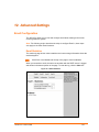
Email Configuration...................................................................................................110
Email Statistics _________________________________________________ 110
Email Configuration _____________________________________________ 111
Command Line Interface Settings ............................................................................113
Command Line Interface Statistics _________________________________ 113
CLI Configuration _______________________________________________ 114
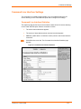
XML Configuration ....................................................................................................115
XML: Export Configuration ________________________________________ 115
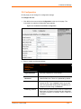
XML: Export Status _____________________________________________ 118
XML: Import System Configuration Page_____________________________ 119
13. Point to Point Protocol PPP
125
14. Tunneling
127
Connect Mode...........................................................................................................127
Accept Mode .............................................................................................................129
Disconnect Mode ......................................................................................................129
Packing Mode ...........................................................................................................130
Modem Emulation .....................................................................................................130
Command Mode ________________________________________________ 130
Serial Line Settings ...................................................................................................132
Statistics....................................................................................................................132
15. VIP
133
Tunneling with VIP Access .......................................................................................133
Obtaining a bootstrap file _________________________________________ 133
Importing the bootstrap file________________________________________ 134
XPort Pro™ User Guide
6
Contents
Enabling VIP___________________________________________________ 134
Configuring Tunnels to Use VIP ____________________________________ 134
16. Security in Detail
135
Secure Shell: SSH ....................................................................................................135
SSH Server Configuration ________________________________________ 135
SSH Client Configuration _________________________________________ 136
Secure Sockets Layer (SSL) ....................................................................................137
CipherSuites ___________________________________________________ 137
Certificates ____________________________________________________ 137
Utilities _______________________________________________________ 139
17. Branding the XPort Pro
141
Web Manager Customization ...................................................................................141
Command Mode .......................................................................................................142
18. Updating Firmware
143
Obtaining Firmware...................................................................................................143
Loading New Firmware .............................................................................................143
A: Technical Support
144
B: Binary to Hexadecimal Conversions
145
Converting Binary to Hexadecimal ...........................................................................145
Conversion Table _______________________________________________ 145
Scientific Calculator _____________________________________________ 146
C: Compliance
147
D: Warranty
149
Index
150
Figures
Figure 2-1. Sample Hardware Address ................................................................................................17
Figure 2-2. Product Label .....................................................................................................................18
Figure 4-1. Web Manager Home Page.................................................................................................23
Figure 4-2. Components of the Web Manager Page ............................................................................24
Figure 4-3. Device Status .....................................................................................................................27
Figure 5-1. Network 1 (eth0) Interface Status.......................................................................................28
Figure 5-2. Network 1 (eth0) Interface Configuration ...........................................................................29
Figure 5-3. Network 1 Ethernet Link .....................................................................................................32
Figure 6-1. Line 1 Statistics ..................................................................................................................33
Figure 6-2. Line 1 Configuration ...........................................................................................................34
Figure 6-3. Line 1 Command Mode ......................................................................................................36
Figure 6-4. Tunnel 1..............................................................................................................................38
Figure 6-5. Tunnel 1 Serial Settings .....................................................................................................39
XPort Pro™ User Guide
7
Contents
Figure 6-6a. Tunnel 1 Packing Mode (Mode = Disable) .......................................................................40
Figure 6-7b. Tunnel 1 Packing Mode (Mode = Timeout) ......................................................................40
Figure 6-8c. Tunnel 1 Packing Mode (Mode = Send Character) ..........................................................41
Figure 6-9. Tunnel 1 Accept Mode .......................................................................................................42
Figure 6-10. Tunnel 1 Connect Mode ...................................................................................................44
Figure 6-11. Host 2 Expanded ..............................................................................................................47
Figure 6-12. Host 1, Host 2 Exchanged................................................................................................48
Figure 6-13. Tunnel 1 Disconnect Mode...............................................................................................49
Figure 6-14. Tunnel 1 Modem Emulation .............................................................................................50
Figure 6-15. Terminal on Line 1 Configuration .....................................................................................51
Figure 6-16. Terminal on Network Configuration..................................................................................53
Figure 6-17. Host Configuration............................................................................................................54
Figure 7-1. CPM: CPs ...........................................................................................................................55
Figure 7-2. CPM: Groups......................................................................................................................58
Figure 8-1. DNS Settings ......................................................................................................................61
Figure 8-2. PPP Configuration Settings ................................................................................................62
Figure 8-3. SNMP Configuration...........................................................................................................64
Figure 8-4. FTP Configuration ..............................................................................................................65
Figure 8-5. TFTP Configuration ............................................................................................................66
Figure 8-6. Syslog .................................................................................................................................67
Figure 8-7. HTTP Statistics...................................................................................................................68
Figure 8-8. HTTP Configuration............................................................................................................69
Figure 8-9. HTTP Authentication ..........................................................................................................71
Figure 8-10. RSS ..................................................................................................................................73
Figure 8-11. LPD Statistics ...................................................................................................................74
Figure 8-12. LPD Configuration ............................................................................................................75
Figure 9-1. SSH Server: Host Keys ......................................................................................................77
Figure 9-2. SSH Server: Authorized Users...........................................................................................79
Figure 9-3. SSH Client: Known Hosts...................................................................................................80
Figure 9-4. SSH Client: Users...............................................................................................................82
Figure 9-5. SSL .....................................................................................................................................84
Figure 10-1. VIP Statistics Page ...........................................................................................................87
Figure 10-2. VIP Configuration Page ....................................................................................................89
Figure 11-1. File system Statistics ........................................................................................................90
Figure 11-2. File system Browser .........................................................................................................92
Figure 11-3. TCP Protocol Page...........................................................................................................94
Figure 11-4. IP Protocol Page...............................................................................................................95
Figure 11-5. ICMP Protocol Page .........................................................................................................96
Figure 11-6. ARP Protocol Page ..........................................................................................................96
Figure 11-7. IP Address Filter Configuration ........................................................................................97
Figure 11-8. Query Port Configuration..................................................................................................98
Figure 11-9. Diagnostics: Hardware .....................................................................................................99
Figure 11-10. MIB-II Network Statistics ..............................................................................................100
Figure 11-11. IP Sockets ....................................................................................................................101
Figure 11-12. Diagnostics: Ping..........................................................................................................102
Figure 11-13. Diagnostics: Traceroute ...............................................................................................103
Figure 11-14. Diagnostics: DNS Lookup ............................................................................................104
Figure 11-15. Diagnostics: Memory....................................................................................................105
Figure 11-16. Diagnostics: Buffer Pools .............................................................................................106
Figure 11-17. Diagnostics: Processes ................................................................................................107
Figure 11-18. System..........................................................................................................................108
Figure 12-1. Email Statistics ...............................................................................................................110
Figure 12-2. Email Configuration ........................................................................................................111
Figure 12-3. Command Line Interface Statistics.................................................................................113
Figure 12-4. Command Line Interface Configuration .........................................................................114
Figure 12-5. XML: Export Configuration .............................................................................................116
XPort Pro™ User Guide
8
Contents
Figure 12-6. XML Status Record: Export Status.................................................................................118
Figure 12-7. XML: Import Configuration .............................................................................................120
Figure 12-8. XML: Import Configuration from External File ................................................................120
Figure 12-9. XML: Import from Filesystem .........................................................................................121
Figure 12-10. XML: Import Line(s) from Single Line Settings on the Filesystem ...............................123
XPort Pro™ User Guide
9
1. Using This Guide
Purpose and Audience
This guide provides the information needed to configure, use, and update the XPort
Pro™. It is intended for software developers and system integrators who are
embedding the XPort Pro in their designs.
Note: This guide occasionally refers to the XPort Pro as just the XPort.
Summary of Chapters
The remaining chapters in this guide include:
Chapter
Description
2: Introduction
Main features of the product and the protocols
it supports. Includes technical specifications.
3: Using DeviceInstaller
Instructions for viewing the current
configuration using DeviceInstaller.
4: Configuration Using Web
Manager
Instructions for accessing Web Manager and
using it to configure settings for the XPort Pro.
5: Network Settings
Instructions for using the web interface to
configure Ethernet settings.
6: Line, Tunnel, Terminal, and
Host Settings
Instructions for using the web interface to
configure line, tunnel, terminal, and host
settings.
7: Configurable Pin Manager
Information about the Configurable Pin
Manager (CPM) and how to set the
configurable pins to work with a device.
8: Services Settings
Instructions for using the web interface to
configure settings for DNS, SNMP, FTP, and
other services.
9: Security Settings
Instructions for using the web interface to
configure SSH and SSL security settings.
10: VIP Settings
Instructions for configuring a Virtual IP.
XPort Pro™ User Guide
10
1 Using This Guide
Chapter
Description
11: Maintenance and
Diagnostics Settings
Instructions for using the web interface to
maintain the XPort Pro, view statistics, files,
and logs, and diagnose problems.
12: Advanced Settings
Instructions for using the web interface to
configure email, CLI, and XML settings.
13: Point to Point Protocol
(PPP)
Description of PPP on the XPort Pro.
14: Tunneling
Information about tunneling features available
on the serial lines.
15: VIP
Information about Virtual IP (VIP) features
available on the XPort Pro.
16: Security in Detail
Description and configuration of SSH and SSL
security settings.
17: Branding the XPort Pro
Instructions for customizing the XPort Pro.
18: Updating Firmware
Instructions for obtaining the latest firmware
and updating the XPort Pro.
A: Technical Support
Instructions for contacting Lantronix Technical
Support.
B: Binary to Hexadecimal
Conversions
Instructions for converting binary values to
hexadecimals.
C: Compliance
Lantronix compliance information.
D: Warranty
Lantronix warranty statement.
XPort Pro™ User Guide
11
1 Using This Guide
Additional Documentation
The following documents are available on the product CD or the Lantronix Web site
(www.lantronix.com):
Document
Description
XPort Pro Integration Guide
Information about the XPort Pro hardware,
testing the XPort Pro using the demonstration
board, and integrating the XPort Pro into your
product.
XPort Pro Command
Reference
Instructions for accessing Command Mode (the
command line interface) using a Telnet
connection or through the serial port. Detailed
information about the commands. Also provides
details for XML configuration and status.
XPort Universal Demo
Board Quick Start
Instructions for getting the XPort Pro
demonstration board up and running.
Provides information needed to use the XPort
on the demo board.
XPort Universal Demo
Board User Guide
DeviceInstaller Online Help
Instructions for using the Lantronix Windowsbased utility to locate the XPort Pro and to view
its current settings.
Com Port Redirector Quick
Start and Online Help
Instructions for using the Lantronix Windowsbased utility to create virtual com ports.
Secure Com Port Redirector
User Guide
Instructions for using the Lantronix Windowsbased utility to create secure virtual com ports.
XPort Pro™ User Guide
12
2. Introduction
The XPort Pro embedded Ethernet Device Server is a complete network-enabling
solution in a 13.50 (0.531) X 16.25 (0.640) X 33.90 (1.335) package. This miniature
device server empowers original equipment manufacturers (OEMs) to go to market
quickly and easily with Ethernet networking and web page serving capabilities built
into their products. [DIMS = mm (in.)]
Key Features
Power Supply: Regulated 3.3V input required. There is a step-down converter to
1.5 volts for the processor core. All voltages have LC filtering to minimize noises
and emissions.
Controller: A Lantronix DSTni-FX 32-bit microprocessor, running at 166 MHz
internal bus and 83 MHz external bus.
Memory: 16 MB Flash and 8 MB SDRAM. Please contact your sales
representative if you need larger memory sizes.
Ethernet: 10/100 Mbps Ethernet transceiver
Serial Ports: One full, RS232-supporting high-speed serial port with all hardware
handshaking signals. Baud rate is software selectable (300 bps to 921600 bps).
Note: The standard baud rate of 460800 bps is not supported.
Configurable IO Pins (CPs): Up to three pins are configurable as general purpose
I/Os if no DTR or DCD is used on serial ports. Not 5V tolerant.
Interface Signals: 3.3V-level interface signals.
Temperature Range: Operates over an extended temperature range of -40°C to
+85°C.
Applications
The XPort Pro device server connects serial devices such as those listed below to
Ethernet networks using the IP protocol family.
ATM machines
CNC controllers
Data collection devices
XPort Pro™ User Guide
13
2 Introduction
Universal Power Supply (UPS) management unit
Telecommunications equipment
Data display devices
Security alarms and access control devices
Handheld instruments
Modems
Time/attendance clocks and terminals
Protocol Support
The XPort Pro device server contains a full-featured TCP/IP stack. Supported
protocols include:
ARP, IP, UDP, TCP, ICMP, BOOTP, DHCP, Auto IP, Telnet, DNS, FTP, TFTP,
HTTP(S), SSH, SSL/TLS, SNMP, SMTP, RSS, PPP and Syslog for network
communications and management.
TCP, UDP, TCP/AES, UDP/AES, Telnet, SSH and SSL/TLS for tunneling to the
serial port.
TFTP, FTP, and HTTP for firmware upgrades and uploading files.
Evolution OS™
XPort Pro incorporates The Lantronix Evolution OS™. Key features of the Evolution
OS™ include:
Built-in Web server for configuration and troubleshooting from Web-based
browsers
CLI configurability
SNMP management
XML data transport and configurability
Really Simple Syndication (RSS) information feeds
Enterprise-grade security with SSL and SSH
Comprehensive troubleshooting tools
XPort Pro™ User Guide
14
2 Introduction
Additional Features
Modem Emulation
In modem emulation mode, the XPort Pro can replace dial-up modems. The unit
accepts modem AT commands on the serial port, and then establishes a network
connection to the end device, leveraging network connections and bandwidth to
eliminate dedicated modems and phone lines.
Web-Based Configuration and Troubleshooting
Built upon Internet-based standards, the XPort Pro enables you to configure,
manage, and troubleshoot through a browser-based interface accessible anytime
from anywhere. All configuration and troubleshooting options are launched from a
web interface. You can access all functions via a Web browser, for remote access.
As a result, you decrease downtime (using the troubleshooting tools) and implement
configuration changes (using the configuration tools).
Command-Line Interface (CLI)
Making the edge-to-enterprise vision a reality, the XPort Pro with the Evolution OS™
uses industry-standard tools for configuration, communication, and control. For
example, the Evolution OS™ uses a Command Line Interface (CLI) whose syntax is
very similar to that used by data center equipment such as routers and hubs.
VIP Access
Virtual IP Access is the Lantronix technology that solves the access-through-firewall
problem. With VIP Access, the XPort Pro can act as a ManageLinx DSC and provide
direct access to your equipment behind a firewall.
SNMP Management
The XPort Pro supports full SNMP management, making it ideal for applications
where device management and monitoring are critical. These features allow networks
with SNMP capabilities to correctly diagnose and monitor XPort Pro.
XML-Based Architecture and Device Control
XML is a fundamental building block for the future growth of M2M networks. The
XPort Pro supports XML-based configuration setup records that make device
configuration transparent to users and administrators. The XML is easily editable with
a standard text or XML editor.
Really Simple Syndication (RSS)
The XPort Pro supports Really Simple Syndication (RSS), a rapidly emerging
technology for streaming and managing on-line content. RSS feeds all the
configuration changes that occur on the device. An RSS aggregator then reads
(polls) the feed. More powerful than simple email alerts, RSS uses XML as an
underlying Web page transport and adds intelligence to the networked device, while
not taxing already overloaded email systems.
XPort Pro™ User Guide
15
2 Introduction
Enterprise-Grade Security
Evolution OS™ provides the XPort Pro the highest level of networking security
possible. This ‘data center grade’ protection ensures that each device on the M2M
network carries the same level of security as traditional IT networking equipment in
the corporate data center.
By protecting the privacy of serial data transmitted across public networks, users can
maintain their existing investment in serial technology, while taking advantage of the
highest data-protection levels possible.
SSH and SSL can:
Verify the data received came from the proper source
Validate that the data transferred from the source over the network has not
changed when it arrives at its destination (shared secret and hashing)
Encrypt data to protect it from prying eyes and nefarious individuals
Provide the ability to run popular M2M protocols over a secure SSH or SSL
connection
In addition to keeping data safe and accessible, the XPort Pro has robust defenses to
hostile Internet attacks such as denial of service (DoS), which can be used to take
down the network. Moreover, the XPort Pro cannot be used to bring down other
devices on the network.
You can use the XPort Pro with the Lantronix Secure Com Port Redirector (SCPR) to
encrypt COM port-based communications between PCs and virtually any electronic
device. SCPR is a Windows application that creates a secure communications path
over a network between the computer and serial-based devices that are traditionally
controlled via a COM port. With SCPR installed at each computer, computers that
were formerly “hard-wired” by serial cabling for security purposes or to accommodate
applications that only understood serial data can instead communicate over an
Ethernet network or the Internet.
Terminal Server/Device Management
Remote offices can have routers, PBXs, servers and other networking equipment that
require remote management from the corporate facility. The XPort Pro easily
attaches to the serial ports on a server, Private Branch Exchange (PBX), or other
networking equipment to deliver central, remote monitoring and management
capability.
Troubleshooting Capabilities
The XPort Pro offers a comprehensive diagnostic toolset that lets you troubleshoot
problems quickly and easily. Available from the Web Manager, CLI, and XML
interfaces, the diagnostic tools let you:
View critical hardware, memory, MIB-II, buffer pool, and IP socket information.
Perform ping and traceroute operations.
Conduct forward or backup DNS lookup operations.
XPort Pro™ User Guide
16
2 Introduction
View all processes currently running on the XPort Pro, including CPU utilization
and total stack space available.
Configuration Methods
After installation, the XPort Pro requires configuration. For the unit to operate
correctly on a network, it must have a unique IP address on the network. There are
four basic methods for logging into the XPort Pro and assigning IP addresses and
other configurable settings:
DeviceInstaller: Configure the IP address and related settings and view current
settings on the XPort Pro using a Graphical User Interface (GUI) on a PC attached to
a network. (See page 19.)
Web Manager: Through a web browser, configure the XPort Pro settings using the
Lantronix Web Manager. (See page 22.)
Command Mode: There are two methods for accessing Command Mode(CLI):
making a Telnet connection or connecting a terminal (or a PC running a terminal
emulation program) to the unit’s serial port. (See the XPort Pro Command Reference
Guide for instructions and available commands.)
XML: The XPort Pro supports XML-based configuration and setup records that make
device configuration transparent to users and administrators. XML is easily editable
with a standard text or XML editor. (See the XPort Pro Command Reference Guide
for instructions and commands.)
Addresses and Port Numbers
Hardware Address
The hardware address is also referred to as the Ethernet address or MAC address.
The first three bytes of the Ethernet address are fixed and read 00-20-4A, identifying
the unit as a Lantronix product. The fourth, fifth, and sixth bytes are unique numbers
assigned to each unit.
Figure 2-1. Sample Hardware Address
00-20-4A-14-01-18
or
00:20:4A:14:01:18
IP Address
Every device connected to an IP network must have a unique IP address. This
address references the specific unit.
XPort Pro™ User Guide
17
2 Introduction
Port Numbers
Every TCP connection and every UDP datagram is defined by a destination and
source IP address, and a destination and source port number. For example, a Telnet
server commonly uses port number 23.
The following is a list of the default server port numbers running on the XPort Pro:
TCP Port 22: SSH Server (Command Mode configuration)
TCP Port 23: Telnet Server (Command Mode configuration)
TCP Port 80: HTTP (Web Manager configuration)
TCP Port 443: HTTPS (Web Manager configuration)
UDP Port 161: SNMP
TCP Port 21: FTP
UDP Port 69: TFTP
UDP Port 30718: LDP (Lantronix Discovery Protocol) port
TCP/UDP Port 10001: Tunnel 1
Product Information Label
The product information label on the unit contains the following information about the
specific unit:
Bar code
Product ID (name)
Product Revision
Part number
Hardware Address (MAC Address)
Figure 2-2. Product Label
XPort Pro™ User Guide
18
3. Using DeviceInstaller
This chapter covers the steps for locating a XPort Pro unit and viewing its properties
and device details.
Note: For instructions on using DeviceInstaller to configure the IP address and
related settings or for more advanced features, see the Device Installer online Help.
Note: Auto IP generates a random IP address in the range of 169.254.0.1 to
169.254.255.254 if no BOOTP or DHCP server is found.
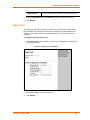
Accessing XPort Pro using DeviceInstaller
Note: Make note of the MAC address. It is needed to locate the XPort Pro using
DeviceInstaller.
Follow the instructions on the product CD to install and run DeviceInstaller.
1. Click Start
All Programs
Lantronix
DeviceInstaller
DeviceInstaller.
2. When DeviceInstaller starts, it will perform a network device search. To perform
another search, click the “Search” button.
3. Expand the XPort folder by clicking the + symbol next to the XPort folder icon.
The list of available Lantronix XPort Pro devices appears.
4. Select the XPort Pro unit by expanding its entry and clicking on its hardware
(MAC) address to view its configuration.
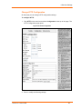
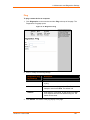
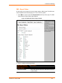
5. On the right page, click the Device Details tab. The current XPort Pro
configuration appears. This is only a subset of the full configuration; the full
configuration may be accessed via Web Manager, CLI, or XML.
XPort Pro™ User Guide
19
3 Using DeviceInstaller
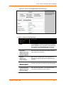
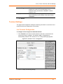
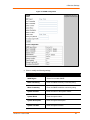
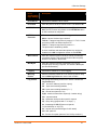
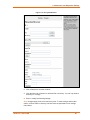
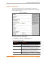
Device Details Summary
Note: The settings are Display Only in this table unless otherwise noted.
Current Settings
Description
Name
Name identifying the XPort Pro.
Group
Configurable field. Enter a group to categorize
the XPort Pro. Double-click the field, type in the
value, and press Enter to complete. This group
name is local to this PC and is not visible on
other PCs or laptops using DeviceInstaller.
Comments
Configurable field. Enter comments for the XPort
Pro. Double-click the field, type in the value, and
press Enter to complete. This description or
comment is local to this PC and is not visible on
other PCs or laptops using DeviceInstaller.
Device Family
Shows the XPort Pro device family type as
“XPort”.
Type
Shows the device type as “XPort Pro”.
ID
Shows the XPort Pro ID embedded within the
unit.
Hardware Address
Shows the XPort Pro hardware (MAC) address.
Firmware Version
Shows the firmware currently installed on the
XPort Pro.
Extended Firmware
Version
Provides additional information on the firmware
version.
Online Status
Shows the XPort Pro status as Online, Offline,
Unreachable (the XPort Pro is on a different
subnet), or Busy (the XPort Pro is currently
performing a task).
IP Address
Shows the XPort Pro current IP address. To
change the IP address, click the Assign IP button
on the DeviceInstaller menu bar.
XPort Pro™ User Guide
20
3 Using DeviceInstaller
Current Settings
Description
IP Address was Obtained
Appears “Dynamically” if the XPort Pro
automatically received an IP address (e.g., from
DHCP). Appears “Statically” if the IP address
was configured manually.
If the IP address was assigned dynamically, the
following fields appear:
Obtain via DHCP with values of True or False.
Obtain via BOOTP with values of True or False.
Subnet Mask
Shows the subnet mask specifying the network
segment on which the XPort Pro resides.
Gateway
Shows the IP address of the router of this
network.
There is no default.
Number of Ports
Shows the number of serial ports on this XPort
Pro.
Supports Configurable Pins
Shows True, indicating configurable pins are
available on the XPort Pro.
Supports Email Triggers
Shows True, indicating email triggers are
available on the XPort Pro.
Telnet Enabled
Indicates whether Telnet is enabled on this XPort
Pro.
Telnet Port
Shows the XPort Pro port for Telnet sessions.
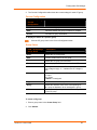
Web Enabled
Indicates whether Web Manager access is
enabled on this XPort Pro.
Web Port
Shows the XPort Pro port for Web Manager
configuration.
Firmware Upgradeable
XPort Pro™ User Guide
Shows True, indicating the XPort Pro firmware is
upgradeable as newer versions become
available.
21
4. Configuration Using Web Manager
This chapter describes how to configure the XPort Pro using Web Manager, the
Lantronix browser-based configuration tool. The unit’s configuration is stored in
nonvolatile memory and is retained without power. All changes take effect
immediately, unless otherwise noted.
Accessing Web Manager through a Web Browser
Note: You can also access the Web Manager by selecting the Web Configuration tab
on the DeviceInstaller window.
To access Web Manager:
1. Open a standard web browser (such as Netscape Navigator 6.x and above,
Internet Explorer 5.5. and above, Mozilla Suite, Mozilla Firefox, or Opera).
2. Enter the IP address of the XPort Pro in the address bar.
Note: The IP address may have been assigned manually using DeviceInstaller or
the serial port (see the XPort Pro Quick Start) or automatically by DHCP.
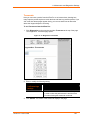
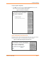
3. Enter your user name and password.
Note: The factory-default user name is “admin” and the factory-default password
is “PASS”.
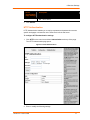
The Web Manager home page appears.
Note: The XPort Pro Status page (the home page) shows the overall XPort Pro
configuration and product information.
XPort Pro™ User Guide
22
4 Configuration Using Web Manager
Figure 4-1. Web Manager Home Page
XPort Pro™ User Guide
23
4 Configuration Using Web Manager
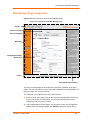
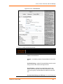
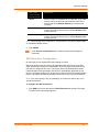
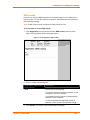
Web Manager Page Components
Figure 4-2 shows the areas of a typical Web Manager page.
Figure 4-2. Components of the Web Manager Page
Header
Items to configure
Links to subpages
Menu Bar
Configuration and/or
Status Area
Footer
Information and Help Area
The menu bar always appears at the left side of the page, regardless of the page
shown. The menu bar lists the names of the pages available in the Web Manager. To
bring up a page, click it in the menu bar.
The main area of the page has from one to three sections:
At the very top, many pages, such as the one in the example above, enable you
to link to sub pages. On some pages, you must also select the item you are
configuring, such as a line or a tunnel.
In the middle section of many pages, you can select or enter new configuration
settings. After you change settings, click Submit to apply the change. Some
XPort Pro™ User Guide
24
4 Configuration Using Web Manager
settings require you to reboot the XPort Pro before the settings take effect. Those
settings are identified in the appropriate sections in this chapter.
Note: Some pages show information such as statistics in this area rather than allow
you to enter settings.
Below the middle section of most pages shows the current configuration. In some
cases, you can take an action such as resetting or clearing a configurable.
The information or help area shows information or instructions associated with
the page.
The footer appears at the bottom of the page. It contains copyright information
and a link to the Lantronix home page.
Navigating the Web Manager
The Web Manager provides an intuitive point-and-click interface. A menu bar at the
left side of each page provides links you can click to navigate from one page to
another. Some pages are read-only, while others let you change configuration
settings.
Note: There may be times when you must reboot the XPort Pro for the new
configuration settings to take effect. The chapters that follow indicate when a change
requires a reboot.
Summary of Web Manager Pages
Web Manager
Page
Description
See
Page
Status
Shows product information and network, line, and
tunneling settings.
27
CLI
Shows Command Line Interface (CLI) statistics and lets
you change the current CLI configuration settings.
113
CPM
Shows information about the Configurable Pins Manager
(CPM) and how to set the configurable pins and pin
groups to work with a device.
55
Diagnostics
Lets you perform various diagnostic procedures.
99
DNS
Shows the current configuration of the DNS subsystem
and the DNS cache.
61
Email
Shows email statistics and lets you clear the email log,
configure email settings, and send an email.
110
Filesystem
Shows file system statistics and lets you browse the file
system to view a file, create a file or directory, upload files
using HTTP, copy a file, move a file, or perform TFTP
actions.
90
FTP
Shows statistics and lets you change the current
configuration for the File Transfer Protocol (FTP) server.
65
Host
Lets you view and change settings for a host on the
network.
54
XPort Pro™ User Guide
25
4 Configuration Using Web Manager
Web Manager
Page
Description
See
Page
HTTP
Shows HyperText Transfer Protocol (HTTP) statistics and
lets you change the current configuration and
authentication settings.
68
IP Address
Filter
Lets you specify all the IP addresses and subnets that are
allowed to send data to this device.
97
Line
Shows statistics and lets you change the current
configuration and Command mode settings of a serial
line.
33
LPD
Shows LPD (Line Printer Daemon) Queue statistics and
lets you configure the LPD and print a test page.
74
Network
Shows status and lets you configure the network
interface.
28
PPP
Lets you configure a network link using Point-to-Point
Protocol (PPP) over a serial line.
61
Protocol
Stack
Lets you perform lower level network stack-specific
activities.
94
Query Port
Lets you change configuration settings for the query port.
98
RSS
Lets you change current Really Simple Syndication (RSS)
settings.
73
SNMP
Lets you change the current Simple Network
Management Protocol (SNMP) configuration settings.
63
SSH
Lets you change the configuration settings for SSH server
host keys, SSH server authorized users, SSH client
known hosts, and SSH client users.
SSL
Lets you upload an existing certificate or create a new
self-signed certificate.
83
Syslog
Lets you specify the severity of events to log and the
server and ports to which the syslog should be sent.
67
System
Lets you reboot the XPort Pro, restore factory defaults,
upload new firmware, and change the XPort Pro long and
short names.
108
Terminal
Lets you change current settings for a terminal.
51
TFTP
Shows statistics and lets you change the current
configuration for the Trivial File Transfer Protocol (TFTP)
server.
66
Tunnel
Lets you change the current configuration settings for a
tunnel.
37
VIP
Lets you configure Virtual IP addresses to be used in
Tunnel Accept Mode and Tunnel Connect Mode.
87
XML
Lets you export XML configuration and status records,
and import XML configuration records.
115
XPort Pro™ User Guide
77
26
4 Configuration Using Web Manager
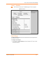
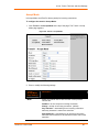
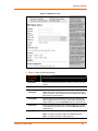
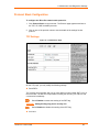
Device Status Page
The Device Status page is the first page that appears when you log into the Web
Manager. It also appears when you click the Status link in the menu bar. This readonly page shows XPort Pro product information, network settings, line settings, and
tunneling settings.
Figure 4-3. Device Status
XPort Pro™ User Guide
27
5. Network Settings
The Network Settings pages show the status of Ethernet link and let you configure it
on the device.
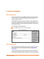
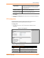
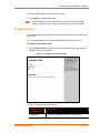
Network Settings
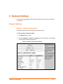
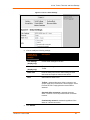
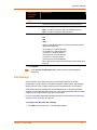
Network 1 (eth0) Interface Status
This page shows the status of the Ethernet network interface.
To view the network interface status:
1. Click Network on the menu.
2. Then click Network 1, Interface, and Status at the top of the page. The Network
1 (eth0) Interface Status page appears.
Figure 5-1. Network 1 (eth0) Interface Status
XPort Pro™ User Guide
28
5 Network Settings
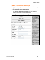
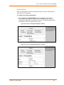
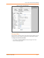
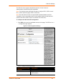
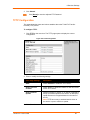
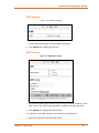
Network 1 (eth0) Interface Configuration
This page shows the configuration settings for the Ethernet connection and lets you
change these settings.
To view and configure network interface settings:
1. Click Network 1, Interface, and Configuration at the top of the page. The
Network 1 (eth0) Interface Configuration page appears.
Figure 5-2. Network 1 (eth0) Interface Configuration
XPort Pro™ User Guide
29
5 Network Settings
2. Enter or modify the following settings:
Network 1
Interface
Configuration
Page Settings
Description
BOOTP Client
Select On or Off. At boot up the XPort Pro will
attempt to obtain an IP address from a BOOTP
server.
Notes: Overrides the configured IP address, network
mask, gateway, hostname, and domain.
When DHCP is On, the system automatically uses
DHCP, regardless of whether BOOTP Client is On.
DHCP Client
Select On or Off. At boot up the XPort Pro will
attempt to lease an IP address from a DHCP server
and maintain the lease at regular intervals.
Note: Overrides BOOTP, the configured IP address,
network mask, gateway, hostname, and domain.
IP Address
Enter the XPort Pro static IP address.
You may enter it alone, in CIDR format, or with an
explicit mask.
The IP address consists of four octets separated by a
period and is used if BOOTP and DHCP are both set
to Off. Changing this value requires you to reboot the
XPort Pro.
Note: When DHCP is enabled, the XPort Pro tries to
obtain an IP address from DHCP. If it cannot, the
XPort Pro uses an Auto IP address in the range of
169.254.xxx.xxx.
Default Gateway
Enter the IP address of the router for this network. Or,
clear the field (appears as <None>). This address is
only used for static IP address configuration.
Hostname
Enter the XPort Pro hostname. It must begin with a
letter, continue with a sequence of letters, numbers,
and/or hyphens, and end with a letter or number.
Domain
Enter the XPort Pro's domain name.
DHCP Client ID
Enter the ID if the DHCP server uses a DHCP ID. The
DHCP server’s lease table shows IP addresses and
MAC addresses for devices. The lease table shows
the Client ID, in hexadecimal notation, instead of the
XPort Pro MAC address.
Primary DNS
IP address of the primary name server. This entry is
required if you choose to configure DNS (Domain
Name Server) servers.
XPort Pro™ User Guide
30
5 Network Settings
Network 1
Interface
Configuration
Page Settings
Description
Secondary DNS
IP address of the secondary name server.
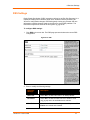
3. To save changes, click Submit. Some Changes to the following settings require
a reboot for the changes to take effect:
DHCP Client On/Off
BOOTP Client On/Off
IP address
Network mask
DHCP Client ID.
Note: If DHCP or BOOTP fails, AutoIP intervenes and assigns an address. In this
case, the static IP (if configured) is ignored.
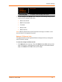
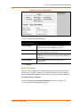
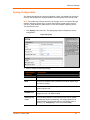
Network 1 Ethernet Link
This page shows the current negotiated Ethernet settings and lets you change the
speed and duplex settings.
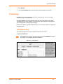
To view and configure the Ethernet link:
1. Click Network on the menu bar. Then click Network 1 and Link at the top of the
page. The Network 1 (eth0) Ethernet Link page appears. From another Network
page, click Network 1 and Link at the top of the page.
XPort Pro™ User Guide
31
5 Network Settings
Figure 5-3. Network 1 Ethernet Link
The Status table shows the current negotiated settings. The Configuration table
shows the current range of allowed settings.
2. Enter or modify the following settings:
Network 1-Ethernet
Link Page Settings
Description
Speed
Select the Ethernet link speed. (Default is Auto.)
Duplex
Select the Ethernet link duplex mode. (Default is Auto.)
3. Click Submit. The changes take effect immediately.
XPort Pro™ User Guide
32
6. Line, Tunnel, Terminal, and Host Settings
Line Settings
The Line Settings pages display the status and statistics for each of the serial lines
(ports). They also let you change the character format and Command Mode settings
for the serial lines.
Note: The following section describes the steps to view and configure Line 1
settings; these steps also apply to Line 2 menu options.
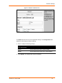
Line 1 Statistics
This read-only page shows the status and statistics for the serial line selected at the
top of this page.
Select Line on the menu bar. The Line 1 Statistics page appears.
Figure 6-1. Line 1 Statistics
XPort Pro™ User Guide
33
6 Line, Tunnel, Terminal, and Host Settings
Line 1 Configuration
This page shows the configuration settings for the serial line selected at the top of the
page and lets you change the settings for that serial line.
To configure Line 1:
1. Click Line 1 and Configuration at the top of the page. The Line 1 Configuration
page appears.
Figure 6-2. Line 1 Configuration
2. Enter or modify the following settings:
Line Configuration
Page Settings
Description
Name
Enter a name for the line. The default Name is blank.
Interface
Select the interface type from the drop-down menu. The
default is RS232.
State
Indicates whether the current line is enabled. To change the
status, select Enabled or Disabled from the drop-down
menu.
XPort Pro™ User Guide
34
6 Line, Tunnel, Terminal, and Host Settings
Line Configuration
Page Settings
Description
Protocol
Select the protocol from the drop-down menu. The default is
Tunnel.
Baud Rate
Select the baud rate from the drop-down menu. The default
is 9600.
Parity
Select the parity from the drop-down menu. The default is
None.
Data Bits
Select the number of data bits from the drop-down menu.
The default is 8.
Stop Bits
Select the number of stop bits from the drop-down menu.
The default is 1.
Flow Control
Select the flow control from the drop-down menu. The
default is None.
Xon Char
Specify the character to use to start the flow of data when
Flow Control is set to Software. Prefix a decimal character
with \ or a hexadecimal character with 0x, or provide a single
printable character. The default Xon char is 0x11.
Xoff Char
Specify the character to use to stop the flow of data when
Flow Control is set to Software. Prefix a decimal character
with \ or a hexadecimal character with 0x, or provide a single
printable character. The default Xoff char is 0x13.
Gap Timer
The driver forwards received serial bytes after the Gap
Timer delay from the last character received. By default, the
delay is four character periods at the current baud rate
(minimum 1 ms).
Threshold
The driver will also forward received characters after
Threshold bytes have been received.
3. Click Submit.
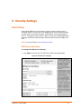
Line 1 Command Mode
Setting Command Mode enables the CLI on the serial line.
To configure Line 1 Command Mode:
1. Click Line 1 and Command Mode at the top of the page. The Line 1 Command
Mode page appears.
XPort Pro™ User Guide
35
6 Line, Tunnel, Terminal, and Host Settings
Figure 6-3. Line 1 Command Mode
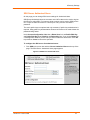
2. Enter or modify the following settings:
Line –
Command Mode
Page Settings
Description
Mode
Select the method of enabling Command Mode or choose to
disable Command Mode.
Always = immediately enables Command Mode for the serial
line.
Use Serial String = enables Command Mode when the serial
string is read on the serial line during boot time.
Use CP Group = enables Command Mode based on the
status of a CP Group. When the value matches the current
value of the group, Command Mode is enabled on the serial
line.
Use both Serial String and CP Group = the serial string and
XPort Pro™ User Guide
36
6 Line, Tunnel, Terminal, and Host Settings
Line –
Command Mode
Page Settings
Description
the value of the CP group must be matched to enable
Command Mode.
Disabled = turns off Command Mode.
Wait Time
Enter the wait time for the serial string during boot-up in
milliseconds.
Serial String
Enter the serial string characters. Select a string type.
Text = string of bytes that must be read on the Serial Line
during boot time to enable Command Mode. It may contain a
time element in x milliseconds, in the format {x}, to specify a
required delay.
Binary = string of characters representing byte values where
each hexadecimal byte value starts with \0x and each
decimal byte value starts with \.
Echo Serial
String
Select Yes to enable echoing of the serial string at boot-up.
CP Group
Enter the name and decimal value of the CP group.
Signon
Message
Enter the boot-up signon message. Select a string type.
Text = string of bytes sent on the serial line during boot time.
Binary = one or more byte values separated by commas.
Each byte value may be decimal or hexadecimal. Start
hexadecimal values with 0x.
Note: This string will be output on the serial port at boot,
regardless of whether command mode is enabled or not.
3. In the Current Configuration table, clear currently stored settings as necessary.
4. Click Submit.
Tunnel Settings
The Tunnel pages allow you to view current statistics and configure serial settings,
Connect Mode, Accept Mode, Disconnect Mode, Packing Mode, start and stop
characters, modem emulation, and AES keys.
Note: The following section describes the steps to view and configure Tunnel 1
settings; these steps also apply to Tunnel 2 menu options.
XPort Pro™ User Guide
37
6 Line, Tunnel, Terminal, and Host Settings
Tunnel 1 – Statistics
Click Tunnel on the menu bar. The Statistics page for Tunnel 1 appears.
Figure 6-4. Tunnel 1
Serial Settings
This page shows the settings for the tunnel selected at the top of the page and lets
you change the settings.
To configure serial settings:
1. Click Tunnel 1 and Serial Settings at the top of the page. The Tunnel 1 Serial
Settings page appears.
XPort Pro™ User Guide
38
6 Line, Tunnel, Terminal, and Host Settings
Figure 6-5. Tunnel 1 Serial Settings
2. View or modify the following settings:
Tunnel Serial
Settings Page
Settings
Description
Line Settings
Current serial settings for the line.
(display only)
Protocol
(display only)
The protocol being used on the line. In this case,
Tunnel.
Buffer Size
Enter the buffer size used for the tunneling of serial
data received. Requires reboot to take effect.
DTR
Select when to assert DTR.
TruPort = asserted whenever either a connect or an
accept mode tunnel connection is active with the Telnet
Protocol RFC2217 saying that the remote DSR is
asserted.
Asserted while connected = asserted whenever
either a connect or an accept mode tunnel connection
is active.
Continuously asserted = asserted regardless of the
status of a tunnel connection.
3. Click Submit.
XPort Pro™ User Guide
39
6 Line, Tunnel, Terminal, and Host Settings
Packing Mode
When in Packing Mode, data is not transferred one byte at a time. Instead, data is
queued and sent in segments.
To configure the tunnel Packing Mode:
1. Select Tunnel 1 and Packing Mode at the top of the page. The Tunnel 1
Packing Mode page appears. Depending on the Mode selection, different
configurable parameters are presented to the user. The following figures show
the display for each of the three packing modes.
Figure 6-6a. Tunnel 1 Packing Mode (Mode = Disable)
Figure 6-7b. Tunnel 1 Packing Mode (Mode = Timeout)
XPort Pro™ User Guide
40
6 Line, Tunnel, Terminal, and Host Settings
Figure 6-8c. Tunnel 1 Packing Mode (Mode = Send Character)
2. Enter or modify the following settings:
Tunnel - Packing
Mode Page
Settings
Description
Mode
Select Disable to disable Packing Mode completely.
Select Timeout to send data after the specified time
has elapsed. Select Send Character to send the
queued data when the send character is received.
Threshold
Send the queued data when the number of queued
bytes reaches the threshold.
(Appears for both
Timeout and Send
Character Modes)
Timeout
(Appears for
Timeout Mode)
Send Character
(Appears for Send
Character Mode)
Trailing Character
(Appears for Send
Character Mode)
Enter a time, in milliseconds, for the XPort Pro to
send the queued data after the first character was
received.
Enter the send character. Upon receiving this
character, the XPort Pro sends out the queued data.
Enter the trailing character. This character is sent
immediately following the send character.
3. Click Submit.
XPort Pro™ User Guide
41
6 Line, Tunnel, Terminal, and Host Settings
Accept Mode
In Accept Mode, the XPort Pro listens (waits) for incoming connections.
To configure the tunnel’s Accept Mode:
1. Click Tunnel 1 and Accept Mode at the top of the page. The Tunnel 1 Accept
Mode page appears.
Figure 6-9. Tunnel 1 Accept Mode
2. Enter or modify the following settings:
Tunnel Accept Mode
Page Settings
Description
Mode
Select the method used to start a tunnel in Accept mode.
Choices are:
Disabled = do not accept an incoming connection.
Always = accept an incoming connection. (default)
Any Character = start waiting for an incoming connection
when any character is read on the serial line.
Start Character = start waiting for an incoming connection
when the start character for the selected tunnel is read on the
serial line.
XPort Pro™ User Guide
42
6 Line, Tunnel, Terminal, and Host Settings
Tunnel Accept Mode
Page Settings
Description
Modem Control Asserted = start waiting for an incoming
connection as long as the Modem Control pin (DSR) is
asserted on the serial line until a connection is made.
Modem Emulation = start waiting for an incoming connection
when triggered by modem emulation AT commands. Connect
mode must also be set to Modem Emulation.
Local Port
Enter the port number for use as the local port. The defaults
are port 10001 for Tunnel 1 and port 10002 for Tunnel 2.
Protocol
Select the protocol type for use with Accept Mode. The default
protocol is TCP. If you select TCP AES you will need to
configure the AES keys.
TCP Keep
Alive
Enter the time, in seconds, the XPort Pro waits during a silent
connection before checking if the currently connected network
device is still on the network. If the unit then gets no response
after 8 attempts, it drops that connection.
Flush Serial
Data
Select Enabled to flush the serial data buffer on a new
connection.
Block Serial
Data
Select On to block, or not tunnel, serial data transmitted to the
XPort Pro.
Block Network
Data
Select On to block, or not tunnel, network data transmitted to
the XPort Pro.
Password
Enter a password that clients must send to the XPort Pro
within 30 seconds from opening a network connection to
enable data transmission.
The password can have up to 31 characters and must contain
only alphanumeric characters and punctuation. When set, the
password sent to the XPort Pro must be terminated with one of
the following: (a) 0x0A (LF), (b) 0x00, (c) 0x0D 0x0A (CR LF),
or (d) 0x0D 0x00.
Email on
Connect
Select whether the XPort Pro sends an email when a
connection is made. Select None if you do not want to send an
email. Otherwise, select the Email profile to use for sending.
Email on
Disconnect
Select whether the XPort Pro sends an email when a
connection is closed. Select None if you do not want to send
an email. Otherwise, select the Email profile to use for
sending.
CP Output
Identifies a CP or CP Group whose value should change when
a connection is established and dropped.
3. Click Submit.
XPort Pro™ User Guide
43
6 Line, Tunnel, Terminal, and Host Settings
Connect Mode
Connect mode defines how the unit makes an outgoing connection.
To configure Tunnel 1 Connect Mode:
1. Select Tunnel 1 and Connect Mode at the top of the page. The Tunnel 1
Connect Mode page appears.
Figure 6-10. Tunnel 1 Connect Mode
XPort Pro™ User Guide
44
6 Line, Tunnel, Terminal, and Host Settings
2. Enter or modify the following settings:
Tunnel –
Connect Mode
Page Settings
Description
Mode
Select the method to be used to attempt a connection to
a remote host or device. Choices are:
Always = a connection is attempted until one is made. If
the connection gets disconnected, the XPort Pro retries
until it makes a connection. (default)
Disable = an outgoing connection is never attempted.
Any Character = a connection is attempted when any
character is read on the serial line.
Start Character = a connection is attempted when the
start character for the selected tunnel is read on the
serial line.
Modem Control Asserted = a connection is attempted
as long as the Modem Control pin (DSR) is asserted,
until a connection is made.
Modem Emulation = a connection is attempted when
triggered by modem emulation AT commands.
Local Port
Enter the port for use as the local port. A random port is
selected by default. Once you have configured a
number, click the Random link in the Current
Configuration to switch back to random.
Host
Click <None> in the Host field to configure the Host
parameters.
VIP = Enabling the VIP directs the tunnel to connect to a
remote Lantronix Virtual IP identified by the VIP Name.
Default is Disabled.
VIP Name = Displays configured VIP name, used only if
VIP is enabled.
Address = Displays configured IP address or DNS
address, used only if VIP is disabled.
Port = Displays configured Port.
Protocol = Select the protocol type for use with Connect
Mode. The default protocol is TCP. If you select TCP
AES you will need to configure the AES keys.
SSH Username = Displays configured username, used
only if SSH protocol is selected.
TCP Keep Alive = Default is 45000 milliseconds.
AES Encrypt/Decrypt Key = Displays presence of key,
used only if protocol with AES is selected.
Reconnect Timer
XPort Pro™ User Guide
Enter the reconnect time in milliseconds. The XPort Pro
attempts to reconnect after this amount of time after
failing a connection or exiting an existing connection.
45
6 Line, Tunnel, Terminal, and Host Settings
Tunnel –
Connect Mode
Page Settings
Description
Flush Serial Data
Select whether to flush the serial line when a connection
is made. Choices are:
Enabled = flush the serial line when a connection is
made.
Disabled = do not flush the serial line. (default)
Block Serial Data
Select On to block (not tunnel) serial data transmitted to
the XPort Pro.
Block Network
Data
Select On to block (not tunnel) network data transmitted
to the XPort Pro.
Email on
Connect
Select whether the XPort Pro sends an email when a
connection is made. Select None if you do not want to
send an email. Otherwise, select the Email profile to use.
Email on
Disconnect
Select whether the XPort Pro sends an email when a
connection is closed. Select None if you do not want to
send an email. Otherwise, select the Email profile to use.
CP Output
Identifies a CP or CP Group whose value should change
when a connection is established and when it is
dropped.
3. Click Submit.
Host 1 is configured. A second host appears underneath Host 1 since the XPort Pro
supports configuration of up to sixteen hosts.
Connecting Multiple Hosts
If more than one Host is configured, a Host Mode option appears. Host Mode
controls how multiple hosts will be used in Connect Mode.
The following selections are available:
Sequential – When it is time for the tunnel to connect it will start with Host 1 and
attempt each host in sequence until a connection is accomplished. Default
selection.
Simultaneous – When it is time for the tunnel to connect it will connect to all of
the hosts that accept a connection.
Configuring Additional Hosts
The Host fields contain the information necessary to connect to the specified host.
To configure Host 2:
1. Click <None> in the Host 2 field. Host 2 expands.
XPort Pro™ User Guide
46
6 Line, Tunnel, Terminal, and Host Settings
2. Enter IP address in the Address field.
3. Click Submit.
Note: Repeat these steps to configure any subsequent hosts up to sixteen.
Figure 6-11. Host 2 Expanded
Host IP Promotion
The XPort Pro allows Host IP promotion of individual hosts in the overall sequence.
To promote a specific Host:
1. Click the arrow icon
in the desired Host field, for example Host 2.
2. The selected Host exchanges its place with the Host above it.
XPort Pro™ User Guide
47
6 Line, Tunnel, Terminal, and Host Settings
Figure 6-12. Host 1, Host 2 Exchanged
Disconnect Mode
Disconnect Mode is disabled by default. When enabled, Disconnect Mode runs in the
background of an active connection to determine when a disconnection is required.
To configure the tunnel Disconnect Mode:
1. Click Tunnel 1 and Disconnect Mode at the top of the page. The Tunnel 1
Disconnect Mode page appears.
XPort Pro™ User Guide
48
6 Line, Tunnel, Terminal, and Host Settings
Figure 6-13. Tunnel 1 Disconnect Mode
2. Enter or modify the following settings:
Tunnel – Disconnect
Mode Page Settings
Description
Stop Character
Enter the stop character in ASCII, hexadecimal, or
decimal notation. Select <None> to disable.
Modem Control
Select Enabled to disconnect when the modem control
pin is not asserted on the serial line.
Timeout
Enter a time, in milliseconds, for the XPort Pro to
disconnect on a timeout. The value 0 (zero) disables the
idle timeout.
Flush Serial Data
Select Enabled to flush the serial data buffer on a
disconnection.
3. Click Submit.
Modem Emulation
A tunnel in Connect Mode can be initiated using modem commands incoming from
the Serial Line. This page enables you to configure the modem emulation settings
when you select Modem Emulation as the Tunnel 1 or Tunnel 2 Connect Mode type.
To configure modem emulation:
1. Select Tunnel 1 and then Modem Emulation at the top of the page. The
Tunnel 1 Modem Emulation page appears.
XPort Pro™ User Guide
49
6 Line, Tunnel, Terminal, and Host Settings
Figure 6-14. Tunnel 1 Modem Emulation
2. Enter or modify the following settings:
Tunnel- Modem
Emulation Page
Settings
Description
Echo Pluses
Select On to echo +++ when entering modem
Command Mode.
Echo Commands
Select On to echo the modem commands to the
console.
Verbose Response
Select On to send modem response codes out on the
serial line.
Response Type
Select the type of response code: Text or Numeric.
Error Unknown
Commands
Select whether an ERROR or OK response is sent in
reply to unrecognized AT commands. Choices are:
Enabled = ERROR is returned for unrecognized AT
commands.
Disabled = OK is returned for unrecognized AT
commands. Default is Disabled.
Incoming Connection
XPort Pro™ User Guide
Select whether Incoming Connection requests will be
disabled, answered automatically, or answered
manually. Default is Disabled.
50
6 Line, Tunnel, Terminal, and Host Settings
Connect String
Enter the connect string. This modem initialization string
prepares the modem for communications. It is a
customized string sent with the “CONNECT” modem
response code.
Display Remote IP
Selects whether the incoming RING sent on the Serial
Line is followed by the IP address of the caller. Default
is Disabled.
3. Click Submit.
Terminal Settings
This page shows configuration settings for attaching a terminal on a serial line or the
network and lets you change them as necessary.
Line Terminal Configuration
To configure a line to support an attached terminal:
1. Click Terminal on the menu and then select the line that is connected to the
terminal you want to configure. The default is Line 1. Configuration is
automatically selected. The Terminal on Line 1 Configuration page appears.
Figure 6-15. Terminal on Line 1 Configuration
2. Enter or modify the following settings:
XPort Pro™ User Guide
51
6 Line, Tunnel, Terminal, and Host Settings
Terminal on Line
Configuration Page
Settings
Description
Terminal Type
Enter text to describe the type of terminal. The text will
be sent to a host via IAC.
Note: IAC means, “interpret as command.” It is a way
to send commands over the network such as send
break or start echoing.
Login Connect
Menu
Select the interface to display when the user logs in.
Choices are:
Enabled = shows the Login Connect Menu.
Disabled = shows the CLI
Exit Connect Menu
Select whether to display a choice for the user to exit
the Login Connect Menu and reach the CLI. Choices
are:
Enabled = a choice allows the user to exit to the CLI.
Disabled = there is no exit to the CLI.
Send Break
Enter a Send Break control character, e.g., <control>
Y, or blank to disable.
When the Send Break control character is received
from the network on its way to the serial line, it is not
sent to the line; instead, the line output is forced to be
inactive (the break condition).
Break Duration
Enter how long the break should last in milliseconds.
Echo
Applies only to Connect Mode Telnet connections, not
to Accept Mode. Only disable Echo if your terminal
echoes, in which case you will see double of each
character typed.
3. To save changes, click Submit.
Network Terminal Configuration
To configure menu features applicable to CLI access via the network:
1. Click Terminal on the menu and then click Network at the top of the page.
Configuration is automatically selected. The Terminal on Network Configuration
page appears.
XPort Pro™ User Guide
52
6 Line, Tunnel, Terminal, and Host Settings
Figure 6-16. Terminal on Network Configuration
2. Enter or modify the following settings:
Terminal on Line
Configuration Page
Settings
Description
Terminal Type
Enter text to describe the type of terminal. The text will
be sent to a host via IAC.
Note: IAC means, “interpret as command.” It is a way
to send commands over the network such as send
break or start echoing.
Login Connect Menu
Select the interface to display when the user logs in.
Choices are:
Enabled = shows the Login Connect Menu.
Disabled = shows the CLI
Exit Connect Menu
Select whether to display a choice for the user to exit
the Login Connect Menu and reach the CLI. Choices
are:
Enabled = a choice allows the user to exit to the CLI.
Disabled = there is no exit to the CLI.
Echo
Applies only to Connect Mode Telnet connections, not
to Accept Mode. Only disable Echo if your terminal
echoes, in which case you will see double of each
character typed.
3. To save changes, click Submit.
XPort Pro™ User Guide
53
6 Line, Tunnel, Terminal, and Host Settings
Host Configuration
This page shows current settings for a remote host and lets you change these
settings.
1. Click Host on the menu and then click the desired host at the top of the page.
Configuration is automatically selected. (Host 1 is the default.) Host Configuration
page appears.
Figure 6-17. Host Configuration
2. Enter or modify the following settings:
Host Page
Host Page
Settings
Description
Name
Enter a name for the host. This name appears on the Login
Connect Menu. To leave a host out of the menu, leave this field
blank.
Protocol
Select the protocol to use to connect to the host. Choices are:
Telnet
SSH
Note: SSH keys must be loaded or created on the SSH page for
the SSH protocol to work.
SSH
Username
Appears if you selected SSH as the protocol. Enter a username to
select a pre-configured Username/Password/Key (configured on
the SSH: Client Users page), or leave it blank to be prompted for
a username and password at connect time.
Remote
Address
Enter an IP address for the host to which the XPort will connect.
Remote
Port
Enter the port on the host to which the XPort will connect.
3. To save changes, click Submit.
XPort Pro™ User Guide
54
7. Configurable Pin Manager
The Configurable Pin Manager is responsible for assignment and control of the
configurable pins (CPs) available on the XPort Pro. There are three configurable pins
on the XPort Pro.
You can configure the CPs by making them part of a group. A CP Group may consist
of one or more CPs This increases flexibility when incorporating the XPort Pro into
another system.
CPM: Configurable Pins
Each CP is associated with an external hardware pin. CPs can trigger an outside
events, like sending an email message or starting Command Mode on a serial Line.
To configure the XPort Pro CPs:
1. Click CPM on the menu bar and then CPs at the top of the page. The CPM: CPs
page appears.
Figure 7-1. CPM: CPs
XPort Pro™ User Guide
55
7 Configurable Pin Manager
The Current Configuration table shows the current settings for each CP.
Current Configuration
CPM – CPs
Page Current
Configuration
Description
CP
Indicates the configurable pin number.
Pin #
Indicates the hardware pin number associated with the CP.
Configured As
Shows the CP configuration. A CP configured as Input is set
to read input. A CP configured as Output drives data out of
the XPort Pro.
Value
Indicates the current status of the CP:
1 = asserted.
0 = de-asserted.
Inv = the CP is inverted.
Groups
Indicates the number of groups in which the CP is a member.
Active In Group
A CP can be a member of several groups. However, it may
only be active in one group. This field shows the group in
which the CP is active.
2. To display the CP status of a specific pin, click the CP number in the Current
Configuration table. The CP Status table shows the information about the CP.
CPM – CPs Page CP
Status
Description
Name
Shows the CP number.
State
Shows the current enable state of the CP.
Type
Indicates whether the CP is set for input or output.
Value
Shows the last bit in the CP current value.
Bit
Visual display of the 32 bit placeholders for a CP.
Level
A “+” symbol indicates the CP is asserted (the voltage is
high). A “-“indicates the CP voltage is low.
I/O
Indicates the current status of the pin:
I = input
O = output
<blank> = unassigned
Logic
An “I” indicates the CP is inverted.
Binary
Shows the assertion value of the corresponding bit.
CP#
Shows the CP number.
Groups
Lists the groups in which the CP is a member.
Note: To modify a CP, all groups in which it is a member must be disabled.
XPort Pro™ User Guide
56
7 Configurable Pin Manager
To change a CP output value:
1. Select the CP from the drop-down list.
2. Enter the CP value.
3. Click Submit.
To change a CP configuration:
1. Select the CP from the drop-down list.
2. Select the CP configuration from the drop-down list.
3. (If necessary) Select the Assert Low checkbox.
4. Click Submit.
Note: These changes to a CP are not saved in FLASH. Instead, these CP settings
are used when the CP is added to a CP Group. When the CP Group is saved, its CP
settings are saved with it. Thus, a particular CP may be defined as “Input” in one
group but as “Output” in another. Only one group containing any particular CP may
be enabled at once.
XPort Pro™ User Guide
57
7 Configurable Pin Manager
CPM: Groups
The CP Groups page allows for the management of CP groups. Groups can be
created or deleted. CPs can be added to or removed from groups. A group, based on
its state, can trigger outside events (such as sending email messages). Only an
enabled group can be a trigger.
To configure the XPort Pro CP groups:
1. Click CPM on the menu bar and then Groups at the top of the page. The CPM:
Groups page appears.
Figure 7-2. CPM: Groups
XPort Pro™ User Guide
58
7 Configurable Pin Manager
2. The Current Configuration table shows the current settings for each CP group.
Current Configuration
CPM – Groups Page
Current
Configuration
Description
Group Name
Shows the CP group’s name.
State
Indicates whether the group is enabled or disabled.
CP Info
Provides CP group information.
To display the status of a specific group
Click the CP group name in the Current Configuration table.
Group Status
CPM – Groups Page
Group Status
Description
Name
Shows the CP Group name.
State
Current enable state of the CP group.
Value
Shows the CP group’s current value.
Bit
Visual display of the 7 bit placeholders for a CP.
Level
A “+” symbol indicates the CP’s bit position is asserted
(the voltage is high). A “-“ indicates the CP voltage is
low.
I/O
Indicates the current status of the pin:
I = input
O = output
<blank> = unassigned
Logic
An “I” indicates the CP output is inverted.
Binary
Shows the assertion value of the corresponding bit.
X = group is disabled or bit is unassigned in group
CP#
Shows the configurable pin number and its bit position
in the CP group.
To create a CP group:
1. Enter a group name in the Create Group field.
2. Click Submit.
XPort Pro™ User Guide
59
7 Configurable Pin Manager
To delete a CP group:
1. Select the CP group from the Delete Group drop-down list.
2. Click Submit.
To enable or disable a CP group:
1. Select the CP group from the Set drop-down list.
2. Select the state (Enabled or Disabled) from the drop-down list.
3. Click Submit.
To set a CP group’s value:
1. Select the CP group from the Set drop-down list.
2. Enter the CP group’s value in the value field.
3. Click Submit.
To add a CP to a CP group:
1. Select the CP from the Add drop-down list.
2. Select the CP group from the drop-down list.
3. Select the CP bit location from the bit drop-down list.
4. Click Submit.
To delete a CP from a CP group:
1. Select the CP from the Remove drop-down list.
2. Select the CP group from the drop-down list.
3. Click Submit.
XPort Pro™ User Guide
60
8. Services Settings
DNS Configuration
This page shows the active run-time settings for the domain name system (DNS)
protocol. The primary and secondary DNS addresses come from the active interface.
The static addresses from the Network Interface Configuration page may be
overridden by DHCP or BOOTP.
The DNS page also shows any contents in the DNS cache. When a DNS name is
resolved using a forward lookup, the results are stored in the DNS cache temporarily.
The XPort Pro consults this cache when performing forward lookups. Each item in
the cache eventually times out and is removed automatically after a certain period, or
you can delete it manually.
To view the XPort Pro DNS configuration:
Click DNS on the menu bar. The DNS page appears.
Figure 8-1. DNS Settings
PPP Configuration
Point-to-Point Protocol (PPP) establishes a direct connection between two nodes. It
defines a method for data link connectivity between devices using physical layers
(such as serial lines). For more information about PPP, see 13 Point to Point
Protocol PPP.
The XPort Pro supports two types of PPP authentication: Password Authentication
Protocol (PAP) and Challenge Handshake Authentication Protocol (CHAP). Both of
these authentication methods require the configuration of a username and password.
XPort Pro™ User Guide
61
8 Services Settings
The XPort Pro also supports authentication scheme of “None” when no
authentication is required during link negotiation.
Note: The following section describes the steps to configure PPP 1 (PPP on serial
line 1); these steps also apply to PPP on other lines.
Note: Since the XPort Pro does not support NAPT (Network Address and Port
Translation), static routing table entries must be added to both the serial-side and
network-side devices (both of which are external to the XPort Pro).
To configure the XPort Pro PPP configuration:
1. Click PPP on the menu bar and Line1 at the top of the page. The PPP on Line 1
– Configuration page appears.
Figure 8-2. PPP Configuration Settings
2. Enter or modify the following settings:
PPP Configuration Page
Settings
Description
Local IP Address
Enter the IP address assigned to the XPort Pro’s
PPP interface.
XPort Pro™ User Guide
62
8 Services Settings
PPP Configuration Page
Settings
Description
Peer IP Address
Enter the IP address assigned to the peer (when
requested during negotiation).
Authentication Mode
Choose the authentication mode:
None = no authentication is required.
PAP = Password Authentication Protocol.
CHAP = Challenge Handshake Authentication
Protocol.
3. Click Submit.
SNMP Configuration
This page is used to configure the Simple Network Management Protocol (SNMP)
agent. Using this page, you can configure the SNMP service to send a trap when it
receives a request for information that contains an incorrect community name and
does not match an accepted system name for the service.
To configure SNMP:
1. Click SNMP on the menu bar. The SNMP page opens and shows the current
SNMP configuration.
XPort Pro™ User Guide
63
8 Services Settings
Figure 8-3. SNMP Configuration
2. Enter or modify the following settings:
SNMP Page Settings
Description
SNMP Agent
Select On to enable SNMP.
Read Community
Enter the SNMP read-only community string.
Write Community
Enter the SNMP read/write community string.
System Contact
Enter the name of the system contact.
System Name
Enter the system name.
System Description
Enter the system description.
System Location
Enter the system location.
XPort Pro™ User Guide
64
8 Services Settings
Traps Enabled
Select On to enable the transmission of the SNMP
cold start trap messages. This trap is generated
during system boot.
Primary Trap Dest IP
Enter the primary SNMP trap host.
Secondary Trap Dest IP
Enter the secondary SNMP trap host.
3. Click Submit.
4. In the Current Configuration table, delete and clear currently stored settings as
necessary.
FTP Configuration
This page shows the current File Transfer Protocol (FTP) configuration and
connection status and various statistics about the FTP server.
To configure FTP:
1. Click FTP on the menu bar. The FTP page opens to display the current
configuration.
Figure 8-4. FTP Configuration
2. Enter or modify the following settings:
FTP Page Settings
Description
State
Select Enabled to enable the FTP server.
Admin Username
Enter the username to use when logging in via FTP.
Admin Password
Enter the password to use when logging in via FTP.
XPort Pro™ User Guide
65
8 Services Settings
3. Click Submit.
Click [Reset] to reset the adjacent FTP Password.
TFTP Configuration
This page shows the status and various statistics about the Trivial File Transfer
Protocol (TFTP) server.
To configure TFTP:
1. Click TFTP on the menu bar. The TFTP page opens to display the current
configuration.
Figure 8-5. TFTP Configuration
2. Enter or modify the following settings:
TFTP Page Settings
Description
State
Select Enabled to enable the TFTP server.
Allow TFTP File
Creation
Select whether to allow the creation of new files stored
on the TFTP server.
Allow Firmware
Update
Specifies whether or not the TFTP Server is allowed to
accept a firmware update for the device. An attempt to
update firmware is recognized based on the name of
the file.
Note: TFTP has no way to authenticate the client so
the device is open to malicious update.
3. Click Submit.
XPort Pro™ User Guide
66
8 Services Settings
Syslog Configuration
The Syslog page shows the current configuration, status, and statistics of the syslog.
Here you can configure the syslog destination and the severity of the events to log.
Note: The system log is always saved to local storage, but it is not retained through
reboots. Saving the system log to a server that supports remote logging services
(see RFC 3164) allows the administrator to save the complete system log history.
The default port is 514.
1. Click Syslog on the menu bar. The Syslog page opens to display the current
configuration.
Figure 8-6. Syslog
2. Enter or modify the following settings:
Syslog Page
Settings
Description
State
Select to enable or disable the syslog.
Host
Enter the IP address of the remote server to which system logs
are sent for storage.
Local Port
Enter the number of the local port on the XPort Pro from which
system logs are sent.
Remote Port
Enter the number of the port on the remote server that supports
logging services. The default is 514.
Severity Log
Level
From the drop-down box, select the minimum level of system
message the XPort Pro should log. This setting applies to all
syslog facilities. The drop-down list is in descending order of
severity (e.g., Emergency is more severe than Alert.)
XPort Pro™ User Guide
67
8 Services Settings
HTTP Configuration
Hypertext Transfer Protocol (HTTP) is the transport protocol for communicating
hypertext documents on the Internet. HTTP defines how messages are formatted and
transmitted. It also defines the actions web servers and browsers should take in
response to different commands. This page has three links at the top for viewing
statistics and for viewing and changing configuration and authentication settings.
HTTP Statistics
Note: The HTTP log is a scrolling log, with the last Max Log Entries cached and
viewable. You can change the maximum number of entries that can be viewed on the
HTTP Configuration Page.
To view HTTP statistics:
This page shows various statistics about the Hypertext Transfer Protocol (HTTP)
server.
Click HTTP on the menu bar and then Statistics at the top of the page. The
HTTP Statistics page appears.
Figure 8-7. HTTP Statistics
XPort Pro™ User Guide
68
8 Services Settings
Change HTTP Configuration
On this page you can change HTTP configuration settings.
To configure HTTP:
1. Click HTTP on the menu bar and then Configuration at the top of the page. The
HTTP Configuration page opens.
Figure 8-8. HTTP Configuration
2. Enter or modify the following settings:
XPort Pro™ User Guide
69
8 Services Settings
HTTP
Configuration
Page Settings
Description
HTTP Server
Select On to enable the HTTP server.
HTTP Port
Enter the port for the HTTP server to use. The default is 80.
HTTPS Port
Enter the port for the HTTPS server to use. The default is
443. The HTTP server only listens on the HTTPS Port when
an SSL certificate is configured.
HTTPS
Protocols
Select to enable or disable the following protocols:
SSL3 = Secure Sockets Layer version 3
TLS1.0 = Transport Layer Security version 1.0. TLS 1.0 is the
successor of SSL3 as defined by the IETF.
TLS1.1 = Transport Layer Security version 1.1
The protocols are enabled by default.
A server certificate and associated private key need to be
installed in the SSL configuration section to use HTTPS.
Max Timeout
Enter the maximum time for the HTTP server to wait when
receiving a request. This prevents Denial-of-Service (DoS)
attacks. The default is 10 seconds.
Max Bytes
Enter the maximum number of bytes the HTTP server
accepts when receiving a request. The default is 40 kB (this
prevents DoS attacks).
Logging
Select On to enable HTTP server logging.
Max Log
Entries
Sets the maximum number of HTTP server log entries. Only
the last Max Log Entries are cached and viewable.
Log Format
Set the log format string for the HTTP server. Follow these
Log Format rules:
%a - remote IP address (could be a proxy)
%b - bytes sent excluding headers
%B - bytes sent excluding headers (0 = '-')
%h - remote host (same as '%a')
%{h}i - header contents from request (h = header string)
%m - request method
%p - ephemeral local port value used for request
%q - query string (prepend with '?' or empty '-')
%t - timestamp HH:MM:SS (same as Apache
'%(%H:%M:%S)t' or '%(%T)t')
%u - remote user (could be bogus for 401 status)
%U - URL path info
%r - first line of request (same as '%m %U%q <version>')
XPort Pro™ User Guide
70
8 Services Settings
HTTP
Configuration
Page Settings
Description
%s - return status
3. Click Submit.
HTTP Authentication
HTTP Authentication enables you to require usernames and passwords to access
specific web pages or directories on the XPort Pro's built-in web server.
To configure HTTP authentication settings:
1. Click HTTP on the menu bar and then Authentication at the top of the page.
The HTTP Authentication page opens.
Figure 8-9. HTTP Authentication
2. Enter or modify the following settings:
XPort Pro™ User Guide
71
8 Services Settings
HTTP Authentication
Settings
Description
URI
Enter the Uniform Resource Identifier (URI).
Note: The URI must begin with ‘/’ to refer to the
filesystem.
Realm
Enter the domain, or realm, used for HTTP. Required
with the URI field.
Auth Type
Select the authentication type:
None = no authentication is necessary.
Basic = encodes passwords using Base64.
Digest = encodes passwords using MD5.
SSL = the page can only be accessed over SSL (no
password is required).
SSL/Basic = the page is accessible only over SSL
and encodes passwords using Base64.
SSL/Digest = the page is accessible only over SSL
and encodes passwords using MD5.
Username
Enter the Username used to access the URI.
Password
Enter the Password for the Username.
3. Click Submit.
4. In the Current Configuration table, delete and clear currently stored settings as
necessary.
Note:
More than one Username per URI is permitted. Click Submit and enter the next
Username as necessary.
The URI, realm, username, and password are user-specified, free-form fields.
The URI must match the directory created on the XPort file system.
XPort Pro™ User Guide
72
8 Services Settings
RSS Settings
Really Simple Syndication (RSS) (sometimes referred to as Rich Site Summary) is a
method of feeding online content to Web users. Instead of actively searching for
XPort Pro configuration changes, RSS feeds permit viewing only relevant and new
information regarding changes made to the XPort Pro via an RSS publisher. The
RSS feeds may also be stored to the file system cfg_log.txt file.
To configure RSS settings:
1. Click RSS on the menu bar. The RSS page opens and shows the current RSS
configuration.
Figure 8-10. RSS
2. Enter or modify the following settings:
RSS Page
Settings
Description
RSS Feed
Select On to enable RSS feeds to an RSS publisher.
Persistent
Select On to enable the RSS feed to be written to a file
(cfg_log.txt) and to be available across reboots.
Max Entries
Sets the maximum number of log entries. Only the last Max
Entries are cached and viewable.
XPort Pro™ User Guide
73
8 Services Settings
3. Click Submit.
4. In the Current Status table, view and clear stored settings as necessary.
LPD Settings
In addition to its other functions, the XPort Pro acts as a print server if a printer is
connected to one of its serial ports.
Clicking the LPD (Line Printer Daemon) link in the menu bar, shows a LPD page.
This page has three links at the top for viewing print queue statistics, changing print
queue configuration, and printing a test page.
Because the LPD lines operate independently, you can specify different configuration
settings for each.
LPD Statistics Page
This read-only page shows various statistics about the LPD server.
To view LPD statistics:
Click LPD on the menu bar and then select the line and Statistics at the top
of the page. The LPD page shows LPD statistics.
Figure 8-11. LPD Statistics
XPort Pro™ User Guide
74
8 Services Settings
LPD Configuration Page
Here you can change LPD configuration settings.
To configure LPD settings:
1. Click LPD on the menu bar, select the LPD line and click Configuration. The
LPD Configuration page appears.
Figure 8-12. LPD Configuration
2. Enter or modify the following settings:
LPD
Configuration
Page Settings
Description
Banner
Select Enabled to print the banner even if the print job does
not specify to do so. Selected by default.
XPort Pro™ User Guide
75
8 Services Settings
LPD
Configuration
Page Settings
Description
Binary
Select Enabled for the XPort Pro to pass the entire file to the
printer unchanged. Otherwise, the XPort Pro passes only
valid ASCII and valid control characters to the printer. Valid
control characters include the tab, linefeed, formfeed,
backspace, and newline characters. All others are stripped.
Disabled by default.
Start of Job
Select Enabled to print a "start of job" string before sending
the print data.
End of Job
Select Enabled to send an "end of job" string.
Formfeed
Select Enabled to force the printer to advance to the next
page at the end of each print job.
Convert
Newlines
Select Enabled to convert single newlines and carriage
returns to DOS-style line endings.
SOJ String
If Start of Job (above) is enabled, enter the string to be sent
to the printer at the beginning of a print job. The limit is 100
characters.
Indicate whether the string is in text or binary format.
EOJ String
If End of Job (above) is enabled, enter the string to send at
the end of a print job. The limit is 100 characters. Indicate
whether the string is in text or binary format.
Queue Name
To change the name of the print queue, enter a new name.
The name cannot have white space in it and is limited to 31
characters. The default is LPDQueueX (for line number X)
XPort Pro™ User Guide
76
9. Security Settings
SSH Settings
Secure Shell (SSH) is a protocol used to access a remote computer over an
encrypted channel. It is a protocol for managing the security of data transmission
over the Internet. It provides encryption, authentication, and message integrity
services. This page has four links at the top for viewing and changing SSH server
host keys, SSH server authorized keys, SSH client known hosts, and SSH client
users.
Note: For more information, see 16 Security in Detail
SSH Server Host Keys
To configure the SSH server host keys:
1. Click SSH on the menu bar. The SSH Server Host Keys page appears.
Figure 9-1. SSH Server: Host Keys
XPort Pro™ User Guide
77
9 Security Settings
2. Enter or modify the following settings:
SSH Server:
Host Keys
Page Settings
Description
Upload Keys
Private Key
Enter the path and name of the existing private key you want
to upload or use the Browse button to select the key. Be sure
the private key will not be compromised in transit. This
implies the data is uploaded over some kind of secure private
network.
Public Key
Enter the path and name of the existing public key you want
to upload or use the Browse button to select the key.
Key Type
Select a key type to use:
RSA = use this key with SSH1 and SSH2 protocols.
DSA = use this key with the SSH2 protocol.
Create New
Keys
Key Type
Select a key type to use for the new key:
RSA = use this key with the SSH1 and SSH2 protocols.
DSA = use this key with the SSH2 protocol.
Bit Size
Select a bit length for the new key:
512
768
1024
Using a larger bit size takes more time to generate the key.
Approximate times are:
10 seconds for a 512 bit RSA Key
15 seconds for a 768 bit RSA Key
1 minute for a 1024 bit RSA key
30 seconds for a 512 bit DSA key
1 minute for a 768 bit DSA key
2 minutes for a 1024 bit DSA key
Some SSH clients require RSA host keys to be at least 1024
bits long.
3. Click Submit.
XPort Pro™ User Guide
78
9 Security Settings
SSH Server Authorized Users
On this page you can change SSH server settings for Authorized Users.
SSH Server Authorized Users are accounts on the XPort that can be used to log into
the XPort Pro using SSH. For instance, these accounts can be used to SSH into the
CLI or open an SSH connection to a device port. Every account must have a
password.
The user's public keys are optional and only necessary if public key authentication is
required. Using public key authentication allows a connection to be made without the
password being asked.
Under Current Configuration, User has a Delete User link, and Public RSA Key
and Public DSA Key have View Key and Delete Key links. If you click a Delete link,
a message asks whether you are sure you want to delete this information. Click OK
to proceed or Cancel to cancel the operation.
To configure the SSH server for authorized users:
1. Click SSH on the menu bar and then Server Authorized Users at the top of the
page. The SSH Server: Authorized Users page appears.
Figure 9-2. SSH Server: Authorized Users
XPort Pro™ User Guide
79
9 Security Settings
2. Enter or modify the following settings:
SSH Server:
Authorized Users
Page Settings
Description
Username
Enter the name of the user authorized to access the SSH
server.
Password
Enter the password associated with the username.
Public RSA Key
Enter the path and name of the existing public RSA key
you want to use with this user or use the Browse button
to select the key. If authentication is successful with the
key, no password is required.
Public DSA Key
Enter the path and name of the existing public DSA key
you want to use with this user or use the Browse button
to select the key. If authentication is successful with the
key, no password is required.
3. Click Submit.
SSH Client Known Hosts
On this page you can change SSH client settings for known hosts.
Note: You do not have to complete the fields on this page for communication to
occur. However, completing them adds another layer of security that protects against
Man-In-The-Middle (MITM) attacks.
To configure the SSH client for known hosts:
1. Click SSH on the menu bar and then Client Known Hosts at the top of the page.
The SSH Client: Known Hosts page appears.
Figure 9-3. SSH Client: Known Hosts
2. Enter or modify the following settings:
XPort Pro™ User Guide
80
9 Security Settings
SSH Client:
Known Hosts
Page Settings
Description
Server
Enter the name or IP address of a known host. If you enter
a server name, the name should match the name of the
server used as the Remote Address in Connect mode
tunneling.
Public RSA Key
Enter the path and name of the existing public RSA key you
want to use with this known host or use the Browse button
to select the key.
Public DSA Key
Enter the path and name of the existing public DSA key you
want to use with this known host or use the Browse button
to select the key.
Note: These settings are not required for communication. They protect against ManIn-The-Middle (MITM) attacks.
3. Click Submit.
In the Current Configuration table, delete currently stored settings as
necessary.
SSH Client User Configuration
On this page you can change SSH client settings for users.
SSH client known users are used by all applications that play the role of an SSH
client, specifically tunneling in Connect Mode. At the very least, a password or key
pair must be configured for a user. The keys for public key authentication can be
created elsewhere and uploaded to the device or automatically generated on the
device. If uploading existing keys, be sure the private key will not be compromised in
transit. This implies the data is uploaded over some kind of secure private network.
Note: If you are providing a key by uploading a file, make sure that the key is not
password protected.
To configure the SSH client users:
1. Click SSH on the menu bar and then SSH Client Users at the top of the page.
The SSH Client: Users page appears.
XPort Pro™ User Guide
81
9 Security Settings
Figure 9-4. SSH Client: Users
2. Enter or modify the following settings:
SSH Client:
Users Page
Settings
Description
Username
Enter the name that the XPort Pro uses to connect to a SSH
server.
Password
Enter the password associated with the username.
Remote
Command
Enter the command that can be executed remotely. Default is
shell, which tells the SSH server to execute a remote shell
upon connection. This command can be changed to anything
the remote host can perform.
Private Key
Enter the name of the existing private key you want to use
with this SSH client user. You can either enter the path and
name of the key, or use the Browse button to select the key.
Public Key
Enter the path and name of the existing public key you want
to use with this SSH client user or use the Browse button to
select the key.
Key Type
Select the key type to be used. Choices are:
RSA = use this key with the SSH1 and SSH2 protocols.
DSA = use this key with the SSH2 protocol.
XPort Pro™ User Guide
82
9 Security Settings
SSH Client:
Users Page
Settings
Description
Create New
Keys
Username
Enter the name of the user associated with the new key.
Key Type
Select the key type to be used for the new key. Choices are:
RSA = use this key with the SSH1 and SSH2 protocols.
DSA = use this key with the SSH2 protocol.
Bit Size
Select the bit length of the new key:
512
768
1024
Using a larger Bit Size takes more time to generate the key.
Approximate times are:
10 seconds for a 512 bit RSA Key
15 seconds for a 768 bit RSA Key
1 minute for a 1024 bit RSA key
30 seconds for a 512 bit DSA key
1 minute for a 768 bit DSA key
2 minutes for a 1024 bit DSA key
Some SSH clients require RSA host keys to be at least 1024
bits long.
3. Click Submit.
In the Current Configuration table, delete currently stored settings as
necessary.
SSL Settings
Secure Sockets Layer (SSL) is a protocol for managing the security of data
transmission over the Internet. It provides encryption, authentication, and message
integrity services. SSL is widely used for secure communication to a web server.
Certificate/Private key combinations can be obtained from an external Certificate
Authority (CA) and downloaded into the unit. Self-signed certificates with associated
private key can be generated by the device server itself.
For more information regarding Certificates and how to obtain them see Obtaining a
Certificate and Private Key on page 138.
To configure the XPort Pro SSL settings:
1. Click SSL from the main menu. The SSL page appears.
XPort Pro™ User Guide
83
9 Security Settings
Figure 9-5. SSL
2. Enter or modify the following settings:
SSL Page
Settings
Description
Upload
Certificate
New Certificate
This certificate identifies the XPort Pro to peers. It is used
for HTTPS and SSL Tunneling.
Enter the path and name of the certificate you want to
upload, or use the Browse button to select the certificate.
RSA or DSA certificates with 512 to 1024 bit public keys
are allowed.
The format of the file must be PEM. The file must start
with “-----BEGIN CERTIFICATE-----“ and end with “----END CERTIFICATE-----“. Some Certificate Authorities
XPort Pro™ User Guide
84
9 Security Settings
SSL Page
Settings
Description
add comments before and/or after these lines. Those
need to be deleted before upload.
New Private Key
Enter the path and name of the private key you want to
upload, or use the Browse button to select the private
key. The key needs to belong to the certificate entered
above.
The format of the file must be PEM. The file must start
with “-----BEGIN RSA PRIVATE KEY-----” and end with “----END RSA PRIVATE KEY-----”. Read DSA instead of
RSA in case of a DSA key. Some Certificate Authorities
add comments before and/or after these lines. Those
need to be deleted before upload.
Upload Authority
Certificate
Authority
One or more authority certificates are needed to verify a
peer's identity. It is used for SSL Tunneling. These
certificates do not require a private key.
Enter the path and name of the certificate you want to
upload, or use the Browse button to select the certificate.
RSA or DSA certificates with 512 to 1024 bit public keys
are allowed.
The format of the file must be PEM. The file must start
with “-----BEGIN CERTIFICATE-----” and end with “----END CERTIFICATE-----”. Some Certificate Authorities
add comments before and/or after these lines. Those
need to be deleted before upload.
Create New SelfSigned
Certificate
Country (2 Letter
Code)
Enter the 2-letter country code to be assigned to the new
self-signed certificate.
Examples: US for United States and CA for Canada
State/Province
Enter the state or province to be assigned to the new
self-signed certificate.
Locality (City)
Enter the city or locality to be assigned to the new selfsigned certificate.
Organization
Enter the organization to be associated with the new selfsigned certificate.
Example: If your company is called Widgets, and you are
setting up a web server for the Sales department, enter
Widgets for the organization.
XPort Pro™ User Guide
85
9 Security Settings
SSL Page
Settings
Description
Organization
Unit
Enter the organizational unit to be associated with the
new self-signed certificate.
Example: If your company is setting up a web server for
the Sales department, enter Sales for your organizational
unit.
Common Name
Enter the same name that the user will enter when
requesting your web site.
Example: If a user enters
http://www.widgets.abccompany.com to access your web
site, the Common Name would be
www.widgets.abccompany.com.
Expires
Enter the expiration date, in mm/dd/yyyy format, for the
new self-signed certificate.
Example: An expiration date of May 9, 2010 is entered
as 05/09/2010.
Key length
Select the bit size of the new self-signed certificate.
Choices are:
512 bits
768 bits
1024 bits
The larger the bit size, the longer it takes to generate the
key. Approximate times are:
10 seconds for a 512-bit RSA key
30 seconds for a 768-bit RSA key
1 minute for a 1024-bit RSA key
30 seconds for a 512-bit DSA key
2 minutes for a 768-bit DSA key
6 minute for a 1024-bit DSA key
Type
Select the type of key:
RSA = Public-Key Cryptography algorithm based on
large prime numbers, invented by Rivest Shamir and
Adleman. Used for encryption and signing.
DSA = Digital Signature Algorithm also based on large
prime numbers, but can only be used for signing.
Developed by the US government to avoid the patents on
RSA.
XPort Pro™ User Guide
86
10. VIP Settings
The VIP pages allow you to view current VIP statistics and configuration.
Virtual IP (VIP) Statistics
To view the XPort Pro VIP Statistics:
1. Click VIP from the main menu. The VIP Statistics page appears.
Figure 10-1. VIP Statistics Page
2. Enter or modify the following settings:
XPort Pro™ User Guide
87
10 VIP Settings
Line - Configuration
Page Settings
Description
DSM IP Address
Address of the Device Services Manager (DSM) from
the bootstrap file.
Local DNA ID
Identity of this device from the bootstrap file.
Tunnel User
User name of this device from the bootstrap file.
Tunnel Port List
DSM listening ports from the bootstrap file.
Current Tunnel Port
DSM port currently used by the conduit.
Conduit Status
Indicates the status of the secure communications
channel to the ManageLinx DSM.
Conduit Uptime
Amount of time the XPort has had conduit
established.
Time of Last
Replication
Time and date when configuration information was
last received from a ManageLinx DSM.
Config Name
The name used by the ManageLinx DSM to identifies
the XPort Pro.
Network Interfaces
VIPs that can be used in Connect Mode VIP tunnels.
Virtual IP (VIP) Configuration
To configure the XPort Pro VIP settings:
1. Click VIP
Configuration from the main menu. The VIP Configuration page
displays.
XPort Pro™ User Guide
88
10 VIP Settings
Figure 10-2. VIP Configuration Page
2. To allow VIP addresses to be used in Tunnel Accept Mode and Tunnel Connect
Mode, click Enabled. Default is Disabled.
3. Click Submit.
XPort Pro™ User Guide
89
11. Maintenance and Diagnostics Settings
File System Configuration
The XPort Pro uses a flash file system to store files. Use the Filesystem option to
view current file diagnostics or modify files.
File System Statistics
This page shows various statistics and current usage information of the flash file
system.
Figure 11-1. File system Statistics
XPort Pro™ User Guide
90
11 Maintenance and Diagnostics Settings
To view file system statistics, compact, or format the XPort Pro file system:
1. Back up all files as necessary.
2. Click Filesystem on the menu bar. The File system page opens and shows the
current file system statistics and usage.
3. To compact the files, click Compact.
CAUTION: In the next step, all files and configuration settings on the file
system are destroyed upon formatting. Back up all files as necessary. Upon
formatting, the current configuration is retained.
4. To reformat the file system, click Format.
File System Browser
To browse the XPort Pro file system:
1. Click Filesystem on the menu bar and then Browse at the top of the page. The
File system Browser page opens and shows the current file system configuration.
XPort Pro™ User Guide
91
11 Maintenance and Diagnostics Settings
Figure 11-2. File system Browser
2. Click a filename to view the contents.
3. Click the X next to a filename to delete the file or directory. You can only delete a
directory if it is empty.
4. Enter or modify the following settings:
Note: Changes apply to the current directory view. To make changes within other
folders, click the folder or directory and then enter the parameters in the settings
listed below.
XPort Pro™ User Guide
92
11 Maintenance and Diagnostics Settings
File system Browser
Page Settings
Description
Create
File
Enter the name of the file you want to create, and
then click Create.
Directory
Enter the name of the directory you want to create,
and then click Create.
Upload File
Enter the path and name of the file you want to
upload by means of HTTP(S) or use the Browse
button to select the file, and then click Upload.
Copy File
Source
Enter the location where the file you want to copy
resides.
Destination
Enter the location where you want the file copied.
After you specify a source and destination, click
Copy to copy the file.
Move
Source
Enter the location where the file you want to move
resides.
Destination
Enter the location where you want the file moved.
After you specify a source and destination, click
Move to move the file.
TFTP
Action
Select the action that is to be performed via TFTP:
Get = a “get” command will be executed to store a
file locally.
Put = a “put” command will be executed to send a
file to a remote location.
Mode
Select a TFTP mode to use. Choices are:
ASCII
Binary
Local File
Enter the name of the local file on which the
specified “get” or “put” action is to be performed.
Remote File
Enter the name of the file at the remote location that
is to be stored locally (“get’) or externally (“put”).
Host
Enter the IP address or name of the host involved in
this operation.
Port
Enter the number of the port involved in TFTP
operations.
Click Transfer to perform the TFTP transfer.
XPort Pro™ User Guide
93
11 Maintenance and Diagnostics Settings
Protocol Stack Configuration
To configure the XPort Pro network stack protocols:
1. Click Protocol Stack on the menu bar. The Protocol page appears with links to
the TCP, IP, ICMP, and ARP protocols.
2. Click on one of the protocol names to see the details of the settings for that
protocol.
TCP Settings
Figure 11-3. TCP Protocol Page
On the TCP page, you may modify the following settings:
Send RSTs:
TCP contains six control bits, with one or more defined in each packet. RST is one of
the control bits. The RST bit is responsible for telling the receiving TCP stack to end
a connection immediately.
Select Enabled to enable the sending of the RST flag.
CAUTION: Setting this flag may pose a security risk.
Select Disabled to disable the sending of the RST flag.
Ack Limit:
XPort Pro™ User Guide
94
11 Maintenance and Diagnostics Settings
The Ack Limit specifies how many packets must be received before an ACK is
forced. If there is a large amount of data to acknowledge, an ACK will be forced
before this.
If the sender TCP implementation waits for an ACK before sending more data even
though the window is open, setting Ack Limit to "1" packet will improve performance
by forcing immediate acknowledgements.
Send Data:
The Send Data selection governs when data may be sent into the network. The
Standard implementation waits for an ACK before sending a packet less than the
maximum length. Select Expedited to send data whenever the window allows it.
Click Submit after changing the desired settings.
IP Settings
Figure 11-4. IP Protocol Page
1. On the IP Protocol page, enter the number of hops a transmitted multicast packet
may make before it is terminated, as a Multicast Time to Live limit.
2. Click Submit after changing the value.
XPort Pro™ User Guide
95
11 Maintenance and Diagnostics Settings
ICMP Settings
Figure 11-5. ICMP Protocol Page
1. On the ICMP Protocol page, choose Enabled or Disabled.
2. Click Submit after changing the selection.
ARP Settings
Figure 11-6. ARP Protocol Page
1. On the ARP Protocol page, enter the time, in hours, minutes and seconds, for the
ARP timeout. This is the maximum duration an address remains in the cache.
2. Click Submit after changing the desired fields.
Note: Both the IP and MAC addresses are required for the ARP cache.
3. Enter the IP address to add to the ARP cache.
XPort Pro™ User Guide
96
11 Maintenance and Diagnostics Settings
4. Enter the MAC address to add to the ARP cache.
5. Click Add after supplying both fields.
Under Current State, select Remove All to remove all entries in the ARP
cache, or select Remove to remove a specific entry from the ARP cache.
IP Address Filter
The IP address filter specifies the hosts and subnets permitted to communicate with
the XPort Pro.
Note: If using DHCP/BOOTP, ensure the DHCP/BOOTP server is in this list.
To configure the IP address filter:
1. Click IP Address Filter on the menu bar. The IP Address Filter page opens to
display the current configuration.
Figure 11-7. IP Address Filter Configuration
2. Enter or modify the following settings:
IP Address Filter
Page Settings
Description
IP Address
Enter the IP address to add to the IP filter table.
XPort Pro™ User Guide
97
11 Maintenance and Diagnostics Settings
Network Mask
Enter the IP address’ network mask in dotted notation.
3. In the Current State table, click Remove to delete settings as necessary.
4. Click Submit.
Query Port
The query port (0x77FE) is used for the automatic discovery of the device by the
DeviceInstaller utility. Only 0x77FE discover messages from DeviceInstaller are
supported. For more information on DeviceInstaller, see Using DeviceInstaller
on page 19
To configure the query port server:
1. Click Query Port on the menu bar. The Query Port page opens to display the
current configuration.
Figure 11-8. Query Port Configuration
2. Select On to enable the query port server.
3. Click Submit.
XPort Pro™ User Guide
98
11 Maintenance and Diagnostics Settings
Diagnostics
The XPort Pro has several tools for diagnostics and statistics. The options at the top
of the page allow for the configuration or viewing of MIB2 statistics, IP socket
information, ping, traceroute, DNS lookup, memory, buffer pools, processes, and
hardware.
Hardware
This read-only page shows the current hardware configuration.
To display the XPort Pro hardware diagnostics:
Click Diagnostics on the menu bar. The Diagnostics: Hardware page opens
and shows the current hardware configuration.
Figure 11-9. Diagnostics: Hardware
XPort Pro™ User Guide
99
11 Maintenance and Diagnostics Settings
MIB-II Statistics
The MIB-II Network Statistics page shows the various SNMP-served Management
Information Bases (MIBs) available on the XPort Pro.
To view XPort Pro MIB-II statistics:
1. Click Diagnostics on the menu bar and then MIB-II at the top of the page menu.
The MIB-II Network Statistics page opens.
Figure 11-10. MIB-II Network Statistics
2. Click any of the available links to open the corresponding table and statistics. For
more information, refer to the following Requests for Comments (RFCs):
RFC 1213
Original MIB-II definitions.
RFC 2011
Updated definitions for IP and ICMP.
RFC 2012
Updated definitions for TCP.
RFC 2013
Updated definitions for UDP.
RFC 2096
Definitions for IP forwarding.
XPort Pro™ User Guide
100
11 Maintenance and Diagnostics Settings
IP Sockets
To display open network sockets on the XPort Pro:
Click Diagnostics on the menu bar and then IP Sockets at the top of the
page. The IP Sockets page opens and shows all of the open network sockets
on the XPort Pro.
Figure 11-11. IP Sockets
XPort Pro™ User Guide
101
11 Maintenance and Diagnostics Settings
Ping
To ping a remote device or computer:
1. Click Diagnostics on the menu bar and then Ping at the top of the page. The
Diagnostics: Ping page opens.
Figure 11-12. Diagnostics: Ping
2. Enter or modify the following settings:
Diagnostics: Ping
Page Settings
Description
Host
Enter the IP address or host name for the XPort Pro
to ping.
Count
Enter the number of ping packets XPort Pro should
attempt to send to the Host. The default is 3.
Timeout
Enter the time, in seconds, for the XPort Pro to wait
for a response from the host before timing out. The
default is 5 seconds.
3. Click Submit. The results of the ping display in the page.
XPort Pro™ User Guide
102
11 Maintenance and Diagnostics Settings
Traceroute
Here you can trace a packet from the XPort Pro to an Internet host, showing how
many hops the packet requires to reach the host and how long each hop takes. If you
visit a web site whose pages appear slowly, you can use traceroute to determine
where the longest delays are occurring.
To use Traceroute from the XPort Pro:
1. Click Diagnostics on the menu bar and then Traceroute at the top of the page.
The Diagnostics: Traceroute page opens.
Figure 11-13. Diagnostics: Traceroute
2. Enter or modify the following setting:
Diagnostics:
Traceroute Page
Settings
Description
Host
Enter the IP address or DNS hostname. This address
is used to show the path between it and the XPort
Pro when issuing the traceroute command.
3. Click Submit. The results of the traceroute display in the page.
XPort Pro™ User Guide
103
11 Maintenance and Diagnostics Settings
DNS Lookup
Here you can specify a DNS Hostname for a forward lookup or an IP address for a
reverse lookup. You can also perform a lookup for a Mail (MX) record by prefixing a
DNS Hostname with @.
Note: A DNS server must be configured for DNS Lookup to work.
To use forward or reverse DNS lookup:
1. Click Diagnostics on the menu bar and then DNS Lookup at the top of the
page. The Diagnostics: DNS Lookup page opens.
Figure 11-14. Diagnostics: DNS Lookup
2. Enter or modify the following field:
Diagnostics: DNS Lookup
Page Settings
Description
Host
Perform one of the following:
For reverse lookup to locate the hostname for that
IP address, enter an IP address.
For forward lookup to locate the corresponding IP
address, enter a hostname.
To look up the Mail Exchange (MX) record IP
address, enter a domain name prefixed with @.
3. Click Submit. The results of the lookup display in the page.
XPort Pro™ User Guide
104
11 Maintenance and Diagnostics Settings
Memory
This read-only page shows the total memory and available memory (in bytes), along
with the number of fragments, allocated blocks, and memory status.
To display memory statistics for the XPort Pro:
Click Diagnostics on the menu bar and then Memory at the top of the page.
The Diagnostics: Memory page appears.
Figure 11-15. Diagnostics: Memory
XPort Pro™ User Guide
105
11 Maintenance and Diagnostics Settings
Buffer Pools
Several parts of the XPort Pro system use private buffer pools to ensure deterministic
memory management.
To display the XPort Pro buffer pools:
Click Diagnostics on the menu bar and then Buffer Pools at the top of the
page. The Diagnostics: Buffer Pools page opens.
Figure 11-16. Diagnostics: Buffer Pools
Processes
The XPort Pro Processes page shows all the processes currently running on the
system. It shows the Process ID (PID), the percentage of total CPU cycles a process
used within the last three seconds, the total stack space available, the maximum
amount of stack space used by the process since it started, and the process name.
To display the processes running on the XPort Pro and their associated
statistics:
Click Diagnostics on the menu bar and then Processes at the top of the
page.
XPort Pro™ User Guide
106
11 Maintenance and Diagnostics Settings
Figure 11-17. Diagnostics: Processes
Note: The Adobe SVG plug-in is required to view the CPU Load Graph.
XPort Pro™ User Guide
107
11 Maintenance and Diagnostics Settings
System Configuration
The XPort Pro System page allows for rebooting the device, restoring factory
defaults, uploading new firmware, configuring the short and long name, and viewing
the current system configuration.
Figure 11-18. System
To configure the XPort Pro system settings:
1. Click System on the menu bar. The System page opens.
2. Configure the following settings:
System Page
Settings
Description
Reboot Device
Click Reboot to reboot the XPort Pro. The system refreshes
and redirects the browser to the XPort Pro home page.
Restore Factory Defaults
Click Factory Defaults to restore the XPort Pro to the original
factory settings. All configurations will be lost. The XPort Pro
automatically reboots upon setting back to the defaults.
Upload New Firmware
Click Browse to locate the firmware file location. Click Upload
to install the firmware on the XPort Pro. The device
automatically reboots upon the installation of new firmware.
Name
Enter a new Short Name and a Long Name (if necessary).
The Short Name maximum is 32 characters. The Long Name
XPort Pro™ User Guide
108
11 Maintenance and Diagnostics Settings
System Page
Settings
Description
maximum is 64 characters. Changes take place upon the next
reboot.
XPort Pro™ User Guide
109
12. Advanced Settings
Email Configuration
The XPort Pro allows you to view and configure email alerts relating to the events
occurring within the system.
Note: The following section describes the steps to configure Email 1; these steps
also apply to the other Email instances.
Email Statistics
This read-only page shows various statistics and current usage information about the
email subsystem.
Click Email 1 and Statistics at the top of the page to view its statistics.
When you transmit an email, the entire conversation with the SMTP server is logged
and shown in the bottom portion of the page. To clear the log, click the Clear link.
Figure 12-1. Email Statistics
XPort Pro™ User Guide
110
12 Advanced Settings
Email Configuration
To configure XPort Pro email settings:
1. Click Email on the menu bar and then Email 1 and Configuration at the top of
the page. The Email 1 - Configuration page opens to display the current Email
configuration.
Figure 12-2. Email Configuration
XPort Pro™ User Guide
111
12 Advanced Settings
2. Enter or modify the following settings:
Email –
Configuration
Page Settings
Description
To
Enter the email address to which the email alerts will
be sent. Multiple addresses are separated by
semicolon (;).
Cc
Enter the email address to which the email alerts will
be copied. Multiple addresses are separated by
semicolon (;).
From
Enter the email address to list in the From field of the
email alert.
Reply-To
Enter the email address to list in the Reply-To field of
the email alert.
Subject
Enter the subject for the email alert.
File
Enter the path of the file to send with the email alert.
This file appears within the message body of the
email.
Overriding Domain
Enter the domain name to override the current domain
name in EHLO (Extended Hello).
Server Port
Enter the SMTP server port number. The default is
port 25.
Local Port
Enter the local port to use for email alerts. The default
is a random port number.
Priority
Select the priority level for the email alert.
Trigger Email Send
Configure this field to send an email based on a CP
Group trigger. The XPort Pro sends an email when the
specified Value matches the current Group’s value.
3. Click Submit.
4. In the Current Configuration table, delete currently stored settings as
necessary.
To test your configuration, you can send an email immediately by clicking
Send Email at the top of the page. Refer back to the Statistics page for a log
of the transaction.
XPort Pro™ User Guide
112
12 Advanced Settings
Command Line Interface Settings
The Command Line Interface pages enable you to view statistics about the CLI
servers listening on the Telnet and SSH ports and to configure CLI settings.
Command Line Interface Statistics
This read-only page shows the current connection status of the CLI servers listening
on the Telnet and SSH ports. When a connection is active:
The remote client information appears.
The number of bytes that have been sent and received appears.
A Kill link (visible when a connection is active) can be used to terminate the
connection.
Click CLI on the menu bar. The Command Line Interface Statistics page
appears.
Figure 12-3. Command Line Interface Statistics
XPort Pro™ User Guide
113
12 Advanced Settings
CLI Configuration
On this page you can change CLI configuration settings.
To configure the CLI:
1. Click CLI on the menu and then Configuration at the top of the page. The
Command Line Interface Configuration page appears.
Figure 12-4. Command Line Interface Configuration
2. Enter or modify the following settings:
Command Line
Interface
Configuration
Settings
Description
Login Password
Enter the password for Telnet access.
Enable Level
Password
Enter the password for access to the Command
Mode Enable level. There is no password by default.
Quit connect line
Enter a string to terminate a connect line session and
resume the CLI. Type <control> before any key the
user must press when holding down the Ctrl key. An
example of such a string is <control>L.
Inactivity Timeout
Set an Inactivity Timeout value so the CLI session will
disconnect if no data is received after the designated
time period. Default is 15 minutes. Enter a value of 0
to disable.
XPort Pro™ User Guide
114
12 Advanced Settings
Command Line
Interface
Configuration
Settings
Description
Telnet State
Select On to enable Telnet access. Telnet is enabled
by default.
Telnet Port
Enter the Telnet port to use for Telnet access. The
default is 23.
Telnet Max
Sessions
Maximum number of simultaneous Telnet sessions.
SSH State
Select On to enable SSH access. SSH is enabled by
default.
SSH Port
Enter the SSH port to use for SSH access. The
default is 22.
SSH Max Sessions
Maximum number of simultaneous SSH sessions.
3. Click Submit.
XML Configuration
The XPort Pro allows for the configuration of units using an XML configuration file.
Export a current configuration for use on other XPort Pros or import a saved
configuration file.
XML: Export Configuration
On this page you can export the current system configuration in XML format. The
generated XML file can be imported later to restore a configuration. It can also be
modified and imported to update the configuration on this XPort Pro unit or another.
The XML data can be exported to the browser window or to a file on the file system.
By default, all groups are selected except those pertaining to the network
configuration (Ethernet and WLAN). This is so that if you later import the entire XML
configuration, it will not break your network connectivity. You may select or clear the
checkbox for any group.
XPort Pro™ User Guide
115
12 Advanced Settings
To export a system configuration record:
1. Click XML on the menu bar. The XML: Export Configuration page appears.
Figure 12-5. XML: Export Configuration
XPort Pro™ User Guide
116
12 Advanced Settings
2. Enter or modify the following settings:
XML Export
Configuration Page
Settings
Description
Export to browser
Select this option to export the XCR data in the
selected fields to a web browser.
Export to local file
Select this option to export the XCR data to a
file on the device. If you select this option, enter
a file name for the XML configuration record.
Export secrets
Only use this with extreme caution. If selected,
secret password and key information will be
exported. Use only with a secure link, and save
only in secure locations.
Lines to Export
Select the instances you want to export in the
line, LPD, PPP, tunnel, and terminal groups.
Groups to Export
Check the configuration groups that are to be
exported to the XML configuration record.
3. Click the Export button. The groups display if exporting the data to the browser.
If exporting to the file system, the file is stored on the file system.
XPort Pro™ User Guide
117
12 Advanced Settings
XML: Export Status
On this page you can export the current system status in XML format. The XML data
can be exported to the browser page or to a file on the file system.
1. Click XML on menu bar and then Export Status at the top of the page. The XML
Status Record: Export Status page appears.
Figure 12-6. XML Status Record: Export Status
2. Enter or modify the following settings:
XML Status Record:
Export System Status
Page Settings
Description
Export to browser
Select this option to export the XML status record to
a web browser.
XPort Pro™ User Guide
118
12 Advanced Settings
XML Status Record:
Export System Status
Page Settings
Description
Export to local file
Select this option to export the XML status record to
a file on the device. If you select this option, enter a
file name for the XML status record.
Lines to Export
Select the instances you want to export in the line,
LPD, PPP, tunnel, and terminal groups.
Groups to Export
Check the configuration groups that are to be
exported into the XML status record.
3. Click the Export button. The groups display if exporting the data to the browser.
If exporting to the file system, the file is stored on the file system.
XML: Import System Configuration Page
Here you can import a system configuration from an XML file.
The XML data can be imported from a file on the file system or uploaded using
HTTP. The groups to import can be specified by toggling the respective group item or
entering a filter string. When toggling a group item, all instances of that group will be
imported. The filter string can be used to import specific instances of a group. The
text format of this string is:
<g>:<i>;<g>:<i>;...
Each group name <g> is followed by a colon and the instance value <i>. Each <g>
:<i> value is separated with a semicolon. If a group has no instance, specify the
group name <g> only.
XPort Pro™ User Guide
119
12 Advanced Settings
To import a system configuration:
1. Click XML on the menu bar and then Import Configuration at the top of the
page. The XML: Import Configuration page appears.
Figure 12-7. XML: Import Configuration
Import Configuration from External File
This selection shows a field for entering the path and file name of the entire external
XCR file you want to import. You can also browse to select the XCR file.
Figure 12-8. XML: Import Configuration from External File
XPort Pro™ User Guide
120
12 Advanced Settings
Import Configuration from the Filesystem
This selection shows a page for entering the filesystem and your import requirements
– groups, lines, and instances.
Figure 12-9. XML: Import from Filesystem
2. Enter the filename of the XCR file that has certain groups you want to import.
XPort Pro™ User Guide
121
12 Advanced Settings
XML: Import Configuration from Filesystem
Import
Configuration
from Filesystem
Settings
Description
Filename
Enter the name of the file on the XPort Pro (local to its
filesystem) that contains XCR data.
Lines to Import
Select the lines whose settings you want to import. Click
the Select All link to select all the serial lines and the
network lines. Click the Clear All link to clear all of the
checkboxes. By default, all line instances are selected.
Only the selected line instances will be imported in the
line, LPD, PPP, tunnel, and terminal groups.
Whole Groups to
Import
Select the configuration groups to import from the XML
configuration record. This option imports all instances of
each selected group unless it is one of the Lines to
Import.
Note: By default, all groups are checked except those
pertaining to the network configuration; this is so that
import will not break your network connectivity.
You may check or uncheck any group to include or omit
that group from import. To import all of the groups, click
the Select All but Networking link to import all groups. To
clear all the checkboxes, click the Clear All link.
Text List
Enter a string to import specific instances of a group. The
textual format of this string is:
<g>:<i>;<g>:<i>;...
Each group name <g> is followed by a colon and the
instance value <i> and each <g>:<i> value is separated by
a semi-colon. If a group has no instance, then specify the
group name <g> only.
Use this option for groups other than those affected by
Lines to Import.
XPort Pro™ User Guide
122
12 Advanced Settings
Import Line(s) from Single Line Settings on the Filesystem
This selection copies line settings from the single line instance in the input file to
selected lines. The import file may only contain records from a single line instance;
this is done by selecting a single Line to Export when exporting the file.
Figure 12-10. XML: Import Line(s) from Single Line Settings on the Filesystem
XPort Pro™ User Guide
123
12 Advanced Settings
XML: Import Line(s) from Single Line Settings
Import Line(s)
Settings
Description
Filename
Provide the name of the file on the XPort Pro (local to its file
system) that contains XCR data.
Lines to Import
Select the line(s) whose settings you want to import. Click
the Select All link to select all the serial lines and the
network lines. Click the Clear All link clear all of the
checkboxes. By default, all serial line instances are selected.
Whole Groups
to Import
Select the configuration groups to import from the XML
configuration record.
Note: By default, all groups are checked except those
pertaining to the network configuration; this is so that import
will not break your network connectivity.
You may check or uncheck any group to include or omit that
group from import. To import all of the groups, click the
Select All but Networking link to import all groups. To clear
all the checkboxes, click the Clear All link.
XPort Pro™ User Guide
124
13. Point to Point Protocol PPP
Note: For instructions on configuring PPP for the XPort Pro, see PPP Configuration
on page 61.
Point-to-Point Protocol (PPP) establishes a direct connection between two nodes. It
defines a method for data link connectivity between devices using physical layers
(such as serial lines). Some of the PPP features include error detection,
compression, and authentication. For each of these capabilities, PPP has a separate
protocol.
The XPort Pro supports two types of PPP authentication: Password Authentication
Protocol (PAP) and Challenge Handshake Authentication Protocol (CHAP). Both of
these authentication methods require the configuration of a username and password.
It also supports authentication scheme “None” when no authentication is required
during link negotiation.
PAP is an authentication protocol in PPP. It offers a straightforward method for the
peer to determine its identity. Upon the link establishment, the user ID and password
are repeatedly sent to the authenticator until it is acknowledged or the connection is
terminated.
Note: PAP is not a strong authentication process. There is no protection against trialand-error attacks. As well, the peer is responsible for the frequency of the
communication attempts.
CHAP is a more secure method than PAP. It works by sending a challenge message
to the connection requestor. Using a one-way hash function, the requestor responds
with its value. If the value matches the server’s own calculations, authentication is
provided. Otherwise, the connection is terminated.
Note: RFC1334 defines both CHAP and PAP.
Use the XPort Pro Web Manager or CLI to configure a network link using PPP over a
serial line. Turn off Connect Mode, Accept Mode, and Command mode before
enabling PPP.
The XPort Pro acts as the server side of the PPP link; it can require authentication
and assign an IP address to the peer. Upon PPP configuration, IP packets are routed
between Ethernet and PPP interfaces.
Note: The XPort Pro does not perform network address translation between the
serial-side network interface and the Ethernet/WLAN network interface. Therefore, to
XPort Pro™ User Guide
125
13 Point to Point Protocol PPP
pass packets through the XPort Pro, a static route must be configured on both the
PPP Peer device and the remote device it wishes to communicate with. The static
route in the PPP Peer device must use the PPP Local IP Address as its gateway,
and the static route in the remote device must use the Ethernet/WLAN IP Address of
the XPort Pro as its gateway.
XPort Pro™ User Guide
126
14. Tunneling
Tunneling allows serial devices to communicate over a network, without “being
aware” of the devices which establish the network connection between them.
Tunneling parameters are configured using the Web Manager (see page 22) or
Command Mode Tunnel Menu (see the XPort Pro Command Reference for the full
list of commands.)
The XPort Pro supports two tunneling connections simultaneously per serial port.
One of these connections is Connect Mode; the other connection is Accept Mode.
The connections on one serial port are separate from those on another serial port.
Connect Mode: the XPort Pro actively makes a connection. The receiving node
on the network must listen for the Connect Mode’s connection. Connect Mode is
disabled by default.
Accept Mode: the XPort Pro listens for a connection. A node on the network
initiates the connection. Accept Mode is enabled by default.
Disconnect Mode: this mode defines how an open connection stops the
forwarding of data. The specific parameters to stop the connection are
configurable. Once the XPort Pro Disconnect Mode observes the defined event
occur, it will disconnect both Accept Mode and Connect Mode connections on
that port.
When any character comes in through the serial port, it gets copied to both the
Connect Mode connection and the Accept Mode connection (if both are active).
Connect Mode
For Connect Mode to function, it must be enabled, have a remote station (node)
configured, and a remote port configured (TCP or UDP). When enabled, Connect
Mode is always on.
Enter the remote station as an IP address or DNS name. The XPort Pro will not make
a connection unless it can resolve the address. For DNS names, after 4 hours of an
active connection, the XPort Pro will re-evaluate the address. If it is a different
address, it will close the connection.
Connect Mode supports the following protocols:
TCP
AES encryption over TCP
SSH (the XPort Pro is the SSH client)
XPort Pro™ User Guide
127
14 Tunneling
SSL
UDP (available only in Connect Mode because it is a connectionless protocol).
AES encryption over UDP
Telnet
When setting AES encryption, both the encrypt key and the decrypt key must be
specified. The encrypt key is used for data sent out. The decrypt key is used for
receiving data. Both of the keys may be set to the same value.
For Connect Mode using UDP, the XPort Pro accepts packets from any device on the
network. It will send packets to the last device that sent it packets.
Note: The Local Port in Connect Mode is not the same port configured in Accept
Mode.
To ignore data sent to the XPort Pro, enable the blocking of serial data or network
data (or both).
The TCP keepalive time is the time in which probes are periodically sent to the other
end of the connection. This ensures the other side is still connected.
To configure SSH, the SSH client username must be configured. In Connect Mode,
the XPort Pro is the SSH client. Ensure the XPort Pro SSH client username is
configured on the remote SSH server before using it with the XPort Pro.
Connect Mode supports up to sixteen Hosts.
At least one Host is required to enable Connect Mode. The Host field contains all
the information necessary to connect to that host.
Connect Mode has six states:
Disabled (no connection)
Enabled (always makes a connection)
Active if it sees any character from the serial port
Active if it sees a specific (configurable) character from the serial port
Modem control signal
Modem emulation
For the “any character” or “specific character” connection states, the XPort Pro waits
and retries the connection if the connection cannot be made. Once it makes a
connection and then disconnects, it will not reconnect until it sees any character or
the start character again (depending on the configured setting).
Configure the Modem Control Asserted setting (for DSR or DTR) to start a Connect
Mode connection when the signal is asserted. The XPort Pro will try to make a
connection indefinitely. If the connection closes, it will not make another connection
unless the signal is asserted again.
XPort Pro™ User Guide
128
14 Tunneling
Accept Mode
In Accept Mode, the XPort Pro waits for a connection from the network. The
configurable local port is the port the remote device connects to for this connection.
There is no remote port or address. The default local port is 10001 for serial port 1
and 10002 for serial port 2.
Accept Mode supports the following protocols:
SSH (the XPort Pro is the server in Accept Mode). When using this protocol, the
SSH server host keys and at least one SSH authorized user must be configured.
SSL
TCP
AES encryption over TCP
Telnet (The XPort Pro supports IAC codes. It drops the IAC codes when
Telnetting and does not forward them to the serial port).
Accept Mode has the following states:
Disabled (never a connection)
Enabled (always listening for a connection)
Active if it receives any character from the serial port
Active if it receives a specific (configurable) character from the serial port (same
start character as Connect Mode’s start character)
Modem control signal
Modem emulation
Disconnect Mode
Disconnect Mode ends Accept Mode and Connect Mode connections. When
disconnecting, the XPort Pro shuts down connections gracefully.
The following settings end a connection:
The XPort Pro receives the stop character.
The timeout period has elapsed and no activity is going in or out of the XPort Pro.
Both Accept Mode and Connect Mode must be idle for the time frame.
The XPort Pro observes the modem control inactive setting.
Note: To clear data out of the serial buffers upon a disconnect, enable “Flush Serial
Data”.
XPort Pro™ User Guide
129
14 Tunneling
Packing Mode
Packing Mode takes data from the serial port, groups it together, and sends it out to
nodes on the network. The groupings may be configured by size or by time intervals.
The following settings are configurable for Packing Mode:
Disabled
Timeout: The data is packed for a specified period before being sent out.
Send Character: The data is packed until the specified send character is
encountered.
Timeout: Specifies the time duration in milliseconds; applies only if the Packing
Mode is Timeout.
Threshold: When the buffer fills to this specified amount of data in bytes(and the
timeout has not elapsed), the XPort Pro packs the data and sends it out; applies
only if the Packing Mode is not Disabled.
The send character: Similar to a start or stop character, the XPort Pro packs the
data until it sees the send character. The XPort Pro then sends the packed data
and the send character in the packet. Applies only if the Packing Mode is Send
Character.
A trailing character: If a trailing character is defined, this character is appended to
data put on the network immediately following the send character.
Modem Emulation
The XPort Pro supports Modem Emulation mode for devices that send out modem
signals. There are two different modes supported:
Command Mode: sends back verbal response codes.
Data Mode: information transferred in is also transferred out.
It is possible to change the default settings for verbose response codes, echo
commands, and quiet mode, by using Command Mode commands. The current
settings can be overridden; however on reboot, it will go back to the programmed
settings.
Configure the connect string as necessary. The connect string appends to the
communication packet when the modem connects to a remote location. It is possible
to append additional text to the connect message.
Command Mode
The Modem Emulation’s Command Mode supports the standard AT command set.
For a list of available commands from the serial or Telnet login, enter AT?. Use
ATDT, ATD, and ATDP to establish a connection:
All of these commands behave like a modem.
XPort Pro™ User Guide
130
14 Tunneling
For commands that are valid but not applicable to the XPort Pro, an “OK” message is
sent (but the command is silently ignored).
The XPort Pro attempts to make a Command Mode connection as per the
IP/DNS/port numbers defined in Connect Mode. It is possible to override the remote
address, as well as the remote port number.
Command
Description
+++
Switches to Command Mode if entered from serial port
during connection.
AT?
Help.
ATDT<Address
Info>
Establishes the TCP connection to socket (<IP>:<port>).
ATDP<Address
Info>
See ATDT.
ATD
Like ATDT. Dials default Connect Mode remote address
and port.
ATD<Address Info>
Sets up a TCP connection. A value of 0 begins a
command line interface session.
ATO
Switches to data mode if connection still exists. Vice
versa to '+++'.
ATEn
Switches echo in Command Mode (off - 0, on - 1).
ATH
Disconnects the network session.
ATI
Shows modem information.
ATQn
Quiet mode (0 - enable results code, 1 - disable results
code.)
ATVn
Verbose mode (0 - numeric result codes, 1 - text result
codes.)
ATXn
Command does nothing and returns OK status.
ATUn
Accept unknown commands. (n value of 0 = off. n value of
1 = on.)
AT&V
Display current and saved settings.
AT&F
Reset settings in NVR to factory defaults.
AT&W
Save active settings to NVR.
ATZ
Restores the current state from the setup settings.
XPort Pro™ User Guide
131
14 Tunneling
Command
Description
ATS0=n
Accept incoming connection.
n value of 0 = disable
n value of 1 = connect automatically
n value of 2+ = connect with ATA command.
ATA
Answer incoming connection (if ATS0 is 2 or greater).
A/
Repeat last valid command.
Configure either the IP address using the address on its own
(<xxx.xxx.xxx.xxx>), or the IP address and port number by entering
<xxx.xxx.xxx.xxx>:<port> . The port number cannot be entered on its own.
For ATDT and ATDP commands less than 255 characters, the XPort Pro replaces
the last segment of the IP address with the configured Connect Mode remote station
address. It is possible to use the last two segments also, if they are under 255
characters. For example, if the address is 100.255.15.5, entering “ATDT 16.6” results
in 100.255.16.6.
When using ATDT and ATDP, enter 0.0.0.0 to switch to the Command Line Interface
(CLI). Once the CLI is exited, the XPort Pro reverts to modem emulation mode.
By default, the +++ characters are not passed through the connection. Turn on this
capability using the modem echo pluses configurable.
Serial Line Settings
Serial line settings are configurable for both serial line 1 and serial line 2.
Configure the buffer size to change the maximum amount of data the serial port
stores. For any active connection, the XPort Pro sends the data in the buffer.
The modem control signal DTR on the Line may be continually asserted or asserted
only while either an Accept Mode tunnel or a Connect Mode tunnel is connected.
Statistics
The XPort Pro logs statistics for tunneling. The Dropped statistic shows connections
ended by the remote location. The Disconnects statistic shows connections ended
by the XPort Pro.
XPort Pro™ User Guide
132
15. VIP
VIP (Virtual IP) takes advantage of the Lantronix ManageLinx technology that solves
the access-through-firewall problem. ManageLinx utilizes existing network
infrastructure to create a virtual device network (VDN). The VDN provides direct
access to only authorized equipment, behind firewalls, from anywhere via the net.
The VDN technology enables you to create dedicated TCP/IP connections between
any two devices, using easily deployed hardware appliances. There is no client
software to install. No changes are required to network software or applications at
either end of the connection. ManageLinx is a secure and totally transparent remote
access solution.
The VDN hardware consists of a publicly accessible Device Services Manager (DSM)
and individual Device Services Controller (DSC) appliances in multiple locations.
Together, these two components enable you to set up and manage individual Virtual
IP (VIP) addresses and routes.
The XPort Pro, with VIP enabled, takes the place of a DSC and provides direct
access to your equipment.
Tunneling with VIP Access
The XPort Pro supports both Accept and Connect Mode tunneling through VIPs.
Configuring an XPort Pro to use VIP Access involves:
Obtaining a ManageLinx XML bootstrap file
Importing the ManageLinx XML bootstrap file
Enabling VIP access
Configuring your tunnels to use the VIPs
Once the XPort Pro is configured and enabled to use VIPs, it will immediately attempt
to establish a conduit with the ManageLinx DSM. Once the conduit is up, tunneling
via VIP Access is ready to go.
Obtaining a bootstrap file
The ManageLinx XML bootstrap file is an XML file that contains the information
required to contact and authenticate to a DSM. This file must be generated and sent
to you by the DSM administrator. See the ManageLinx documentation for more
details.
XPort Pro™ User Guide
133
15 VIP
Importing the bootstrap file
To configure an XPort Pro to use VIP Access, import the bootstrap file as you would
any XML Configuration Record (XCR). For instructions on importing XCRs see
chapter 12, Advanced Settings
Enabling VIP
Once the bootstrap file has been imported, VIP Access can be enabled and a conduit
with the DSM will be established. The VIP Statistics shows the current state of the
conduit. When configured correctly, a conduit with the DSM will be maintained at all
times.
Configuring Tunnels to Use VIP
Configuring Connect Mode tunnels to use VIP is a simple matter of configuring a
tunnel as is normally done, but also enabling VIP in the Tunnel Host settings, and
using a VIP Name for the address.
VIP Accept Mode tunnels do not require special configuration. If VIP access is
enabled (in the VIP configuration page), then VIP Accept Mode requests from a
ManageLinx device will be accepted.
XPort Pro™ User Guide
134
16. Security in Detail
The XPort Pro supports Secure Shell (SSH) and Secure Sockets Layer (SSL).
Secure Shell: SSH
SSH is a network protocol for securely accessing a remote device. This protocol
provides a secure, encrypted communication channel between two hosts over a
network.
Two instances require configuration: when the XPort Pro is the SSH server and when
it is an SSH client. The SSH server is used by the CLI (Command Mode) and for
tunneling in Accept Mode. The SSH client is for tunneling in Connect Mode.
SSH Server Configuration
To configure the XPort Pro as an SSH server, there are two requirements:
Defined host keys: both private and public keys are required. These keys are
used for the Diffie-Hellman key exchange (used for the underlying encryption
protocol).
Defined users: these users are permitted to connect to the XPort Pro SSH
server.
To configure SSH server settings:
1. Click SSH SSH Server: Host Keys at the top of the page. The SSH Server:
Host Keys page appears.
2. If the keys exist, locate the Private Key and Public Key files using the Browse
button. Select the Key Type (RSA is more secure) and click Submit to upload
the keys.
Note: SSH keys may be created on another computer and uploaded to the XPort
Pro. For example, use the following command using Open SSH to create a 1024-bit
DSA key pair:
ssh-keygen –b 1024 –t dsa
SSH Keys from other programs may be converted to the required XPort Pro format.
Use Open SSH to perform the conversion.
To convert from RFC-4716 format:
ssh-keygen –i
XPort Pro™ User Guide
135
16 Security in Detail
For more options, look at the help from Open SSH:
ssh-keygen ?
1. If the keys do not exist, select the Key Type and the key’s Bit Size from the
Create New Keys section. Click Submit to create new private and public host
keys.
Note: Generating new keys with a large bit size results in longer key generation
times.
2. Click SSH SSH Server: Authorized Users at the top of the page. The SSH
Server: Authorized Users page appears.
3. Enter the Username and Password for authorized users.
4. If available: locate the Public RSA Key or the Public DSA Key file by clicking
Browse. Configuring a public key results in public key authentication; this
bypasses password queries.
Note: When uploading the security keys, ensure the keys are not compromised in
transit.
SSH Client Configuration
To configure the XPort Pro as an SSH client, there is one requirement:
An SSH client user is configured and also exists on the remote SSH server.
To configure SSH client settings:
1. Click SSH SSH Client: Users at the top of the page. The SSH Client: Users
page appears.
2. (Required) Enter the Username and Password to authenticate with the SSH
server.
3. (Optional) Complete the SSH client user information as necessary. The Private
Key and Public Key automate the authentication process; when configured and
the user public key is known on the remote SSH server, the SSH server does not
require a password. (Or, generate new keys using the Create New Keys
section.) The Remote Command is provided to the SSH server upon
connection. It specifies the application to execute upon connection. The default is
a command shell.
Note: Configuring the SSH client’s known hosts is optional. It prevents Man-In-TheMiddle (MITM) attacks.
XPort Pro™ User Guide
136
16 Security in Detail
Secure Sockets Layer (SSL)
SSL uses digital certificates for authentication and cryptography against
eavesdropping and tampering. Sometimes only the server is authenticated,
sometimes both server and client. The XPort Pro can be server and/or client,
depending on the application. Public key encryption systems exchange information
and keys and set up the encrypted tunnel.
Efficient symmetric encryption methods encrypt the data going through the tunnel
after it is established. Hashing provides tamper detection.
Applications that can make use of SSL are Tunneling, Secure Web Server, and
WLAN interface.
The XPort Pro supports SSlv3 and its successors, TLS1.0 and TLS1.1.
Note: An incoming SSlv2 connection attempt is answered with an SSlv3 response. If
the initiator also supports SSLv3, SSLv3 handles the rest of the connection.
CipherSuites
The SSL standard defines only certain combinations of certificate type, key exchange
method, symmetric encryption, and hash method. Such a combination is called a
cipher suite.
XPort Pro currently supports the following list of cipher suites:
Certificate
Key exchange
Encryption
Hash
DSA
DHE
3DES
SHA1
RSA
RSA
128 bits AES
SHA1
RSA
RSA
Triple DES
SHA1
RSA
RSA
128 bits RC4
MD5
RSA
RSA
128 bits RC4
SHA1
RSA
1024 bits RSA
56 bits RC4
MD5
RSA
1024 bits RSA
56 bits RC4
SHA1
RSA
1024 bits RSA
40 bits RC4
MD5
Whichever side is acting as server decides which cipher suite to use for a connection.
It is usually the strongest common denominator of the cipher suite lists supported by
both sides.
Certificates
The goal of a certificate is to authenticate its sender. It is analogous to a paper
document that contains personal identification information and is signed by an
authority, for example a notary or government agency.
XPort Pro™ User Guide
137
16 Security in Detail
Security Certificate Principles
To sign other certificates, the authority uses a private key. The published authority
certificate contains the matching public key that allows another to verify the signature
but not recreate it.
The authority’s certificate can be signed by itself, resulting in a self-signed or trustedroot certificate, or by another (higher) authority, resulting in an intermediate authority
certificate. You can build up a chain of intermediate authority certificates, and the last
certification will always be a trusted-root certificate.
An authority that signs other’s certificates is also called a Certificate Authority (CA).
The last in line is then the root-CA. VeriSign is a famous example of such a root-CA.
Its certificate is often built into web browsers to allow verifying the identity of website
servers, which need to have certificates signed by VeriSign or another public CA.
Since obtaining a certificate signed by a CA that is managed by another company
can be expensive, it is possible to become one’s own CA. Tools exist to generate
self-signed CA certificates or to sign other certificates.
A certificate before it is signed is known as a certificate request, which only contains
the identifying information. Signing it makes it a certificate. One’s certificate is also
used to sign any message transmitted to the peer to identify the originator and
prevent tampering while transported.
In short:
When using HTTPS, SSL Tunneling in Accept mode, and/or EAP-TLS, the XPort
Pro needs a personal certificate with matching private key to identify itself and
sign its messages.
When using SSL Tunneling in Connect mode and/or EAP-TLS, EAP-TTLS or
PEAP, the XPort Pro needs the authority certificate(s) that can authenticate
those it wishes to communicate with.
RSA or DSA
As mentioned above, the certificates contain a public key. Different key exchange
methods require different public keys and thus different styles of certificate. The
XPort Pro supports key exchange methods that require a RSA-style certificate and
key exchange methods that require a DSA-style certificate.
If only one of these certificates is stored in the XPort Pro, only those key exchange
methods that can work with that style certificate are enabled. RSA is sufficient in
most cases.
Obtaining a Certificate and Private Key
You can obtain a certificate by completing a certificate request and sending it to a
certificate authority that will create a certificate/key combo, usually for a fee. Or
generate your own. A few utilities exist to generate self-signed certificates or sign
certificate requests. The XPort Pro also has the ability to generate its own self-signed
certificate/key combo.
You can use XML to export the certificate in PEM format, but you cannot export the
key. Hence the internal certificate generator can only be used for certificates that are
to identify that particular XPort Pro.
XPort Pro™ User Guide
138
16 Security in Detail
Certificates and private keys can be stored in several file formats. Best known are
PKCS12, DER and PEM. Certificate and key can be in the same file or in separate
files. The key can be encrypted with a password or not. The XPort Pro currently only
accepts separate PEM files. The key needs to be unencrypted.
Utilities
Several utilities exist to convert between the formats.
OpenSSL
OpenSSL is a widely used open source set of SSL related command line utilities. It
can act as server or client. It can generate or sign certificate requests. It can convert
from and to all kinds of formats.
Executables are available for Linux and Windows.
To generate a self-signed RSA certificate/key combo:
openssl req –x509 –nodes –days 365 –newkey rsa:1024 –keyout
mp_key.pem –out mp_cert.pem
See www.openssl.org or www.madboa.com/geek/openssl for more information.
Note: Signing other certificate requests is also possible with OpenSSL but is too
complicated to explain here.
Steel Belted Radius
Steel Belted Radius is a commercial radius server by Juniper Networks that provides
a GUI administration interface. It also provides a certificate request and self-signed
certificate generator. The self-signed certificate has extension .sbrpvk and is in the
PKCS12 format. OpenSSL can convert this into a PEM format certificate and key:
openssl pkcs12 –in sbr_certkey.sbrpvk –nodes –out
sbr_certkey.pem
The sbr_certkey.pem file contains both certificate and key. If loading the SBR
certificate into XPort Pro as an authority, you will need to edit it.
1. Open the file in any plain text editor.
2. Delete all info before “----- BEGIN CERTIFICATE-----“and after “----END CERTIFICATE-----“, and then save as sbr_cert.pem.
SBR accepts trusted-root certificates in the DER format. Again, OpenSSL can
convert any format into DER:
openssl x509 –inform pem –in mp_cert.pem –outform der –out
mp_cert.der
Note: With SBR, when the identity information includes special characters such as
dashes and periods, SBR changes the format it uses to store these strings and
XPort Pro™ User Guide
139
16 Security in Detail
becomes incompatible with the current XPort Pro release. We will add support for
this and other formats in future releases.
FreeRadius
Free Radius is a Linux open-source Radius server. It is versatile, but complicated to
configure.
XPort Pro™ User Guide
140
17. Branding the XPort Pro
The XPort Pro Web Manager and Command Mode (CLI) are customizable.
Web Manager Customization
Customize the Web Manager’s appearance by modifying index.html and style.css.
The style (fonts, colors, and spacing) of the Web Manager are controlled with
style.css and the text and graphics are controlled with index.html.
The Web Manager files are hidden and are incorporated directly into the firmware
image
but may be overridden by placing the appropriate file in the appropriate directory on
the XPort Pro file system. Web Manager files can be retrieved and overridden with
the following procedure:
1. ftp to the XPort Pro
2. mkdir http/config
3. cd http/config
4. get <filename>
5. modify the file to your liking, or create a new one with the same name
6. put <filename>
7. quit
The overriding files will now appear in the file system’s http/config directory. Restart
any open browser to view the changed effects.
If you wish to go back to the default files in the firmware image, simply delete the
overriding files from the file system.
XPort Pro™ User Guide
141
17 Branding the XPort Pro
Command Mode
Customize the XPort Pro Command Mode by changing its short name and long
name. The short name is used for show commands:
(enable)# show XPort
The long and short names appear in the Product Type field in the following format:
Product Type: <long name> (<short name>)
For example:
(enable)# show XPort
Product Information:
Product Type: Lantronix XPort Pro (XPort)
To change the XPort Pro short and long names with the web manager:
1. Click System in the menu bar. The System page opens.
2. In the Short Name field, enter the new short name for the device (up to 32
characters).
3. In the Long Name field, enter the new long name for the device (up to 64
characters).
4. Click Submit.
5. To apply changes, click Reboot.
XPort Pro™ User Guide
142
18. Updating Firmware
Obtaining Firmware
Obtain the most up-to-date firmware and release notes for the unit from the Lantronix
Web site (http://www.lantronix.com/) or by using anonymous FTP
(ftp://ftp.lantronix.com/).
Loading New Firmware
Reload the firmware using the XPort Pro Web Manager Filesystem page.
To upload new firmware:
1. Click System in the menu bar. The Filesystem page appears.
2. In the Upload New Firmware section, click Browse. A pop-up page appears.
Locate the firmware file.
3. Click Upload to install the firmware on the XPort Pro. The device automatically
reboots on the installation of new firmware.
Alternatively, firmware may be updated by sending the file to the XPort Pro over a
FTP or TFTP connection.
XPort Pro™ User Guide
143
A: Technical Support
If you are unable to resolve an issue using the information in this documentation,
please contact Technical Support:
Technical Support US
Check our online knowledge base or send a question to Technical Support at
http://www.lantronix.com/support.
Technical Support Europe, Middle East, Africa
Phone: +33 13 930 4172
Email: [email protected] or [email protected]
Firmware downloads, FAQs, and the most up-to-date documentation are available at
http://www.lantronix.com/support
When you report a problem, please provide the following information:
Your name, and your company name, address, and phone number
Lantronix model number
Lantronix serial number
Firmware version (on the first screen shown when you Telnet to the device and
type show)
Description of the problem
Status of the unit when the problem occurred (please try to include information
on user and network activity at the time of the problem)
Additionally, it may be useful to export and submit the XML Configuration and
XML Status files
XPort Pro™ User Guide
144
B: Binary to Hexadecimal Conversions
Many of the unit’s configuration procedures require you to assemble a series of
options (represented as bits) into a complete command (represented as a byte).
The resulting binary value must be converted to a hexadecimal representation.
Use this chapter to learn to convert binary values to hexadecimals or to look up
hexadecimal values in the tables of configuration options. The tables include:
Command Mode (serial string sign-on message)
AES Keys
Converting Binary to Hexadecimal
Following are two simple ways to convert binary numbers to hexadecimal notation.
Conversion Table
Hexadecimal digits have values ranging from 0 to F, which are represented as 0-9, A
(for 10), B (for 11), etc. To convert a binary value (for example, 0100 1100) to a
hexadecimal representation, treat the upper and lower four bits separately to produce
a two-digit hexadecimal number (in this case, 4C). Use the following table to convert
values from binary to hexadecimal.
Decimal
XPort Pro™ User Guide
Binary
Hex
0
0000
0
1
2
3
4
5
6
7
0001
0010
0011
0100
0101
0110
0111
1
2
3
4
5
6
7
8
9
10
11
12
13
14
15
1000
1001
1010
1011
1100
1101
1110
1111
8
9
A
B
C
D
E
F
145
B: Binary to Hexadecimal Conversions
Scientific Calculator
Another simple way to convert binary to hexadecimal is to use a scientific calculator,
such as the one available on the Windows operating systems. For example:
1. On the Windows Start menu, click Programs
Accessories
Calculator.
2. On the View menu, select Scientific. The scientific calculator appears.
3. Click Bin (Binary), and type the number you want to convert.
4. Click Hex. The hexadecimal value appears.
XPort Pro™ User Guide
146
C: Compliance
(According to ISO/IEC Guide 17050-1, 17050-2 and EN 45014)
Manufacturer’s Name & Address:
Lantronix 15353 Barranca Parkway, Irvine, CA 92618 USA
Product Name Model: XPort Pro Embedded Device Server
Conforms to the following standards or other normative documents:
Radiated and conducted emissions
CFR Title 47 FCC Part 15, Subpart B and C
Industry Canada ICES-003 Issue 4 2004
VCCI V-3/2007.04
AS/NZS CISPR 22: 2006
EN55022: 1998 + A1: 2000 + A2: 2003
EN61000-3-2: 2000 + A2: 2005
EN61000-3-3: 1995 + A1: 2001 + A2: 2005
Immunity
EN55024: 1998 + A1: 2001 + A2: 2003
Direct & Indirect ESD
EN61000-4-2: 1995
RF Electromagnetic Field Immunity
EN61000-4-3: 2002
Electrical Fast Transient/Burst Immunity
EN61000-4-4: 2004
Surge Immunity
EN61000-4-5: 2006
RF Common Mode Conducted Susceptibility
EN61000-4-6: 1996
Power Frequency Magnetic Field Immunity
EN61000-4-8: 1994
Voltage Dips and Interrupts
EN61000-4-11: 2004
Safety
UL 60950-1
XPort Pro™ User Guide
147
C: Compliance
CAN/CSA-C22.2 No. 60950-1-03
EN 60950-1:2001, Low Voltage Directive (73/23/EEC)
Manufacturer’s Contact:
Lantronix
15353 Barranca Parkway, Irvine, CA 92618 USA
Tel: 949-453-3990
Fax: 949-450-7249
RoHS Notice:
All Lantronix products in the following families are China RoHS-compliant and free of the following
hazardous substances and elements:
•
Lead (Pb)
•
Cadmium (Cd)
Product Family Name
UDS1100 and 2100
EDS
MSS100
IntelliBox
XPress DR & XPress-DR+
SecureBox 1101 & 2101
WiBox
UBox
XPort
SLC
XPort
WiPort
SLB
SLP
SCS
SLS
DSC
•
•
Mercury (Hg)
•
Hexavalent Chromium (Cr (VI))
•
Toxic or hazardous Substances and Elements
Lead
Mercury
Cadmium
Hexavalent
(Pb)
(Hg)
(Cd)
Chromium
(Cr (VI))
0
0
0
0
0
0
0
0
0
0
0
0
0
0
0
0
0
0
0
0
0
0
0
0
0
0
0
0
0
0
0
0
0
0
0
0
0
0
0
0
0
0
0
0
0
0
0
0
0
0
0
0
0
0
0
0
0
0
0
0
0
0
0
0
0
0
0
0
Polybrominated biphenyls (PBB)
Polybrominated diphenyl ethers (PBDE)
Polybrominated
biphenyls (PBB)
0
0
0
0
0
0
0
0
0
0
0
0
0
0
0
0
0
Polybrominated diphenyl
ethers (PBDE)
0
0
0
0
0
0
0
0
0
0
0
0
0
0
0
0
0
O: toxic or hazardous substance contained in all of the homogeneous materials for this part is below the limit requirement in SJ/T11363-2006.
X: toxic or hazardous substance contained in at least one of the homogeneous materials used for this part is above the limit requirement in SJ/T11363-2006.
XPort Pro™ User Guide
148
D: Warranty
For details on the Lantronix warranty replacement policy, go to our web site at
http://www.lantronix.com/support/warranty/index.html
XPort Pro™ User Guide
149
Index
A
Accessing XPort b/g Pro, 19
Additional Documentation, 12
Address
Ethernet, 17
Hardware, 17, 18
IP, 17
MAC, 17, 18
Applications, 13
ARP Settings, 96
B
Bar code, 18
Binary to hexadecimal conversions, 145
Branding, 11, 141
Command Mode, 142
Web Manager Customization, 141
C
CipherSuites, 137
Command Line Interface Settings, 113
Command-Line Interface, 15
Configuration methods, 17
Configuration Settings, 10, 61
CPM, 55
Create New Self-Signed Certificate, 85
D
default server port numbers, 18
Device Control, 15
Device Details Summary, 20
Device Management, 16
Device Status, 27
diagnostic toolset, 16
Diagnostics, 99
Buffer Pools, 106
DNS Lookup, 104
Hardware, 99
IP Sockets, 101
Memory, 105
MIB-II Statistics, 100
Ping, 102
Processes, 106
Traceroute, 103
Diagnostics Settings, 11, 90
XPort Pro™ User Guide
DNS Configuration, 61
DSA, 138
E
Email, 110
encrypt ion, 16
Enterprise-Grade Security, 16
Ethernet address, 17
Evolution OS™, 14
F
File System
Browser, 91
Configuration, 90
Statistics, 90
Filesystem, 25
Firmware, 143
FreeRadius, 140
FTP Configuration, 65
H
Hardware Address, 17, 18
Host Configuration, 54
HTTP
Authentication, 71
Change Configuration, 69
Configuration, 68
Statistics, 68
I
ICMP Settings, 96
IP
Address, 17
Address Filter, 97
Settings, 95
K
Key Features, 13
L
Label, 18
Lantronix Discovery Protocol, 18
Line 1
Command Mode, 35
Configuration, 34
Statistics, 33
150
Index
Line Settings, 33
Line Terminal Configuration, 51
locating a XPort b/g Pro unit, 19
LPD
Configuration Page, 75
Settings, 74
Statistics Page, 74
M
MAC Address, 17, 18
Maintenance Settings, 11, 90
Modem Emulation, 15
N
Network Settings
Network 1 Interface Configuration, 29
Network 1 Interface Status, 28
Network Terminal Configuration, 52
O
OpenSSL, 139
P
Part number, 18
Port Numbers, 17
Port Numbers, 18
Ports
Serial and Telnet, 17
PPP, 125
PPP Configuration, 61
Product ID, 18
Product Information Label, 18
Protocol Stack Configuration, 94
Protocol Support, 14
Q
Query Port, 98
R
RSA, 138
RSS, 15
RSS Settings, 73
S
SCPR, 16
Secure Com Port Redirector, 16
Secure Shell, 135
Secure Sockets Layer, 137
Security
in Detail, 11, 77, 135
Settings, 10, 77
Security
Enterprise-Grade, 16
Services Settings, 10, 61
SNMP Configuration, 63
SNMP Management, 15
XPort Pro™ User Guide
SSH
Client Configuration, 136
Client Known Hosts, 80
Client User Configuration, 81
protection level, 16
Server Authorized Users, 79
Server Configuration, 135
Server Host Keys, 77
Settings, 77
SSL
Certificates, 137
protection level, 16
Settings, 83
Utilities, 139
SSL standard, The, 137
Steel Belted Radius, 139
Summary of Chapters, 10
Syslog Configuration, 67
T
TCP Settings, 94
Technical Support, 144
Telnet port, 17
Terminal
page, 51
Server, 16
TFTP Configuration, 66
Troubleshooting Capabilities, 16
Tunnel Settings
Accept Mode, 42
Connect Mode, 44
Disconnect Mode, 48
Modem Emulation, 49
Packing Mode, 40
Serial Settings, 38
Tunnel 1 – Statistics, 38
Tunneling
Accept Mode, 129
Connect Mode, 127
Disconnect Mode, 129
Modem Emulation, 130
Packing Mode, 130
Serial Line Settings, 132
Statistics, 132
U
Updating Firmware, 143
Upload Authority Certificate, 85
Upload Certificate, 84
W
Web Manager
accessing, 22
navigating, 25
Page Components, 24
page summary, 25
151
Index
Web-Based Configuration, 15
WLAN
Settings
Network 1 Ethernet Link, 31
X
XML
XPort Pro™ User Guide
Export Configuration, 115
Export Status, 118
Import System Configuration, 119
XML, 17
XML Configuration, 115
XML-Based Architecture, 15
152