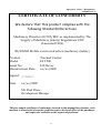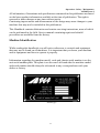
1
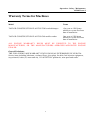
Operation - Safety - Maintenance
10/2005 Issue 9
Operating Manual & Routine Servicing
HiT500
Compact Tracked
Carrier
Taylor Construction Plant Ltd.
Quayside Park, Bates Road,
Maldon, Essex, CM9 5FA
Tel:+44 (0)1621 850777
Fax:+44 (0)1621 843330
[email protected]
www.tcp.eu.com
1
Operation - Safety - Maintenance
10/2005 Issue 9
2
Operation - Safety - Maintenance
10/2005 Issue 9
Table Of Contents
Warranty policy and procedures
Sample certificate of conformity
1. INTRODUCTION
Introduction
Safety Precautions
Machine Identifications
Theft Deterrent Practices
2. SAFETY PRECAUTIONS
General
Preventing Fire Hazards
Precaution Electrical Hazard
Pre-Starting
Starting
Operating
Lubrication and Servicing
Decals
3. CONTROLS AND OPERATING
Operating Controls Diagram
Accelerator
Steering the Machine
Reversing the Machine
4. OPERATING
Pre Starting Inspection
Component Checks
Engine Operation
Starting the Engine
With Jumper Cables
Moving and Stopping
Stopping the Engine
Parking
Loading
Tipping
Average Specific Gravity
3
Operation - Safety - Maintenance
10/2005 Issue 9
4
Operation - Safety - Maintenance
10/2005 Issue 9
LUBRICATION AND SERVICING
Safety Precautions
Lubrication and Servicing
Miscellaneous Servicing Information
Recommended Lubricants
Lubrication Chart
Overall Size Dimensions (Various)
Basic Vehicle Details
Miscellaneous Bolt & Nut Torque Specification
Every 10 Hours of Operation (Daily)
Every 50 Hours of Operation
Every 1,000 Hours of Operation
Every 2,000 Hours of Operation
Replacement of Rubber Track
5
Operation - Safety - Maintenance
10/2005 Issue 9
6
Operation - Safety - Maintenance
10/2005 Issue 9
Warranty Policy and Procedures
Foreword
Thank you very much for purchasing this Taylor Construction Plant Ltd product. We believe that it
will serve you without fail. Ensure that you read the Operator’s Manual carefully before use. With
proper handling and maintenance, this TAYLOR CONSTRUCTION PLANT Ltd product will
provide excellent service over an extended period of time.
Registration
Each machine supplied by TAYLOR CONSTRUCTION PLANT Ltd is accompanied by a
registration card. This card must be completed in full and returned to:
Warranty Manager (email: [email protected])
Taylor Construction Plant Ltd.
Quayside Industrial Park
Bates Road
Maldon
Essex, CM9 5FA
Failure to register your machine may invalidate the manufacturer’s warranty.
Liability
The warranty period begins when the product is delivered to and installed at the first purchaser.
Only genuine parts may be used to carry out repairs. Failure to use only genuine parts may
invalidate the Manufacturers Warranty.
TAYLOR CONSTRUCTION PLANT Ltd will not be held responsible if:
(i)
(ii)
(iii)
(iv)
the machine has been used to perform tasks that demand more than it’s design and
strength limitations, or
the machine has undergone modifications not approved by TAYLOR
CONSTRUCTION PLANT Ltd, or
conditions of use have been abnormal, or
normal maintenance, with regard to requirements as set out and detailed by the
manufacturer, have not been adhered to.
TAYLOR CONSTRUCTION PLANT Ltd will not pay for normal maintenance or servicing nor
any materials used to carry out routine servicing.
The warranty liability of TAYLOR CONSTRUCTION PLANT Ltd is limited to diagnosis, repair
or replacement of the defective part, and actuating the repair - depending on the product terms and
conditions, this will be free of charge.
TAYLOR CONSTRUCTION PLANT Ltd shall be under no liability whatever to the customer for
ant indirect loss and/or expense (including loss of profit) suffered by the customer arising out of a
breach by TAYLOR CONSTRUCTION PLANT Ltd of this contract.
7
Operation - Safety - Maintenance
10/2005 Issue 9
Warranty Audits and Surveys
TAYLOR CONSTRUCTION PLANT Ltd reserves the right to carry out audits and inspections
from time to time in relation to any reimbursed or outstanding warranty claims in order to determine
that all relevant details and information is correct.
Service and Warranty Training
Service and warranty training for service fitters can be requested in writing. Initial training is to be
carried out at an appropriate TAYLOR CONSTRUCTION PLANT Ltd workshop. Once this initial
training has been carried out, you are responsible to carry further training as required by your own
service centre or depot network.
Service Bulletins
TAYLOR CONSTRUCTION PLANT Ltd may from time to time issue service bulletins to keep
you up to date as to any improvements or changes that may take place on the complete assembly or
component parts.
8
Operation - Safety - Maintenance
10/2005 Issue 9
Warranty Terms for Machines
Model
Terms
TAYLOR CONSTRUCTION PLANT Hi-T500 tracked dumper
One year or 1200 hours
whichever occurs first from
date of installation
TAYLOR CONSTRUCTION PLANT Hi-C40 mobile crusher
One year or 1200 hours
whichever occurs first from
date of installation
ALL ENGINE WARRANTY ISSUES MUST BE DIRECTED TO THE ENGINE
MANUFACTURER, OR THE MANUFACTURERS APPROVED/APPOINTED ENGINE
DEALER.
General Exclusions:
THE FOLLOWING ARE WARRANTY EXCLUSIONS AS DETERMINED BY KUBOTA:
Service items including lubricants, coolants, filters, glow plugs, fan belts, fuel injection equipment,
stop solenoid, leaks (oil, water and air), IN ADDITION: paintwork, wear parts and tracks.
9
Operation - Safety - Maintenance
10/2005 Issue 9
Warranty Claim Submission Procedures
Claims must be reported accurately and all relevant details given, as follows:
OWNERS NAME AND ADDRESS: full name and address of customer and site location, if different
MACHINE TYPE: State machine type, i.e. Hi-T500, tracked dumper, Hi-C40, crusher
DATE OF FAILURE:
INSTALLATION DATE: The actual date of installation, not invoice date
SERIAL NUMBER: Serial number of unit
ENGINE NUMBER: Serial number of engine
HOURS USED: Sate hours used on hour clock. Please do not guess the hours used
DETAILS OF FAILURE: Give a full report on the failure
ORDER NUMBER: An order number will be required
Note: the order number is to cover the diagnostic and call out time, as well as to determine the
following:
(i) That the failure is to be covered under the terms and conditions of warranty. If this is the case,
then the costs will be covered by TAYLOR CONSTRUCTION PLANT Ltd and the order number
will not be used.
(ii) If the failure is determined to be of a non-warrantable nature, further authorisation to continue
will be sought before any rectification work takes place.
The information above must be provided even if your warranty claim is a “parts only” claim. An
invoice will be raised for the exchange parts. The reported faulty/defective part must immediately be
returned to TAYLOR CONSTRUCTION PLANT Ltd and full inspection of the parts carried out, if
the failure is covered under the terms and conditions of warranty a credit note corresponding to the
invoice will be despatched to the customer. If the failure is deemed to be of a non-warrantable
nature, the invoice should be settled immediately.
Kubota UK Engine Dealers:
Bryce Group Ltd.
Daimler Close, Royal Oak Industrial Estate, Daventry, Northants NN11 5QJ.
Tel:- 01327- 876166 Fax :- 01327- 300244
[email protected]
www.bryco-diesel-engines.co.uk
C.M.H. LTD.
Maudlins Industrial Estate, Monread Road, Naas, Co Kildare, Eire.
Tel :- 00-353-458-76225 Fax :- 00353-459-7476
[email protected]
Hurley Engine Services.
Unit 7, The Maltings Industrial Estate, Brassmill Lane, Bath, Somerset, BA1 3JL.
Tel :- 01225-336812 Fax :- 01225-442477
[email protected]
10
Operation - Safety - Maintenance
10/2005 Issue 9
J & E Motor Engineers.
23 Polmont Road, Laurieston, Falkirk, FK2 9QQ.
Tel :- 01324-633266 Fax :- 01324-633870
[email protected]
John A Sparks & Co. Ltd.
Western Industrial Estate, Caerphilly, CF83 1BQ,
Tel :- 02920-807080 Fax :- 02920-8707081
[email protected] www.a-sparks.com
Meetens Industrial Engines Ltd.
261-269, Coombe Lane, Wimbledon, SW20 0RH,
Tel :- 0208-9464244 Fax :- 0208-9472595.
[email protected]
Northern Lift Trucks (Northern Ireland) Ltd.
1 Flush Park, Knockmore Road, Lisburn, BT28 2DX.
Tel :- 02892-673111 Fax :- 02892-660618
[email protected]
Phoenix Power Services.
Unit 12, Thames Trading Centre, Woodrow Way, Irlam, Manchester M44 6BP.
Tel :- 0161-775-4053 Fax :- 0161-776-2047.
[email protected]
Sean Cleary & Son Eng.Ltd. I.D.A. Industrial Estate, Dublin Road, Loughrea, Co.Galway, Eire.
Tel :- 00-353-91-841420 Fax :- 00-353-91-842823
[email protected]
Sleeman & Hawken Ltd.
Bridge Road, Shaldon, Devon, TQ14 ODD.
Tel :- 01626-872750 Fax :- 01626-873767.
[email protected]
Trucks Morley Ltd.
Bruntcliffe Road, Morley, Leeds, LS27 0JZ
Tel :- 0113-2526777 Fax :- 0113-2380310.
[email protected]
Universal Engine Power Ltd.
Unit 9, Flitch Industrial Estate, Chelmsford Road, Great Dunmow, Essex, CM6 1XJ.
Tel :- 01371-875331 Fax :- 01371-874777
www.unipower.uk.com
[email protected]
Wood Leigh Power Equipment Ltd.
Unit 20, Highcroft Industrial Estate, Enterprise Road Horndean Waterlooville Hants PO8 0BT.
Tel :- 02392-571360 Fax :- 02392-592056.
[email protected] www.woodleighpower.co.uk
Yardbury Kinetics Ltd.
Altens Trade Centre, Hareness Circle, Aberdeen AB12 3LY
Tel :- 01224-897947 Fax :- 01224-872374
[email protected]
11
Operation - Safety - Maintenance
10/2005 Issue 9
CERTIFICATE OF CONFORMITY
We declare that this product complies with the
following Standards/Directives.
Machinery Directive 89/392/EEC as implemented by The
Supply of Machinery (Safety) Regulations 1992
(Amended 1994).
BS/EN500 Mobile road construction machinery (Safety)
Product
Model
Serial No
Manufacturer Date
:Tracked Carrier
:HiT 500
:HT-Bxxxx
:xx/xx/2002
Signed:
Date:
xx/xx/2002
Mr Paul Drew
Development Manager
This is a sample certificate of conformity inserted in this manual for reference, each
machine is issued with a bespoke certificate sent to the head office of the purchaser,
and copies are available on the request of purchaser.
12
Operation - Safety - Maintenance
10/2005 Issue 9
1. Introduction
Please read carefully and understand before operating the equipment.
This Handbook is provided as a guide to familiarise the operator and service engineer
with the controls, recommended inspections, start-up, operating, and shutdown
procedures for HiT range of equipment.
Safety Precautions
This piece of equipment is designed as a compact tracked carrier with the
carrying capacity of 500 Kg only.
At all times loads should carried with the body in the low position and raised
for tipping only when the unit is stationery
FAILURE TO COMPLY WITH WARNINGS COULD RESULT
IN SERIOUS PROPERTY DAMAGE AND POSSIBLE
PERSONAL INJURY.
The machine should be properly operated and maintained to keep it in safe efficient
operating condition. Be sure that all controls are free of mud, grease, or other matter
that might cause slips hazardous to the operator, serviceman, or other personnel or
equipment.
Report all malfunctions to those responsible for maintenance. Do not operate the
equipment until corrected. Normal service or maintenance performed as required can
prevent unexpected and unnecessary down time. This handbook describes general
inspections, servicing and operation with the normal safety precautions required for
normal servicing and operating conditions. It is not a guide however, for other than
normal conditions or situations.
Operators and Servicemen must be safety conscious and alert to recognise potential
operating or servicing safety hazards at all times, and take, necessary precautions to
ensure safe operation and servicing of the machine.
13
Operation - Safety - Maintenance
10/2005 Issue 9
All information, illustrations and specifications contained in this publication are based
on the latest product information available at the time of publication. The right is
reserved to make changes at any time without notice
Continuing improvement and advancement of the design may cause changes to your
machine that may not be included in this publication.
This Handbook contains lubrication and routine servicing instructions, most of which
can be performed in the field. Service manual containing repair and rebuild
procedures are available from the factory.
Machine Identification
Whilst reading this handbook you will notice references to controls and equipment
that may not be found on all machines. It is important that you know your machine
and its equipment and how to operate it properly.
Information regarding the machine model, code and chassis serial number is on the
unit serial number plate. This plate is on the rear Left-hand side the machine model
and serial number should always be referenced in any correspondence with your
dealer or factory.
Data Plate (fig 1)
14
Operation - Safety - Maintenance
10/2005 Issue 9
Theft Deterrent Practices
The owner/operator should take the following precautions to discourage theft, to aid
in recovery in the event that the machine is stolen, or to reduce vandalism.
Actions to Discourage Theft and vandalism
• Remove all keys any time the machine is left unattended.
• Immobilise the machine by removing a critical electrical or starting system device.
• Upon receipt of a machine, record the machine serial number and the serial
numbers of all-major components and attachments. Keep this list up to date and
filed in a safe location for fast retrieval.
• Place a decal or notice on the machine stating that all serial numbers are recorded.
• Discourage the thief! Inspect the gates and fences of the machinery storage yard or
construction site. Keep machines in well-lit areas and ask the local law
enforcement authorities to make frequent checks around the storage yard or work
site.
• Establish liaison with neighbours and ask them to watch equipment left at job sites
and to report any suspicious activities to local allow enforcement authorities.
• Make frequent inventories of machines to promptly detect losses or vandalism.
Actions to aid in recovery of stolen machines
In the event of theft, immediately notify the law enforcement authorities having
jurisdiction. Provide the investigating officer with name, type of equipment, chassis
and serial numbers of major attachments and components. It would be helpful to
show the investigating officer an Operator’s Handbook, photographs, and advertising,
to familiarise him with the appearance of the machine.
Report the theft to the insurance company. Provide the model and all serial numbers.
Report the model and serial numbers of the stolen machine to a dealer handling the
respective line of equipment. Request that the dealer forward this same information to
the equipment manufacturer.
15
Operation - Safety - Maintenance
10/2005 Issue 9
2. Safety Precautions
General
• Read this operator’s Handbook and learn the operating characteristics and
limitations of the machine. Know what operating clearances the machine requires.
• Know clearances of all side and overhead obstructions such as wires, etc., for
operating safety.
• Be aware of operating hazards that weather changes can create on the job. Know
proper procedures to follow when a severe rain or electrical storm strikes.
• Never attempt to operate or work on a machine when not feeling physically fit.
• Know what safety equipment is required and use it. Such equipment may be
hardhat, safety glasses, reflector type vests, respirators and earplugs.
• Never wear loose clothing, rings, and watches etc. that might catch levers and
controls and cause loss of control.
• Keep hand controls free from water, grease and mud to assure non-slip control.
• Handle fuels and lubricants carefully and clean up spills to avoid fire and slipping
hazards.
• Never rush. Walk do not run.
16
Operation - Safety - Maintenance
10/2005 Issue 9
Preventing Fire Hazards
General Fire Precautions
• Clean all dirt, oil, grease and other fluids from systems and components to
minimise fire hazards and aid in spotting loose or leaking lines, fittings etc.
• Check the engine for rubbish, oily rags or other debris that could cause fires before
starting the engine.
• Safely dispose of greasy, oily rags or similar hazards.
• Flammable Fluid Precautions
• Don’t use diesel fuel or other flammable fluids for cleaning purposes. Use approved
non-flammable solvents.
• Make sure all-fluid systems caps, drain, valves, fittings, lines etc., are secure and
leak free.
• Never use an open flame (match, lighter etc.) when checking fuel, lubricant,
coolant and battery fluid levels or when checking for fluid leaks. Use a flashlight or
other safe lighting only.
• Shut off engine and use extra caution if engine is hot when refuelling.
Never smoke while checking or adding fuel or other fluid or handling fluid
containers and lines.
• Use care and do not stand downwind when adding fuel or other flammable fluids
to tanks and reservoirs to avoid fluids being blown or splashed onto clothing.
• Close fuel tank shut-off valves, if used, before servicing fuel system.
• When preparing machines or components for storage, seal and tape all openings
and close containers tightly to seal in all volatile inhibitor fluids and compounds
used.
• Follow manufacturer’s recommendations when handling and using engine-starting
fluids and disposing of spent containers. Do not puncture or burn empty
containers. These fluids are explosive and highly flammable.
17
Operation - Safety - Maintenance
10/2005 Issue 9
Precautions Electrical Hazard.
• Never smoke or allow open flames or sparks near batteries.
• Leave battery box open when charging batteries in machine for adequate
ventilation of explosive gas (Hydrogen) produced.
• Always disconnect batteries before repairing electrical system to avoid danger of
fire-causing sparks. Disconnect battery ground cable first and reconnect last.
• Always disconnect batteries and alternator leads before carrying out any welding
on the machine.
• Never check battery charger by placing metal objects across battery posts to avoid
sparks at battery posts.
• Use jumper cables only as recommended. Improper use can result in battery
explosion or unexpected machine motion.
• Never operate engine starter for more than 15 seconds and allow 30 seconds
between cranking periods for cooling. An overheated starter could cause a fire.
Pre-Starting
• If engine is to be started and run indoors, ensure proper ventilation to remove
deadly exhaust gases.
• Always perform ‘Pre-Starting Inspection’ instructions described in this manual to
ensure the machine is ready for operation.
Starting
• Do not start the engine or operate any control if there is a ‘DO NOT OPERATE’
or similar warning sign attached to any control.
• Use jumper cables only as recommended. Improper use can result in battery
explosion or unexpected machine motion.
• Always obey ‘Starting the Engine’ instructions.
• Start and operate the machine only from the operator’s station.
18
Operation - Safety - Maintenance
10/2005 Issue 9
Operating
• Always perform ‘Pre-Operating Checks’ described in this manual to ensure the
machine is ready for operating.
• Do not operate the machine if exposed personnel enter the immediate work area.
• Be sure the body is fully down before moving the machine-warning buzzer will
sound if body is not fully down.
• Always try to face or look in the direction the machine is travelling.
• Always operate straight up or down slopes whenever possible. Side-hill operation
can cause sideslip and possible rollover.
• Slow down when moving in congested areas. Do not race with other machines.
Stop in authorised areas only, except in an emergency.
• Always watch for holes, soft edges or other hazards when dumping over a spoil
bank.
• Operate body raising mechanism on firm level surface only, a buzzer will sound to
warn the operator and others in the area once the body raises above horizontal.
Lubrication and Servicing
• Do not allow unauthorised personnel to service or maintain the machine. Study the
Operator’s handbook and Service Manual before starting, operating or servicing
the machine.
• Do not work under or near unblocked or unsupported body. Always invert the
empty body.
• Do not work under or near any unblocked or unsupported linkage, part or
machine.
• Always relieve pressure before servicing any pressurised system.
19
Operation - Safety - Maintenance
10/2005 Issue 9
Decals
Decals fitted to machines may vary from country to country to suit local needs. These
pages contain a brief description and the location of the decals and control plates that
may appear on this machine.
Ref
1
2
3
4
5
6
7
8
9
10
11
12
Part
Number
80-0001
80-0002
80-0003
80-0004
80-0005
80-0006
80-0007
80-0008
80-0009
80-0010
80-0011
80-0012
Part Name
Qty
"Serial Data Plate"
"Control Panel Decal" (state year)
"Warning Crush Zone"
"Warning Hot Exhaust"
"Hydraulic Oil Filler"
"Fuel Filler"
"CE Marking
"Hoisting Point"
"Danger Keep Clear"
Logo Body "H T 500" Left/Right Hand
P T O (Optional)
Hydraulic Oil filter and dipstick
1
1
6
2
1
1
2
1
2
2
1
1
Decal Layout (fig 2)
20
Operation - Safety - Maintenance
10/2005 Issue 9
3. Controls and Operating
Operating Control Diagram
A view of the handlebar and control (2002) (fig 3)
21
Operation - Safety - Maintenance
10/2005 Issue 9
Engine Accelerator
This is mounted on the left-hand side of handlebar assembly and is operated by the
hand. Press the lever down as required to increase fuel flow to accelerate the engine.
Do not place engine under full load at full speed immediately after starting. Always
allow the engine to fully circulate lubricant and warm up gradually before operating at
full speed and full load. Operate the engine at top rated speed when maximum power
is needed for maximum speed and load.
Steering Via Hydrostatic Drive
The steering is performed by:
• To steer the machine, apply differing pressure to the control levers.
• Apply equal pressure on both levers to the forward position will make the machine
move forward in the desired direction at speed.
• The machine will turn only when more or less pressure is applied to either lever
proportional to the lever movement
To operate in the opposite direction.
The Reverse procedure is performed by:
• Apply equal pressure on both levers to the reverse position will make the machine
move backward in the desired direction at speed.
• The machine will stop and hold any position when the both levers are released
(Dead-man Brake)
22
Operation - Safety - Maintenance
10/2005 Issue 9
4. Operating
Operating
Pre-starting Inspection
• Before the engine is started ensure the machine is ready for operation
• The machine should be in a level position to permit accurate checking of fluid
quantities in the engine and other components.
• Walk around the machine and carry out the Inspections and Components
Checks described on the following pages.
Daily Component Checks
• Reference should be made to engine manufactures handbook.
• Engine - With engine off, check oil level. The level should be just over the last
thread at filler Add oil if low. (See lubricant chart for correct oil).
• Inspect the engine air cleaner for any damage (replace immediately. Using an
engine with a damaged air cleaner will seriously reduce engine life)
THESE INSTRUCTIONS MUST BE ADHERED TO IN ORDER TO
ASSURE CONTINUANCE OF ENGINES WARRANTY.
• Carefully inspect tracks for cuts, or other damage, and correct spring preload.
• Inspect for any leaks whether fuel, engine oil or hydraulic oil.
• Check fuel level - Fuel tank should be filled at end of each shift.
23
Operation - Safety - Maintenance
10/2005 Issue 9
Engine Operation
Do not place engine under FULL LOAD at FULL SPEED IMMEDIATELY after
starting. ALWAYS allow the engine to fully circulate lubricant and warm up gradually
before operating at full speed and full load.
Operate engine at top rated speed when maximum power is needed for the load.
NEVER IDLE THE ENGINE FOR MORE THAN 5 MINUTES AT A TIME.
SHUT IT OFF.
If operated outside its normal operating range, shut engine down immediately and
report to service or maintenance personnel.
WARNING
Never start the engine indoors unless proper exhaust ventilation is provided to remove
deadly exhaust gases. Once the engine is running, move the machine outdoors as soon
as possible. Exhaust gases are hazardous and can cause unconsciousness and death.
Operating the engine beyond high idle speed can cause severe engine damage. The
engine speed must not exceed 3,600 rev/min under any circumstances. When
descending a steep grade, use a combination of lever and engine speed.
Starting the Engine
1. Make sure that all levers are in the neutral position.
2. Insert switch key and turn clockwise to position ‘1’ to switch on the ignition. (Run
position)
3. If engine is cold turn to pre heat position ‘2’ and hold for 20 seconds
4. Turn key further clockwise against spring pressure to position ‘3’ to crank engine;
release key as soon as engine starts firing.
NOTE:
Never crank the engine for more than 15 seconds continuously.
Allow starter at least 30 seconds cooling time between cranking periods to avoid
overheating.
24
Operation - Safety - Maintenance
10/2005 Issue 9
Starting the Engine with Jumper cables.
To access the battery you will be need to tip the body forward in the down position to
gain access to the cover plate, remove the 3 bolts that secure it to the chassis once this
has been done you can remove the plate and locate the battery
WARNING CHARGING OF ODYSSEY BATTERIES
Check for polarity connections of the discharged battery.
Do not exceed 15 volts during charge. Excessive booster voltage and/or incorrect
jumper cable connections will destroy working plates inside battery. Keep all
sources of ignition away from batteries. Do not lean over batteries.
Do not allow the battery to become full discharged you may find that it can not be
recover from this state rendering it unserviceable
Voltmeter Reading
12.84 Volts
12.50 Volts
12.18 Volts
11.88 Volts
State of charge
100%
75%
50%
25%
Do not jump start a vehicle by using arc welding equipment. Currents and voltages are
dangerously high and cannot be sufficiently reduced to make the method safe.
NOTE: Be sure machines are not touching each other. Use cables that are equal to
cable size on the machine.
If jumper cables are used to start an engine, be sure to follow this procedure:
Connect one end of a jumper cable, usually coloured red, to the discharged battery
‘POSITIVE’ (+) post.
Connect the other end of the same cable to the ‘POSITIVE’ (+) post on the booster or
charged battery.
Connect one end of the second cable, usually coloured black, to the
‘NEGATIVE’ (-) post of the booster battery.
Connect the other end of the ‘NEGATIVE’ (-) cable to machine frame for grounding
so that if a spark occurs, it is away from battery fumes (explosive hydrogen).
Check for cause of failure on the dead battery.
25
Operation - Safety - Maintenance
10/2005 Issue 9
Moving and Stopping
1. Make sure the area around the machine is clear of personnel and obstructions
before moving off.
2. In the first few minutes of travel check carefully for the required controls for
maximum operating safety.
3. Make sure the body is fully down, buzzer will sound if in the raised position.
4. Select the driving direction and the required engine speed.
5. Move levers to the required position; apply more accelerators until the required
speed has been reached.
6. To stop the machine release the control levers slowly and release the accelerator as
the machine slows until it stops.
Stopping the Engine
1. Cool a hot engine by operating the engine at 1,000 rev/min and then slowly
decelerating it over a 5-minute period until the engine is idling. Let it idle for at
least 2 minutes. ALWAYS COOL A HOT ENGINE GRADUALLY BEFORE
SHUTTING IT OFF.
2. Turn ignition key switch off to shut off fuel and stop engine.
3. Make sure body is in the lower position.
Parking
When parking the machine overnight, or for an extended period, the following
procedure in addition to that given in ‘Stopping the Engine’ will help maintain it in
good condition for subsequent use:
1. Fill the fuel tank completely before parking the machine overnight or for extended
periods, to prevent condensation. If security kit is supplied, keep it locked
2. Always park on level ground where possible. If it must be parked on a slope,
position machine at right angles to the slope and block tracks securely.
3. Remove key to a place of safety
26
Operation - Safety - Maintenance
10/2005 Issue 9
WARNING
Check tracks, hoses, wiring, tubing and fittings for cuts, abrasion, fraying, or other
damage or deterioration. Inspect for damage to the body or chassis.
Attach warning signs to the controls to alert others if lubricant has been drained,
batteries removed etc.
Loading
The most common methods of loading this type of machine is with hydraulic excavators,
or by hand, these units can be loaded equally well from the front or the side. Ideally,
excavators should require 90° or less swing.
Always position the machine on a level firm surface for loading and leave the loading
area until indicated by loader driver.
The following precautions should be observed when approaching the loading area and
while being loaded wait until it is safe to return to the machine.
Avoid over filling the dump body. Spillage could damage the tracks and other
components. Clear up such debris (see fig 4).
Do not load with machines that are over large and would allow material and fill to fall
from the bucket missing the body. This can be dangerous to both operator and the
unit.
Pay attention to site conditions to avoid rocks, holes, or other obstacles.
Such obstacles present hazards to safe operation, but also can needlessly damage
tracks.
Tipping
The tipping operation usually depends on the type of material being hauled.
Be aware of other personnel within the operating area.
A warning buzzer sounds whenever the body is raised above the horizontal position,
this is as a general warning to the operators and other personnel in the operators’ zone
to take necessary care and precautions.
If tipping at low level, ensure you are clear of all obstacles within the tipping arc of the
body. It is possible to fully invert the body of the Hi-T tracked carrier, care must be
27
Operation - Safety - Maintenance
10/2005 Issue 9
taken that the load to be discharged will readily leave the body once tipping
commences. A retained load may result in machine instability.
Never leave a machine loaded over night, or load with a material that could settle with
the engine ticking over for a long period.
Always clean the body of any retained load for efficient safe working.
Be aware of any precautions and additional safety equipment that may be needed
when handling, hazardous, caustic or cementious materials.
If in doubt seek advice.
Before discharging the load, the machine must be on firm level ground.
If one track is higher than the other, a twisting strain is imposed upon the body hinge
pins and chassis. This could result in machine instability and damage.
Use the control levers to position the body. Operate from the designed operating
position only, keep clear of the tipping mechanism injury could occur. Once the load
has been tipped, move the control levers into the ‘DOWN’ position.
If the load does not clear completely, the built in stops in the mechanism may used to
assist discharge, the cylinder does not need to be retracted before extending again.
To tip into a waste skip choose a position that will allow the body to fully discharge its
load, raise the body only with the machine stationary, once raised the machine may be
inched forward until the tracks contact the side of the waste skip. The body can then
be tipped to discharge load.
28
Operation - Safety - Maintenance
10/2005 Issue 9
Average Specific Gravity
Material
Loose Density
kg/m3
Snow (Fresh)
Peat (Dry);
Sugar beet
Coke (Loose)
Barley
Petroleum Coke
Wheat
Coal Bituminous
Fertilizer (Mixed)
Coal Anthracite
Earth (Dry)(Loose)
Nitrate Fertilizer
Sodium Chloride (Dry)(Salt)
Cement Portland
Limestone (Crushed)
Sand (Dry)
Asphalt
Gravel (Dry)
Clay (Wet)
Sand (Wet)
Fire Clay
Ready Mixed Concrete
Copper (Concentrate)
Slate
Magnetite
200
400
530
570
600
680
730
765
1030
1046
1150
1250
1300
1440
1530
1550
1600
1650
1680
1890
2080
2194
2300
2800
3204
Specific Gravity (fig 4)
29
3
Ib/yd
337
674
894
961
1012
1146
1231
1290
1737
1764
1939
2180
2192
2428
2580
2613
2698
2782
2832
3187
3507
3698
3878
4721
5402
Fill Factor
%
100
100
100
85
85
85
85
100
85
100
100
85
85
100
100
100
100
85
110
110
100
85
85
100
100
Operation - Safety - Maintenance
10/2005 Issue 9
5. Lubrication and Servicing
SAFETY PRECAUTIONS
Do not allow unauthorised personnel to service or maintain this machine. Study the
Operator’s Handbook and Service Manual before staring, operating or servicing this
machine. Always follow procedures and safety precautions detailed in this manual.
Do not work under or near an unblocked or unsupported body. Always invert the
empty body.
Do not work under or near any unblocked or unsupported linkage, or any part of
machine.
Always shut down machine according to the procedure described under ‘Stopping The
Engine’ before cleaning, lubricating or servicing the machine
Always relieve pressure before servicing any pressurisation system.
Always attach a ‘DO NOT OPERATE’ or similar warning sign to ignition switch or a
control before cleaning or servicing the machine.
LUBRICATION AND SERVICING
Lubrication is an essential part of preventive maintenance. It is important that the
instructions regarding types of lubricants and the frequency of their application be
followed to prolong the useful life of the machine. Periodic lubrications of moving
parts reduce to a minimum the possibility of mechanical failures.
Thoroughly clean all fittings, caps, plugs etc., to prevent dirt from entering the system
while servicing.
Lubricants must be at operating temperatures when draining.
Do not operate any system unless oil level is within the operating range as indicated
on the dipstick, or level plug.
All change and service periods are recommendations based on average operating
conditions. Lubricants showing evidence of excessive heat, oxidation or dirt should be
changed more frequently to prevent these conditions. Lubricants change and service
periods must be established on the basis of individual job conditions.
30
Operation - Safety - Maintenance
10/2005 Issue 9
Miscellaneous Servicing Information
When required:
• Hydraulic Tank - Cold Oil Level –
• Hydraulic oil dipstick is not used to checked oil it is there to allow the air in the
tank to be displaced when filling.
• To ad oil, remove red top of filter, pull out filter, and remove dipstick, if low fill
through the filter housing until the level is 6mm below the tube in the base of
the filter housing.
Recommended Lubricants
Note: Do not mix Lubricants
Item No Component
1
2
3
4
Lubricant
Specifications
Engine
Crankcase and
Filter
Hydraulic
System
API
SAE
Code
Grade
CC/CD 10W-30
Engine Oil with
1.85% max.
Sulphated ash limit
6743-4D 46CS
Hydraulic oil
HV 36 or
Bio-Degradable
Liquimatic BVG
36/Plantosyn 36
HVI
Fuel tank
Diesel Fuel Oil
A.S.T.M. No.2
with max. Sulphur Diesel Fuel (at
0.5%
sub zero temp.
blend No. 2 with
No.1
No. 2
Grease Nipples Extreme Pressure Stern Tube
Consisten
Lithium (No
Grease C/W
cy
'Moly')
Extreme
Pressure
Capabilities
Lubrication Chart (fig 5)
31
Operation - Safety - Maintenance
10/2005 Issue 9
Lubrication Layout (fig 6)
32
Operation - Safety - Maintenance
10/2005 Issue 9
“Basic Overall Dimensions”
(fig 7)
33
Operation - Safety - Maintenance
10/2005 Issue 9
General Specification
Hi-
Diesel
T 500
500 (1100 )
Maximum Carrying Capacity
Kg (lbs)
Skip Volume
Lt (ft ³)
255 (9.0)
Unladen Weight
Kg (lbs)
448 (987)
Width
mm (ins)
700 (28 ins)
Height
mm (ins)
1165 (45.8 ins)
Height Over Skip
mm (ins)
2500 (98.4 ins)
Height Under Skip
mm (ins)
1200 (47 ins)
Length
mm (ins)
1770 (69.6 ins)
Max Gradeability
%
Turning Circle
mm (ins)
2000 (78.5)
Track Ground Pressure
Kg/cm ² (psi)
0.351 (4.99)
Engine (All with Electric Start)
kW (HP)
Speed Forward
Kph (Mph)
4 (2.5)
Speed Reverse
Kph (Mph)
2 (1.2)
Power Take Off
45%
Kubota OC95 7.1 (9.5)
20 lt/m @ 120 bar
Optional
Lwa
101
Noise Level
General Specification (fig 8)
34
Operation - Safety - Maintenance
10/2005 Issue 9
Miscellaneous Bolt & Nut Torque Specification
Friction coefficient total 0.14 for screws and nuts without after treatment as well as for
phosphate nuts.
Tighten by hand.
If nothing special is indicated select correct torque limits from the following tabulations:
Metric ISO Thread DIN 13
Size
6.9
Some Engine Bolts
10.9
Some Engine Bolt
8.8
Standard Hex Bolt
12.9
Standard Cap head
M6
Nm
8.5
(Ibfft)
(6.3)
Nm
10
(Ibfft)
(7.4)
Nm
14
(Ibfft)
(10.3)
Nm
17
(Ibfft)
(12.5)
M8
M10
21
41
(15.5)
(30.2)
25
49
(18.4)
(36.1)
35
69
(25.8)
(50.9)
41
83
(30.2)
(61.2)
M12
M14
72
115
(53.1)
(85)
86
135
(63.4)
(100)
120
190
(88.5)
(140)
145
230
(106.9)
(170)
M16
180
(133)
210
(155)
295
(218)
355
(262)
M18
M20
245
345
(181)
(255)
290
410
(214)
(302)
400
580
(295)
(428)
485
690
(358)
(509)
M22
M24
465
600
(343)
(443)
550
710
(406)
(524)
780
1000
(575)
(738)
930
1200
(686)
(885)
M27
890
(656)
1050
(774)
1500
(1106)
1800
(1328)
M30
1200
(885)
1450
(1070)
2000
(1475)
2400
(1770)
Torque Settings (fig 9)
35
Operation - Safety - Maintenance
10/2005 Issue 9
Every 10 hours of operation (Daily Walk Around Inspection)
• Visually check engine for damage, listen for any unusual noises:
• Engine Air Cleaner, Inspect and remove any obstructions from the air cleaner
inlet with the engine stopped:
• Check Engine oil level, add oil if low see lubrication chart, With the engine off,
the oil should be just over the last thread at filler: (Note do not over fill)
Fabrications:
• Lubrication (greasing) Periodic lubrications of moving parts reduce to a
minimum the possibility of mechanical failures:
• Check for any loose bolts or fixings, tighten as per bolt chart:
• Check for any oil leak’s securely tighten any loose joints, replenish any loses:
NOTE:
• Service air cleaners more often when operating under extremely dusty
conditions.
• Do not wash the air cleaner element out with detergent replace with new
After first 50 hours of operating new or rebuilt components
• With the engine off and body inverted, remove red top of filter, pull out filter.
• Check level refill hydraulic tank as per lubrication chart. Check oil level by
remove dipstick if low fill through the filter housing until the level is 6mm below
the tube in the base of the filter housing:
• Replace the hydraulic oil filter install new element each time do not reuse.
• Engine crankcase, drain oil replace as per lubrication chart check oil level the oil
should be just over the last thread at filler: (Note do not over fill)
• Lubrication (greasing) Periodic lubrications of moving parts reduce to a
minimum the possibility of mechanical failures:
Every 100 hours or operation (Monthly)
• Engine crankcase drain oil replace as per lubrication chart check oil level the oil
should be just over the last thread at filler: (Note do not over fill)
• Lubrication (greasing): -periodic lubrications of moving parts reduce to a
minimum the possibility of mechanical failures:
• General inspection check entire unit for leaks loose bolts and nuts or damaged
parts. Examine the body, particularly the chassis, for cracks or broken welds.
Repair where necessary.
36
Operation - Safety - Maintenance
10/2005 Issue 9
• Engine air intake. Check air intake system for wear or damage to piping, loose
clamps and leaks.
• Drain fuel remove filter screen replace the assemble install new filter screen and
refill tank. If contaminated fuel is suspected frequency may need to be
increased.
Every 300 hours of operation
• Drain fuel and replace fuel filter.
• Lubrication (greasing): -Periodic lubrications of moving parts reduces to a
minimum the possibility of mechanical failures.
Every 1,000 hours of operation (6 Months)
• Lubrication (greasing): -Periodic lubrications of moving parts reduces to a
minimum the possibility of mechanical failures.
• Replace hydraulic oil filter install new element each time do not reuse.
Every 2,000 hours of operation (Annually)
• Lubrication (greasing):- Periodic lubrications of moving parts reduces to a
minimum, the possibility of mechanical failures.
• Hydraulic Oil Tank:-Drain oil, remove and clean filter screen assemblies.
Reinstall filter screens and refill tank.
• Hydraulic Oil Filter Clean filter housing and install new element after a year or
2,000 hours of operation whichever comes first.
All information contained in the ‘Lubrication and Service Chart’ is extracted from the
relevant manufactures Operators Manual and was correct at time of publication. User
should ensure that information contained in this chart, regarding engines and
hydraulics, reflect the information shown in the relevant manufacturers Operators
Manuals, supplied with the machine. Maintenance procedures should be carried out
in conjunction with any additional procedures contained in the relevant
manufacturers ‘Operation and Maintenance Manual’, at the intervals specified.
Lubrication and Miscellaneous Servicing
Small circles on the illustration represent points at which lubrication or servicing must
take place, at the intervals indicated on the left-hand side of the lubrication chart.
37
Operation - Safety - Maintenance
10/2005 Issue 9
Note 1. The use of low viscosity oils, such as 10W or 10W - 30, can be used to
aid in starting the engine and providing sufficient oil flow at ambient temperatures
below -5°C (23°F). Continuous use of low viscosity oils can decrease engine life due to
wear.
Note 2. Operation below the minimum temperatures listed for the oil used
without proper preheats or warm-up results in greatly reduced life. Proper warm-up
requires 20 minutes minimum (with engine at part throttle) before operating.
Note 3. Hydraulic Oil meeting specification is the only oil suitable for use in this
hydraulic system.
38
Operation - Safety - Maintenance
10/2005 Issue 9
Replacement of Rubber Drive Track
In the event that the drive Track being displaced during operation follow the
procedure listed below.
Typical view of displaced track
Support lower chassis along its length
Remove blanking plugs
lubricate jacking bolts (supplied)
Insert jacking bolts adjust equally
Adjust until idler is in line with roller
39
Operation - Safety - Maintenance
10/2005 Issue 9
Remove blanking plug
Remove securing bolt
Remove Idler
Place Idler in drive track
Slide drive track and Idler on shaft
Insure Idler is fully home
40
Operation - Safety - Maintenance
10/2005 Issue 9
Install securing bolt (torque 49Nm)
Replace blanking plug
Remove jacking bolts
Replace blanking plugs
Remove any blocking under chassis run and test.
41
Operation - Safety - Maintenance
10/2005 Issue 9
42
Operation - Safety - Maintenance
10/2005 Issue 9
43
Operation - Safety - Maintenance
10/2005 Issue 9
44
Operation - Safety - Maintenance
10/2005 Issue 9
45
Operation - Safety - Maintenance
10/2005 Issue 9
46
Operation - Safety - Maintenance
10/2005 Issue 9
47
Operation - Safety - Maintenance
10/2005 Issue 9
48
Operation - Safety - Maintenance
10/2005 Issue 9
49
Operation - Safety - Maintenance
10/2005 Issue 9
50
Operation - Safety - Maintenance
10/2005 Issue 9
51
Operation - Safety - Maintenance
10/2005 Issue 9
52
Operation - Safety - Maintenance
10/2005 Issue 9
53
Operation - Safety - Maintenance
10/2005 Issue 9
NOTES:
54