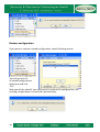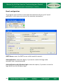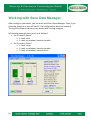
1
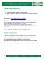
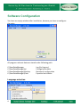
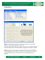
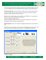
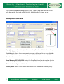
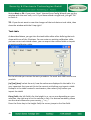
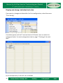
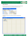
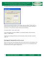
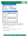
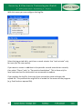
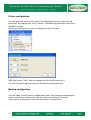
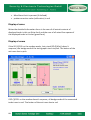
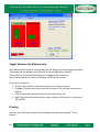
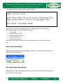
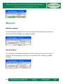
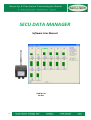
SECU DATA MANAGER
Software User Manual
SDM M E 01
05 2011
1
TOC – Table of Contens
Software Installation .......................................................................................................... 3
Software Update ................................................................................................................ 3
Software Configuration ..................................................................................................... 4
Language selection ....................................................................................................................... 4
Config Wizard................................................................................................................................. 5
Setting of the tank data ................................................................................................................ 7
Tank table ..................................................................................................................................... 10
Display and change individual tank data ................................................................................. 12
Probe calibration.......................................................................................................................... 13
Exchange of tank position on the screen ................................................................................ 14
Configure the log file ................................................................................................................... 15
Printer configuration .................................................................................................................... 17
Backup configuration .................................................................................................................. 17
Restore configuration.................................................................................................................. 18
Email configuration...................................................................................................................... 19
Working with Secu Data Manager .................................................................................. 21
Tank display ................................................................................................................................. 22
Detailed information of the selected tank ................................................................................ 22
Display of sums ........................................................................................................................... 23
Display of errors........................................................................................................................... 23
Toggle between the different sets ............................................................................................ 24
Printing .......................................................................................................................................... 24
Send email immediately ............................................................................................................. 25
Get modem data immediately ................................................................................................... 25
Manuals ............................................................................................................................ 26
Software manual.......................................................................................................................... 26
Device manual ............................................................................................................................. 26
Important: The technical specification stated in this document is subject to modification by the
manufacturer without any notice!
© SECURITY & ELECTRONIC TECHNOLOGIES GmbH.
2
Software Installation
Conditions:
• PC with Windows XP, Windows Vista or Windows 7
• RS232 or USB/RS232 converter and/or modem (internal, external, line or
GSM)
• Internet connection
Installation link: http://www.secu-tech.at/software
The program is based on Microsoft .NET 3.5 SP1. If this software isn’t installed
on your computer, it will be installed automatically. Please be patient in this
case, in some cases it can take more than 30 minutes.
Make sure that you have administrator rights to install it on your PC.
After installation the program starts immediately. The next time you find the
program at:
START – Programs – Security & Electronic Technologies GmbH
Software Update
If your PC has a permanent Internet connection, there is a check for software
updates each program call. Because of permanent improvement of the
software several update in short time are possible.
In this case, you will be asked if you want to install the update.
Remember that you need administrator rights on your PC to install the update.
If you have a shortcut of the program on the desktop, you have to make a new
one, because the update is located on another location on the hard disk.
3
Software Configuration
You have an empty window after installation, because you have to configure
the tanks.
All program-relevant data are stored under following path:
C:\SecuDataManager
C:\SecuDataManager\Ini
C:\SecuDataManager\Backup
C:\SecuDataManager\Data
Language selection
4
Log file (Log.csv)
Configuration data
Backup of configuration
Exported tank tables
Config Wizard
RS232: select this if a SD (1) 232L is directly connected via a serial RS232
interface or USB / RS232 converter on your PC.
If you have selected this field, the program searches for all available interfaces
to find the SD (1) 232L. The COM interface is displayed if one device is found.
GSM: select this if you work with a far away tank farm, where a SD(1)232L is
installed together with a modem. Your PC must be connected to a modem or
an internal modem may be present. Both a line and a GSM modem are
possible.
5
After selecting this field, the program search for all installed modems. Are one
or more modems found, you should select the right one of the displayed list.
Each hour/each day: if you work with a modem, you can select the period to
call the far away stations, once per day or once per hour. Shorter periods
would not make sense for financial reasons.
Set: with Secu Data Manager you can define up to 100 tanks. It is possible to
define 5 screens (sets) to maximum 20 tanks.
Select the wished number of sets.
You can change the name of the sets (maximum 6 characters). The name is
displayed on the set-button on working area.
Number of tanks: select the number of displayed tanks for the set (maximum
20).
X/Y: define the tank division on the screen by changing the parameter X. X sets
how many tanks are displayed horizontally. Y is calculated automatically.
Example with 3 sets (screens). The local SD (1)232 is connected to COM20, the
modem to COM23.
6
If you have finished the configuration, press „Next“. Now you have to set the
tank data of the first tank of the first set. After this, the 2nd tank, a.s.o.
Setting of the tank data
Top right you see the set-text, in this example: „Petrol“ and the tank number,
here „1“ of „2“ tanks.
Depending on where the cursor points, you see a help graphic on the right side.
In the example above, you see how you can find the serial number of the Secu
Data Level device.
Serial Number SD(1)420/421L: enter the Secu-Data-Level serial number (device
on the tank). The serial number can be found outside and inside of the unit.
This is the last 5 digits on the label.
RS232 / GSM: select if this tank is local (RS232) or remote via modem (GSM).
7
Phone number of the tank modem: if you have selected „GSM“, you can enter
here the target phone number of the modem. If there are several tanks at this
station, you can select the phone number on the "drop-down" function of this
field. Enter the phone number with the international code, e.g.
„+4366422233355“.
Tank Name: this is the short name of the tank. At default the name is a
combination of set-name and tank number (in the example above:
“Petrol1/1”). You can enter here your own tank name.
Tank Description: this is for a detail description of the tank.
Product: enter your own product name or select one of the drop-down box.
Density [kg/m3]: if you have selected the product of the drop-down list, the
standard value of the product density is entered automatically. You can
overwrite this value.
Expansion Coefficient [1/1000/K]: if you have selected the product of the
drop-down list, the standard value of the product expansion coefficient is
entered automatically. You can overwrite this value.
Tank Capacity [l]: tank capacity of the full filled tank in liter (the same value as
the last entry in the tank table).
Capacity at Temp. [°C]: in the moment it is not possible to change this value.
This is the temperature at which the tank table was produced, normally at
15°C.
Height of Tank [m]: height of tank in meters corresponding to the „Tank
Capacity” (see above) (the same value as the last entry in the tank table).
[°C]: in the moment it is not possible to change this value. This is the value of
the actual product temperature. Maybe there is a temperature compensation
function for level measurement systems in the future.
8
Probe: select with the drop-down box one of the following probes:
“Hydrostatic probe” or “Filling level measure linear”. Depending on your
choice, the parameter is changing on the right side.
mBar at 20mA: if you have selected „Hydrostatic probe“, enter the maximum
pressure value of the probe at 20mA (normally marked on the probe). Common
values are e.g. 250mBar, 500mBar, 1000mBar, a.s.o.
m at 20mA: if you have selected “Filling level measure linear”, enter the
maximum height value of the probe at 20mA (normally marked on the probe).
Example: 2.5 (20mA output at 2.5m level).
0-Point Offset [m]: has the probe a distance to the bottom of the tank, enter
here the value in meters.
Min / Max: select the minimum and/or the maximum alarm. The alarm relay
on the SD (1)42xL at the tank is switched on if the alarm is reached and the
tank graphic turns from green to red.
Alarm [%]: enter the min- or max-value in percentage.
Button Prismatic Vertical: press this button if you have a tank which capacity is
linear to the filling level. The window with the tank table opens automatically
and you see 2 entries: at 0m and at the maximum. You can also change the
table to fit your tank.
Button Cylindric Horizontal: press this button if you have a cylindrical
horizontal tank. The window with the tank table opens automatically and you
see 100 of automatic calculated entries. You can also change the table to fit
your tank.
Button Calibration Table: press this button if you have a calibration table of
your tank. The window with the tank table opens automatically and you can
enter or import your table values.
9
Button Next or Ok: if you press „Next“ (started from Config Wizard) you get the
window with the next tank, a.s.o. If you have edited a single tank, you get “Ok”
to finish it.
TIP: If you do not want to save the changes of the tank data or tank table, then
close the window with the X top right!
Tank table
As described above, you get into the tank table editor after defining the tank
shape with one of the 3 buttons. You can enter an existing calibration table,
you can correct calculated values, you can export the entered table or import
an existing calibration table.
On the left side you can see the entry numbers. For each tank 1000 entries are
possible.
[m] [cm] [mm]: select the unit, how the values are displayed in the table. It is
very important that you set this to the correct unit before you import a table.
Example: is the table created in centimeters, then select [cm] before you
import the table!
Entry fields: the left field is for the height in m, cm or mm depending on your
selection, the right one is for the volume in liter. For decimal numbers, please
use the usual comma for your country „,“ or „.“
Press the Enter key in the height field, the cursor jumps to the liter field.
10
Press the Enter key in the liter field, a new entry is created under the current
line.
Button Remove: the actual entry line is removed. It is not possible to remove
the first and the last entry!
Button Remove All: removes the whole table and creates the minimum and
maximum entries with standard values.
Button Insert: creates a new entry under the current line.
Button ↑: moves the cursor to the previous line
Button ↓: moves the cursor to the next line
Button Import: to import a table. For example: You can create the table in Excel
and save it in „CSV“ format.
Format : Heigth;liter
It is important to select the right unit before file import: [m], [cm] or [mm] !
Example for a tank table with 2m height and 30000 liters capacity, unit m:
0;0
0,5;7560
1;15033
1,5;22599
2;30000
Exact the same example with unit mm:
0;0
500;7560
1000;15033
1500;22599
2000;30000
Button Export: you can save the tank table in CSV format. The height is saved in
the selected unit (m, cm or mm).
Button OK: Save and exit.
11
Display and change individual tank data
If you want to change tank data after the first configuration, select the menu
“Tank Config”.
A window appears with all 5 sets and each of 20 tanks. You can select the
configured tanks. For tank configuration look at page 7 “Setting of the tank
data”.
In this example only 2 tank of 1 set is defined.
12
Probe calibration
Especially hydrostatic probes often show not exactly 4 mA for an empty tank.
To correct this start value, you can calibrate the individual sensors.
A window opens where you can select the tank for the desired probe
calibration.
13
The next window shows an actual measured current of the probe.
If you are sure that the probe is in an empty tank, then press "Take Value" to
take over the existing current value. You can also enter the value manually, if
you know it. The correction value is determined as follows:
Correction value = Entry value – 4mA
If you have taken the value 3.918457 in the example above, the correction
value is: -0.081543mA
To delete an existing calibration, enter 4 (exactly 4 mA), then the correction
value = 0.
Exchange of tank position on the screen
With this menu you can exchange tanks within the screen but also between the
different screens (sets). This may be necessary if you are not satisfied with the
screen layout on the original configuration.
14
If you have defined more than one set, select at first on the top left the set for
the first tank and on the bottom left the set for the 2nd tank. On the right side
select the desired tanks and press Ok. The tanks are now exchanged with each
other and are shown in the other position.
Configure the log file
Secu Data Manager writes the tank data periodically to a „CSV“ file:
C:\SecuDataManager\Log.csv
15
With this menu you can configure the log file:
Select the log period daily, each hour or each minute. Use “each minute” only
for tests (for file size reason).
If you want to create in addition to the periodic records event driven records,
then select "Alarm" and / or "Connection breakdown". This is done only for
local tanks and not for tanks which are accessed via modem.
If you analyze the log file, then copy them to another place and open the
copied file. This prevents the original file is locked for the access of the program
(e.g. Excel locks an opened file).
16
Printer configuration
You can print the levels of all tanks of the displayed set at any time during
operation, by pressing the "Print" button. The default printer which was set in
Windows is used.
With the following menu, you can change the print format:
With the button "Font" you can change the font and the size of it.
The left and top margin you have to be determined empirically.
Backup configuration
You can make a backup of all configuration data. The complete configuration
map is copied to a new backup map with the actual date in the name.
If you save one day twice, the previous backup is overwritten.
17
Restore configuration
If you want to restore a saved configuration, select following menu::
You will get a list of
all saved configurations.
Select one and click
"Ok."
Now you will be asked if you really want to restore this configuration, the
existing configuration is overwritten permanently.
18
Email configuration
The program can send the current tank data automatically to up to 3 email
addresses. In this menu you can set the necessary parameters:
SMTP-Server: enter the SMTP-server which sends the emails.
Authentification: select this option, if you want to enter the login data
manually (user name/password).
Authentification with Windows login: select this option, if you want to use the
login data from the Windows login.
19
User name: if you have selected „Authentification“ enter your user name.
Passwort: if you have selected „Authentification“ enter your password.
Sender Email address: enter the sender's email address which is to appear on
sent email.
Email to address 1 (2, 3): up to 3 receiver email addresses possible.
Subject: enter the subject, which is to appear on sent email.
Sending emails: if you have selected „daily at“, enter the hour when the emails
have to be sent.
The other options are sending each hour or disable sending.
(only for local tanks) additional emails at: If you want to create event driven
emails in addition to the periodic emails, then select "Alarm" and / or
"Connection breakdown". This is done only for local tanks and not for tanks
which are accessed via modem.
20
Working with Secu Data Manager
After configure your tanks, you can work with Secu Data Manager. Even if you
close the program or turn off the PC, the configuration data are retained.
The log file and email delivery only works with running program.
In following example there are 2 sets defined.
• Set 1 named „Petrol“
o 1. tank: local
o 2. tank: via modem, location London
• Set 2 named „Diesel“
o 1. tank: Local
o 2. tank: via modem, location London
o 3. tank: via modem, location Paris
21
Tank display
Each tank is shown as a graphic. The display size is independent of the real tank
size. All tanks are shown in the same size.
Above the tank graphic the tank name is displayed. If the cursor is positioned
over the tank, the tank name is shown in green color and all the tank data on
the right side are relating to this tank.
The tank content is displayed graphically by percentage. If it is green, there is
no alarm, if it is red, there is a minimum or maximum alarm.
Beside the tank graphic, the alarm limits drawn with red lines, depending if the
alarms are defined.
Also the text Min and Max is shown in this case. The text is red in case of alarm.
Under the tank you see the level in percent.
Under the % you see the actual volume in liter (blue font). On hydrostatic
probes the volume corresponds exactly to this value independent of the
temperature. On level measurement probes this value is the calculated volume
of the temperature depending filling level.
Under the volume display you find the filling level in centimeter. On level
measurement probes this value is the real actual height of liquid. On
hydrostatic probes this is a calculated value, which is on liquid temperature of
15°C.
Detailed information of the selected tank
If the cursor is positioned over the tank, the tank name is shown in green color
and all the tank data on the right side are relating to this tank
• Tank name / connected via (RS232 or GSM)
• Tank description
• Serial number of Secu Data Level SD (1)42xL on the tank
• Actual content of the tank in liter
• Actual free space of the tanks in liter
• Probe current in mA
• Filling level in meter / pressure in mBar (only for hydrostatic probes
relevant)
• Tank capacity at full tank in liter
• Tank height in meter
• Entered probe offset in meter
• Min-Alarm limit in percent (if defined)
22
• Max-Alarm limit in percent (if defined)
• probe-correction value (calibration) in mA
Display of sums
Below the detailed information there is the sum of all actual contents of
displayed tanks in this set (blue font) and the sum of all actual free spaces of
the displayed tanks in this set (green font).
Display of errors
If the SD (1)232L or the modem works, but a tank (SD (1)42xL) doesn’t
response, the background of the tank graphic turns to pink. The button of the
set turns also to pink.
If SD (1)232L or the modem doesn’t response, all backgrounds of the connected
tanks turns to red. The button of the set turns also to red.
23
Toggle between the different sets
Each defined set (screen) has a button on the bottom of the program window.
The names of the buttons are defined in the configuration wizard.
The button of the actual displayed set is bigger than the others.
Press the whished set button to display the tanks of this set.
Colors of set buttons:
• Green: Connection to the tanks of the set is Ok, no alarms
• Orange: Connection to the tanks of the sets is Ok, at least one alarm is
active
• Pink: Connection break at least to one tank of the set
• Red: Connection break at least to one modem of the set or to the local
SD (1)232L
Printing
You can print the actual data of the displayed set by pressing the “Print”
button.
24
The standard printer defined in Windows is used.
The first line contains the name of the set, date and time of the printing.
After that you get a list of all tanks of the set.
• Tank name
• Actual content in liter
• Actual filling level in cm
• Actual content in %
• Actual free space in l
At the end you find the sum of all contents and the sum of all free spaces in
liter.
Send email immediately
Independent of the configured sending period you can release emails with the
actual tank data manually.
Get modem data immediately
Independent of the configured call period you can call the modems manually to
get the far away tank data.
25
Manuals
Software manual
You can access this document from your program. The requirement is that you
have installed a PDF reader (e.g. Adobe Acrobat).
Device manual
You can access the hardware manual of the Secu Data Level devices from your
program. The requirement is that you have installed a PDF reader (e.g. Adobe
Acrobat).
26