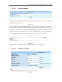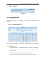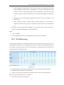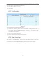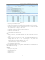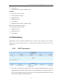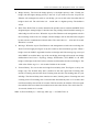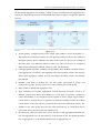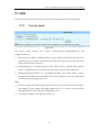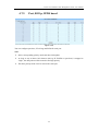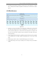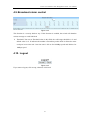
1
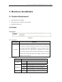
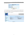
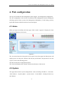
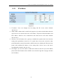
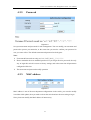
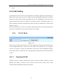
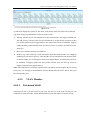
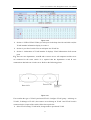
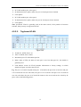
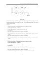
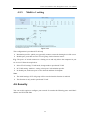
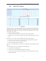
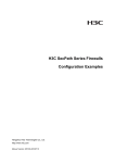
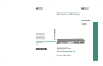
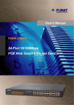
24 Port Fast Ethernet Web Management Switch User Manual V1.1 2010-05-31 24 Port Fast Ethernet Web Management Switch User Manual Package Contents The following items should be found in your package: ¾ 24 Port Fast Ethernet web management Switch ¾ Power Cord ¾ User Manual ¾ Rack-mount Bracket ¾ Screw ¾ Rubber feet Please make sure that the package contains the above items, if any of the listed items is damaged or missing, please contact with your distributor. 1 24 Port Fast Ethernet Web Management Switch User Manual Contents 1. 2. 3. INTRODUCTION .........................................................................................................................4 1.1. PRODUCT OVERVIEW ...............................................................................................................4 1.2. MAIN FEATURES ......................................................................................................................4 1.3. SUPPORTING STANDARD AND PROTOCOL .................................................................................4 1.4. WORKING ENVIRONMENT ........................................................................................................5 HARDWARE INSTALLATION...................................................................................................6 2.1. SYSTEM REQUIREMENT ...........................................................................................................6 2.2. PANEL ......................................................................................................................................6 2.3. HARDWARE INSTALLATION PROCEDURES ................................................................................7 LOGIN............................................................................................................................................8 3.1. 4. CONFIGURE COMPUTER............................................................................................................8 3.1.1. Windows 98/Me ..............................................................................................................8 3.1.2. Windows 2000 ................................................................................................................8 3.1.3. Windows XP ................................................................................................................. 11 3.1.4. Windows Vista ..............................................................................................................14 3.2. CHECKING PC’S IP AND CONNECTION WITH THE SWITCH ......................................................18 3.3. LOGIN ....................................................................................................................................19 WEB CONFIGURATION ..........................................................................................................21 4.1. HOME ....................................................................................................................................21 4.2. SYSTEM .................................................................................................................................21 4.2.1. IP address.....................................................................................................................22 4.2.2. Password ......................................................................................................................23 4.2.3. MAC address ................................................................................................................23 4.2.4. System update...............................................................................................................24 4.2.5. Statistics status .............................................................................................................24 4.2.6. Load default .................................................................................................................25 4.2.7. Backup & Recovery......................................................................................................25 4.2.8. Reboot ..........................................................................................................................26 4.3. PORT MANAGEMENT..............................................................................................................26 4.3.1. Port Configuration .......................................................................................................26 4.3.2. Port Mirroring..............................................................................................................27 4.3.3. Port Statistics ...............................................................................................................28 4.3.4. Band Restricting...........................................................................................................28 4.4. REDUNDANCY........................................................................................................................30 4.4.1. RST Parameters............................................................................................................30 4.4.2. RST Port .......................................................................................................................32 4.4.3. Link aggregation ..........................................................................................................32 4.5. VLAN SETTING .....................................................................................................................35 4.5.1. VLAN Mode..................................................................................................................35 2 24 Port Fast Ethernet Web Management Switch User Manual 4.5.1.1. 4.5.2. Port-based VLAN................................................................................................................... 36 4.5.2.2. Tag-based VLAN ................................................................................................................... 38 SECURITY ..............................................................................................................................40 Static MAC address ......................................................................................................41 4.6.2. TCP/UDP filter ............................................................................................................42 QOS ......................................................................................................................................43 4.7.1. Priority mode ...............................................................................................................43 4.7.2. Port, 802.1p, IP/DS based............................................................................................44 4.7.3. TCP/UDP port based ...................................................................................................45 4.8. MISCELLANEOUS ...................................................................................................................46 4.9. BROADCAST STORM CONTROL ...............................................................................................47 4.10. LOGOUT .................................................................................................................................47 CONSOLE CONFIGURATION ................................................................................................48 5.1. 6. Multi to 1 setting ..........................................................................................................40 4.6.1. 4.7. 5. VLAN Member..............................................................................................................36 4.5.2.1. 4.5.3. 4.6. Tag-based VLAN ................................................................................................................... 35 RESTORE TO DEFAULT ............................................................................................................48 FAQ ...............................................................................................................................................51 3 24 Port Fast Ethernet Web Management Switch User Manual 1. Introduction 1.1. Product Overview The 24 Port Fast Ethernet Web Management Switch fully complies with IEEE 802.3/802.3u Ethernet standards. It is a high-performance, multiple-purpose, high-security web management switch, which is mainly designed for large and medium enterprises. The 24 Port Fast Ethernet Web Management Switch provides 24 10/100Mbps UTP/STP RJ45 ports with auto-MDI/MDIX, 4.8Gbps switching fabric capacity. It also provides powerful web management page and firmware upgrades and more. It's wise to choose this web management switch. 1.2. Main Features ¾ 4.8Gbps switching fabric capacity ¾ Support link aggregation ¾ Support port-based VLAN and tag-base VLAN ¾ Support port mirroring ¾ Supports QOS ¾ Support MAC Binding ¾ Support TCP, UDP filtering ¾ Support web-based management ¾ Support firmware upgrade based on web ¾ Support parameter backup and recovery 1.3. Supporting Standard and Protocol ¾ IEEE 802.3 10Base-T ¾ IEEE 802.3u 100Base-TX ¾ IEEE 802.3x ¾ 10/100M full/half duplex ¾ IEEE 802.3ad ¾ IEEE802.1Q 4 24 Port Fast Ethernet Web Management Switch User Manual ¾ IEEE802.1D spanning tree protocol ¾ IGMP V1/V2 1.4. Working Environment Temperature ¾ 0° to 40° C (operating) ¾ -40° to 70° C (storage) Humidity ¾ 10% to 90 % non-condensing ¾ 5% to 90% non-condensing Power ¾ AC 100-240V /50-60Hz 5 24 Port Fast Ethernet Web Management Switch User Manual 2. Hardware Installation 2.1. System Requirement ¾ Standard personal computer ¾ Operating system: windows, Linux and etc. ¾ Standard web browser 2.2. Panel Front panel Figure 2-1 Port description: Description Function These ports support network speeds of 10Mbps or 100Mbps, and can operate in half and full duplex transfer modes. These ports also support automatic MDI/MDIX crossover detection, which 1X-24X gives the Switch true “plug and play” capabilities. Just connect any network cable between the Switch and the device, and The Switch will automatically detect the settings of the device and adjust itself accordingly. LED description: LED PWR LINK/ACT 10/100M Function On Power on Off Power off ON Corresponding port connection normal Flash Corresponding port data transmitting Off Corresponding port connection abnormal ON Corresponding port works in100Mbps 6 24 Port Fast Ethernet Web Management Switch User Manual Flash slowly Corresponding port works in 10Mbps Rear panel Figure 2-2 ¾ Console: console port ¾ Power: connect to Power cord 2.3. Hardware Installation Procedures Notice before setting up the 24 Port Fast Ethernet web management Switch The setup of the switch can be performed using the following steps: ¾ Install the switch in a fairly cool and dry place. See Working Environment for the acceptable operation temperature and humidity ranges ¾ Install the Switch in a site free from strong electromagnetic source, vibration, dust, and direct sunlight. ¾ Leave at least 10cm of space at the left and right hand side of the Switch for ventilation. ¾ Visually inspect the AC power jack and make sure that it is fully secured to the power adapter. ¾ Do not stack any device upon the Switch Installation ¾ Desktop or Shelf Installation When installing the Switch on a desktop or shelf, the rubber feet included with the device must be first attached. Attach these cushioning feet on the bottom at each corner of the device. Allow enough ventilation space between the device and the objects around it. ¾ Rack Installation The Switch can be mounted in an EIA standard size, which can be placed in a wiring closet with other equipment. To install, attach the mounting brackets on the switch’s front panel (one on each side) and secure them with the screws provided. Then, use the screws provided with the equipment rack to mount the Switch in the rack. 7 24 Port Fast Ethernet Web Management Switch User Manual 3. Login You can manage the 24 port Fast Ethernet web management switch via a web browser-based computer. The default IP address is 192.168.2.11, subnet mask is 255.255.255.0, so before you login the switch, please make sure the IP address in your computer and the switch are of the same network: 192.168.2.***(1<***<255, and ***is not 11). Please follow the steps below to configure your computer. 3.1. Configure computer 3.1.1. Windows 98/Me 1. Go to Start Æ Settings Æ Control Panel. 2. Find and double-click the Network icon. The Network dialog box appears. 3. Click the Configuration label and ensure that you have network card. 4. Select TCP/IP. If TCP/IP appears more than once, please select the item that has an arrow “Æ” pointing to the network card installed on your computer. DO NOT choose the instance of TCP/IP with the words “Dial Up Adapter” beside it. 5. Click Properties. The TCP/IP Properties dialog box appears. 6. Ensure use the following IP address is checked. Enter proper IP address and subnet mask 7. From the WINS Configuration dialog box, Ensure that Disable WINS Resolution is checked. 8. From the Gateway dialog box, remove all entries from the Installed gateways by selecting them and clicking Remove. 9. From the DNS Configuration dialog box, remove all entries from the DNS Server Search Order box by selecting them and clicking Remove. Remove all entries from the Domain Suffix Search Order box by selecting them and clicking Remove. Click Disable DNS. 10. Click OK, back to Network Configuration dialog box 11. Click OK, if prompted to restart, click YES. 3.1.2. Windows 2000 Please follow the steps below to setup your computer: 1. Go to Start Æ Settings Æ Control Panel 8 24 Port Fast Ethernet Web Management Switch User Manual Figure 3-1 2. Double click the icon Network and Dial-up Connections 3. Highlight the icon Local Area Connection, right click your mouse, and click Properties Figure 3-2 4. Highlight Internet Protocol (TCP/IP), and then press Properties button 9 24 Port Fast Ethernet Web Management Switch User Manual Figure 3-3 5. Choose use the following IP address automatically, enter proper IP address and then press OK to close the Internet Protocol (TCP/IP) Properties window. Please note that the IP address in your computer and the switch are of the same network: 192.168.2.***(1<***<255, and ***is not 11) 6. Press OK to close the Local Area Connection Properties window Figure 3-4 10 24 Port Fast Ethernet Web Management Switch User Manual 3.1.3. Windows XP Please follow the steps below to setup your computer: 1. Go to Start Æ Settings Æ Control Panel 2. Click Network and Internet Connections Figure 3-5 3. Click Network Connections Figure 3-6 4. Highlight the icon Local Area Connection, right click your mouse, and click Properties 11 24 Port Fast Ethernet Web Management Switch User Manual Figure 3-7 5. Highlight Internet Protocol (TCP/IP), and then press Properties button Figure 3-8 6. Choose use the following IP address automatically, enter proper IP address and then press OK to close the Internet Protocol (TCP/IP) Properties window. Please note that the IP address in your computer and the switch are of the same network: 192.168.2.***(1<***<255, and ***is not 11) 12 24 Port Fast Ethernet Web Management Switch User Manual Figure 3-9 7. Press OK to close the Local Area Connection Properties window Figure 3-10 13 24 Port Fast Ethernet Web Management Switch User Manual 3.1.4. Windows Vista Please follow the steps below to setup your computer: 1. Go to Start Æ Settings Æ Control Panel 2. Click Network and Sharing Center Figure 3-11 3. Click Manage Network Connections Figure 3-12 4. Highlight the icon Local Area Connection, right click your mouse, and click Properties 14 24 Port Fast Ethernet Web Management Switch User Manual Figure 3-13 5. Highlight Internet Protocol Version 4 (TCP/IP) and then press Properties button 15 24 Port Fast Ethernet Web Management Switch User Manual Figure 3-14 6. Choose use the following IP address automatically, enter proper IP address and then press OK to close the Internet Protocol (TCP/IP) Properties window. Please note that the IP address in your computer and the switch are of the same network: 192.168.2.***(1<***<255, and ***is not 11) 16 24 Port Fast Ethernet Web Management Switch User Manual Figure 3-15 7. Press OK to close the Local Area Connection Properties window 17 24 Port Fast Ethernet Web Management Switch User Manual Figure 3-16 3.2. Checking PC’s IP and Connection with the Switch After configuring the TCP/IP protocol, use the ping command to verify if the computer can communicate with the switch. To execute the ping command, open the DOS window and ping the IP address of the switch at the DOS prompt: ¾ For Windows 98/Me: Start -> Run. Type command and click OK. ¾ For Windows 2000/XP: Start -> Run. Type cmd and click OK. At the DOS prompt, type the following command: If the Command window returns something similar to the following: C:\Documents and Settings\admin>ping 192.168.2.11 Pinging 192.168.2.11 with 32 bytes of data: Reply from 192.168.2.11: bytes=32 time=1ms TTL=64 Reply from 192.168.2.11: bytes=32 time=1ms TTL=64 Reply from 192.168.2.11: bytes=32 time=1ms TTL=64 Reply from 192.168.2.11: bytes=32 time=1ms TTL=64 18 24 Port Fast Ethernet Web Management Switch User Manual Ping statistics for 192.168.2.11: Packets: Sent = 4, Received = 4, Lost = 0 (0% loss), Approximate round trip times in milli-seconds: Minimum = 1ms, Maximum = 1ms, Average = 1ms Then the connection between the switch and your computer has been successfully established. If the computer fails to connect to the switch, the Command window will return the following: C:\Documents and Settings\admin>ping 192.168.2.11 Pinging 192.168.2.11 with 32 bytes of data: Request timed out. Request timed out. Request timed out. Request timed out. Ping statistics for 192.168.2.11: Packets: Sent = 4, Received = 0, Lost = 4 (100% loss), Verify your computer's network settings are correct and check the cable connection between the switch and the computer. 3.3. Login 1. Startup Internet Explorer and enter http://192.168.2.11, then press Enter Figure 3-17 2. You will enter the user name and password and then click OK. The default user name is 19 24 Port Fast Ethernet Web Management Switch User Manual guest, password is guest, too. Figure 3-18 3. After successful login, you will be able to see the switch’s web-based configuration utility (refer to the following picture). In the home page of the switch, the left navigation bar shows the main options to configure the system. In the right navigation screen is the summary of system status for viewing the configurations. Figure 3-19 20 24 Port Fast Ethernet Web Management Switch User Manual 4. Web configuration The 24 port Fast Ethernet web management switch support web management configuration. The web configuration of the 24 Port Fast Ethernet Web Management Switch including the following options: Home, System, Port Management, Redundancy, VLAN Setting, Security, QOS, Miscellaneous, Broadcast Storm Control and logout 4.1. Home When you login successfully, the home page of this switch is appears. It displays the basic and advanced features of the switch Figure 4-1 The 1st section shows the front panel of the switch. In the front panel, the linked ports will display green; as to the ports, which are link off, they will be dark. The port that we use now is port 6, refer to the following picture The 2nd section shows configuration options The 3rd section displays basic features and advanced features of this switch 4.2. System This page Show the basic system configuration’s wizard, including “IP address”, “Password”, “MAC address”, “System update”, “System status”, “Load default”, “Backup & Recovery” and “Reboot” 21 24 Port Fast Ethernet Web Management Switch User Manual 4.2.1. IP address Figure 4-2 ¾ IP address: Users can configure the IP settings and fill in new values. Default: 192.168.2.11 ¾ Subnet Mask: Subnet mask is made for the purpose to get more network address because any IP device in a network must own its IP address, composed of Network address and Host address, otherwise can’t communicate with other devices each other. Default: 255.255.255.0 ¾ Gateway: Set an IP address for a gateway to handle those packets that do not meet the routing rules predefined in the device. If a packet does not meet the criteria for other pre-defined path, it must be forwarded to a default router on a default path. This means any packet with undefined IP address in the routing table will be sent to this device unconditionally. Default: 192.168.2.254 ¾ IP configure: you can select Static or DHCP, the default is static IP. If you select DHCP, please obtain the IP address from a DHCP server and then login the web page with this new IP address 22 24 Port Fast Ethernet Web Management Switch User Manual 4.2.2. Password Figure 4-3 Set system username and password for web management. You can modify your username and password to protect your networks, at the same time you need to confirm your password in case you enter a false. The default username and password are both guest Note: ¾ Username & Password can only use "a-z","A-Z","0-9","_","+","-","=" ¾ Please remember the new modified password. If you forget the new password, the only way to login this switch is restore to factory settings, and at the same time all parameters configured will be lost ¾ This username and password modify operation 4.2.3. MAC address Figure 4-4 MAC address is one of the most important configurations in the switch, you can also modify it and then click update, then you need to reboot the switch and use the new setting to login Note: please not modify the MAC address if unnecessary 23 24 Port Fast Ethernet Web Management Switch User Manual 4.2.4. System update Figure 4-5 You can update the switch through this function. If the firmware is old, please enter password and reconfirm it and then click update. In the pop-up window, click OK button, the flash erase page appears, wait for about 10 seconds, in the update page (Figure 4-6), click browser button and select a File to upgrade, after you have selected the appropriate file, click Upgrade button to execute upgrade procedure. After the update finish, the switch restarts automatically Figure 4-6 Note: please do not cut off the power supply during the process of upgrading 4.2.5. Statistics status Figure 4-7 24 24 Port Fast Ethernet Web Management Switch User Manual You can customize your switch, including comment, contact, location and idle time security in this item ¾ Number of ports: display the number of ports in this switch ¾ Comment: user-define device comment, max 15 character ¾ Contact: the contact information of system manager, max 15 character ¾ Location: the location of the device, max 15 character ¾ Idle time security: time when the switch goes to standby mode, max time 1800 seconds ¾ System version: display software firmware version of the switch Note: comment can only use “a-z”, “A-Z”, “-”, “+”, “_”, “0-9” 4.2.6. Load default Figure 4-8 Click load, this switch will restore to default setting automatically Note: All parameters will lost after click this button, make sure you have backup all settings before click load button 4.2.7. Backup & Recovery Figure 4-9 This allows you to backup and comeback the system’s parameters 25 24 Port Fast Ethernet Web Management Switch User Manual 4.2.8. Reboot Figure 4-10 Reboot your system 4.3. Port Management Port management includes port configuration, port mirroring, port statistics and band restricting 4.3.1. Port Configuration Figure 4-11 You can configure Tx/Rx ability, auto negotiation, speed, duplex, pause, backpressure and address learning for each port ¾ Port configuration Tx/Rx ability: enable or disable transmit and receive ability, if you disable Tx/Rx ability for one port, the selected port isn’t able to transmit and receive packets. The default is enable Auto negotiation: enable or disable auto negotiation. The default is auto Speed: you can configure speed (10/100M) for each port Duplex: configure full and half duplex for each port. The default is full duplex 26 24 Port Fast Ethernet Web Management Switch User Manual Pause: enable or disable pause. This function requires connecting devices must support IEEE802.3 and transfer in full duplex. It is used to synchronize the rate between receiver and transmitter. When the forward buffer is full, the switch will send pause frame to inform transmit device to stop data transmitting. The default is on Backpressure: the switch support backpressure when it works in half duplex. The default is on Addr. Learning: enable or disable address learning function. If the function is disabled, the device in this port can’t communicate with other devices. The default is on ¾ Select port: select port that need configure, you can either single or multi select ports. When you finish the configuration, click update button Note: ¾ ---is not configure ¾ False configuration result in corresponding port work normal or disabled 4.3.2. Port Mirroring Port mirroring supplies port sniffer function, which can copy data from source port to destination port. It allows user to configure mirror ports to monitor data of guarded ports, the user analyses monitored data to know the information of guarded ports and then achieve network detection, monitor and so on Figure 4-12 ¾ Destination port: monitor port, generally connect to network monitoring equipment ¾ Monitored packets: the direction of message ¾ Source port: port that are monitored, generally connect to other network equipment E.g. Copy the message of port 14, 15 to port 1, 2 ¾ Select port 1 and 2 in destination port 27 24 Port Fast Ethernet Web Management Switch User Manual ¾ Select egress& ingress in the monitored packets ¾ Select port 14 and 15 in source port ¾ Click update 4.3.3. Port Statistics Figure 4-13 This item displays packets information for each port. ¾ Counter mode selection: you can select counter mode, including transmit packet & receive packet, collision count & transmit packet, drop packet & receive packet or CRC error packet & receive packet ¾ Reset: reset all statistics information ¾ Refresh: refresh statistics information of current port 4.3.4. Band Restricting This function is one of the featuring functions of this switch, through which you can restrict TX and RX rate for each port. Reasonable bandwidth can optimize network structure. 28 24 Port Fast Ethernet Web Management Switch User Manual Figure 4-14 ¾ Port No.: port for bandwidth restrict ¾ Tx/Rx rate: select transmit/receive rate for each port, the number is 0-255, 0 is no limit ¾ Speed base: rata-limiting base of the switch, including two, one is low, the other is high. The speed base of low is 32Kbps, the latter is 256 ¾ Load default: configure rate-limiting parameters of all port is 0 ¾ TX/RX rate: current TX/RX rate ¾ Link speed: the actual negotiation rate Note: ¾ When you select low, Actual Tx/Rx bandwidth =Rate value×32kbps. The rate value is 1~255 ¾ When you select high, if the link speed is 100M, Actual Tx/Rx bandwidth=Rate value× 256Kbps and the rate value is 1~255. If the link speed is 10M, Actual Tx/Rx bandwidth=Rate value×256Kbps and the rate value is 1~39. The connection rate is --- if the port is not connected ¾ The minimum rate limit is 32Kbps E.g1. Configure the TX/RX rate of port1-port10 is 256Kbps. There are two methods, the first select low, the other select high Method1: ¾ Select port 1 in the port No. ¾ Select speed base is low ¾ Input TX rate is 8 ¾ Input RX rate is 8 29 24 Port Fast Ethernet Web Management Switch User Manual ¾ Click update ¾ Repeat the above steps for another 9 ports Method2: ¾ Select port 1 in the port No. ¾ Select speed base is high ¾ Input TX rate is 1 ¾ Input RX rate is 1 ¾ Click update ¾ Repeat the above steps for another 9 ports E.g2. Cancel band restrict of port3 ¾ Select port 3 in the port No. ¾ Input TX rate is 0 ¾ Input RX rate is 0 ¾ Click update 4.4. Redundancy Redundancy can avoid network meltdown due to network cycle effectively, thus enhance stability and reduce network failure. It includes RST Parameters, RST Port and Link aggregation 4.4.1. RST Parameters Figure 4-15 ¾ STP mode: Two options are offered for the user’s choosing STP algorithm. One is RSTP (Rapid Spanning Tree Mode) and the other is STP (Spanning Tree Compatible Mode). If STP is chosen, RSTP will run as a legacy STP. The switch supports RSTP (802.1w) which is backward compatible with STP (802.1d) 30 24 Port Fast Ethernet Web Management Switch User Manual ¾ Bridge Priority: The lower the bridge priority is, the higher priority it has. Usually, the bridge with the highest bridge priority is the root. If you want to have the 24 port Fast Ethernet web management switch as root bridge, you can set this value lower than that of bridge in the LAN. The valid value is 0 ~ 61440 and 0 is highest priority. The default is 32768 ¾ Hello Time: Hello Time is used to determine the periodic time to send normal BPDU from designated ports among bridges. It decides how long a bridge should send this message to other bridge to tell I am alive. When the 24 port Fast Ethernet web management switch is the root bridge of the LAN, for example, all other bridges will use the hello time assigned by this switch to communicate with each other. The valid value is 1 ~ 10 in unit of second. Default is 2 seconds ¾ Max Age: When the 24 port Fast Ethernet web management switch is the root bridge, the whole LAN will apply this figure set by this switch as their maximum age time. When a bridge received a BPDU originated from the root bridge and if the message age conveyed in the BPDU exceeds the Max. Age of the root bridge, the bridge will treat the root bridge malfunctioned and issue a Topology Change Notification (TCN) BPDU to all other bridges. All bridges in the LAN will re-calculate and determine who the root bridge is. The valid value of Max. Age is 6 ~ 40 seconds. Default is 20 seconds ¾ Forward Delay: You can set the root bridge forward delay time. This figure is set by root bridge only. The forward delay time is defined as the time spent from Listening state moved to Learning state and also from Learning state moved to Forwarding state of a port in bridge. The forward delay time contains two states, listening state to Learning state and Learning state to Forwarding state. It assumes that forward delay time is 15 seconds, then total forward delay time will be 30 seconds. This has much to do with the STP convergent time which will be more than 30 seconds because some other factors. The valid value is 4 ~ 30 seconds, default is 15 seconds Note: 2*(Forward Delay-1)>= Max Age, Max Age >= 2*(Hello Time+1) 31 24 Port Fast Ethernet Web Management Switch User Manual 4.4.2. RST Port Figure 4-16 Enter priority and RPC for each port ¾ Priority: it indicates the priority of designated port. The priority can be used to determine the port to choose when there are two ports connect in the same LAN ¾ RPC: the number that RPC can select is from 1 to 200000000. The smaller the number is, the more possible the corresponding port be selected to transmit data packets. 0 is auto ¾ Status: shows the current STP status of each port. Disable: indicates port link is disconnect Blocking: port is blocked, can’t transmit or learn MAC address Listening: port is in listening mode, can’t transmit and learn MAC address Learning: port is in learning mode, can’t transmit but can learn new MAC address Forwarding: port is in transmitting mode, can transmit and learn new MAC address ¾ Designated bridge: indicates MAC address and priority of designated bridge ¾ Designated port: indicates MAC address and priority of selected port from designated bridge Note: if you want to use this function, you only need to select RSTP mode. The switch will transmit BPDU and figure with other switches automatically, there is no need to configure generally 4.4.3. Link aggregation The Link Aggregation Configuration is used to configure the settings of Link Aggregation. You can bundle more than one port to be a single logical port, thus the logical port aggregates the bandwidth of these ports. This means you can apply your current Ethernet equipments to build 32 24 Port Fast Ethernet Web Management Switch User Manual the bandwidth aggregation. For example, if there are three Fast Ethernet ports aggregated in a logical port, then this logical port has bandwidth three times as high as a single Fast Ethernet port has Figure 4-17 ¾ System priority: configure priority of the switch, enter number 1-65535, the default is 1. The number shows the main counter of LACP protocol. When two devices are connected, the higher priority device undertakes the main count. If the two devices are configured the same, there is no difference whoever counts, but if the two devices are configured different, the result maybe different whoever counts. The default is 1 ¾ Link aggregation algorithm: including two algorithms: MAC Src&Dst and MAC Source. Link aggregation is counted by this algorithm. The value represent, when a data message want to pass aggregation channel, the CPU must figure out which port the data message pass through. ¾ Member: port1-port8 is divided into two link group, port1-port4 is group1 and port5-port8 is group2. You may select one or some of these ports as link group ¾ State: enable or disable link aggregation state ¾ Type: including LACP (Link Aggregation Control Protocol) and static. LACP is an Ethernet protocol that allows the bundling of several ports. It provides a method to control the bundling of several physical ports together to form a single logical channel. LACP allows a network device to negotiate an automatic bundling of links by sending LACP packets to the peer (directly connected device that also implements LACP). The members in the same group must have the same operation key in LACP mode, but in static mode, active ports have the same operation key ¾ Operation key: enter a key between 1-65535. This key is link aggregation identifier, the two link aggregation can’t be the same key, or the function is fail. The default operation key of aggregation1 is 1, the default operation key of aggregation2 is 2 33 24 Port Fast Ethernet Web Management Switch User Manual ¾ Time out: select long time out or short time out ¾ Activity: select passive and active. Active mode transmit protocol message. In passive mode, only the opposite side is active mode that transmit message. The default is active E.g 1. link aggregation between two devices, using static mode. The 1 and 2 port of switch A and 1 and 2 port of switch B link aggregation In switch A, ¾ Use the default values when select system priority and link aggregation algorithm and then click submit ¾ Select port 1 and port 2 as link group 1 ¾ State is configured to enable ¾ Select static in type ¾ Configure operation key is 3. The key of the two switches are different is OK ¾ Click submit ¾ Repeat the above steps of switch A in switch B E.g 2. link aggregation between two devices, using LACP mode. The 1 and 2 port of switch A and 1 and 2 port of switch B link aggregation In switch A, ¾ Use the default values when select system priority or use a different one from switch B ¾ Use the default values when select link aggregation algorithm ¾ Select port 1 and port 2 as link group 1 ¾ State is configured to enable ¾ Select LACP in type ¾ Configure operation key of the two switches are different is OK ¾ Select long time out in time out ¾ Select active in activity ¾ Click submit ¾ Repeat the above steps of switch A in switch B Note: ¾ The switch support 2 link aggregation group, 4 ports each group ¾ The link aggregation group 1 can only be port 1-4, group 2 can only be port 5-8, the other ports can’t be in link aggregation groups ¾ Link aggregation can only be used in full duplex Ethernet network ¾ All links in the link group must work in the same rate ¾ If you enable LACP on some specified port and their link partners are normal port without LACP, these specified ports can’t transmit packet to/ receive packet from the link 34 24 Port Fast Ethernet Web Management Switch User Manual partner 4.5. VLAN Setting VLAN divides the devices of the LAN logically into different segments (not physically) to fulfill virtual work group. In order to setup secure and independent broadcast or multicast domain, the switch can be divided into multiple VLAN. The establishment of VLAN restricts spread extension and reduces the influence of broadcast packets. All Ethernet packets, e.g. unicast, multicast, broadcast and unknown packets can only be transmitted in VLAN, which improves security The other advantage of VLAN is it can change topological structure of network, but physical movement of workstation or line link of network are not needed 4.5.1. VLAN Mode Figure 4-18 This option can change VLAN mode. The switch support tag VLAN and port-based VLAN. VLAN configuration divide LAN into several logical LAN, depends on you. Configure correctly can improve security and performance and reduce VLAN management greatly. Click change mode, VLAN mode can be changed between tag-based VLAN and port-based VLAN. 4.5.1.1. Tag-based VLAN Tag-based VLAN is usually called 802.1Q VLAN. It divides network connection of LAN logically and supplies connection service between several VLAN, which make VLAN connection between different manufacture possible. 35 24 Port Fast Ethernet Web Management Switch User Manual Figure 4-19 VLAN mode display the current VLAN mode, click change mode, the mode can be changed Tag mode display tag information of all ports in the switch ¾ Add tag: add 802.1Q VLAN information to data frame header. The tagging enabled port will add priority, VID and other VLAN information to all data frame in and out of this port. If data packet has been tagged before, this data packet will not be modified. Tagging enable the data packet transmit form one 802.1Q switch to another switch that has the same type ¾ Don’t care: transmit message in normal way ¾ Remove tag: remove 802.1Q VLAN information from data frame header. The untagging enabled port will remove priority, VID and other VLAN information from all data frame in and out of this port. If data packet hasn’t been tagged before, this data packet will not be modified. Untagging enable the data packet transmit form one 802.1Q switch to another switch that not support 802.1Q Note: If the link partner is a network interface card, it probably cannot recognize the VLAN tag. In this case, it is strongly recommended the network administrator to remove the VLAN tag of the corresponding port 4.5.2. 4.5.2.1. VLAN Member Port-based VLAN Port-based VLAN is VLAN based on port, only the devices in the same VLAN port can communicate with each other, which shield broadcast storm and improve network security. 36 24 Port Fast Ethernet Web Management Switch User Manual Figure 4-20 ¾ Section 1: PVID of VLAN. When you select port in the drop down list and click read, the VLAN member information display in section 3 ¾ Section 2: port list of switch. You can add ports into VLAN list ¾ Section 3: information of VLAN member. It displays VLAN information of all current ports E.g. There are two departments, A and B and a resource server. All computers and the server are connected in the same switch. It is required that the department A and B can’t communicate but both can visit the server. Refer to the following picture Figure 4-21 First confirm the type of VLAN--port-based VLAN. Configure VLAN group—A belongs to VLAN 1, B belongs to VLAN 2, the resource server belongs to VLAN 1 and VLAN 2 and is connected to the 24 port of the switch, follow the steps below ¾ Select VLAN setting- VLAN mode, change mode to port-based VLAN 37 24 Port Fast Ethernet Web Management Switch User Manual ¾ In VLAN member-port, select port 1 ¾ In destination select option, make sure port 1-10 and port 24 are checked ¾ Click update ¾ In VLAN member-port, select port 2 ¾ In destination select option, make sure port 11-20 and port 24 are checked ¾ Click update Note: port-based VLAN is generally used in the same switch, if the partition is between switches, then you may use tag-based VLAN 4.5.2.2. Tag-based VLAN Figure 4-22 ¾ VLAN No.: PVID, from 1-24 ¾ VID: VLAN ID, from 1-4096 ¾ Destination port: VLAN member port list ¾ Index: index of VID, the index of each port is one less than port No., the default is generally used ¾ Load default: restore all VLAN member information to factory settings, in which situation all ports are in the same VLAN E.g. The port 1 of switch A uplink with port 1 of switch B, the port 2-10 of switch A and port 2-10 of switch B can visit each other, the port 11-23 of switch A and port 11-23 of switch B can visit each other, the port 24 of switch B connect to the server and can be visited by all ports, refer to the following picture: 38 24 Port Fast Ethernet Web Management Switch User Manual Figure 4-23 First confirm the type of VLAN--tag-based VLAN. Configure VLAN group—port 2-10 belong to VLAN 3, port 11-23 belong to VLAN 4, the server belongs to VLAN 3 and VLAN 4, follow the steps below Switch B: ¾ Select VLAN setting- VLAN mode, change mode to tag-based VLAN ¾ Change tag mode of port 1 is add tag ¾ Change tag mode of port 2-23 and port 24 is remove tag ¾ Click update ¾ In VLAN member-port, select port 3 and enter 3 in VID text ¾ In destination select option, make sure port 1-10 and port 24 are checked and click update ¾ In VLAN member-port, select port 4 and enter 4 in VID text ¾ In destination select option, make sure port 1, 11-23 and port 24 are checked and click update Switch A: ¾ Select VLAN setting- VLAN mode, change mode to tag-based VLAN ¾ Change tag mode of port 1 is add tag ¾ Change tag mode of port 2-23 is remove tag ¾ Click update ¾ In VLAN member-port, select port 3 and enter 3 in VID text ¾ In destination select option, make sure port 1-10 are checked and click update ¾ In VLAN member-port, select port 4 and enter 4 in VID text ¾ In destination select option, make sure port 11-23 are checked and click update 39 24 Port Fast Ethernet Web Management Switch User Manual 4.5.3. Multi to 1 setting Figure 4-24 This configuration is port-based VLAN only ¾ Destination port No.: public port, generally connect to network sharing device like server ¾ Disable port: ports that are not in VLAN group, checked means remove E.g.: The port 1 of switch connects to a sharing server and only allows the computers in port 10-24 visit. Follow the steps below: ¾ Select VLAN setting- VLAN mode, change mode to port-based VLAN ¾ In VLAN setting- multi to 1 setting, select port 1 in destination port No. ¾ In disable port, make sure port 2-9 are checked and then click update Note: ¾ The initial settings of VLAN group will be erased when this function is enabled ¾ This function is only used in port-based VLAN 4.6. Security You can use this option to configure your network. It contains the following parts: static MAC address and TCP/UDP filter 40 24 Port Fast Ethernet Web Management Switch User Manual 4.6.1. Static MAC address Figure 4-25 Static MAC address is a security technology based on port. Generally, MAC address table is established by source address learning, but the network administrator can add special MAC address into MAC address table, and make it binding with corresponding port of switch, which improve port security. ¾ Port No.: display current port no. ¾ Select port: select one port that you want to achieve MAC address binding ¾ Binding: you may select enable or disable to enable or disable binding status for each port E.g.: There is one PC in port 1 that needs binding, please follow the steps below: ¾ Select port 3 in select port option in security-static MAC address and then click update ¾ Enter 00-10-10-10-10-10 in MAC address binding list ¾ Select enable binding and then click update Select port 3 in select port option, click read to view whether MAC address binding is enabled Note: ¾ The binding device can only communicate in the binding port ¾ Each port can only binding 5 MAC ¾ The same device can’t be binding and filtering at the same time ¾ If you enable the MAC address binding function, the address leaning function will be disabled automatically. 41 24 Port Fast Ethernet Web Management Switch User Manual 4.6.2. TCP/UDP filter Figure 4-26 This function is also a basic security defense measure ¾ Function enable: select enable or disable. It is the first step before using TCP/UDP filter ¾ Port filtering rule: the outgoing packet with selected protocol will be either forwarded or dropped at secure WAN port as the figure shown below. Negative means the selected protocol will be dropped and other protocols will be forwarded. Positive means the selected protocol will be forwarded and other protocol will be dropped. ¾ Protocol: The protocol item supplies several protocols, including FTP, TELNET, HTTPS, HTTP etc. Of course you can define protocols yourself ¾ Secure WAN port: select one or more protocol to drop or forward for selected port. The port means the port connected between router and switch E.g. The router is in port 1 of the switch, and it forbid all PCs’ FTP and TELNET application that connected to it, the other applications are allowed ¾ Enable security—TCP/UDP filter ¾ Select negative in the port filtering rule or use the default value directly ¾ Select FTP and TELNET in the protocol ¾ Select port 1 in the secure WAN port and click update Note: user-defined template will be configured in QOS option 42 24 Port Fast Ethernet Web Management Switch User Manual 4.7. QOS It contains three parts: priority mode, port, 802.1p, IP/DS based and TCP/UDP port based 4.7.1. Priority mode Figure 4-27 The priority mode includes three modes: fist-in-first-out, all-high-before-low and weight-round-robin ¾ First-in-first-out (FIFO): traditional priority mode, which follow first-in-first-out rules, bit enter from one side and out from the other side in the same order. It will be saved in FIFO when the frame is received. ¾ All-high-before-low: absolute priority mode, which always transmits high priority packets, if high priority has no packets, the low priority packets can be transmitted. ¾ Weight-round-robin (WRR): it is a scheduling discipline. The switch support 8 queue, queues are serviced based on the weight. There are two options, one is low weight, from 1-8, the other is high weight, from 1-8 Note: ¾ The "low weight" and "high weight" means the ratio of the packet in the transmit queue. For example, if "low weight" and "high weight" are set to "3" and "5", the ratio of the transmit packet for the low priority to high priority is 3/5 ¾ The large the number is, the higher the priority is 43 24 Port Fast Ethernet Web Management Switch User Manual 4.7.2. Port, 802.1p, IP/DS based Figure 4-28 You can configure port base, VLAN tag and IP/DS for each port. Note: ¾ Select corresponding priority mode and then click update ¾ As long as any of three COS schemes (802.1q, IP TOS/DS or port base) is mapped to “high”, the data packet will be treated as the high priority ¾ The three priority mode can’t be used in the same port 44 24 Port Fast Ethernet Web Management Switch User Manual 4.7.3. TCP/UDP port based Figure 4-29 The Class of Service for TCP/UDP port number allows the network administrator to assign the specific application to a priority queue. ¾ F-I-F-O: The incoming packet will be forwarded in first-in-first-out scheme. ¾ Discard: The incoming packet will be discarded at the source port. ¾ High: The incoming packet will be forwarded with the high priority. ¾ Low: The incoming packet will be forwarded with the Low priority Figure 4-30 ¾ Port number: input TCP/UDP port, the number is 0-65535 ¾ Mask: the mask defines which bit is ignored within the IP address bit 0-bit 7. If UDP/TCP port = 65535 and mask = 5, this means 65530, 65531, 65534 and 65535 are all taken into account. UDP/TCP port =65535 and mask=0, this means only 65535 is taken into account. 45 24 Port Fast Ethernet Web Management Switch User Manual ¾ TCP/UDP port QoS function: including override and not override. When the “override” item is selected, the Port-based, Tag-based, IP TOS-based, CoS listed above will be ignored. 4.8. Miscellaneous Figure 4-31 ¾ Aging time: you may select disable or select aging time, including 200, 400, 600 and 800. The output queue aging function allows the administrator to select the aging time of a packet stored in the output queue. A packet stored in the output queue for a long time will lower the free packet buffer, resulting in the poor utilization of the buffer and the poor switch performance ¾ VLAN striding: When this function is enabled, the switch will forward a uni-cast packet to the destination port. No matter whether the destination port is in the same VLAN group ¾ IGMP snooping V1&V2: enable or disable IGMP Snooping V1 & V2 function ¾ VLAN uplink setting: select one port as uplink port. It is mainly used to prevent address conflict. 46 24 Port Fast Ethernet Web Management Switch User Manual 4.9. Broadcast storm control Figure 4-32 This function is a security defense way. If this function is enabled, the switch will abandon useless message to avoid link block ¾ Threshold: You can set Threshold value in this field, the valid range should be 1-63 and default value is 63. It indicates the number of broadcast packet which is allowed to enter each port in one time unit. One time unit is 500 us for 100Mbps speed and 5000 us for 10Mbps speed 4.10. Logout Figure 4-33 If you want to logout, click accept, otherwise click back 47 24 Port Fast Ethernet Web Management Switch User Manual 5. Console configuration There are also other ways to configure the 24 port Fast Ethernet web management switch, for example: Hyper Terminal of Microsoft Windows. You can use this method to manage this device easily. Please note that the console port is in rear panel of the switch Note: This method can only be used to restore the switch to default 5.1. Restore to default ¾ Connect the PC and serial of the switch, click Start- All Programs- AccessoriesCommunications- Hyper Terminal, open the Hyper Terminal Figure 5-1 ¾ Enter name of the new connection, click OK 48 24 Port Fast Ethernet Web Management Switch User Manual Figure 5-2 ¾ Select using com, click OK Figure 5-3 ¾ Refer to the following picture to configure port settings, click OK 49 24 Port Fast Ethernet Web Management Switch User Manual Figure 5-4 ¾ Power on the 24 Port Fast Ethernet web management switch, press D on the keyboard all the time until the following picture appears. The switch will restore to default settings automatically Figure 5-5 50 24 Port Fast Ethernet Web Management Switch User Manual 6. FAQ 1. NO Link LED Condition The possible causes for a no link LED status are as follows: ¾ The attached device is not powered on ¾ The cable may not be the correct type or is faulty ¾ The installed building premise cable is faulty ¾ The port may be faulty 2. Computer A can connect to Computer B, but cannot connect to Computer C through the Managed Switch. ¾ The network device of Computer C may fail to work. Please check the link/act status of Computer C on the LED indicator. Try another network device on this connection. ¾ The network configuration of Computer C may be something wrong. Please verify the network configuration on Computer C. 3. The uplink connection function fails to work. ¾ The connection ports on another must be connection ports. Please check if connection ports are used on that Managed Switch. ¾ Please check the uplink setup of the Managed Switch to verify the uplink function is enabled. 4. The console interface can’t appear on the console port connection. ¾ The COM port default parameters are [Baud Rate: 38400, Data Bits: 8, Parity Bits: None, Stop Bit:1, Flow Control: None]. Please check the COM port property in the terminal program. And if the parameters are changed, please set the COM configuration to the new setting. ¾ Check the RS-232 cable is connected well on the console port of the Managed Switch and COM port of PC. ¾ Check if the COM of the PC is enabled. 5. How to configure the Managed Switch? ¾ The “Hyperterm” is the terminal program in Win95/98/NT. Users can also use any other terminal programs in Linux/Unix to configure the Managed Switch. Please refer to the user manual of that terminal program. But the COM port parameters (baud rate/ data bits/ parity bits/ flow control) must be the same as the setting of the console port of the Managed Switch 51