1
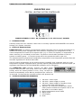
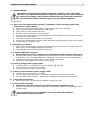
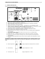
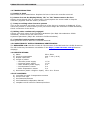
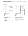
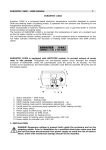
EUROSTER 11M USER MANUAL 1 EUROSTER 11M CENTRAL HEATING SYSTEM CONTROLLER MANUFACTURER: P.H.P.U. AS, Polanka 8a/3, 61-131 Poznań, POLAND 1. INTRODUCTION Carefully study this user manual to learn how to correctly operate the EUROSTER 11M central heating (CH) system controller. 2. FIELD OF APPLICATION EUROSTER 11M is a modern microprocessor-based controller used to control temperature by means of a mixing valve equipped with limit switches. Depending on configuration it may control temperature of water at CH system inlet (e.g. in a floor CH system) or temperature of water returning (re-circulated) to the boiler. The device controls also operation of the CH system circulation pump – it turns the pump off for the period the boiler is put out. The implemented PI (proportional-integration) temperature control algorithm provides fast and accurate regulation for various heat loads. Used to control temperature at CH system inlet the controller may cooperate with any room temperature regulator equipped with a normally-opened (NO) potential-free contact output (all regulators manufactured by the EUROSTER company are so equipped). The EUROSTER 11M controller features the ANTY STOP function that prevents idle pump rotors and valves against seizing. Once the heating season is over, every 14 days the function automatically turns ON the pumps and the valves for 30 seconds. To that end the controller must be left powered up. 3. VISIBLE CONTROLLER ELEMENTS 1. 230 VAC~ mains input 2. 230 VAC~ power supply to pump 3. 230 VAC~ power supply to actuator of the mixing valve with limit switches 4. Input for the controlled temperature sensor cable (sensor located at CH system inlet or at the boiler re-circulation input) 5. Boiler temperature sensor cable 6. Mains switch 7. LCD display 8. Knob EUROSTER 11M USER MANUAL 2 4. INSTALLATION Hazardous voltages may be present inside the controller and on its cables. Therefore it is expressly forbidden to install the device prior to disconnecting its mains power supply. Only qualified technicians may install the controller. Do not install any devices showing signs of any mechanical damage. The procedure: a) Hook up room temperature regulator (optionally, only in the CH system inlet temperature control mode): make sure that mains power supply is disconnected from the controller remove 5 bolts that fix controller box back panel gently lever up and remove the knob carefully remove controller box front panel cut out a new opening for room temperature regulator cable in the box bottom next to openings for sensor cables remove 2 fixing screws and remove the jumper mount room temperature regulator cable and screw its two wires in place of the jumper re-assemble the controller box. b) Mount the controller: using a pair of supplied nylon nail-it fasteners (anchors) mount the controller box on a wall (or any other suitable supporting structure) using fasteners fix controller cables to the wall. c) Install temperature sensors: do not immerse sensors in liquids nor install them within stream of flue gases install the CH system inlet temperature sensor at the boiler point specially designed for that purpose or on an unshielded boiler outlet pipe (as close to the boiler as possible) install the other temperature sensor at the mixing valve output using hose clips tighten the sensors to their pipes. d) Hook up pump power supply cable: connect yellow (or yellow-green) PE wire with the connect blue wire with the N terminal connect brown wire with the L terminal. terminal e) Hook up valve actuator power supply cable: connect blue wire with the N terminal connect brown wire with the L – zamykanie, obniżanie temperatury terminal connect black wire with the L – otwieranie, podwyższanie temperatury terminal. f) Verify the connections: check up all cable connections and tighten terminal box lids. g) Hook up the controller: make sure controller cables are protected against incidental cut off plug the controller power supply cable into a 230V/50Hz mains socket equipped with a grounding pin. The controller must not be installed in a place where the ambient temperature may exceed 40ºC. EUROSTER 11M USER MANUAL 3 5. CONTROLLER DISPLAY Elements of the controller display: 1. 2. 3. 4. 5. 6. Name of the controlled parameter (displayed while set point value is browsed/set) Heat source (boiler) temperature sensor icon Manual operation mode (icon lit while the temperature is manually controlled) Alarm (icon blinks in case of an alarm) State of the heat source (boiler) furnace – animated icon, see description below State of the room temperature regulator input (only in the CH inlet temperature control mode; symbol lit while the regulator is demanding more heat) 7. Heat source (boiler) temperature / other displayed parameter value 8. Actual value of the controlled temperature / displayed parameter number 9. Re-circulated water temperature control mode icon 10. Pump icon lit while the pump is running (only in the re-circulated water temperature control mode) 11. Re-circulated water temperature sensor icon (only in the re-circulated water temperature control mode) 12. Mixing valve icon – individual segments are lit while valve actuator is activated 13. Pump icon lit while the pump is running (only in the CH system inlet temperature control mode) 14. CH system inlet temperature sensor (only in the CH system inlet temperature control mode) Animated icon that visually presents state of the heat source (boiler) furnace is for information purposes only, it does not influence operation of the controller in any way. Normal operation: <-> supply temperature between 25ºC and 90ºC Overheating: <-> supply temperature > 90ºC Furnace put out: supply temperature < 25ºC EUROSTER 11M USER MANUAL 4 6. TURNING THE CONTROLLER ON Turn the controller mains switch (Błąd: Nie znaleziono źródła odwołania in section 3) into the “I” position. Device firmware version No. and compilation date are sequentially displayed for 2 s. “AS” letters are blinking on the display while the ANTY STOP functions turns on the mixing valve, then the pump. State of the system is shown on the display. If the controller is being turned on for the first time: select the desired mode of operation (see section 7 below) and set the desired controller presets (see section 8 below). 7. MODE OF OPERATION AND FACTORY (DEFAULT) PRESETS The EUROSTER E11M controller may be operated in two modes: it may control temperature of water at CH system inlet (e.g. in a floor CH system) or temperature of water returning to the boiler. Restore one of the factory default presets to change the mode: Set 1 has been complied for layouts in which CH system inlet temperature is controlled Set 2 has been complied for layouts in which re-circulated water temperature is controlled. Proceed as follows to restore factory presets (e.g. in order to change the controller operational mode): Press the knob and while holding it depressed turn the controller off and on. ”Fd” (factory defaults) is displayed. Release the knob. Digit 0 is displayed. Select the desired set of defaults (1 or 2) and accept the selection. Check and correct the presets if needed. 8. CONTROLLER PRESETS Shortly after power supply of the controller is turned on, current state of the system is shown on the display. Turn the knob to the right to enter the preset browse/edit mode. General procedure to edit a preset: 1. Turn the knob to select the desired preset (parameter). The controller displays current value of the selected parameter (top) and its number (bottom). 2. Press the knob. The displayed parameter value starts to blink. 3. Set the desired new value and press the knob to accept it or Wait 10 seconds until the displayed parameter value stops blinking in order to abort the edit procedure (to leave the current value intact) Configuration windows are numbered to facilitate manipulations. User may edit the following controller parameters (presets): 1. Controlled temperature Target temperature that the controller will attempt to maintain manipulating the mixing valve. It may be the CH system inlet temperature or the re-circulated water temperature. 2. Temperature hysteresis Difference between the temperature at which the controller starts to close the mixing valve and the temperature at which the controller starts to open it. The controller will not attempt to correct the controlled temperature until it will deviate from the set point by more than half of the hysteresis. This way excessive manipulating the mixing valve may be avoided. However, if the hysteresis is set to 0, the controller will attempt to bring the actual temperature exactly to the set point even if this would require almost continual manipulating the valve. EUROSTER 11M USER MANUAL 3. Dynamics Larger control process dynamics mean a faster reaction to fluctuations of the controlled temperature, but on the other hand also a possibility of overshoots. Controller reaction to a sudden drop of temperature at a too large/too small preset value of the dynamics parameter is shown nearby. 4. Pump engagement temperature CH pump will run for boiler temperatures above that threshold. 5. Pump hysteresis Difference between the temperature at which the controller turns the CH pump on and the temperature at which the controller turns it off. See section 9 below for details. 6. Alarm temperature Temperature at which alarm procedures are activated. We recommend to set it for 45ºC in case of a controller cooperating with a floor central heating system. 7. Boiler temperature sensor correction A constant added to all values measured by boiler temperature sensor placed on boiler outlet pipe to compensate for difference in respect to water temperature inside the boiler. 8. CH system inlet temperature sensor correction A constant added to all values measured by CH inlet temperature sensor placed on the pipe to compensate for difference in respect to water temperature inside the pipe. 9. Mixing valve manual operation (test) The parameter allows to manually control mixing valve actuator: -1 choke the valve to decrease the controlled temperature 0 keep the valve in its current position 1 free up the valve to increase the controlled temperature. Press the knob and modify the parameter value to manually control the mixing valve. Press the knob once more or leave it inactive for 10 seconds to resume automatic mode of control. 10.Pump manual operation (test) Display current pump status commanded by the controller (0/1 = pump disengaged/engaged). Press the knob and modify the parameter value to manually control the pump. Press the knob once more or leave it inactive for 10 seconds to resume automatic mode of control. ATTENTION: Should a (colliding) value making impossible correct operation of the controller be preset, then the alarm icon will appear on the display, the colliding presets will be displayed alternatively, and (after a few seconds) the last correct combination of presets will be automatically restored. 5 EUROSTER 11M USER MANUAL 6 All presets are listed below for two possible cases: 1 – control of the CH inlet water temperature, 2 – control of the re-circulated water temperature. Parameter Name Controlled temperature Temperature hysteresis Mixing valve dynamics Pump engagement temperature Pump hysteresis Alarm temperature Boiler temperature sensor correction CH system inlet temperature sensor correction Mixing valve manual operation (test) Pump manual operation (test) 1) 2) 3) No. 1 2 1 1 2 2 3 3 4 4 5 5 6 7 6 8 7 9 8 10 9 default 1 2 35 40 10 10 10 10 40 40 4 4 45 0 0 0 0 - 1) - 1) - 1) - 1) Preset value min 1 2 10 20 0 0 1 1 20 20 2 2 40 -5 -5 -5 -5 -1 2) -1 2) 0 3) 0 3) max Unit 1 2 70 70 °C 10 10 °C 64 64 80 80 °C 10 10 °C 90 °C 5 5 °C 5 5 °C 1 2) 1 2) 1 3) 1 3) - Display current status as commanded by the controller -1 choke the mixing valve , 1 – free up the valve, 0 – keep the current valve position 1 engaged, 0 – disengaged 9. CONTROLLER OPERATION The controller periodically calculates difference between actual value of the controlled temperature and its preset. If the difference is larger than half of the preset hysteresis, the controller corrects position of the mixing valve with the speed determined by the Dynamics parameter value (see the Błąd: Nie znaleziono źródła odwołania rd preset in section 8 above). If the mixing valve actuator has remained turned on in the same direction for at least 100 s, the controller turns it on for 500 seconds in order to move the valve all the way to its extreme position. The pump engages as soon as the boiler temperature Tboiler exceeds the preset threshold temperature Tboiler-preset by more than half of the hysteresis Hpump: Tboiler > Tboiler-preset +Hpump/2 The pump disengages as soon as the boiler temperature Tboiler drops down below the preset threshold temperature Tboiler-preset by more than half of the preset hysteresis Hpump: Tboiler < Tboiler-preset – Hpump/2 10. COOPERATION WITH ROOM TEMPERATURE REGULATOR When used to control temperature at CH system inlet, the EUROSTER 11M controller may cooperate with any room temperature regulator equipped with a normally-opened (NO) potential-free contact output (all regulators manufactured by the EUROSTER company are so equipped). As soon as the regulator contact becomes open, the mixing valve starts to shut down, then the circulation pump is disengaged. The way the regulator should be hooked up to the controller is described in section Błąd: Nie znaleziono źródła odwołania above. 11. THE ANTY-STOP FUNCTION The ANTY-STOP function turns on the CH system circulation pump and the mixing valve immediately after the controller is turned on, then every 14 days. “AS” letters are blinking on the controller display while the function is active. To avoid the risk of overheating the system, the procedure is as follows: the pump is disengaged, the mixing valve is fully opened the mixing valve is closed, the pump is engaged after 50 s. Any alarm generated while the ANTY-STOP function is active (overheating or temperature sensor failure) aborts the function execution. EUROSTER 11M USER MANUAL 7 12. TROUBLESHOOTING a) Device is dead Burnt mains fuse or ROM failure. Replace the fuse or have the controller serviced. b) Sensor icon on the display blinks, “Sh” or “OP” letters next to the icon Sensor circuit shorted (Sh) or opened (OP). Check/replace the sensor cable or ship the controller (together with the sensor) to service. c) Pump or mixing valve does not operate Turn on the controller and make sure that icon of the device in question is displayed. If not, check the presets or restore factory ones (see section Błąd: Nie znaleziono źródła odwołania). Check connection of the device. d) Mixing valve continuously engaged Correct a too high value of the Dynamics parameter (No. Błąd: Nie znaleziono źródła odwołania). Correct a too low value of the Hysteresis parameter (Błąd: Nie znaleziono źródła odwołania). e) Controller knob operates erratically Pulse generator failure. Have the controller serviced. 13. COMPATIBILITY WITH STANDARDS/CERTIFICATES The EUROSTER 11M controller meets all requirements of the EMC and the LVD EU Directives. The CE Conformity Declaration is available on the http://www.euroster.com.pl Internet webpage. 14. SPECIFICATIONS a) b) c) d) Mains Current consumption Output rated load Length of cables • controller power supply • CH pump power supply • valve actuator power supply • CH temperature sensor • boiler temperature sensor e) Dimensions (width x height x depth) 230 V 50Hz max. 7 mA (1.6 W) 3A 1.5 m 1.5 m 3m 3m 3m 150 x 90 x 54 mm 15. KIT CONTENTS a) b) c) d) e) controller box with 2 temperature sensors sensor hose clips box fasteners/anchors this Installation & Operation Manual template to drill holes for fasteners/anchors EUROSTER 11M USER MANUAL 8 16. CONNECTION DIAGRAMS Diagrams presented below are simplified (not every element necessary to correctly operate the system is shown). Re-circulated water temperature control layout 1. EUROSTER 11M controller 2. 3. 4. 5. Radiator (heat load) Mixing valve w/ actuator CH pump Re-circulated water temperature sensor 6. Heat source temperature sensor 7. CH boiler CH system inlet water temperature control layout 1. Controller EUROSTER 11M 2. Floor CH system (heat load) 3. CH inlet water temperature sensor 4. CH pump 5. Mixing valve w/ actuator 6. Heat source temperature sensor 7. CH boiler


![CDNXL_60_RETAIL_SALES [MetaTexis] [Final version]](http://vs1.manualzilla.com/store/data/005704456_1-17a983fab827ed2fd4ed28ca910215ca-150x150.png)