1
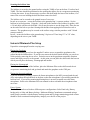
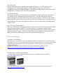
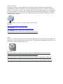
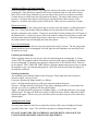
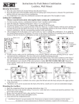
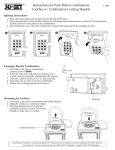
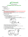
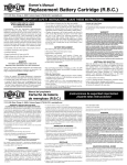
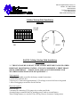
2801Youngfield Street, Suite 171
Golden, CO 80401-2266
303-456-5638
Toll Free 888-456-5638
Fax 303-456-5639
www.mathesonmining.com
Cellular Modem Field Installation
Diagram
SOLAR
PANEL
TAB
LID
SHELF
BASE
RAVEN Cellular Modem Field Installation
Instructions
*** THIS ENCLOSURE IS MEANT TO BE A THEFT DETTERENT AND WEATHER
RESISTANT MONITORING STATION. IT IS NOT COMPLETELY THEFT PROOF
OR WEATHERPROOF. PLEASE NOTE: MMC IS NOT RESPONSIBLE FOR
WEATHER DAMAGED OR STOLEN EQUIPMENT***
Tools required
5/16 and/or adjustable wrench for the battery terminal connections
1 pad lock for each lock box
2-4 pieces of 1/2 inch rebar (approximately 2-3 feet long) to secure lock box to the ground
1 shovel for digging a secure base for the lock box
Electrical required
Electrical tape
2 wirenuts for connecting 12-14 gauge wire on solar panel leads
4 terminal rings or terminal forks for attaching power leads to external battery
Timer Wiring harness (see attached Timer Wiring Harness document) if using a timer
Securing the lockbox base
The lockbox is secured to the ground surface using the TABS or feet on the base. Your box has 4
TABS. The base should be positioned so the opening that allows for air overpressure monitoring
is facing the source. It may be necessary to remove the shelf inside the base of the lockbox, if so
remove the set screw holding the shelf and then remove the shelf.
The lockbox can be secured to the ground in one of two ways:
In rock or on concrete – secure the lockbox to the ground using ½ concrete anchors. Set the
lockbox in its final position. Using the ½ hole tabs in the bottom of the lockbox for guides, drill
a 3-4 inch hole with the rock drill and ½ bit (It may be easier to use the longer bit). Place the nut
on the end of the bolt so you don’t damage the threads when tapping the bolt into the rock or
concrete. The geophone may be secured to the surface using a similar procedure with 3/8 inch
concrete anchors.
In soil – secure the lockbox to the ground using 2-4 pieces of 3 foot long 1/2” or 3/8” rebar,
depending on the size or your TABS.
Instantel Minimate Plus Setup
Unpack the seismograph from the carrying case.
Placing the Geophone
If you are monitoring in soil, use the supplied 3 anchor screws to attach the geophone to the
ground inside the lockbox base. If you have not removed the shelf inside the base you can do so
at this point by removing the set screw. Point the arrow on the geophone toward the vibration
source and firmly secure it to the ground. At this point you can place the shelf inside the base on
which you will place the battery, seismograph and modem.
Placing the Seismograph
With the shelf in the base of the lockbox, place the Minimate Plus on the shelf toward the air
overpressure monitoring hole and go ahead and attach the geophone to the GEO port.
Placing the linear microphone
If you are monitoring blasting, connect the linear microphone to the MIC port and push the end
of the microphone through the hole in the base so that the microphone is just sticking outside the
lockbox base. If you are not monitoring blasting there is no need to attach or use the linear
microphone. Refer to the Minimate Plus user manual on how to disable the microphone when
not in use.
Power System
The Lockbox can be used in three different power configurations. Solar Panel only, Battery
backup only or Solar and Battery backup. Matheson Mining Consultants recommends using a
small charge controller with the battery backup system and for longer monitoring periods a timer
should be used to maintain backup battery integrity over the life of the project.
Solar Panel Only
In this configuration, the 10 watt solar panel supplies DC power (~18-22V) directly to the
seismograph. The seismograph contains a voltage regulator that prevents the internal
seismograph battery from being overcharged. An additional backup battery is not needed in this
configuration. A modem is not used in this configuration.
External Battery Only
This setup is typically not used because the external battery is used to power the modem and is
not a backup for the seismograph except in special cases. The solar panel power leads are
attached to the solar controller which is then connected to the battery. The power cable for the
modem should be connected directly to battery for short term monitoring or to the timer for long
term monitoring. Be aware that the modem will draw current from the battery constantly unless
a timer is used.
Solar Panel and External Battery
The power cable for the seismograph should be connected directly to the solar panel power leads
upstream from the charge controller. The external battery is configured using the charge
controller and/or timer. The solar panel power leads are attached to the solar controller which is
then connected to the battery. The power cable for the modem should be connected directly to
battery for short term monitoring or to the timer for long term monitoring.
Power System Components
Solar Panel - 10 Watt Module
Small solar panels are difficult to find online. Matheson Mining Consultants stocks 10 watt solar panels
only as these are what we use in the Western United States to maintain batteries. You may need to obtain
a larger solar panel depending on your monitoring location as the 10 watt panel may not adequately
recharge your batteries.
To determine what type of solar insolation is in your area the following tool may be used.
http://www.wholesalesolar.com/Information-SolarFolder/SunHoursUSMap.html
External Battery – Sealed Lead Acid Battery
35 amp-hour ($86.99) and 20 amp-hour ($82.99) batteries are available from Batteries Plus.
http://www.batteriesplus.com/
Or you can order similar batteries online from a battery wholesaler such as batterywholesale.com
http://www.batterywholesale.com/
Charge Controller
The charge controller is connected between the solar panel and the external battery and maintains a
constant charge voltage into the battery. The solar panel output is typically 18V+ and this voltage can
damage a 12 volt battery over time. The charge controller will assure longer battery life is recommended
for any system that uses a backup battery. A small charge controller made by Morningstar is available to
order online from many solar power resellers. Matheson Mining Consultants recommends and uses the
following charge controller.
Morningstar SG-4, 4.5 amp, 12 volt solar charge controller ($30)
Purchase
http://www.solar-electric.com/sg-4.html
Specifications
http://lib.store.yahoo.net/lib/wind-sun/SunGuard.pdf
User Manual
http://lib.store.yahoo.net/lib/wind-sun/SunGuard-manual.pdf
Timer
The Timer is used to typically used to turn the modem off when there are periods where monitoring is not
taking place or when communications are unnecessary. The Flexcharge Programmable Timer ($85) is the
perfect tool to maintain longtime battery life.
Purchase
http://www.altestore.com/store/Enclosures-Electrical-Safety/Miscellaneous-ElectricalParts/Switches/Timers/FlexCharge-Digital-DC-Timer/p2342/
Manual
http://www.altestore.com/mmsolar/others/Flexcharge_Manual_Programable_Timer.pdf
Wiring Overview
http://www.altestore.com/mmsolar/others/Flexcharge_Overview_Programable_Timer.pdf
Installing the Battery & Charge Controller
Remove the battery from the box it was shipped in and place the battery on the shelf next to the
seismograph. Open the charge controller and connect terminals rings or forks to the red and
black wires on the charge controller so you can connect these wires to your battery terminals.
Connect the power cables from the solar panel to the battery. The white cable connects to the
positive (+) terminal of the battery which may be red and the black cable connects to the
negative (-) terminal of the battery which will be black. Make sure the connections are tight.
Placing the modem
Make sure you have a heavy duty plastic bag in which to store the modem, it will not function if
gets wet. Connect the antenna cable protruding from the underside of the lockbox LID to the
antenna connection on the modem. Connect the serial cable from the modem to the AUX port on
the Minimate Plus. Connect the power cable to the modem coming from the battery or timer and
seal the modem inside the plastic bag so that it cannot get wet in any way. The power light on
the modem should come on indicating the modem has power.
Power the seismograph
Connect the power cable directly to the solar panel leads using 2 wirenuts. The red charge light
should illuminate on the seismograph. If the red light does not illuminate you most likely have
the polarity reversed.
Checking the seismograph
With everything connected, you can now start the monitoring on the seismograph. You may
want to TEST the geophone and/or microphone connection and setup by pressing the test button
on the seismograph. If anything is not properly connected the LCD will read Check –followed
by the channel. GEO, TRAN OR VERT indicate vibration channels and you may have to replant
the geophone to get a level monitoring position. Check-Mic indicates the linear microphone is
not properly connected.
Checking the modem
The modem has four indicator lights on the front panel. These lights from left to right are:
Network, Signal, Activity, Power.
For proper operation the lights should be as follows:
Power – the light should always be solid green when the modem has power.
Network – the light should be solid green. If the light is flashing you haven’t connected to the
network yet or there is a problem with the cellular signal.
Signal – the light should be solid green or flashing rapidly. A solid light indicates a very strong
cellular signal. The light will flash more slowly as signal decreases until the light fails to blink
indicating no signal. If this occurs you will need to move the entire setup to an area with better
cellular signal.
Aiming the Solar Panel
The solar panel should be aimed as to capture the position of the sun at its highest solar gain
(typically from 10am – 2pm). This will allow the panel to recharge the battery daily.
FINALLY MAKE SURE THE LOCKBOX IS LOCKED WITH A PAD LOCK. WE
CANNOT BE RESPONSIBLE FOR STOLEN EQUIPMENT.
*** THIS ENCLOSURE IS MEANT TO BE A THEFT DETTERENT AND WEATHER
RESISTANT MONITORING STATION. IT IS NOT COMPLETELY THEFT PROOF
OR WEATHERPROOF. PLEASE NOTE: MMC IS NOT RESPONSIBLE FOR
WEATHER DAMAGED OR STOLEN EQUIPMENT***