1
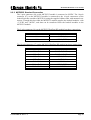
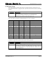
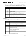
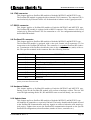
Kokkedal Industripark 4
DK-2980 Kokkedal
DENMARK
Tel:
+45 49 18 01 00
Fax:
+45 49 18 02 00
E-mail: [email protected]
MCE2035/MCE2535 PROFIBUS-DP MODULE
Standard weight function for digital loadcells
Applies for:
Cygnal no.:
MCE2535.WEIGHT.051103.1
Document no.:
1103MU1.DOC
Date:
2005-11-10
Rev.:
1
MCE2035/MCE2535: User manual
1) CONTENTS
1) CONTENTS.....................................................................................................................................2
2) INTRODUCTION ...........................................................................................................................3
2.1 Introduction.................................................................................................................................3
2.2 Profibus-DP specification ...........................................................................................................3
3) DATA EXCHANGE .......................................................................................................................4
3.1 PROFIBUS-DP communication using PPO ...............................................................................4
3.2 PCV Description .........................................................................................................................5
3.3 PCD Description .........................................................................................................................7
3.4 Data formats..............................................................................................................................10
3.4.1 Unsigned integer format (16 bit)....................................................................................10
3.4.2 Signed integer format (32 bit) ........................................................................................10
3.4.3 IEEE754 floating point format (32 bit) ..........................................................................11
4) PARAMETER LIST......................................................................................................................12
4.1 Parameter list ............................................................................................................................12
5) PARAMETER DESCRIPTION ....................................................................................................15
5.1 Parameter description................................................................................................................15
6) STATUS CODES ..........................................................................................................................18
7) ZEROING AND CALIBRATION ................................................................................................19
7.1 Zeroing procedure.....................................................................................................................19
7.2 Calibration procedure................................................................................................................19
8) INSTALATION OF SYSTEM ......................................................................................................21
8.1 Checklist during installation .....................................................................................................21
9) HARDWARE DESCRIPTION .....................................................................................................22
9.1 MCE2035/MCE2535 modul type designations ........................................................................22
9.2 Connection of power and loadcells...........................................................................................22
9.2.1 MCE2035 Standard Connection.....................................................................................22
9.2.2 MCE2535 Standard Connection.....................................................................................23
9.3 DIP-switch settings ...................................................................................................................24
9.4 Light Emitting Diodes...............................................................................................................25
9.5 Jumpers .....................................................................................................................................25
9.6 JTAG connector ........................................................................................................................26
9.7 RS232 connector.......................................................................................................................26
9.8 Profibus-DP connector..............................................................................................................26
9.9 Hardware Selftest......................................................................................................................26
9.10 Update times ...........................................................................................................................26
Version:2005-11-10 rev.: 1
Page: 2
MCE2035/MCE2535: User manual
2) INTRODUCTION
2.1 Introduction
This document describes the use of a MCE2535 Profibus-DP module as well as a
MCE2035 Profibus-DP module from Eilersen Electric, when they are equipped with the
program listed on the front page.
The two module types are the same, except that MCE2035 modules as opposed to
MCE2535 modules are encased in their own module box. Connectors and the way in
which the two module types are connected to power supply and loadcells, are therefore the
only differences between the two module types. These differences will appear in the chapters Connection of power and loadcells, while all other chapters will cover both MCE2535
as well as MCE2035 module types. In the following the designation MCE2535 will due to
the same reason cover both the MCE2535 and the MCE2035 module, unless it is specified
otherwise.
With the program specified on the front page, the MCE2535 Profibus-DP module can act
as weight for up to 16 loadcells. Each loadcell is connected to the Profibus-DP module
through a loadcell interface module.
It is possible to connect the MCE2535 Profibus-DP module to a Profibus-DP network,
where it will act as a slave. It will then be possible from the Profibus-DP master to read
status, read system weight and perform commands such as zeroing and calibration.
Exchange of data between master and slave takes place as described in the following.
2.2 Profibus-DP specification
The MCE2535 Profibus-DP module confirms to the following Profibus-DP specifications:
Protocol:
Communications form:
Module type:
Baud rates [kbit/sec]:
Profibus address:
Profibus connection:
Version:2005-11-10 rev.: 1
Profibus-DP
RS485
Slave
9.6, 19.2, 93.75, 187.5, 500, 1500 , 3000, 6000, 12000
0-127 (Sw2.2-Sw2.8)
9-pin sub-D (female) connector
Page: 3
MCE2035/MCE2535: User manual
3) DATA EXCHANGE
3.1 PROFIBUS-DP communication using PPO
PROFIBUS-DP communication with the MCE2535 communication module uses a so called
'parameter-process data object' (PPO) consisting of 14 bytes. This object is used during reception as well as during transmission of data. The structure of this telegram is as follows:
PCV
PCD
PCA
1
IND
2
3
PVA
4
5
CTW
STW
6
7
8
9
MRV
MAV
10
11
12
13
14
Byte 14
Byte 1
The telegram is made up of two blocks; a PCV part (the first 8 bytes) and a PCD part (the last
6 bytes). The two blocks are made up as follows:
PCV (Parameter-Characteristic-Value)
PCA (Bytes 1-2): Parameter Characteristics
IND (Bytes 3-4): Not used (reserved for future use)
PVA (Bytes 5-8): Parameter value
PCD (Process Data)
CTW (Bytes 9-10) (Master to Slave):
STW (Bytes 9-10) (Slave to Master):
MRV (Bytes 11-14) (Master to Slave):
MAV (Bytes 11-14) (Slave to Master):
Control Word
Status Word
Main Reference Value
Main Actual Value
In the following the meaning of the individual blocks in the telegram is described in detail.
The byte order (MSB/LSB first) for the individual parts is selected using jumper JU8, and
upon factory delivery it is default set to MSB byte first.
The data format of the MAV part and parameters in the PVA part is 32 bit signed integer
format (2’s complement). It is possible however, by using of jumper JU7 to change so that
the MAV part and certain parameters in the PVA part are transferred in IEEE754 floating
point format.
During transmission/reception of data consisting of several bytes (for example the MAV) it is
up to the master (the PLC) to provide for consistent (belonging together) data.
Version:2005-11-10 rev.: 1
Page: 4
MCE2035/MCE2535: User manual
3.2 PCV Description
The PCV part of the telegram is as mentioned made up of a PCA part, an IND part and a PVA
part. As mentioned the IND part is not used, but the functionality of the other two parts of the
PCV is described here.
PCA handling
The PCA part contains a RC part for 'request' and 'response' indication, and a PNU part for
indication of parameter number. This is shown in the figure of the PCA block below.
Bit 15
15
Bit 0
14
13
12
11
RC
RC:
TBD:
PNU:
10
9
8
7
6
TBD
5
4
3
2
1
0
PNU
Request/Response Characteristics
Not used
Parameter number
(Values: 0..15)
(Reserved for future use.)
(Values: 0..999)
RC - Request/Response Characteristics
The RC part is used by the master to tell the slave (the weight) what 'requests' are wanted.
Similarly the RC part is used by the slave to tell ('response') the master the status/results of the
received 'requests'. The RC part further informs which other parts of the PCV (IND and PVA)
are used.
The contents of the RC part has the following function during request:
REQUEST
0
No request
1
Request parameter value
2
Change parameter value (2 bytes)
3
Change parameter value (4 bytes)
4-15
Version:2005-11-10 rev.: 1
FUNCTION
Reserved for future use
Page: 5
MCE2035/MCE2535: User manual
The contents of the RC part has the following function during response:
RESPONSE
FUNCTION
0
No response
1
Transfer parameter value (2 bytes)
2
Transfer parameter value (4 bytes)
3
Request refused (incl. Error#, see later)
4
Can not be serviced by PCV interface
5-15
Reserved for future use
PNU - Parameter number
Bit 10 to Bit 0 in the PCA part indicates the parameter number of the parameter to be
read/changed. The individual parameters and their function is explained later.
PVA handling
The PVA part contains 4 bytes for reception and transmission of parameter values. The PVA
part will transfer '2 byte' parameters in either bytes 7-8 (MSB first selected) or bytes 5-6 (LSB
first selected). ‘4 byte’ parameters are transferred in bytes 5-8.
If the slave (the weight) refuses a request from the master the RC part will assume the value 3
(see above) and the actual error code will be transferred in the PVA element. The following
error indications are possible:
ERROR#
Version:2005-11-10 rev.: 1
CAUSE
0
Illegal PNU
1
Reserved for future use
2
Upper or lower limit is exceeded
Page: 6
MCE2035/MCE2535: User manual
3.3 PCD Description
As mentioned the PCD part of the telegram is made up of a CTW/STW part and a
MRV/MAV part. The functionality of the PCD parts is described here. Note that the PCD part
(the last 6 bytes) always transfers these data independent of the contents of the PCV part (the
first 8 bytes).
CTW handling
During communication from the master to the slave (the weight) the first two bytes in the
PCD part is used as a Control Word (CTW). By use of the Control Word (CTW) it is possible
to tell the slave (the weight) how it should react, as different commands can be transferred to
the weight.
The bit’s in CTW have the following function:
BIT-NO
FUNCTION
0
Reserved for future use
1
Zero system.
2
Calibrate corner.
3
Calibrate system.
4
Reset calibration.
5-14
15
Reserved for future use
Clear error in Error-register.
If the Zero system bit is activated all loadcells and thereby the calculated system weight will
be zeroed. This should only be done with an empty weighing arrangement.
If the Calibrate corner bit is activated the loadcell specified by the Corner-register will be
calibrated to the weight indicated by the Calibration load for corner/system register.
If the Calibrate system bit is activated the system weight will be calibrated to the weight
indicated by the Calibration load for corner/system register. Note that the individual calibration of the loadcells remains unchanged.
If the Reset calibration bit is activated all calibration factors (system and all loadcell factors)
will be set to their standard value of 32768.
If the Clear error in Error-register bit is activated any error in the Error-register will be
cleared.
Version:2005-11-10 rev.: 1
Page: 7
MCE2035/MCE2535: User manual
STW handling
During communication from slave (the weight) to the master the first two bytes in the PCD
part are used as a Status Word (STW). By reading the Status Word (STW) it is possible for
the master to achieve information on the status of the slave (the weight). The functionality of
the individual bits in the Status Word (STW) is described below:
BIT-NO FUNCTION
0
1-3
LC-error.
Reserved for future use
4
Zeroing OK.
5
Zeroing not possible.
6
Calibration OK.
7
Calibration not possible.
8
Reset Calibration OK.
9
Clear Error OK.
10-14
15
Reserved for future use
Error detected.
If the LC-error bit is ON one or more loadcells detected at power up are in an error state. The
actual error can be read in the Status for loadcell X register for the individual loadcell.
If the Zeroing OK bit is ON the last zero request has been performed. Note that the bit is
cleared during the zero process and after the Zero system bit is cleared again.
If the Zero not possible bit is ON the last zero request has not been performed. The reason
for this can be read in the Zeroing-register. Note that the bit is cleared during the zero process and after the Zero system bit is cleared again.
If the Calibration OK bit is ON the last calibration request has been performed. Note that the
bit is cleared during the calibration process and after both the Calibrate corner and Calibrate system bits are cleared again.
If the Calibration not possible bit is ON the last calibration request has not been performed.
The reason for this can be read in the Calibration-register. Note that the bit is cleared during
the calibration process and after both the Calibrate corner and Calibrate system bits are
cleared again.
If the Reset calibration OK bit is ON the last reset calibration request has been performed.
Note that the bit is cleared during the process and after the Reset calibration bit is cleared
again.
If the Clear error OK bit is ON the last clear error request has been performed. Note that the
bit is cleared during the process and after the Clear error in Error-register bit is cleared
again.
Version:2005-11-10 rev.: 1
Page: 8
MCE2035/MCE2535: User manual
If the Error detected bit is ON the system has detected an error. The actual error can be
found in the Error-register.
MRV handling
During communication from the master to the slave (the weight) the four last bytes in the
PCD part are used as a Main Reference Value (MRV); a setpoint. The Main Reference
Value (MRV) has no function in this program.
MAV handling
During communication from the slave (the weight) to the master the four last bytes in the
PCD part are used as a Main Actual Value (MAV); the actual value. The Main Actual Value
(MAV) is used to transfer the actual gross weight of the system. The gross weight must be
scaled in accordance to the Exponent for MAV parameter (Par.No.=15) if Gram mode has
not been selected using jumper JU1. Default factory setting is that Gram mode is not selected. Note that the MAV part may be transferred in 32 bit signed integer format (default) or
in IEEE754 floating point format depending on the actual jumper setting.
Version:2005-11-10 rev.: 1
Page: 9
MCE2035/MCE2535: User manual
3.4 Data formats
The Profibus-DP communication can transfer data in the following three data formats. If
necessary please refer to other literature for further information on these formats.
3.4.1 Unsigned integer format (16 bit)
The following are examples of decimal numbers represented on 16 bit unsigned integer
format:
Decimal
0
1
2
200
2000
20000
Hexadecimal
0x0000
0x0001
0x0002
0x00C8
0x07D0
0x4E20
Binary (MSB first)
00000000
00000000
00000000
00000000
00000111
01001110
00000000
00000001
00000010
11001000
11010000
00100000
3.4.2 Signed integer format (32 bit)
The following are examples of decimal numbers represented on 32 bit signed integer format:
Decimal
Hexadecimal
-20000000
-2000000
-200000
-20000
-2000
-200
-2
-1
0
1
2
200
2000
20000
200000
2000000
20000000
0xFECED300
0xFFE17B80
0xFFFCF2C0
0xFFFFB1E0
0xFFFFF830
0xFFFFFF38
0xFFFFFFFE
0xFFFFFFFF
0x00000000
0x00000001
0x00000002
0x000000C8
0x000007D0
0x00004E20
0x00030D40
0x001E8480
0x01312D00
Version:2005-11-10 rev.: 1
Binary (MSB first)
11111110
11111111
11111111
11111111
11111111
11111111
11111111
11111111
00000000
00000000
00000000
00000000
00000000
00000000
00000000
00000000
00000001
11001110
11100001
11111100
11111111
11111111
11111111
11111111
11111111
00000000
00000000
00000000
00000000
00000000
00000000
00000011
00011110
00110001
11010011
01111011
11110010
10110001
11111000
11111111
11111111
11111111
00000000
00000000
00000000
00000000
00000111
01001110
00001101
10000100
00101101
00000000
10000000
11000000
11100000
00110000
00111000
11111110
11111111
00000000
00000001
00000010
11001000
11010000
00100000
01000000
10000000
00000000
Page: 10
MCE2035/MCE2535: User manual
3.4.3 IEEE754 floating point format (32 bit)
Representation of data on IEEE754 floating point format is done as follows:
Byte1
Byte2
Byte3
Byte4
bit7 bit6
bit0 bit7 bit6
bit0 bit7
bit0 bit7
bit0
7
1
0
-1
-7
-8
-15
-16
S
2 …..…. 2
2
2 ……... 2 2 ………….... 2
2 ………..…. 2-23
Sign
Exponent
Mantissa
Mantissa
Mantissa
Formula:
Value = (-1)S * 2(exponent-127) * (I+Mantissa)
Example:
Byte1
0100 0000
Byte2
1111 0000
Byte3
0000 0000
Byte4
0000 0000
Value = (-1)0 * 2(129-127) * (1 + 2-1 + 2-2 + 2-3) = 7.5
Please note that if transfer of MSB first has been selected (default setting), the byte with
the “sign” will come first in the weight indications, and if LSB first has been selected the
byte with the “sign” will come last in the weight indications.
Version:2005-11-10 rev.: 1
Page: 11
MCE2035/MCE2535: User manual
4) PARAMETER LIST
4.1 Parameter list
A part from main values (MRV/MAV) and control/status word (CTW/STW), which are
transferred at all times using the PCD part, it is possible to access the individual parameters
one at a time using the PCV part. The following parameters can be read/updated using the
PCV part:
NO
TYPE
PARAMETER
0
2R
1
2 RW
2-6
2
7
2R
Error-register
Bit register for indication of detected errors.
8
2R
Zeroing-register
Bit register for indication of errors during zeroing.
9
2R
Calibration-register
Bit register for indication of errors during calibration.
10-14
2
15
2R
Exponent for MAV
16
17
18
19
20
21
22
23
24
25
26
27
28
29
30
31
2R
2R
2R
2R
2R
2R
2R
2R
2R
2R
2R
2R
2R
2R
2R
2R
Exponent for loadcell 0
Exponent for loadcell 1
Exponent for loadcell 2
Exponent for loadcell 3
Exponent for loadcell 4
Exponent for loadcell 5
Exponent for loadcell 6
Exponent for loadcell 7
Exponent for loadcell 8
Exponent for loadcell 9
Exponent for loadcell 10
Exponent for loadcell 11
Exponent for loadcell 12
Exponent for loadcell 13
Exponent for loadcell 14
Exponent for loadcell 15
LC-register
Bit register for indication of connected loadcells detected during power-up.
Corner-register
Indicates corner (loadcell number) to be corner calibrated.
Reserved for future use
Reserved for future use
Version:2005-11-10 rev.: 1
Page: 12
MCE2035/MCE2535: User manual
32
33
34
35
36
37
38
39
40
41
42
43
44
45
46
47
48
49
50
51
52
53
54
55
56
57
58
59
60
61
62
63
64
65
66
67
68
69
70
71
72
73
74
75
76
77
78
79
80*
81*
2R
2R
2R
2R
2R
2R
2R
2R
2R
2R
2R
2R
2R
2R
2R
2R
4R
4R
4R
4R
4R
4R
4R
4R
4R
4R
4R
4R
4R
4R
4R
4R
4R
4R
4R
4R
4R
4R
4R
4R
4R
4R
4R
4R
4R
4R
4R
4R
4 RW
4 RW
Status for loadcell 0
Status for loadcell 1
Status for loadcell 2
Status for loadcell 3
Status for loadcell 4
Status for loadcell 5
Status for loadcell 6
Status for loadcell 7
Status for loadcell 8
Status for loadcell 9
Status for loadcell 10
Status for loadcell 11
Status for loadcell 12
Status for loadcell 13
Status for loadcell 14
Status for loadcell 15
Actual gross weight for loadcell 0
Actual gross weight for loadcell 1
Actual gross weight for loadcell 2
Actual gross weight for loadcell 3
Actual gross weight for loadcell 4
Actual gross weight for loadcell 5
Actual gross weight for loadcell 6
Actual gross weight for loadcell 7
Actual gross weight for loadcell 8
Actual gross weight for loadcell 9
Actual gross weight for loadcell 10
Actual gross weight for loadcell 11
Actual gross weight for loadcell 12
Actual gross weight for loadcell 13
Actual gross weight for loadcell 14
Actual gross weight for loadcell 15
Actual signal for loadcell 0
Actual signal for loadcell 1
Actual signal for loadcell 2
Actual signal for loadcell 3
Actual signal for loadcell 4
Actual signal for loadcell 5
Actual signal for loadcell 6
Actual signal for loadcell 7
Actual signal for loadcell 8
Actual signal for loadcell 9
Actual signal for loadcell 10
Actual signal for loadcell 11
Actual signal for loadcell 12
Actual signal for loadcell 13
Actual signal for loadcell 14
Actual signal for loadcell 15
Actual zero for loadcell 0
Actual zero for loadcell 1
Version:2005-11-10 rev.: 1
Page: 13
MCE2035/MCE2535: User manual
82*
83*
84*
85*
86*
87*
88*
89*
90*
91*
92*
93*
94*
95*
96*
97*
98*
99*
100*
101*
102*
103*
104*
105*
106*
107*
108*
109*
110*
111*
112*
4 RW
4 RW
4 RW
4 RW
4 RW
4 RW
4 RW
4 RW
4 RW
4 RW
4 RW
4 RW
4 RW
4 RW
4 RW
4 RW
4 RW
4 RW
4 RW
4 RW
4 RW
4 RW
4 RW
4 RW
4 RW
4 RW
4 RW
4 RW
4 RW
4 RW
4 RW
Actual zero for loadcell 2
Actual zero for loadcell 3
Actual zero for loadcell 4
Actual zero for loadcell 5
Actual zero for loadcell 6
Actual zero for loadcell 7
Actual zero for loadcell 8
Actual zero for loadcell 9
Actual zero for loadcell 10
Actual zero for loadcell 11
Actual zero for loadcell 12
Actual zero for loadcell 13
Actual zero for loadcell 14
Actual zero for loadcell 15
Corner calibration factor for loadcell 0
Corner calibration factor for loadcell 1
Corner calibration factor for loadcell 2
Corner calibration factor for loadcell 3
Corner calibration factor for loadcell 4
Corner calibration factor for loadcell 5
Corner calibration factor for loadcell 6
Corner calibration factor for loadcell 7
Corner calibration factor for loadcell 8
Corner calibration factor for loadcell 9
Corner calibration factor for loadcell 10
Corner calibration factor for loadcell 11
Corner calibration factor for loadcell 12
Corner calibration factor for loadcell 13
Corner calibration factor for loadcell 14
Corner calibration factor for loadcell 15
Calibration factor for system
113
4 RW
Calibration load for corner/system
114-127
4
Reserved for future use
Note that NO indicates the parameter number for the parameter in question.
Note that TYPE indicates the length of the parameter in question (2 = 2 bytes and 4 = 4
bytes). In addition after the length it is indicated whether its a read and write register (RW =
ReadWrite) or its a read only register (R = Read).
Note that data values are transferred as 2 complement signed values.
Note that a * after the parameter number indicates that the parameter in question is stored in
the SEEPROM of the module, why this parameter can be remembered after power has been
disconnected. Please note that no zeroing or calibration is performed at power-up.
Version:2005-11-10 rev.: 1
Page: 14
MCE2035/MCE2535: User manual
5) PARAMETER DESCRIPTION
5.1 Parameter description
The individual parameters have the following functions:
LC-register is a bit register for indication of connected loadcells detected at power-up. Hence
bit 0-15 will be ON, if the corresponding loadcell was detected during power-up..
Corner-register indicates which corner (loadcell number) that has to be corner calibrated.
The loadcell number corresponds to the loadcell module address. Hence values in the interval
0-15 are valid. Values in the interval 16-65535 indicates that the calibration corner is not selected.
Error-register is a bit register for indication of detected errors. The individual bits have the
following function:
BIT-NO FUNCTION
0
A checksum error for storage of zero and calibration in the SEEPROM of the
module was detected during power-up.
1
A calibration factor was out of range during power-up (or scale is not calibrated).
2
A zero was invalid during power-up (or scale has not been zeroed).
3
Inconsistency between number of detected loadcells during power on and the
number of loadcells indicated using Sw1.1-Sw1.4.
4-15
Reserved for future use
Zero-register is a bit register for indication of errors during zero. The individual bits have the
following function:
BIT-NO
0
1-15
Version:2005-11-10 rev.: 1
FUNCTION
LC-error during zero
Check status for the individual loadcells.
Reserved for future use
Page: 15
MCE2035/MCE2535: User manual
Calibration-register is a bit register for indication of errors during calibration. The individual
bits have the following function:
BIT-NO
FUNCTION
0
LC-error during calibration
Check status for the individual loadcells.
1
Calibration load not selected/valid
Check that a valid calibration load has been selected.
2
Calibration corner not selected/valid
Check that a valid calibration corner has been selected.
3
Calibration range exceeded
It was not possible to calibrate the system within the valid calibration
range. Check that nothing is affecting the weighing arrangement mechanically. Check that the value in the Calibration load for corner/system register corresponds to the actual load.
4
Gross weight was negative during calibration
Check the gross weight and whether it shows zero without any load.
5-15
Reserved for future use
Exponent for MAV is a register containing the exponent for the MAV. If Gram mode has
not been selected using jumper JU1, the transferred gross weight has to be compared with this
exponent. It indicates the "resolution” of the MAV (gross weight) as described under Exponent for loadcell X. The exponent corresponds to the smallest loadcell exponent.
Exponent for loadcell X is a register containing the exponent of loadcell X. The transferred
weighing result has to be compared with the exponent for the loadcells. The exponent is a
fixed value (2 complement) for a given loadcell, and it indicates the "resolution" of the loadcell (weighing result) as follows:
Exponent
[Decimal]
Exponent
[Hexadecimal]
Conversion factor
to gram
SI unit
-3
-2
-1
0
1
2
3
4
5
6
0xFFFD
0xFFFE
0xFFFF
0x0000
0x0001
0x0002
0x0003
0x0004
0x0005
0x0006
*10-3
*10-2
*10-1
*100
*101
*102
*103
*104
*105
*106
mg
Version:2005-11-10 rev.: 1
gram
Kg
ton
Page: 16
MCE2035/MCE2535: User manual
Status for loadcell X is a register containing the actual status for loadcell X. The meaning of
the status code can be found in the STATUS CODES chapter.
Actual gross weight for loadcell X contains the actual gross weight for loadcell X. The gross
weight is the actual load signal for the loadcell adjusted by zero and calibration factor. Note
that the value is a value averaged over 200 ms.
Actual signal for loadcell X contains the actual signal for loadcell X. The actual signal is the
actual load signal for the loadcell without any adjustment fir zero and calibration factor. Note
that the value is a value averaged over 200 ms.
Actual zero for loadcell X contains the actual zero value for loadcell X. The value is determined during zero from Actual signal for loadcell X.
Corner calibration factor for loadcell X contains the calibration factor for loadcell X. The
value is determined during calibration of corner X, and lies in the interval 24576-40960 with
32768 as center value (standard calibration factor corresponding to no calibration).
Calibration factor for system contains the system calibration factor. The value is determined
during calibration of the system, and lies in the interval 24576-40960 with 32768 as center
value (standard calibration factor corresponding to no calibration).
Calibration load for corner/system must contain the load used during calibration of the system or corner. Note that this parameter is always transferred in the same format as the MAV.
The format may vary depending on the actual jumper settings (MSB/LSB first, SI32/IEEE754
format and Standard/Gram mode).
Version:2005-11-10 rev.: 1
Page: 17
MCE2035/MCE2535: User manual
6) STATUS CODES
Status codes are shown as a 4 digit hex number. If more than one error condition
is present the error codes are OR’ed together.
CODE
(Hex)
0001
0002
0004
0008
0010
0020
0040
0080
0100
0200
0400
0800
1000
2000
4000
8000
CAUSE
Invalid/missing ’sample’ ID
Bad connection between communication module and loadcell module. Not
all telegrams from communication module are received in loadcell module.
Loadcell timeout
Check that the loadcell is connected to the loadcell module.
Loadcell not synchronized
Bad connection between loadcell and loadcell module, or very powerful under- or overload.
Hardware synchronization error
Loadcell samples are not synchronized. Cable between loadcell modules
shorted or disconnected.
Power failure
Supply voltage to loadcells is to low.
Overflow in weight calculation
Internal error in loadcell module.
Invalid/missing ’latch’ ID
Bad connection between communication module and loadcell module. Not all
telegrams from communication module is received in loadcell module.
No answer from loadcell module
No data is received from this loadcell module. This can be caused by the removal of the loadcell module, no power to the module or that the connection
between loadcell module and communication module is broken.
Reserved for future use
Reserved for future use
Reserved for future use
No loadcell modules answer
Bad connection between communication module and loadcell module. Not all
telegrams from communication module are received in loadcell module.
Reserved for future use
Reserved for future use
Reserved for future use
Wrong number of loadcells
The number of detected loadcells at power-up does not match the number
indicated on Sw1.1-Sw1.4.
Version:2005-11-10 rev.: 1
Page: 18
MCE2035/MCE2535: User manual
7) ZEROING AND CALIBRATION
7.1 Zeroing procedure
Zeroing of the system (all loadcells) should be done using the following procedure:
1)
The weighing arrangement should be empty and clean.
2)
The Zero system bit in the Control Word is activated. Note that zeroing is only done
on the 0-1 transition.
3)
By reading the Zeroing OK and the Zeroing not possible bits it is possible to read
the result of the desired zeroing. If zeroing is not possible the reason can be read in
the Zeroing-register.
It is always possible to read the achieved or used zero by reading from the parameter numbers
where the loadcell zeroes are stored.
If in possession of a zero from a previous zeroing it is possible to insert this zero by writing to
the parameter numbers where the loadcell zeroes are stored.
Note that no zeroing is performed at power-on.
7.2 Calibration procedure
Fine calibration of the system should be performed using the following procedure:
1)
Check that the weighing arrangement is empty, and that the gross weight is zero.
Zero if necessary.
2)
Place a known load on the weighing arrangement.
3)
Transfer the value for the known load to the Calibration load for corner/system
register.
4)
The Calibrate system bit in the Control Word is activated. Note that calibration is
only done on the 0-1 transition.
5)
By reading the Calibration OK and the Calibration not possible bits it is possible
to read the result of the desired calibration. If calibration is not possible the reason
can be read in the Calibration-register.
6)
If Calibration OK is indicated the transferred gross weight should now match the
used calibration load and the calibration factor has been updated. If Calibration not
possible is indicated the system calibration factor is not changed.
If a corner calibration of the weighing arrangement is desired, the above listed procedure can
still be used as the following is taken into account:
Version:2005-11-10 rev.: 1
Page: 19
MCE2035/MCE2535: User manual
1)
Corner calibration should be performed prior to system calibration. During corner
calibration the Calibration factor for system should be set to its standard value of
32768.
2)
Corner calibration is done one corner at a time, where the above listed procedure is
used for each corner.
3)
The actual calibration corner is selected in the Corner-register prior to start of corner calibration. The corner number corresponds to the loadcell communication address which is set on the matching loadcell module. If in doubt the loadcell number
can be verified by finding the Actual gross weight for loadcell X, which gives a
corresponding signal change when a load is placed/removed directly above the actual loadcell.
4)
It is the Calibrate corner bit in the Control Word (CTW), that has to be activated
and not the Calibrate system bit.
5)
The used calibration load must be placed directly above the actual loadcell, so that it
is this loadcell that absorbs the "entire" load.
6)
It is not the system gross weight, that has to be observed but the Actual gross
weight for loadcell X. If the other loadcells are completely unloaded, this value
should correspond with the system gross weight.
7)
Every corner calibration only changes the calibration factor for the corresponding
corner. The other corner and system calibration factors remain unchanged.
It is always possible to read the achieved or used calibration factors by reading from the parameter numbers where the calibration factors are stored.
If in possession of calibration factors from a previous calibration, it is possible to insert these
by writing to the parameter numbers where the calibration factors are stored.
Note that no calibration is performed at power-on.
Version:2005-11-10 rev.: 1
Page: 20
MCE2035/MCE2535: User manual
8) INSTALATION OF SYSTEM
8.1 Checklist during installation
During installation of the system the following should be checked:
1)
2)
3)
4)
5)
6)
7)
8)
9)
10)
11)
12)
13)
14)
15)
The Profibus-DP master should be configured to communicate with the ProfibusDP module (MCE2035/MCE2535) using the supplied GSD file. When configuring
with the GSD file always select a MCE2535 station type. This also applies for a
MCE2035 module.
All hardware connections mentioned below are made as described depending on
whether it is a MCE2035 module or a MCE2535 module.
The loadcells are mounted mechanically and connected to the Profibus-DP module
using their corresponding loadcell interface module. The loadcell addresses are set
using the DIP-switches on the loadcell interface modules, so that they forth running from address 0 (0-15). The number of connected loadcells is set on the
Profibus-DP module using Sw1.1-Sw1.4 as described below.
The Profibus-DP module is connected to the Profibus-DP network, and possibly a
termination is made at this Profibus-DP slave.
The address of the Profibus-DP module is set using Sw2.2-Sw2.8. Power is applied and the Profibus-DP communication is started.
Verify that the red LED (PBE) on the Profibus-DP module is NOT lit, and that the
yellow LEDs (DES and RTS) are lit/flashing. Verify that the TXBB LED on the
Profibus-DP module is lit and that the TXBB LED’s on the loadcell interface
modules are also lit (can flash slightly).
Verify that the Profibus-DP module has found the correct loadcells (Par.No.=0),
and that no loadcell errors are indicated in the Status Word (STW).
Check that the loadcell exponents (Par.No.=16-31) are identical.
Reset all calibration factors by using the Reset Calibration bit in the Control Word
(CTW).
Zero the system weight with empty weighing arrangement by using the “Zeroing
procedure” described earlier.
Verify that every loadcell gives a signal (Par.No.=48-63) by placing a load directly
above each loadcell one after the other (possibly with a known load).
Place a known load on the weighing arrangement, and check that the system
weight (MAV) corresponds to the load. Does the master take the exponent (scaling) into account if Gram mode has not been selected?
Zero the system weight with empty weighing arrangement by using the “Zeroing
procedure” described earlier.
Place a known load (as close to maximum load as possible) on the weighing arrangement.
If the system weight deviates to much from the actual load a fine calibration of the
system is made using the “Calibration procedure” described earlier.
The system is now installed and a final check is made before the system is taken into usage. Possibly make a note of all zeroes (Par.No.=80-95) and calibration factors
(Par.No,=96-112) for later use.
Note that in the above checklist no consideration has been made on which functions are
implemented on the Profibus-DP master.
Version:2005-11-10 rev.: 1
Page: 21
MCE2035/MCE2535: User manual
9) HARDWARE DESCRIPTION
9.1 MCE2035/MCE2535 modul type designations
The Profibus-DP module is designated as either a MCE2035 module or a MCE2535 module. The two module types are the same, except that MCE2035 modules as opposed to
MCE2535 modules are encased in their own module box. Connectors and the way in
which the two module types are connected to power supply and loadcells, are therefore the
only differences between the two module types. These differences will appear in the chapters Connection of power and loadcells.
9.2 Connection of power and loadcells
This chapter describes the connection of power supply and loadcells for a MCE2035 module and a MCE2535 module respectively.
9.2.1 MCE2035 Standard Connection
The 10 pole connector (J2) on the MCE2035 module is connected to the 10 pole connectors on the loadcell interface modules (MCE9610/MCE2010) and to the 10 pole connector
on the MCE9601 connection module using the supplied ribbon cable with mounted connectors. Through this bus cable connection of power supply to the individual modules is
achieved and data can be transferred from the loadcell modules to the MCE2035 module.
The MCE9601 module has the following connections in the blue connector (J1):
MCE9601 CONNECTOR
CONNECTION
GND
B (DATA- )
A (DATA+)
GND
+24V
GND
I/O
+24VDC (Vin)
0 VDC (GNDin)
-
The 10 pole connector (J2) on the MCE2035 Profibus-DP module has these connections:
Version:2005-11-10 rev.: 1
MCE2035 J2 CONNECTER
FUNCTION
J2.1 - J2.2
J2.3 - J2.4
J2.5 - J2.6
J2.7 - J2.8
J2.9 - J2.10
RS485-B (DATA- )
RS485-A (DATA+)
0 VDC (GNDin)
+24VDC (Vin)
I/O line
Page: 22
MCE2035/MCE2535: User manual
9.2.2 MCE2535 Standard Connection
The 2 pole connector (J6) on the MCE2535 module is connected to 24VDC. The 14 pole
connector (J7) on the MCE2535 module is connected to the 14 pole connectors on the
loadcell interface modules (MCE2510) using the supplied ribbon cable with mounted connectors. Through this bus cable the MCE2535 module supplies the loadcell modules with
+3.3VDC and +24VDC, and data can be transferred from the loadcell modules to the
MCE2535 module.
The 2 pole connector (J6) on the MCE2535 Profibus-DP module has these connections:
MCE2535 J6 CONNECTOR
CONNECTION
J6.1
J6.2
+24VDC (Vin)
0 VDC (GNDin)
The 14 pole connector (J7) on the MCE2535 Profibus-DP module has these connections:
MCE2535 J7 CONNECTER
FUNCTION
J2.1 - J2.2
J2.3 - J2.4
J2.5 - J2.6
J2.7 - J2.8
J2.9 - J2.10
J2.11 - J2.12
J2.13 - J2.14
RS485-B (DATA- )
RS485-A (DATA+)
0 VDC (GNDin)
+24VDC (Vin)
I/O line
0 VDC (GNDin)
+3.3VDC
Version:2005-11-10 rev.: 1
Page: 23
MCE2035/MCE2535: User manual
9.3 DIP-switch settings
This chapter applies to Profibus-DP modules of both the MCE2035 and MCE2535 type.
The Profibus-DP module is equipped with a 4 pole DIP-switch block that has the following
function:
SWITCH
Sw1.1-Sw1.4
FUNCTION
Expected number of loadcells
The expected number of loadcells is set as indicated below.
Note that these switches are only read at power-up.
where the number of loadcells is indicated using Sw1.1-Sw1.4 as follows:
Sw1.1
Sw1.2
Sw1.3
Sw1.4
Number of loadcells
OFF
OFF
OFF
OFF
OFF
OFF
OFF
OFF
ON
ON
ON
ON
ON
ON
ON
ON
OFF
OFF
OFF
OFF
ON
ON
ON
ON
OFF
OFF
OFF
OFF
ON
ON
ON
ON
OFF
OFF
ON
ON
OFF
OFF
ON
ON
OFF
OFF
ON
ON
OFF
OFF
ON
ON
OFF
ON
OFF
ON
OFF
ON
OFF
ON
OFF
ON
OFF
ON
OFF
ON
OFF
ON
16
1
2
3
4
5
6
7
8
9
10
11
12
13
14
15
In addition a 8 pole DIP-switch block that has the following function:
SWITCH
Sw2.1
Sw2.2-Sw2.8
Version:2005-11-10 rev.: 1
FUNCTION
Reserved for future use
Selection of Profibus-DP communication address
The address is selected as the DIP-switches are binary coded, so
Sw2.2 is MSB and Sw2.8 is LSB. Note that these switches are only
read during power on.
Page: 24
MCE2035/MCE2535: User manual
9.4 Light Emitting Diodes
This chapter applies to Profibus-DP modules of both the MCE2035 and MCE2535 type.
The Profibus-DP module is equipped with 6 light emitting diodes (LED). These LED’s
have the following function:
LED
TXBB
(Green)
D1
(Green)
D2
(Green)
PBE
(Red)
DES
(Yellow)
RTS
(Yellow)
FUNCTION
Communication with loadcells
Profibus-DP module is communicating with loadcells.
Reserved for future use
Reserved for future use
Profibus Error (when initializing the SPC3)
The SPC3 Profibus-DP controller was not initialized correctly.
Data Exchange State
Exchange of data between Profibus-DP slave and master.
RtS signal (SPC3)
The Profibus-DP module sends to the master.
9.5 Jumpers
This chapter applies to Profibus-DP modules of both the MCE2035 and MCE2535 type.
The Profibus-DP module is equipped with 7 jumpers. These jumpers have these functions:
JUMPER
JU1
FUNCTION
Selection of (Standard mode) / (Gram mode)
The jumper determines if certain weight indications in the telegram are in standard
format (must be scaled according to the exponent) or directly in grams.
OFF: Standard mode (normal setting from factory)
ON: Gram mode
JU2-JU4
Reserved for future use (termination)
(normal default factory setting is OFF)
JU6
Reserved for future use
(normal default factory setting is OFF)
JU7
Selection of (32 Bit Signed Integer) / (IEEE754) data format
The jumper determines if certain weight indications in the telegram are in 32 bit
signed integer or in IEEE754 floating point format.
OFF: 32 bit signed integer format (normal setting from factory)
ON: IEEE754 floating point format
JU8
Selection of LSB/MSB data format
The jumper determines the byte order in which data are transmitted/received.
OFF: LSB first
ON: MSB first (normal setting from factory)
Version:2005-11-10 rev.: 1
Page: 25
MCE2035/MCE2535: User manual
9.6 JTAG connector
This chapter applies to Profibus-DP modules of both the MCE2035 and MCE2535 type.
The Profibus-DP module is equipped with an internal JTAG connector. The connector (J5) is
used exclusively by Eilersen Electric A/S for download of software to the Cygnal processor.
9.7 RS232 connector
This chapter applies to Profibus-DP modules of both the MCE2035 and MCE2535 type.
The Profibus-DP module is equipped with an RS232 connector. The connector (J4) is used
exclusively by Eilersen Electric A/S for connection to a PC for configuration/monitoring of
the Profibus-DP module.
9.8 Profibus-DP connector
This chapter applies to Profibus-DP modules of both the MCE2035 and MCE2535 type.
The Profibus-DP module is equipped with a nine pole female sub-D connector (J1) for
connection to the Profibus-DP network. The connector is a standard Profibus-DP connector. Termination of the Profibus should take place in the sub-D connector (male) of the cable. The specific terminals in the connector have the following function:
J1 TERMINALS
J1.1
J1.2
J1.3
J1.4
J1.5
J1.6
J1.7
J1.8
J1.9
FUNCTION
Not used
Not used
RS485-A (positive line) (Siemens designation: B line)
Request to Send (RTS)
0 VDC (Gnd)
+5VDC (Vout)
Not used
RS485-B (negative line) (Siemens designation: A line)
Not used
Note that some companies use different designations for the RS485-A and the RS485-B lines. Therefore the
polarity of the lines has been listed.
9.9 Hardware Selftest
This chapter applies to Profibus-DP modules of both the MCE2035 and MCE2535 type.
During power-on the Profibus-DP module will perform a hardware selftest. The test will
cause the light emitting diodes D1, D2 and PBE to turn on and off shortly, one at a time.
9.10 Update times
This chapter applies to Profibus-DP modules of both the MCE2035 and MCE2535 type.
All loadcells are sampled over a period of 200 mS. The hereby found loadcell signals are used
in the Profibus-DP communication until new signals are achieved when the next sample period expires. Update times across the Profibus-DP communication depends on the specific
Profibus-DP configuration (selected baudrate, number of slaves, scan times etc.).
Version:2005-11-10 rev.: 1
Page: 26