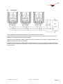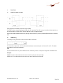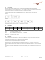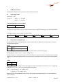
1
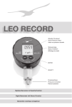
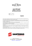
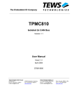
Description of the
Communication Protocol
for Series 4 LD ... 9LD OEM pressure transmitter from KELLER
Version 2.3
KELLER AG für Druckmesstechnik
Version 2.3 hof 03. Mar. 2014
1
Introduction ............................................................................................................................................................................ 3
2 Electrical Interface ................................................................................................................................................................. 3
2.1 Pinout .................................................................................................................................................................................... 3
2.2 Pull-up Resistors ................................................................................................................................................................... 4
2.3 Bit Rate ................................................................................................................................................................................. 4
2.4 Bus Capability ....................................................................................................................................................................... 5
3 Data Frame.............................................................................................................................................................................. 6
3.1 START and STOP Condition ................................................................................................................................................ 6
3.2 ADDRessing.......................................................................................................................................................................... 6
3.3 ACKnowledge ....................................................................................................................................................................... 7
3.4 STATUS Byte........................................................................................................................................................................ 7
3.5 DATA Bytes........................................................................................................................................................................... 7
4 Get Measurement Data .......................................................................................................................................................... 8
4.1 Get the digital Values ............................................................................................................................................................ 8
4.2 Interpretation of the digital Values......................................................................................................................................... 8
4.3 Variants to detect the End Of Conversion........................................................................................................................... 10
4.4 Voltage-Time-Diagrams ...................................................................................................................................................... 11
5 Optional further Commands ............................................................................................................................................... 12
5.1 Memory-Map of User Information ....................................................................................................................................... 12
5.2 Recommended Slave Addresses........................................................................................................................................ 14
5.3 Changing the Slave Address............................................................................................................................................... 15
6 K-404 User Manual ............................................................................................................................................................... 16
6.1 USB-to-I2C Dongle ............................................................................................................................................................. 16
6.2 PC Application to change the Slave Address...................................................................................................................... 18
7 Appendix............................................................................................................................................................................... 22
7.1 Code Examples................................................................................................................................................................... 22
7.2 Application Notes ................................................................................................................................................................ 24
7.3 Protocol Changes................................................................................................................................................................ 24
7.4 Firmware Versions .............................................................................................................................................................. 24
7.5 Support................................................................................................................................................................................ 24
Communication Protocol 4 LD ... 9 LD
Version 2.3 hof 03. Mar. 2014
Page 2/24
1
Introduction
Visually the Series 4 LD … 9 LD are like standard KELLER pressure transducers with a 5 pin interface to connect the half-open
Wheatstone Bridge. But these I2C versions contain beside the pressure sensor a very tiny signal conditioner. This results in an
OEM pressure transmitter with a digital interface. The “D” stands for “digital” and for “dual”; the LD-Line provides pressure and
temperature information.
The most important topics regarding the communication with the Series 4 LD … 9 LD and KELLER’s unique embedded DSP
core, are listed in this protocol description - especially the interpretation of the readout values.
For more information about the I2C specification please visit the NXP website and have a look at the User Manual in the documents section. I2C is a licence free standard since 2006: http://www.nxp.com/documents/user_manual/UM10204.pdf
2
Electrical Interface
2.1
Pinout
Notes
Be careful with the glazed pins, cracks in the glass pills causes leakage => damage
Do not touch the steel diaphragm!
Cabling
There are no special requirements to the wires or a flexible printed circuit (FPC) depending on the cross section because the current consumption is very low.
Sleep-Mode typ. 100nA
Active-Mode typ. 1.5mA (during conversion in less than 6.5ms, typ. 5ms)
Be careful with cabling over more than a few centimetres. The I2C-Bus is not a fieldbus and only EMC safe if the interconnections
are short or screened by the surrounding housing of the whole application or a suitable cable.
Communication Protocol 4 LD ... 9 LD
Version 2.3 hof 03. Mar. 2014
Page 3/24
2.2
Pull-up Resistors
Pull-up resistors are needed at SDA and SCL. 1..10kOhm are recommended. In order to optimise the data rate or low power
consumption, other resistance values are possible.
The EOC-Pin supplies an active high level in idle state and an active low level during conversion.
The SCL and the SDA lines are open drain driven. The wired-AND circuits avoid level collisions. Additional series resistors
placed directly at the bus members leads to even more security.
An electric HIGH level stands for ‘1’, a LOW level for ‘0’ => positive Logic
Please be careful with non open drain hardware like general purpose IOs and tri-state tricks.
2.3
Bit Rate
The D-Line transmitters work over a wide range of data transfer speeds. All four modes are supported because the maximum
clock frequency is 3.4MHz.
Mode
Max. Bit Rate
Standard Mode
100 kbit/s
Fast Mode
400 kbit/s
Fast Mode Plus
1 Mbit/s
High Speed Mode
3.4 Mbit/s
It is recommended to start with a low speed e.g. 50kHz - get the whole thing working – and then increase the bit rate if needed.
The maximal possible speed depends also on the cable length (capacity) and the pull-up resistors.
Because the I2C interface is a synchronous serial bus, the bit rate doesn’t have to be stable. The master defines the timing. That
makes bit banging easy if there is no dedicated hardware integrated in the master controller.
Communication Protocol 4 LD ... 9 LD
Version 2.3 hof 03. Mar. 2014
Page 4/24
2.4
Bus Capability
The bus capability is given by the physical (electrical) and the data link (protocol) bus layer.
On the electrical layer are only active LOW signal levels allowed. This avoids short circuit currents caused by a collision of a
HIGH and a LOW level and makes clock stretching possible.
On the protocol layer addressing is needed. Therefore every slave on the same bus has to respond on a different address. The
address is stored in the memory of the transmitter.
The additional EOC lines (undrawn) which signalise the End-Of-Conversion can not be coupled together without an AND gate.
But there are solutions without using the EOC line or all the EOC lines can be routed independently to a parallel port of the master microcontroller.
Communication Protocol 4 LD ... 9 LD
Version 2.3 hof 03. Mar. 2014
Page 5/24
3
Data Frame
3.1
START and STOP Condition
Every data frame is bordered by a start and a stop condition.
The START bit (S) is caused by pulling down SDA while SCL stays high. Then SCL has to go low before the first data bit is set.
SCL is than ready for a positive edge - when the data line is valid - to trigger the receiver.
After the last transferred data bit the SCL line goes high and the STOP bit (P) is sent by releasing SDA while SCL is constantly
high.
3.2
ADDRessing
The first Byte of every data frame contains the slave address and R/W bit.
The 7 bits allow 112 bus nodes. 16 of the 128 possible addresses are reserved (0x00 .. 0x07 and 0x78 .. 0x7F). The default
slave address of the D-Line transmitters is:
0x40
D-Line transmitters answer only to the address stored in the memory. There is no response to the general call address 0x00.
Examples
ADDR is 0x43: For a data transfer from the master to the slave (write) the first byte is 0x86.
ADDR is 0x47: For a data transfer from the slave to the master (read) the first byte is 0x8F.
Communication Protocol 4 LD ... 9 LD
Version 2.3 hof 03. Mar. 2014
Page 6/24
3.3
ACKnowledge
After every transferred byte (in both directions) the receiver of the byte gives feedback with the acknowledge bit.
The slave should always confirm the bytes by an ACK (A). If the slave does not respond with a LOW level after the 8th bit, the
master detects an exception (for example caused by requesting to the wrong slave address).
A NACK (N) form the master’s side is not always an exception. It is also needed to terminate a read data frame.
I2C Write
I2C Read
Underlined bits and bytes come from the slave, the rest comes from the master.
3.4
STATUS Byte
Bit
7
6
5
4
Meaning
0
1
Busy?
Mode
3
Busy?
0 = conversion completed, 1 = busy
Mode
00 = Normal Mode, 01 = Command Mode, 1X = Reserved
Memory error?
0 = checksum okay, 1 = error
3.5
2
1
0
Memory error?
Don’t care
Don’t care
DATA Bytes
The data registers of the D-line transmitters are always 16 bit long. Before the data bytes stands always a STATUS byte.
Therefore are three possibilities to read out data useful: one, three or five bytes.
By reading one byte you just get the STATUS of the D-Line transmitter.
Reading three bytes is useful to get STATUS and the pressure information [u16] or a 16 bit register from the memory.
Reading two additional bytes (five bytes over all) is useful to get both 16 bit measurement information – pressure and temperature.
The master has to terminate a read data frame with a NACK and the obligatory STOP bit independent from the count of read
bytes.
Communication Protocol 4 LD ... 9 LD
Version 2.3 hof 03. Mar. 2014
Page 7/24
4
Get Measurement Data
Underlined bits and bytes come from the slave, the rest comes from the master.
4.1
Get the digital Values
ADDR default = 0x40
First byte is:
( ADDR << 1 ) + 1 for Read
( ADDR << 1 ) + 0 for Write
1. Request Measurement (2 bytes from Master)
ADDR
| W 0xAC
2. Wait >6.5ms or wait for EOC=1 (goes up to VDD) or check the “Busy?” flag [5] in the status byte (only 1 byte reading needed).
3. Read Measurement (1 byte from Master, 5 bytes from Slave)
ADDR
|R
STATUS
P MSB
P LSB
T MSB
T LSB
Getting only the pressure information; it is possible to read out only 3 bytes from the slave.
4.2
Interpretation of the digital Values
The scaling of the pressure and the temperature is a simple straight line function defined by two touples (points). This leads to
the following linear equations.
P [u16]
16384
P@16384 resp. P_min, e.g. –1 bar PR
49152
P@49152 resp. P_max, e.g. 30 bar PR
The pressure range of the transmitter is stored in its memory and/or written on the associating papers.
P [bar] = ( P [u16] – 16384 ) x ( P@49152 – P@16384 ) / 32768 + P@16384
The output range is ¼ to ¾ of the 16 bit output word. This way a little over- and under-pressure is measurable and the exceeding
resolution of more then 30’000 point guarantee a very high resolution of 10’000 points even for the next lower standard pressure
range.
T [u16]
384
-50°C
64384
150°C
The scaling goes from –50 to 150°C but the working temperature range of the transmitter is at maximum -40..110°C (depending
on the order; 0..50°C and –10..80°C are the standard temperature ranges).
T[°C]
= ( floor( T[u16] / 16 ) – 24 ) x 0.05°C – 50°C
= ( T[u16] >> 4 ) – 24 ) x 0.05°C – 50°C
Reduce the 16 bits of the temperature information first to 12bit; the last 4 bits are anyway noise floor. This way a resolution of
1/20°C is still given.
Communication Protocol 4 LD ... 9 LD
Version 2.3 hof 03. Mar. 2014
Page 8/24
Examples
Read Measurement (after a request by 0x80 | 0xAC and waiting for >6.5ms)
0x81
0x40
ADDR=0x40 / Read STATUS
STATUS:
0x40
Pressure:
0x4E20 = 20 000dec
0x4E
0x20
Pressure
for a “PR-7LD / -1..10bar” transmitter:
0x5D
0xD1
Temperature
means no error, just powered
p[bar] = ( 20 000 – 16384 ) x ( 10bar – (-1bar) ) / 32768 + (-1bar)
= 0.213867 bar
for a “PA-4LD / 30bar” transmitter:
p[bar] = ( 20 000 – 16384 ) x ( 30bar – 0bar ) / 32768 + 0bar
p[bar] = ( 20 000 – 16384 ) x 30bar / 32768
= 3.31055 bar ( 4.31055 bar in relation to vacuum )
for a “PAA-9LD / 3bar” transmitter:
p[bar] = ( 20 000 – 16384 ) x ( 3bar – 0bar ) / 32768 + 0bar
p[bar] = ( 20 000 – 16384 ) x 3bar / 32768
= 0.331055 bar ( in relation to vacuum )
Temperature:
0x5DD1 = 24 017dec,
T[°C] = ( 24 017 – 384 ) x 0.003125°C – 50°C
= 23.8531 °C ( incl. noise )
Shift right by 4 : 24 017 / 16 = 1501
T[°C] = ( 1501 – 24 ) x 0.05°C – 50°C
= 23.85 °C ( without 4 Bit of noise )
Communication Protocol 4 LD ... 9 LD
Version 2.3 hof 03. Mar. 2014
Page 9/24
4.3
Variants to detect the End Of Conversion
Yellow: SCL, Blue: SDA, Red: EOC, Green: SUP, Bit Rate: 75kHz
The simplest way to “detect” the end of a conversion
(EOC) is to wait until the new data is definitely ready
to read out. Being on the safe side; the conversion
and the conditioning of the pressure and temperature value is completed after 6.5ms.
While the >6.5ms of waiting, the Master controller
can be in sleep mode or doing some other tasks like
requesting other pressure transmitters on the bus to
make a new conversion.
(The graph shows a too short conversion time.)
The handshake-solution, done by the additional
EOC wire, is very elegant and is suitable to save
time and power. The Master controller can be in
sleep mode and will be awoken by an external interrupt on the positive slope of the EOC pin. Polling the
level of the EOC wire is also possible.
For this solution an additional wire per transmitter is
needed. It is not possible to connect all the EOC
wires commonly like SCL and SDA of the bus system.
To save time without the additional EOC wire is possible by reading out the status of the pressure transmitter. There is no request needed, just a simple
readout command for the first byte that contains the
“Busy?” flag.
Bit 6 and bit 5 (“Busy?”) will be „1“ during the conversion. At the end of the conversion bit 5 changes
to “0”. Then the new data is ready to read out by additional Clocks for the pressure and temperature
bytes or a new readout command to shift out the
whole 5 byte data frame.
This variant effects the highest power consumption
because the Master controller is nonstop busy and
also the pull-up resistors are energized more often.
Communication Protocol 4 LD ... 9 LD
Version 2.3 hof 03. Mar. 2014
Page 10/24
4.4
Voltage-Time-Diagrams
The following measurements are taken with 1kOhm pull-up resistors. In series to the master controller SCL and SDA line are
100E resistors to get a visual difference between an active LOW level from the master and from the slave. The slave is able to
pull SDA hard to ground, a LOW level from the master goes only down to 10% of the supply voltage. The address of the slave is
0x00 and the bit rate 100kHz.
Yellow: SCL, Green: SDA, Red: EOC, Blue: I2C analyser
The EOC line is low for 7.75ms. The newest datasheet guarantees a conversion time below 6.5ms. To reach sample rates over
130 SPS it is a must to work with a high bit rate and to check the Nice to see: The ACK from the slave follows immediately to the
EOC line or to poll the STATUS byte.
negative edge of the 8th clock impulse (two times visible).
No acknowledge (NACK) from the master after reading out the
5th data byte. The “Missing Ack” that is recorded in the tables is
not a mistake, it’s a must.
More detailed view of the readout frame: EOC is back to 3.6V.
The slave ACK occurs as normal immediately after the neg.
edge of the 8th clock impulse. The ACK from the master occurs
with a little delay but this is allowed because the master generates the 9th clock impulse by itself at the right time.
On the left side are 4 read cycles on the memory visible before
the request 0xAC command occurs. In the memory cells 0x13 ..
0x16 is the scaling of the pressure output stored.
0x13 and 0x14 contain Pmin, here 0bar
0x15 and 0x16 contain Pmax, here 3bar
The table does not show the last action on the bus. 10ms after
the 0xAC command follows the readout of the 5 data bytes including STATUS, pressure and temperature.
(The graph shows a too long conversion time.)
Communication Protocol 4 LD ... 9 LD
Version 2.3 hof 03. Mar. 2014
Page 11/24
5
Optional further Commands
It is possible to read out a unique product code, the date of calibration and the scaling of the transmitter.
5.1
Memory-Map of User Information
16 bit memory cells
MTP Address
Description
Definition
Remarks
0x00
Cust_ID0
Equipment# [0..63] Bit10..15 |
0x01
Cust_ID1
File# Bit0..15
for DB access
0x11
Not assigned
File# Bit16..31
presently AUX
0x12
Scaling0
Year [0..31]+2010 Bit11..15 | Month [0..15] Bit7..10| Day [0..31]
Bit2..6| P-Mode[0..3] Bit0..1
Y:5bit|M:4bit|D:5bit|P:2bit
0x13
Scaling1
P_16384 [ f32 (IEEE 754, single) MSWord ]
Pmin [bar] als 32bit float
0x14
Scaling2
P_16384 [ f32 (IEEE 754, single) LSWord ]
0x15
Scaling3
P_49152 [ f32 (IEEE 754, single) MSWord ]
0x16
Scaling4
P_49152 [ f32 (IEEE 754, single) LSWord ]
Place# [0…1023] Bit0..9
for DB access
Pmax [bar] als 32bit float
IEEE 754: single respectively float from “single-precision binary floating-point format”
P-Mode[0..3]: 0=PR, 1=PA, 2=PAA, 3=AUX
The combination of Cust_ID0 and Cust_ID1 makes a 32bit code to recover calibration data at KELLER or to have a recognition
feature for data bases on the customer side.
The scaling e.g. “PR –1..10bar" is stored in Scaling0 to Scaling4 but could also be read on the associating papers. The date of
calibration is an additional information that finds also place in Scaling0.
Read Memory Content:
ADDR default = 0x40
First byte is:
( ADDR << 1 ) + 1 for Read
( ADDR << 1 ) + 0 for Write
1. Request Measurement (2 bytes from Master)
ADDR
| W MTP Address (0x00..0x16)
2. Wait for 0.5ms or check the “Busy?” flag
3. Read Measurement (1 byte from Master, 3 bytes from Slave)
ADDR
|R
STATUS
Communication Protocol 4 LD ... 9 LD
Mem MSB
Mem LSB
Version 2.3 hof 03. Mar. 2014
Page 12/24
4. Interpretation
In the two LSBs of cell 0x12 is the pressure mode (sealed or vented gauge and zero definition) stored.
The content of cell 0x13 and 0x14 is a floating-point value that indicates the pressure in [bar] for the lower output value, 16384.
The content of cell 0x15 and 0x16 is a floating-point value that indicates the pressure in [bar] for the higher output value, 49152.
Example
MTP Address
Description
Value
Decoding
0x00
Cust_ID0
0x0415
0b000001|0000010101: 1|21 => Equipment#: 1, Place#: 21
0x01
Cust_ID1
0x0111
0b0000000100010001: 273 => File#: 273
0x11
Not assigned
0x0000
Not assigned
0x12
Scaling0
0x1574
0b00010|1010|11101|00: 2|10|29|0 => Date: 29.10.2012, Mode: PR
0x13
Scaling1
0xBF80
binary-to-float( 0xBF800000 ) = -1.0E0
0x14
Scaling2
0x0000
- 1 bar
0x15
Scaling3
0x4120
binary-to-float ( 0x41200000 ) = 1.0E1
0x16
Scaling4
0x0000
+ 10 bar
Unique Product Code: Cust_ID1 x 65536 + Cust_ID0 = 0x01110415 = 17892373
Communication Protocol 4 LD ... 9 LD
Version 2.3 hof 03. Mar. 2014
Page 13/24
5.2
Recommended Slave Addresses
If you want to combine more than one pressure transmitter on the same I2C bus, the slave addresses have to be unique. For this
purpose the memory content of -for example- a second transmitter has to be overwritten. It is not possible to erase the content
to make any possible change because the memory is based on a “one time programmable” technology, so it is only possible to
add some “1”s by burning additional bit-cells. After adding 6 “1”s to the 7 bit slave address register, there is a further possibility to
make changes: clearing the whole memory content by incrementation of the page counter. That gives you in minimum a second
chance to choose a slave address absolutely independent from the tries before.
The conclusion is that it is not possible to change the slave address unlimited times. So it is recommended to plan the whole bus
system and program the bus addresses once or in case of something unpredictable a second time.
To have more than one possibility per memory page to change the slave address, we recommend the following set off addresses.
Shot
Description
Slave-ADDR
0
1st Transmitter, default
0x40
1
2nd Transmitter
0x41
2
3rd Transmitter
0x43
3
4th Transmitter
0x47
4
5th Transmitter
0x4F
5
6th Transmitter
0x5F
(6)
(7th Transmitter)
(0x7F)
With the mentioned addresses it is possible to make for example a 3rd transmitter on the bus to a 4th.
The „I2C committee” does not recommend to use addresses between 0x78 and 0x7F, so the 6th try is possible but not favoured.
The addresses 0x00 to 0x07 are also reserved and 0x00 is the „General call address“.
If you change the slave address and don’t use a new memory page, the checksum can not be updated. The STATUS byte is
then no longer 0x40 (only bit 6 is set), it becomes 0x44 (“Memory error?” appears) but that has no effect to the functionality of the
transmitter, it just makes it impossible to detect a memory error.
Communication Protocol 4 LD ... 9 LD
Version 2.3 hof 03. Mar. 2014
Page 14/24
5.3
Changing the Slave Address
A free choice of the slave address is difficult to write, this should only be done with the KELLER USB-to-I2C data converter in
combination with the appending KELLER PC application. When using the KELLER converter and KELLER software, it becomes
a simple easy to use procedure. Please ask for details if you are not already aware of these products and consider the user
manual in chapter 6.
KELLER do not recommend attempting to change the slave address with the following procedure (but you can do it, so we will
give the details). Using this method it is only possible to write additional “1” to the current memory page.
1.
Turn off the power supply of the transmitter
2.
Set the transmitter into Command-Mode by sending 0xA9 as first command:
| (ADDR <<1)+0 | 0xA9 |
3.
Optionally read the actual Slave-Address from memory cell 0x02 (also possible in Normal-Mode) to get the needed information to add only one single “1” (to erase already burned “1s” is not possible in a OTP):
| (ADDR<<1)+0 | 0x02 |, wait 0.5ms, | (ADDR<<1)+1 | Status | HighByte | LowByte |
The Slave-ADDR is in the 7 LSBs. All other 9 bits should be “0”.
In the Status-Byte appears an additional “1” to indicate the Command-Mode: Bit3=1; Bit4=0;
4.
Set new Slave-Address in memory cell 0x02 with the write-command-offset of 0x40:
| (ADDR<<1)+0 | 0x42 | HighByte | LowByte |
The Slave-ADDR is in the 7 LSBs. All other 9 bits should be “0”.
5.
Optionally check/verify the new memory content by repeating step 3
6.
Update the Slave-Address in the RAM in the transmitter by switching the power off and on.
Sending the Start_NOM command 0xA8 does not update the RAM.
Communicate from this moment on with the new Slave-Address.
Note: Because it is not possible to update the CheckSum over the whole memory content, the “Memory error?” flag in the StatusByte is from now set: Bit2=1
If you want to integrate the address management into you own software environment, please ask the KELLER development department for more information about the internals of the D-Line. Copying the whole memory content to the next page is a difficult
sequence. One little mistake makes the transmitter unusable.
Communication Protocol 4 LD ... 9 LD
Version 2.3 hof 03. Mar. 2014
Page 15/24
6
K-404 User Manual
The easiest way to change the slave address of a D-Line transmitter or to check the scaling and other product information is to
use KELLER’s USB-to-I2C converter and the related PC-Software.
6.1
USB-to-I2C Dongle
The “K-404 T” is equipped with a plug to connect directly to the 5pol TO header.
The 9LD on the TO plug is not part of the converter
The cable on the I2C side is less than 30cm (one foot) long. For EMC reason please extend the connection on the USB side if
needed.
The K-404 converter is short circuit protected. The EOC-Pin is not connected and SDA and SCL are pulled up to the 3,3V supply
by internal resistors. Please be careful by connection an oscilloscope with relation to earth because there is no galvanic isolation
built in the converter.
Communication Protocol 4 LD ... 9 LD
Version 2.3 hof 03. Mar. 2014
Page 16/24
Connect the dongle first to the computer and wait until the operating system has installed the driver, before you start the related
application. This runs automatically.
You will find the converter than under “Control Panel \ Devices and Printers” as “IO-Warrior56”.
It is a standard “Human Interface Device”, therefore you don’t have to install a specific driver.
Communication Protocol 4 LD ... 9 LD
Version 2.3 hof 03. Mar. 2014
Page 17/24
6.2
PC Application to change the Slave Address
First, install the latest “D-Line Address Manager” application on your computer. You find it on the software CD (coming with the
K-404 converter) or it can be downloaded free of charge at www.keller-druck-com.
The “D-Line Address Manager” is a “one button” application. It’s important to connect the USB-to-I2C converter first to the PC
and start the application afterwards. It begins autonomous to scan the I2C bus and shows the values of the found D-Line transmitter without any click. Hot-plugging of the transmitter is possible.
The important information and the key function “Change Device Address” are displayed on the left skyscraper frame, the rest of
the surface is “bonus material”.
Please select as first step your language in the pull-down menu “Options” under “Settings”:
The application remains your “Style”, “Language” and “Logfile” selection.
Communication Protocol 4 LD ... 9 LD
Version 2.3 hof 03. Mar. 2014
Page 18/24
Main functions
The “D-Line Address Manager” does scan the I2C bus by checking the response (acknowledge) to every possible Slave Address
from 0x00 to 0x7F. After finding a working transmitter, the “User Information” (see chapter 5.1) is read out and displayed in decoded form. The most important information is the pressure range to new the scaling of the 32768 output range.
At the same time the actual measurement results are
shown in the “Monitor” frame – converted to [bar] and [°C].
The unsigned 16 bit values – who are really transferred –
on the bus – are also always refreshed:
The reason to offer this communication tool is to make the changing of the slave address as easy as possible. The memory technology of the D-Line transmitters is one time programmable (OTP). There are 4 pages of one time programmable memory. That
means, that it is a must to do the copy job ‘right first time’, the “D-Line Address Manager” can do all of that for you.
Please be careful with changing the address, because with every change the number ‘Re-Addressing’ remaining will count down,
until there are no more address changes possible. (New LD Transmitters will normally be delivered with either 2 or 3 address
changes remaining.)
The change request has to be confirmed by the shown popup window that displays the chosen new address again.
After doing the change a further popup window appears. It shows the whole memory content and can also be opened with the
pull-down menu “Dongle” under “Show Memory Map”. The content is just to your information. After closing it the “Device Information” frame will be updated with the new salve address.
Communication Protocol 4 LD ... 9 LD
Version 2.3 hof 03. Mar. 2014
Page 19/24
Bonus Material
The “Monitor” frame is only a simple tool to get a first impression of the transmitters output. The USB-Dongle and this graph function are not developed for in application use. The D-Line transmitters are OEM products and have to be connected to the customer’s microcontroller.
The two additional buttons and the slider for the sampling rate are the only important control elements for the monitor.
Click simply on [Start] and the graph begins to roll. The scaling of the axis is set automatically to a reasonably range.
Fast : ca. 30 SPS, Slow: 1 SPS
The “Pressure” and the “Temperature” bars are synchronous updated. The “levels” of the bars are displayed in figures in the
“Pressure [bar]” and the “Temperature [°C]” text box. The captions show the over the I2C bus transferred unsigned 16 bit figures.
The scaling of a D-Line transmitter is always in [bar] and [°C]. There are two ways to convert the figures to other units.
1.
Conversion of the conditioned figures for example from [bar] to [psi]
2.
Conversion of the scaling endpoints and direct conditioning from [u16] to e.g. [psi]
It is very interesting to know the unsigned 16 bit figures for the conversion according to point 2.
Communication Protocol 4 LD ... 9 LD
Version 2.3 hof 03. Mar. 2014
Page 20/24
By dragging the mouse over the left boundary of the graph, the following menu appears.
This functionality makes it possible to zoom in or out and change the scaling of the axis. To make manual changes the check box
have to be deactivated and the entering of a new figure be confirmed with the Enter key (not by just clicking to the next box).
Communication Protocol 4 LD ... 9 LD
Version 2.3 hof 03. Mar. 2014
Page 21/24
7
Appendix
7.1
Code Examples
Still under construction
7.1.1 Read Measurement: Header-File
Communication Protocol 4 LD ... 9 LD
Version 2.3 hof 03. Mar. 2014
Page 22/24
7.1.2 Read Measurement: C-File
Communication Protocol 4 LD ... 9 LD
Version 2.3 hof 03. Mar. 2014
Page 23/24
7.2
Application Notes
Coming as soon as possible
7.3
•
•
•
•
Protocol Changes
Document Version 2.0, 7. December 2012:
Many chapters with basic information to the I2C interface added, the Version 1.0 was a preliminary version with only
KELLER specific descriptions. Changed the default “Slave Address” from 0x00 to 0x40.
Document Version 2.1, 15. February 2013:
Changed the “Conversion Time” from 10ms to 4ms. New Graphics to show the faster sampling and the lower (shorter) current consumption.
Document Version 2.2, 05. November 2013:
Mainly the chapter “K-404 User Manual” added. Further slight revisions for a better understanding, but no technical changes.
Document Version 2.3, 03. March 2014:
Changed the “Conversion Time” from 4ms to 6.5ms. 6.5m is the worst case - including variation over the whole temperature
range of –40…110°C and all manufacturing tolerances.
7.4
Firmware Versions
The Firmware is fixed in the Silicon (ROM-Version) and can’t be changed by KELLER. A few settings and the content definition
of the “Customer-Memory” are the only free parameters but there are no plans to change anything.
Version
Year.Week
Date of
Production
Major Changes
36CI1CH
12.29
since
2012
Base Version with temperature PGA settings for –40..110°C
36CI1CK
14.13
since
April 2014
Base Version with temperature PGA settings for –40..110°C
and temperature sensor settings for lower pressure dependency
7.5
Support
We are pleased to offer you support in implementing the protocol. Use our free PC-software “D-Line Address Manager” in combination with the K-404 USB-to-I2C-Dongle for a first communication with the transmitter and for the configuration of non-default
“Slave Addresses”. Please visit our website http://www.keller-druck.com to check updates and further application notes.
KELLER AG für Druckmesstechnik
St. Gallerstrasse 119
CH-8404 Winterthur
Tel: ++41 52 235 25 25
http://www.keller-druck.com
Communication Protocol 4 LD ... 9 LD
Version 2.3 hof 03. Mar. 2014
Page 24/24