1
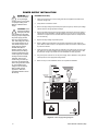
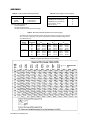
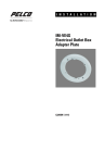
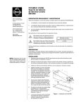
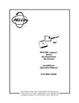
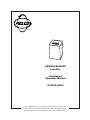
®
LB3000/LB3000PS
Lock Box
Installation/
Operation Manual
C1907M (8/00)
Pelco • 3500 Pelco Way • Clovis, CA 93612-5699 USA • www.pelco.com
In North America and Canada: Tel (800) 289-9100 • FAX (800) 289-9150
International Customers: Tel +1(559) 292-1981 • FAX +1(559) 348-1120
IMPORTANT SAFEGUARDS AND WARNINGS
Prior to installation and use of this product, the following WARNINGS should be observed.
1.
Installation and servicing should only be done by qualified service personnel and conform to all local codes.
2.
Unless the unit is specifically marked as a NEMA Type 3, 3R, 3S, 4, 4X ,6 or 6P enclosure, it is designed for indoor use only and it must not be installed where exposed to
rain and moisture.
3.
The installation method and materials should be capable of supporting four times the
weight of the unit and equipment.
4.
Only use replacement parts recommended by Pelco.
5.
After replacement/repair of this unit’s electrical components, conduct a resistance
measurement between line and exposed parts to verify the exposed parts have not
been connected to line circuitry.
6.
If the unit has fuses, replace fuses only with the same type fuses for continued protection against risk of fire.
The product and/or manual may bear the following marks:
This symbol indicates that dangerous voltage constituting a risk of electric shock is
present within this unit.
This symbol indicates that there are important operating and maintenance instructions
in the literature accompanying this unit.
CAUTION:
RISK OF ELECTRIC SHOCK.
DO NOT OPEN.
Please thoroughly familiarize yourself with the information in this manual prior to installation
and operation.
2
Pelco Manual C1907M (7/00)
DESCRIPTION
The LB3000/LB3000PS Lock Box fastens to a wall to provide a secure enclosure for CCTV
equipment (refer to Figure 1). The LB3000PS includes a 24 VAC power supply that can
power up to 16 cameras (12 vA maximum per camera).
Two locking latches on the front door prevent unauthorized entry.
A monitor can be placed on top of the lock box.
MULTIPLEXER
VCR
STORAGE
SHELF
SHELF FOR
16 TAPES
SHELF FOR
16 TAPES
Figure 1. LB3000/LB3000PS Lock Box
Pelco Manual C1907M (7/00)
3
INSTALLATION
1.
Open the front door of the lock box.
2.
Remove the bottom tape shelf.
3.
Reach inside the lock box and remove the two nuts from the mounting studs on the
bottom of the rear mounting plate (refer to Figure 2).
4.
Remove the mounting plate: pull out a few inches on the bottom of the plate and then
pull downward to release the mounting tabs at the top of the plate.
5.
Place the mounting plate against the wall and mark the eight holes for attaching the
lock box to the wall. The mounting holes on each side of the plate are spaced 16
inches apart so the plate can be fastened to standard wall studs. Also outline the cable
entry opening. Refer to Figure 2.
6.
Drill pilot holes for 3/8-inch diameter wood screws.
7.
Cut out the opening for cable access. Provide 120 or 240 VAC power receptacles for
the following:
VCR
multiplexer
monitor, if it is going to be placed on top of the lock box
MCS16-10 Master Power Supply (LB3000PS only)
8.
Fasten the mounting plate to the wall studs with 3/8-inch diameter wood screws.
9.
LB3000PS Only – Install the MCS16-10 Master Power Supply. Refer to the Power
Supply Installation section.
10. Bring all video cables for the cameras through the opening in the wall. Refer to Table A
in the Appendix for the type of video coaxial cable to use.
It is not necessary to bring any wiring through the wall for the VCR or a monitor placed
on top of the lock box.
If you are going to wire other remote equipment (monitors, alarms, or keyboard) to the
multiplexer, refer to the multiplexer and keyboard manuals for wiring requirements.
LOCK BOX MOUNTING TABS
CABLE ENTRY
MOUNTING
HOLES
POWER SUPPLY
MOUNTING
STUDS
LOCK BOX
MOUNTING
STUDS
Figure 2. Mounting Plate
4
Pelco Manual C1907M (7/00)
11. Fasten the lock box to the mounting plate (refer to Figure 2). Place the top, back side of
the lock box over the mounting tabs on the top of the mounting plate. Open the lock box
door and make sure the mounting studs in the bottom of the mounting plate go through
the stud holes in the bottom of the lock box. Replace the nuts removed in step 3.
12. Replace the bottom tape shelf removed in step 2.
13. Install the VCR and multiplexer. Refer to the manuals supplied with the equipment. Unscrew and remove the access panels in the top and sides of the lock box to reach the
back of the equipment to make wiring/cabling connections.
14. (Optional) Place a monitor on top of the lock box. Connect a video cable to the monitor. Drop the video cable and power cord from the monitor through the round hole in
the top of the lock box. Connect the video cable to the multiplexer and the power cord
to a power outlet.
15. Turn on all equipment and program the VCR and multiplexer according to the manuals
supplied with the equipment.
16. Turn on all equipment and program the VCR and multiplexer according to the manuals
supplied with the equipment.
Pelco Manual C1907M (7/00)
5
POWER SUPPLY INSTALLATION
WARNING: Pelco
shall not be liable
for any damages
resulting from incorrect wiring
or improper loading of the
MCS16-10 Master Power
Supply.
CAUTION: Under
light load conditions
and high power line
input voltage from the utility
company, output voltage from
the power supply (28 VAC
taps only) could exceed 32
VAC. This voltage can cause
over-voltage damage on 24
VAC devices. Keep in mind,
certain devices produce
variable loads (due to
heaters, blowers, and pan
and tilt motion) and during
minimum requirements may
create a light load condition,
causing excessive voltage.
Therefore, Pelco recommends using a 28 VAC tap
only when the supplied wire
size for the given load causes
an unacceptable output
voltage on the 24 VAC tap.
Refer to Table D in the
Appendix to determine
acceptable situations for the
28 VAC tap.
LB3000PS Model Only
1.
Fasten the power supply to the mounting plate with the supplied lock washers and
nuts (refer to Figure 2).
2.
Verify that the on/off switch is OFF.
3.
Remove the high-voltage compartment panel (refer to Figure 3). Set the input voltage
selector switch to the appropriate line voltage.
4.
Remove the spare fuse bag from the high-voltage compartment. The power supply is
shipped with a fuse installed for 120 VAC operation. If you are going to use 240 VAC,
remove the 3-ampere fuse from the fuse holder and replace it with a 1.6-ampere fuse
from the fuse bag.
5.
Replace the high-voltage compartment panel.
6.
Refer to Table B in the Appendix for the number of cameras the power supply can
power. Refer to Tables C and D in the Appendix to determine the size of wire required
to power the cameras.
7.
Install and connect power wires from the cameras to the power supply. For each camera, attach one wire to the COM terminal and the other wire to either the 24V or 28V
terminal (refer to Figure 3). Double-check the installation for safety purposes.
8.
Plug in the power cord and turn on the power supply. Use a voltmeter to verity that the
used outputs are at the appropriate voltage levels.
9.
Return to step 10 of the Installation section to complete the installation.
OUTPUT # 1
(24 VAC)
OUTPUT # 2
(24 VAC)
OUTPUT # 9
(28 VAC)
24V
1
2
3
4
5
6
7
8
9
10
11
12
13
14
15
16
28V
Main Fuse
COM
ON
OFF
Power
OUTPUT 1 THRU 8
OUTPUT 9 THRU 16
Figure 3. Power Supply Wiring Diagram
6
Pelco Manual C1907M (7/00)
APPENDIX
Table B. Power Supply Product Capacity
Table A. Video Coaxial Cable Requirements
Cable Type*
RG59/U
RG6/U
RG11/U
Maximum Distance
750 ft (229 m)
1,000 ft (305 m)
1,500 ft (457 m)
Product
CCD Camera (12 vA maximum)
DF5/DF5S with camera (3 vA)
DF8A/PDF8 (12 vA maximum)
Indoor Spectra® (30 vA)
Esprit™ (50 vA)
* Minimum cable requirements:
75 ohms impedance
All-copper center conductor
All-copper braided shield with 95% braid coverage
MCS16-10
16
16
16
8
4
Table C. Recommended Wiring Distances for Power Supply
The following are the recommended maximum distances (transformer to load) and are calculated
with a 10-percent voltage drop. (Ten percent is generally the maximum allowable voltage drop for
AC-powered devices.)
Input
Voltage
24 VAC
28 VAC
Total vA
Consumed
10
20
30
50
10
20
30
50
20
283 ft
141 ft
94 ft
56 ft
386 ft
193 ft
128 ft
77 ft
(86 m)
(42 m)
(28 m)
(17 m)
(117 m)
(58 m)
(39 m)
(23 m)
Wire Gauge
18
451 ft (137 m)
225 ft
(68 m)
150 ft
(45 m)
90 ft
(27 m)
614 ft (187 m)
307 ft
(93 m)
204 ft
(62 m)
122 ft
(37 m)
16
716 ft
358 ft
238 ft
143 ft
975 ft
487 ft
325 ft
195 ft
(218 m)
(109 m)
(72 m)
(43 m)
(297 m)
(148 m)
(99 m)
(59 m)
Table D. Required Wire Gauge for Power Supply
Pelco Manual C1907M (7/00)
7
SPECIFICATIONS
LOCK BOX
Construction
Cabinet:
Mounting Plate:
Mounting Plate Support:
Finish:
Environment:
Dimensions:
Weight
LB3000:
LB3000PS:
Aluminum
Steel
Steel
Charcoal gray polyester powder coat
Indoor
29.0 (H) x 21.0 (W) x 19.0 (D) inches (73.7 x 53.3 x 48.3 cm)
MCS16-10 POWER SUPPLY (LB3000PS ONLY)
Input Voltage:
120 or 240 VAC, 50/60 Hz
Output Voltage:
24/28 VAC
Outputs:
16
Supply Current:
10 A
Max. Current per Channel:
3A
Required Input Current
120 VAC:
2.20 A
240 VAC:
1.15 A
Surge Protection:
Yes
Output Fuse Rating:
3A
Output Connectors:
Screw-type barrier strips
Output Wire Size:
12-22 gauge, solid or stranded wire
Construction:
Steel
(Design and product specifications subject to change without notice.)
PRODUCT WARRANTY AND RETURN INFORMATION
WARRANTY
Pelco will repair or replace, without charge, any merchandise proved defective in material or
workmanship for a period of one year after the date of shipment.
Exceptions to this warranty are as noted below:
• Five years on FT/FR8000 Series fiber optic products.
• Three years on Genex ® Series products (multiplexers, server, and keyboard).
• Three years on Camclosure ® and fixed camera models, except the CC3701H-2,
CC3701H-2X, CC3751H-2, CC3651H-2X, MC3651H-2, and MC3651H-2X camera models,
which have a five-year warranty.
• Two years on standard motorized or fixed focal length lenses.
If a warranty repair is required, the Dealer must contact Pelco at (800) 289-9100 or
(559) 292-1981 to obtain a Repair Authorization number (RA), and provide the following
information:
1. Model and serial number
2. Date of shipment, P.O. number, Sales Order number, or Pelco invoice number
3. Details of the defect or problem
If there is a dispute regarding the warranty of a product which does not fall under the
warranty conditions stated above, please include a written explanation with the product
when returned.
Method of return shipment shall be the same or equal to the method by which the item was
received by Pelco.
®
• Two years on Legacy , CM6700/CM6800/CM9700 Series matrix, and DF5/DF8 Series
fixed dome products.
• Two years on Spectra ®, Esprit®, ExSite™, and PS20 scanners, including when used in
continuous motion applications.
• Two years on Esprit ® and WW5700 Series window wiper (excluding wiper blades).
• Eighteen months on DX Series digital video recorders, NVR300 Series network video
recorders, and Endura ™ Series distributed network-based video products.
• One year (except video heads) on video cassette recorders (VCRs). Video heads will be
covered for a period of six months.
• Six months on all pan and tilts, scanners or preset lenses used in continuous motion
applications (that is, preset scan, tour and auto scan modes).
Pelco will warrant all replacement parts and repairs for 90 days from the date of Pelco
shipment. All goods requiring warranty repair shall be sent freight prepaid to Pelco, Clovis,
California. Repairs made necessary by reason of misuse, alteration, normal wear, or accident
are not covered under this warranty.
Pelco assumes no risk and shall be subject to no liability for damages or loss resulting from
the specific use or application made of the Products. Pelco’s liability for any claim, whether
based on breach of contract, negligence, infringement of any rights of any party or product
liability, relating to the Products shall not exceed the price paid by the Dealer to Pelco for
such Products. In no event will Pelco be liable for any special, incidental or consequential
damages (including loss of use, loss of profit and claims of third parties) however caused,
whether by the negligence of Pelco or otherwise.
The above warranty provides the Dealer with specific legal rights. The Dealer may also have
additional rights, which are subject to variation from state to state.
RETURNS
In order to expedite parts returned to the factory for repair or credit, please call the factory at
(800) 289-9100 or (559) 292-1981 to obtain an authorization number (CA number if returned
for credit, and RA number if returned for repair).
All merchandise returned for credit may be subject to a 20% restocking and refurbishing
charge.
Goods returned for repair or credit should be clearly identified with the assigned CA or RA
number and freight should be prepaid. Ship to the appropriate address below.
If you are located within the continental U.S., Alaska, Hawaii or Puerto Rico, send goods to:
Service Department
Pelco
3500 Pelco Way
Clovis, CA 93612-5699
If you are located outside the continental U.S., Alaska, Hawaii or Puerto Rico and are
instructed to return goods to the USA, you may do one of the following:
If the goods are to be sent by a COURIER SERVICE, send the goods to:
Pelco
3500 Pelco Way
Clovis, CA 93612-5699 USA
If the goods are to be sent by a FREIGHT FORWARDER, send the goods to:
Pelco c/o Expeditors
473 Eccles Avenue
South San Francisco, CA 94080 USA
Phone: 650-737-1700
Fax: 650-737-0933
REVISION HISTORY
Manual #
C1907M
Date
7/00
Comments
Original version.
Pelco,
thethe
Pelco
logo,
PelcoVision,
Camclosure,
Genex, Legacy,
and Spectra
are registered
trademarks of Pelco.
®
Pelco,
Pelco
logo,
Spectra, Genex,
Legacy,Esprit,
and PelcoVision
are registered
trademarks
of Pelco.
Endura
are trademarks
of Pelco.
™
Espritand
andExSite
Camclosure
are trademarks
of Pelco.
8
©Copyright 2000,
Pelco. 2000,
All rights
reserved.
© Copyright
Pelco.
All rights reserved.
Pelco Manual C1907M (7/00)