1
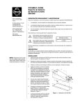
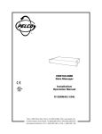
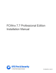
INSTALLATION/OPERATION
®
CM4400/CM4450,
EM4400/EM4450
Ceiling/Wall Mounts
C244M-C (8/04)
Contents
Warnings . . . . . . . . . . . . . . . . . . . . . . . . . . . . . . . . . . . . . . . . . . . . . . . . . . . . . . . . . . . . . . . . . . . . . . . . . . . . . . . . . . . . . . . . . . . . . . . . . . . . . . . . . . . .3
Description. . . . . . . . . . . . . . . . . . . . . . . . . . . . . . . . . . . . . . . . . . . . . . . . . . . . . . . . . . . . . . . . . . . . . . . . . . . . . . . . . . . . . . . . . . . . . . . . . . . . . . . . . . .4
Installation . . . . . . . . . . . . . . . . . . . . . . . . . . . . . . . . . . . . . . . . . . . . . . . . . . . . . . . . . . . . . . . . . . . . . . . . . . . . . . . . . . . . . . . . . . . . . . . . . . . . . . . . . .5
Camera/Enclosure Attachment. . . . . . . . . . . . . . . . . . . . . . . . . . . . . . . . . . . . . . . . . . . . . . . . . . . . . . . . . . . . . . . . . . . . . . . . . . . . . . . . . . . . . . .5
EM4400/CM4400. . . . . . . . . . . . . . . . . . . . . . . . . . . . . . . . . . . . . . . . . . . . . . . . . . . . . . . . . . . . . . . . . . . . . . . . . . . . . . . . . . . . . . . . . . . . .5
EM4450/CM4450. . . . . . . . . . . . . . . . . . . . . . . . . . . . . . . . . . . . . . . . . . . . . . . . . . . . . . . . . . . . . . . . . . . . . . . . . . . . . . . . . . . . . . . . . . . . .5
Specifications. . . . . . . . . . . . . . . . . . . . . . . . . . . . . . . . . . . . . . . . . . . . . . . . . . . . . . . . . . . . . . . . . . . . . . . . . . . . . . . . . . . . . . . . . . . . . . . . . . . . . . . . .6
List of Illustrations
1
2
3
2
Mounting Dimensions . . . . . . . . . . . . . . . . . . . . . . . . . . . . . . . . . . . . . . . . . . . . . . . . . . . . . . . . . . . . . . . . . . . . . . . . . . . . . . . . . . . . . . . . . . . . . . .5
CM4400/CM4450 Dimension Drawing . . . . . . . . . . . . . . . . . . . . . . . . . . . . . . . . . . . . . . . . . . . . . . . . . . . . . . . . . . . . . . . . . . . . . . . . . . . . . . . . . .6
EM4400/EM4450 Dimension Drawing . . . . . . . . . . . . . . . . . . . . . . . . . . . . . . . . . . . . . . . . . . . . . . . . . . . . . . . . . . . . . . . . . . . . . . . . . . . . . . . . . .6
C244M-C (8/04)
Warnings
Prior to installation and use of this product, the following WARNINGS should be observed.
1. Installation and servicing should only be done by qualified service personnel and conform to all local codes.
2. Only use replacement parts recommended by Pelco.
3. Installation shall be done in accordance with all local and national electrical and mechanical codes utilizing only approved materials.
4. Use only installation methods and materials capable of supporting four times the maximum specified load.
5. Use stainless steel hardware to fasten the mount to outdoor surfaces.
6. To prevent damage from water leakage when installing a mount outdoors on a roof or wall, apply sealant around the bolt holes between
the mount and mounting surface.
The product and/or manual may bear the following marks:
This symbol indicates that there are important operating and maintenance instructions in the literature accompanying this unit.
Please thoroughly familiarize yourself with the information in this manual prior to installation and operation.
C244M-C (8/04)
3
Description
The EM4400 wall mount and the CM4400 ceiling mount feature an adjustable tilt table and are designed for use with small camera enclosures.
These mounts are designed to hold loads of up to 15 pounds (6.75 kg).
The EM4450 wall mount and the CM4450 ceiling mount are designed with an adjustable swivel head to handle camera loads up to 7 pounds
(3.15 kg).
4
C244M-C (8/04)
Installation
To install the EM/CM/4400/4450 light-duty mounts, perform the following steps:
1. Drill holes in the mounting surface using the mount as a template, or refer to Figure 1 for mounting dimensions. Where required, drill a 1/2inch minimum diameter hole for cable feedthrough.
2. When applicable, feed the camera power supply cable and coax through the mount arm and out the 1/2-inch diameter hole in the arm. Extra
access may be gained by removing the black plastic cap from the end of the arm. Be sure to feed an adequate quantity of cable through for
camera hook-up.
3. Attach the mount securely using appropriate fasteners.
If you install the mount outdoors on a wall, rain water could leak through the holes for the mounting bolts and damage the wall. This could
be a problem only if the mounting bolts go completely through the wall.
To prevent water damage, seal the bolt holes with an appropriate sealant. Apply the sealant around the bolt holes between the mount and
the mounting surface.
NOTE: The two fasteners that secure the mount to the mounting surface are not supplied.
CAUTION: Make certain that the mounting surface is able to support the full load of the mount, enclosure, and camera.
CAMERA/ENCLOSURE ATTACHMENT
EM4400/CM4400
1. Attach the camera or enclosure/camera assembly using one or both of the 1/4-20 x .500 hex head screws provided.
2. Loosen the hex head bolts securing the tilt table assembly and adjust for the proper pan and tilt angles. Tighten all hardware (access to the
pan adjustment screw is gained by removing the black plastic end cap).
3. Connect camera power and coax cable. Reference the appropriate enclosure manual (as required) for further installation.
EM4450/CM4450
1. Attach the camera or enclosure/camera assembly to the 1/420 threaded stud on the swivel head and tighten the nut
against the camera.
2. Loosen the set screw on the swivel assembly, if necessary,
with the Allen wrench that is provided. Position the camera/
enclosure in the desired position and tighten the set screw.
3. Connect camera power and coax cable.
Figure 1. Mounting Dimensions
C244M-C (8/04)
5
Specifications
Pan Adjustment
Unlimited 360°
Tilt Adjustment
±90°
Locking Method
CM/EM4400
1/4-20 hex head bolts (3X)
CM/EM4450
Set screw secures swivel assembly
Enclosure/Camera
Mounting
CM/EM4400
Two 1/4-20 hex head screws provided
CM/EM4450
1/4-20 threaded stud and nut
Maximum Load
CM/EM4400
15 lb (6.75 kg)
CM/EM4450
7 lb (3.15 kg)
Construction
Steel
Finish
Gray polyester powder coat
Dimensions
See Figures 2 and 3
Unit Weight
CM4400
3.62 lb (1.64 kg)
CM4450
1.35 lb (0.61 kg)
EM4400
2.70 lb (1.22 kg)
EM4450
2.34 lb (1.06 kg)
(Design and product specifications subject to change without notice.)
.25 x .44 SLOT
(.64 X 1.12)
Ø .50 (1.27)
2.00
(5.08)
2.00
(5.08)
3.63
(9.22)
5.13 (13.03)
2.00
(5.08)
1.00
(2.54)
10.00
(25.40)
2.68
(6.81)
6.00
(15.24)
2.00
(5.08)
1.00
(2.54)
CM4400
CM4450
NOTE: VALUES IN PARENTHESES ARE CENTIMETERS;
ALL OTHERS ARE INCHES.
Figure 2. CM4400/CM4450 Dimension Drawing
Ø .50 (1.27)
.25 x .44 SLOT
(.64 X 1.12)
2.00
(5.08)
7.63 (19.38)
9.13 (23.19)
2.00
(5.08)
1.00
(2.54)
3.00
(7.62)
2.68
(6.81)
2.00
(5.08)
5.00
(12.7)
3.25
(8.26)
1.00
(2.54)
EM4400
10.00 (25.40)
EM4450
NOTE: VALUES IN PARENTHESES ARE CENTIMETERS;
ALL OTHERS ARE INCHES.
Figure 3. EM4400/EM4450 Dimension Drawing
6
C244M-C (8/04)
PRODUCT WARRANTY AND RETURN INFORMATION
WARRANTY
Pelco will repair or replace, without charge, any merchandise proved defective in material or
workmanship for a period of one year after the date of shipment.
Exceptions to this warranty are as noted below:
• Five years on the following fixed camera models: CC3701H-2, CC3701H-2X, CC3751H-2,
CC3651H-2X, MC3651H-2, and CC3651H-2X.
• Three years on all other fixed camera models (including Camclosure® Integrated Camera
Systems) and Genex® Series (multiplexers, server, and keyboard).
If a warranty repair is required, the Dealer must contact Pelco at (800) 289-9100 or
(559) 292-1981 to obtain a Repair Authorization number (RA), and provide the following
information:
1. Model and serial number
2. Date of shipment, P.O. number, Sales Order number, or Pelco invoice number
3. Details of the defect or problem
If there is a dispute regarding the warranty of a product which does not fall under the
warranty conditions stated above, please include a written explanation with the product
when returned.
• Two years on all standard motorized or fixed focal length lenses.
Method of return shipment shall be the same or equal to the method by which the item was
received by Pelco.
• Two years on Legacy®, CM6700/CM6800/CM8500/CM9500/CM9740/CM9760 Matrix,
DF5 and DF8 Series Fixed Dome products.
RETURNS
• Two years on Spectra®, Esprit®, and PS20 Scanners, including when used in continuous
motion applications.
In order to expedite parts returned to the factory for repair or credit, please call the factory at
(800) 289-9100 or (559) 292-1981 to obtain an authorization number (CA number if returned
for credit, and RA number if returned for repair).
• Two years on Esprit® and WW5700 series window wiper (excluding wiper blades).
• Eighteen months on DX Series digital video recorders and NVR300 series network video
recorder.
• One year (except video heads) on video cassette recorders (VCRs). Video heads will be
covered for a period of six months.
• Six months on all pan and tilts, scanners or preset lenses used in continuous motion
applications (that is, preset scan, tour and auto scan modes).
Pelco will warrant all replacement parts and repairs for 90 days from the date of Pelco
shipment. All goods requiring warranty repair shall be sent freight prepaid to Pelco, Clovis,
California. Repairs made necessary by reason of misuse, alteration, normal wear, or accident
are not covered under this warranty.
Pelco assumes no risk and shall be subject to no liability for damages or loss resulting from
the specific use or application made of the Products. Pelco’s liability for any claim, whether
based on breach of contract, negligence, infringement of any rights of any party or product
liability, relating to the Products shall not exceed the price paid by the Dealer to Pelco for
such Products. In no event will Pelco be liable for any special, incidental or consequential
damages (including loss of use, loss of profit and claims of third parties) however caused,
whether by the negligence of Pelco or otherwise.
The above warranty provides the Dealer with specific legal rights. The Dealer may also have
additional rights, which are subject to variation from state to state.
All merchandise returned for credit may be subject to a 20% restocking and refurbishing
charge.
Goods returned for repair or credit should be clearly identified with the assigned CA or RA
number and freight should be prepaid. Ship to the appropriate address below.
If you are located within the continental U.S., Alaska, Hawaii or Puerto Rico, send goods to:
Service Department
Pelco
3500 Pelco Way
Clovis, CA 93612-5699
If you are located outside the continental U.S., Alaska, Hawaii or Puerto Rico and are
instructed to return goods to the USA, you may do one of the following:
If the goods are to be sent by a COURIER SERVICE, send the goods to:
Pelco
3500 Pelco Way
Clovis, CA 93612-5699 USA
If the goods are to be sent by a FREIGHT FORWARDER, send the goods to:
Pelco c/o Expeditors
473 Eccles Avenue
South San Francisco, CA 94080 USA
Phone: 650-737-1700
Fax: 650-737-0933
REVISION HISTORY
Manual #
C244M-C
Date
8/04
Comments
Removed agency logos from cover and updated specifications; updated Warranty and Return information.
Pelco, the Pelco logo, Spectra, Genex, Esprit, Camclosure, and Legacy are registered trademarks of Pelco.
© Copyright 2004, Pelco. All rights reserved.
®
Worldwide Headquarters
3500 Pelco Way
Clovis, California 93612 USA
USA & Canada
Tel: 800/289-9100
Fax: 800/289-9150
International
Tel: 1-559/292-1981
Fax: 1-559/348-1120
www.pelco.com
ISO9001
United States | Canada | United Kingdom | The Netherlands | Singapore | Spain | Scandinavia | France | Middle East