1
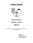
USER GUIDE
DM Engineering
Multi Station Relay Adapter
(MSRA and MSRA-RM)
Version 1.36
DM Engineering
2174 Chandler St.
Camarillo, CA 91345-4611
805-987-7881 800-249-0487
www.DMEngineering.com
Overview:
The DM Engineering Multi Station Relay Adapter (MSRA) is a microprocessor
based, three stereo channel switching accessory for the Sage and Digital Alert
Systems DASDECTM EAS encoder-decoders, when used in the analog audio
configuration that expands the allowable controlled number of stations to a total of
four from a single EAS Encoder-Decoder. The MSRA is available in both a table top
version and a 2U rack mount version (MSRA-RM). Both the Sage and DASDECTM
encoder/decoders, (referred to as endec) have embedded programming that
allows additional stereo or mono stations, in addition to the station controlled within
the endec itself, to be controlled using Multi Station Relay devices such as the DM
Engineering MSRA. All digital commands and EAS audio are supplied by the endec,
and the MSRA interprets these commands to select the appropriate station or
stations for EAS broadcast.
Digital control communications between the endec and the MSRA is accomplished
via the supplied DB9 to RJ11 cable. Connection to the DASDECTM is made at the
main serial port, and for the Sage through either the COM 4 or COM 5 (1200 baud)
ports on the Model SE1822, and on any port on the 3644 Digital when programmed
to do so. (See the Sage Programming procedure below.)
DASDECTM programming may be implemented by following the Digital Alert Systems
Application Note # APNDAS-0139. The direct link to this PDF document is:
http://www.digitalalertsystems.com/pdf/apndas-0139.pdf .
EAS audio for the MSRA is derived from the DASDECTM Auxiliary 3.5mm green jack
on the lower right rear insert panel of the unit, or from the “Speaker Line Output”
(SE-1822) or “Line Out” (3644 Digital) connection on the rear of the Sage. A multiturn recessed front panel “ Input Gain” trim potentiometer and individual multi-turn
“Station Gain” controls on the MSRA are provided for controlling the active stereo
distribution amplifier sections having balanced output levels capable of greater than
+12dBm into a 600 ohm load impedance. A recessed front panel “Test” switch is
also provided for aiding the setup of the audio levels. (See Audio Setup procedure
below)
An optically isolated open emitter and collector “Tally” output is provided for user
interface and is active when any or all of the 3 MSRA controlled stations are
activated, and remains active until the end of the EAS activation.
The MSRA is transparent to program audio due to it’s loop-through design, and uses
6 high quality bifurcated gold over silver nickel contact sealed relays, one relay for
each left and each right channel circuit. The MSRA also is designed to remain
transparent to program audio during a power failure condition.
All station inputs and outputs are connected using large 5mm Eurostyle screw type
pluggable connectors for wiring ease and connection reliability. The internal power
supplies, precision regulators, precision audio distribution amplifier sections and
quality components throughout assure long life and trouble free operation of the
MSRA. No external power supplies (wall warts) are required. Front panel LED
indicators are provided for “Power” and “Station” left and right audio relay activation
2
during an EAS event. The MSRA is internally protected by a 1/4A AGC type fast
blow fuse.
Installation:
1.
The MSRA should be located in an area that is not subjected to
temperatures in excess of 85 degrees centigrade, nor subjected to moisture
greater than 90% relative humidity, non-condensing.
2.
Station audio connections are made using the pluggable Eurostyle
connectors. Wires should be stripped approximately ¼ inch and fully
inserted into the connector. Assure that the connector locking screws are
fully tightened and that the wires are secure. The MSRA insertion in the
station audio chain should be made between the stations main audio source
and the input to the stations processing equipment. Balanced input and
output (+ and -) connections are made for each applicable station audio
chain for both the left and right channels as indicated on the MSRA. It is
important that at no time should any of the + or – outputs be connected to
ground. Grounding any of the active outputs for an extended period of time
may cause damage to the individual amplifier IC and will not be covered
under the MSRA warranty.
3.
RF protection is incorporated within the MSRA, but in some high RF
environments it may be advisable to connect a lead from any of the MSRA
station “Ground’ terminals to your station ground.
4.
Data and audio connections are made using the supplied Data/Audio RJ11
Modular to DB9/audio cable. Data connection to the DASDECTM is made at
the main serial port, or is connected to the Sage 1200 baud COM4 or COM5
ports (SE-1822) or any properly programmed COM port on the 3466 Digital.
(See Sage Programming section below). The RJ11 modular connector is
connected to the MSRA Data/Audio input port. For long distance runs
between the MSRA and the Endec, the use of CAT5e cable is
recommended for the extended run. Both audio and data may be sent
using CAT5e cable except in high RF environments where a separate
shielded pair should be used for the audio. (See drawing below for the
Interface Cable Schematic.)
5.
The audio connection is made by connecting:
3
a. Sage: the red audio wire from the DB9 connector to the “Speaker
Line” (SE-1822) or “Line Out” connection (3644 Digital) and the black
wire to any of the “Audio Common” or “Gnd” connections. Audio levels
are set according to the “Audio Set-up” section below.
b. DASDECTM: Using the 3.5mm plug to screw terminal adapter, connect
the red audio wire from the DB9 connector to the “red wire” screw
terminal and the black wire to the “black wire” terminal. The plug is
inserted into the green jack on the lower right rear insert panel of the
unit.
DASDECTM Interface Schematic
6.
The “Tally” output is not required to be used for proper operation of the
MSRA. It consists of an optically coupled open collector/emitter NPN
transistor for external signaling that is active when any or all of the MSRA
relays are activated. The transistor can dissipate 150mw at 30 volts
maximum, emitter to collector. The collector connection is designated by a
“+” symbol, the emitter by a “–“ symbol.
7.
The MSRA is connected to the 120VAC mains via the 2 prong 6 foot AC
cord.
Set-up and Operation
A. DASDECTM Programming: Programming may be implemented by following
the Digital Alert Systems Application Note # APNDAS-0139. The direct link to
this PDF document is: http://www.digitalalertsystems.com/pdf/apndas0139.pdf .
B. Sage Programming: Reference section 9.2(SE-1822) or section 10.2 (3644)
of the Sage User Guide and Reference Manual for complete details. Entry of
a password will be required to complete most of the steps below.
Do not reassign any of the MSRA relays to stations using the msrp.assign
msrp relay menu unless you are positively sure of what you are doing. The
default settings are the proper settings for most installations.
Just in case, the default settings for relay assignment are:
Relay 1L & 1R
Relay 2L & 2R
Relay 3L & 3R
Station 2
Station 3
Station 4
4
Relay 4L & 4R
1.
2.
3.
4.
5.
Station 0
Assign either COM4 or COM5 (1200 baud) ports on the SE-1822, or any
port on the 3644 Digital to be used as a RELAY device for using the MSRA.
(menu.devices.COM”X”.device type.relay) X=selected COM port.
For the 3644 Digital it will be necessary to set the baud rate to 1200 baud
for the COM port chosen by using: (menu.devices.COM”X”.baud rate)
X=selected COM port.
Set up the call sign for each station by using: (menu.MSRP.station #. call
sign). The # character is the station number 2-4. Follow the prompts to
install the desired station call signs for stations 2-4.
Enable each station desired by setting: (menu.MSRP.station #.enable) to
“YES” for each desired station.
The 3644 Digital Endec is shipped with the digital audio enabled by default.
It will be necessary to disable the digital audio. This may be done from
the endec front panel by setting: (menu.digital audio) and select “NO” at
the prompt to disable digital audio, or by selecting the software program
Endecsetd digital audio tab and disabling the digital audio. You may be
asked to re-boot the endec and you will need to recycle the endec power for
the changes to take effect. See section 4.5.4 of your 3644 manual for
details.
C. Audio Set-up
1. Sage: The MSRA EAS audio output is factory set at unity gain to deliver a 10dBm output into 600 ohms with the Sage Attention and/or Data Tone gain
levels set at the default value of 32 (-10dBm).
2.
DASDECTM: The “Aux” output must be enabled and the right and left
“Auxiliary” levels should be set to 58 (-10dbm). This is done by accessing
the software “Setup Audio” tab and going to the “Audio Output Levels/Tests”
section and scrolling to the “Aux 1” sub menu. You may preview the tones
from this menu. To actually test an RWT see section 8-b below.
3.
The MSRA factory settings may be required to be readjusted after initial setup of the endec. The user should set the endec EAS “Attention Tone” and
“Data Tone” modulation levels to achieve a minimum of 80% modulation on
all stations and the Attention and Data tones should be balanced to within 1
dB, left and right channels, to be in compliance with Part 11 of the FCC
Rules. The MSRA relies on these tones to be balanced as the precision
distribution amplifier sections will faithfully reflect this balance or imbalance.
Refer to section 4.3 (SE1822) or 4.4 (3644) of the Sage User and
Reference Guide for detailed instructions or section 4.6.1 of the DASDECTM
Instruction Manual.
4.
After initial audio set-up of the endec as described above has been
completed for Station 1, and the proper modulation levels and balance have
been achieved, the individual “Station Gain” controls may need to be
adjusted on the MSRA to achieve a minimum of 80% modulation when an
attention tone is transmitted. Each “Station Gain” control simultaneously
5
adjusts both left and right levels of the balanced precision MSRA amplifiers
as detailed below.
5.
To generate an attention test tone on the Sage for setting the audio levels in
the MSRA enter (menu.levels.attn tone). You will be prompted to choose
which relays are activated for audio set-up. Pressing and holding the
recessed “Test” button on the MSRA will activate stations 2-4 relays
simultaneously to aid in audio level set-up. Note: Do not arbitrarily change
the levels on the endec itself as they may have been previously been set for
the correct levels for station 1. To end the test tones press done or abort.
6.
Generating attention test tones on the DASDECTM is done by accessing the
software “Setup Audio tab and going to the “Audio Output Levels/Tests”
section and selecting the “Aux 1” sub menu. Note: Do not arbitrarily change
the levels on the DASDECTM itself as they may have been previously been
set for the correct levels for station 1.
7.
If the endec audio outputs have been significantly increased beyond the 10db value, the MSRA output waveform of any one channel of any of the
station outputs should be checked using an oscilloscope to assure that the
input stage is not being overloaded. Overloading will be noted by observing
any clipping of the MSRA output waveform while testing. Adjustment of the
“Input Gain” trimmer potentiometer may be required to avoid clipping. This
control has limited effect on the input gain stage and is designed for only
reducing an overloaded input condition or increasing all three MSRA outputs
simultaneously if required. Set the appropriate “Station Gain” multi-turn
potentiometers to get the desired modulation levels for each station.
8.
Final testing of the system may be done by generating an RWT by entering:
a. Sage: (week. your password.STN). Follow the (yes-no) prompts
to test any or all of the stations, 1-4 and then (proceed).
b. DASDECTM: The DASDEC II supports configuration of a static set of
Required Weekly test parameters on the Setup > Encoder >
Required Tests page. Once configured, the Encoder > Send Alert >
One-Button Alert page presents a single button for issuing the weekly
test alert. This feature simplifies sending a weekly test alert to a single
action. See section 6.1.2 of the DASDECTM Manual.
Specifications:
Loop-through Frequency Response:
Loop-through Signal to Noise:
Loop-through Channel Separation:
EAS Audio Input:
EAS Audio Output:
Switching Relays (loop-through):
DC to 20 kHz, +/- .1dB
>80dB
>80 dB
-10 to +10 dBm
-10 to +12 dBm
Sealed, with bifurcated gold clad over
silver nickel contacts, 2 per stereo channel
6
Logic Control:
Logic and audio I/O Interface:
Status Indication:
Power Requirement:
Size:
Optional Rack Mount:
8 bit PIC Microprocessor
RJ11 modular to DB9 RS232 (Logic) and
wire leads, 3.5mm jack adapter (audio)
Front Panel LED Power and EAS Station
Relay Active indicators
105-125VAC, 50-60Hz (internally fused at
1/4 A)
9 X 6X 2 3/8 inch ABS cabinet
MSRA-RM (1 MSRA on one 2 unit high
19” panel),
Warranty Information:
The DM Engineering MSRA and is warranted for a period of one year from the date
of purchase. This warranty covers materials and workmanship only. Any
misapplication, physical or electrical damage from outside sources or by the
customer is not covered. The customer must pay shipping costs to the factory, and
DME will pay shipping costs to return the warranted equipment to the customer. Any
priority shipping costs are to be the responsibility of the customer as ground service
is standard. Please contact the factory for an RMA number prior to any returns.
Items returned without an RMA may be sent back to the customer unopened.
Technical Support
If you have questions, experience difficulties with the product or require further
information please contact DME at: 805-987-7881, toll free 800-249-0487, or E-mail
technical support at: [email protected], or visit www.dmengineering.com
for the latest User Guide.
DASDECTM technical support is available by calling 585-765-1155 and selecting
“Technical Support” from the main menu.
7