1
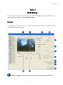
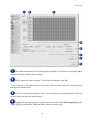
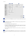
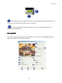
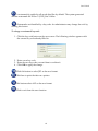
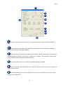
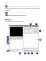
X3 Series DVR
User's Manual
Please read this manual before using your new DVR and retain it for future reference.
General Information
ii
General Information
Table of Contents
Welcome and General Instructions
Safety Precautions ..................................................................................................................... 1
Limitation of Warranty ............................................................................................................. 2
Service Information................................................................................................................... 2
Unpacking.................................................................................................................................. 2
Overview.................................................................................................................................... 3
Logging In.................................................................................................................................. 3
DVR Setup......................................................................................................................................... 4
Camera ....................................................................................................................................... 4
Recording Frame ....................................................................................................................... 7
Scheduler.................................................................................................................................... 9
I/O ............................................................................................................................................ 12
Intensive Recording ................................................................................................................ 13
Save Drive ................................................................................................................................ 16
Network ................................................................................................................................... 18
Voice Alert ............................................................................................................................... 20
User........................................................................................................................................... 22
Other......................................................................................................................................... 24
Audio 1..................................................................................................................................... 26
Video Out................................................................................................................................. 27
Email......................................................................................................................................... 28
POS (Point of Sale) .................................................................................................................. 30
Monitoring Mode ............................................................................................................................. 33
Monitoring Window ............................................................................................................... 33
Camera View Panes ................................................................................................................ 37
PTZ Controller......................................................................................................................... 38
Instant Recording .................................................................................................................... 41
E-Map ............................................................................................................................................. 43
Search Mode .................................................................................................................................... 47
Time Table................................................................................................................................ 48
Special Searches....................................................................................................................... 50
Real Player ............................................................................................................................... 50
Multi Time Player.................................................................................................................... 51
Day Search ............................................................................................................................... 52
Object Search............................................................................................................................ 53
Using the Playback Controls .................................................................................................. 55
Playback Status........................................................................................................................ 57
Saving Data.............................................................................................................................. 58
Backup ............................................................................................................................................ 61
Instant Backup ......................................................................................................................... 61
Scheduled Backup ................................................................................................................... 64
iii
General Information
Viewers ........................................................................................................................................... 68
Single Viewer........................................................................................................................... 68
Image Viewer........................................................................................................................... 69
POS Viewer .............................................................................................................................. 71
Updates........................................................................................................................................... 74
iv
Welcome
Thank you for choosing an X3 DVR Digital Video recorder. Please read all the
safety and operating instructions in this manual before operating the system. This
manual guides you through installing and using the X3 DVR program.
If you are a first time user of the X3 DVR, you should read this manual carefully
and follow the instructions even if you are familiar with similar products. If you
have questions, please contact your local authorized X3 DVR dealer or certified
installer.
Safety Precautions
Precautions
Power and Voltage:
•
•
•
•
Disconnect power from the DVR before installation.
Check power supply voltage and adjust if necessary.
If unstable power conditions exist, use a stable adapter to prevent system
malfunction.
Allow plenty of room for cables and provide support if cables are heavy.
Magnetic or Electric Fields:
•
•
•
Keep the system away from magnetic devices and avoid impacts to the case.
Do not place the product near any wireless devices such as radios or TVs.
Keep at least 20 cm away from other electronic equipment.
Dust and Moisture:
•
•
•
•
Do not block the system ventilation ports on the DVR case.
Do not expose the product to rain, extreme humidity, or dusty environments.
Install a dehumidifier if humidity is extreme.
Use compressed air to clear air intake filter, fan, and major part of the system every
three (3) months.
Extreme Change of Temperature
•
Do not expose the product to direct sunlight, heating appliances, or extreme cold.
DVR Setup
Limitation of Warranty
We warrant that the X3 DVR series is free from defects in materials and workmanship
under normal use and service for all parts excluding hard drives for a period of one year
from the date of purchase.
If a defect occurs, contact your authorized dealer for further instructions. This warranty
does not apply to repairs or replacements necessary due to any cause listed here:
1. Improper installation
2. Acts of nature
3. Accident
4. Misuse
5. Lack of proper maintenance
6. Voltage fluctuations
7. Unauthorized repair or modifications
8. Virus issues or spam
9. Other third party software
10. Overheating
Service Information
1. To avoid additional defects, do not attempt to repair this unit by yourself. Please
contact your authorized dealer or certified installer for a service technician.
Unauthorized repairs void the warranty and may result in fire, electrical shock, or
other hazards.
2. All shipments for repair must be prepaid and properly packed in the original
packing with a note describing the defect.
3. Send the product with RMA number and other related documents obtained from
Ascendent Technology Group, Inc., or its agent as proof of purchase of the product.
Unpacking
Remove the DVR from the packaging and place it careful on a flat, clean surface. Before
installation, make sure all the parts listed below are included:
2
DVR Setup
1.
2.
3.
4.
5.
6.
7.
Software CD
DVR System
Key
Mouse
Keyboard
Power Cable
Instruction Manual
Overview
The X3 security system consists of cameras, sensors, the digital video recorder (DVR), a
monitor, and software.
This manual covers the use of X3 DVR Site, Ascendent Technology Group’s software
program. This includes setup, monitoring, recording data, backup, and data retrieval.
Please read these instructions carefully before using your X3 DVR system.
In this manual, click and drag always mean using the left mouse button unless the right
mouse button is specified in the text.
Logging In
You must log in to access the system. Select Start > Login. The log in window appears.
Enter your user name and password as assigned by the system administrator. The default
login is User Name: Administrator and Password: 1234. You can change this password
when you set up the system.
3
DVR Setup
Section 1
DVR Setup
When the system is started for the first time, the DVR Setup appears automatically. You
can access it at any time by selecting Start > Setup.
Camera
The Camera window allows you to set up each camera individually. All camera functions
are enabled from this window.
Camera #1 appears by default; select another camera from the drop-down list.
4
DVR Setup
The current view of the camera and the resolution (image size) appear here.
The name of the selected camera.
To change the camera name:
1. Select and delete the existing name.
2. Type in a descriptive name. Often cameras are named for their location.
Click this button to select the color of the text in the camera view window. A standard
Windows color chooser window appears. Select the color you want and click OK.
Use this section to set up motion detection regions in the camera view.
Note: To set up motion detection, you must set the recording mode to Motion in the
Scheduler and a minimum of 1 frame must be set in the Rec. Speed. See Scheduler on page
9.
To set up a motion detection region:
1. Click Show region to see the motion detection regions on screen.
2. In the camera view window, drag the mouse to make a motion detection region. A
colored window with a motion region number appears. You can make up to five
regions in the view.
3. Mark all sets the entire camera view as a motion detection area.
4. Click Beeping if you want the system to alert you with a beep when motion is
detected.
5. Drag the slide bar to adjust the sensitivity of the motion detection.
To erase a motion detection region:
5
DVR Setup
1. Click on the region you want to erase and press the Delete key on your keyboard.
You can also drag the region out of the camera view window.
2. To erase all the motion detection areas, click the Erase All button.
The Intelligent Camera Move Away Detection section lets you setup how the system
reports that a camera has been disabled in some way.
•
Click Message Box to have the system display a message on screen.
•
If you select Message Box, you can also select Beep. This makes the system give you
an audible alert when the message box appears on screen.
•
Click Control 01 to use that control instead of a message box.
•
Drag the slide bar to adjust the sensitivity of the detection.
The Full Screen section sets the length of time the camera view appears full screen
when this camera detects motion or a sensor is triggered.
•
Check Motion or Sensor to activate full screen mode.
•
Select the length of time in seconds that the full screen appears. Sixty seconds is the
maximum setting.
In order to use PTZ Setup, this camera must be equipped to pan, tilt, and zoom.
•
PTZ: Select the model of the PTZ camera.
•
The DVR communicates with the camera at this Baud rate. Refer to the camera
documentation to determine the baud rate it supports.
•
Select the PTZ Protocol. Refer to the camera documentation to determine the
protocol the camera supports.
•
Set the Address of the PTZ camera. This is set on the camera using DIP switches.
6
DVR Setup
Click Default to return all settings to factory default.
Click All to apply these settings to all the cameras.
Click Apply to save these settings.
Click Close to exit from this window.
The Alarm Frame Setting determines how long the DVR will record before and after
motion is detected or a sensor is triggered. The system can recapture and record up to 30
seconds of what the camera viewed before the incident, and up to 180 seconds (three
minutes) afterward. This prevents the system from being circumvented by moving very
slowly or holding still.
Select the length of time from the drop-down lists.
Use the Color Setting section to adjust the brightness, hue, and contrast of the camera
view.
Recording Frame
The settings in the Recording Frame window govern the image size and resolution of the
camera views. This also determines how much of the system capacity each camera uses.
7
DVR Setup
Put a check in a box to select a camera. Changes you make to the settings apply to
the selected camera.
The remaining columns in this table summarize the settings you make in this window for
all cameras on the system.
The number of the camera selected.
The name of the camera selected.
Image Setting determines the size and resolution of the camera view on the DVR
monitor.
CIF is the standard 352 x 240 image resolution. Half is two CIFs, or 724 x 240, and Full is
four CIF units with a 720 x 480 image size.
•
Drag the slide bar to determine the number of frame blocks for the image. Keep in
mind the limits of the total system. In the example shown, the system has a limit of
8
DVR Setup
120 frame blocks. By assigning 30 to this camera, one quarter of the system capacity
is consumed by this single camera.
•
Drag the slide bar to set the image quality for this camera. The image quality
required may vary with the area the camera watches. A camera guarding a cash
register may require very high resolution, while one watching a parking lot may not.
Check this section for information about the camera settings.
NTSC is the standard image type used in North America for 120 volt systems.
The Frame number compared to the total system and the number of Frame blocks in
relation to the system capacity are shown here.
Note: If a camera is set to CIF resolution the frame blocks will be the same as the recording
frame rate. HALF resolution will use two frame blocks for each recorded frame. FULL
resolution will use four frame blocks for every recorded frame.
Click Default to return all settings to factory default.
Click Apply to save these settings.
Click Close to exit from this window.
Scheduler
Use this window to determine when each camera is recording and what recording mode it
is using.
9
DVR Setup
These buttons indicate the recording modes available. C is continuous recording, M is
motion recording, and N is no recording.
Click a button to select a camera. To select all the cameras, click All.
To set a camera to the same mode for the entire 24 hour period, click the Camera button
and then the mode button.
The 24 one hour time periods of a day. To set the mode for a particular hour, click on
an hour block and then the mode button.
To apply the time settings for a specific day of the week, click Select single day in the
Apply Day(s) section below, and then click a button to select a day.
10
DVR Setup
Determines how many days the schedule applies to.
•
Click Select single day and then select a day to apply the schedule to one day of the
week.
•
Click Select multiple days to apply the schedule to more than one day. You may
click as many day buttons as needed.
•
Click Special day setting if the schedule applies to a holiday or event day. If you
choose this setting, proceed to the Special day settings.
Use this section to select the special days that require their own schedule.
•
Click Add to access a calendar and select the holiday or event days. The calendar
shows the current month. Click the single arrow to advance one month, or the
double arrow to advance a year. Double click a date to select it. A red circle appears
on the date and the calendar closes.
•
To remove a date, select the item in the list and click the Delete button.
Click Apply to save these settings.
Click Close to exit from this window.
11
DVR Setup
I/O
The sensors on your system. These sensors trigger recording on the camera they are
assigned to. A checkmark activates the sensor.
NO/NC indicates the normal condition of the sensor. A money trap is an example of
a sensor that is normally open (NO). When it closes, it makes the camera record the
incident.
Normally closed (NC) sensors include window tape and magnetic catches on doors. These
sensors cause the system to record when they are opened.
12
DVR Setup
Assign the sensor to a camera by selecting it from the drop-down list.
The controls for the sensors. A control is a relay output that can be triggered by a sensor
input or by a camera sensing motion. Place a checkmark to activate the control. Select the
duration in seconds from the drop-down list.
Use this section to map the controls to the sensors. Select the sensor number from the
drop-down list and check the control that should be assigned to it.
This section determines the output when a camera detects motion. Check the control
that should apply.
Click this button to apply the settings on this window.
Click Close to exit from this setup window.
Intensive Recording
Use this function to record at a high frame rate when a camera is triggered by a sensor or
motion.
Note: To apply this function, set the recording mode to M in the Scheduler. See Scheduler on
page 9.
13
DVR Setup
The recording configuration you are setting up. You can set up to four different
configurations.
Check Enable Intensive Recording to activate the process.
•
Select the camera that should record intensively.
•
Select the length of time in seconds that the camera should record intensively.
•
Check Enable on Sensor to start intensive recording when a sensor is triggered.
Select the sensor number with a checkmark.
•
Check Enable on Motion to start intensive recording when a camera detects motion.
•
Set the Frame rate of the camera with the slide bar. The maximum setting is 30
frames per second.
14
DVR Setup
•
The total number of frames on the system and the number dedicated to intensive
recording are shown at the bottom.
Use this section to reduce the recording rate for other cameras while a single camera
is recording intensively. This is necessary because intensive recording consumes so much
of the system’s total capacity, the remaining cameras must record at a reduced rate during
the intensive recording period.
•
Select the maximum frame rate using the slide bar. The maximum setting is seven
frames per second.
•
Select the minimum frame rate.
Click this button to apply all the settings in this window.
Click this button to close the window.
15
DVR Setup
Save Drive
Use this window to view and manage the hard disk drives on the system.
Hard Drive Information displays detail information on the hard disk drive and other
backup devices installed on your system.
•
The Installed Drive List shows all the saving devices installed.
•
Name lists the drives by name, normally a letter.
•
Type indicates what the drive is, whether a hard drive, DVD drive, or other type.
•
The Serial Number of a hard drive is assigned when the drive is formatted.
•
Mode indicates the current working status of the drive.
o System: The drive where the operating system (OS) is installed.
16
DVR Setup
o DVR: The drive where the DVR software is installed.
o Reserved: This drive is capable of saving images but is not enabled at this time.
o Working Off: This drive is ready to save data.
o Working On: The drive is currently saving data.
o Free: A drive that is not assigned to saving or backing up data.
These buttons permit you to add a drive to the list of hard drives. Select a drive in the
list and click the Plus (+) button. To remove a drive from the Save list, select and click
Minus (-). Double clicking a drive will do this as well, if you double click a drive in the
save disk list it will move to the installed drive list, and vice versa.
In this list, an O indicates the drive is currently saving data.
If you have only one hard drive on your system, all data is recorded to that drive. If you
have more than one hard drive, you can determine which one is recorded to first.
To set up the first save drive:
1. In the Installed Drives list, select the drive you want to record to first. The drives
that host the OS and the DVR program cannot be selected.
2. Click the Set Starting Drive button.
3. Click Apply to apply the changes.
4. A format save box appears, asking permission to format the drive. Click Yes to
confirm that you want to format the drive.
WARNING!
Formatting destroys all existing saved image data on the drive.
5. Another dialog box appears. Click Yes to save your setting and restart the computer
after formatting is complete.
6. Click Apply to begin formatting the drive. The computer restarts afterward.
17
DVR Setup
Note: After the computer reboots, return to this page and make sure the correct drive is
selected. If it is not, repeat these steps again.
Drive Status shows you the amount of free and used space on the drive selected in
either of the lists. The pie chart is a quick reference, indicating the ratio of used to free
space and the percentage of each.
This section shows the used and free space on the drive as numbers.
Click the Formatting button to format the selected drive. Formatting destroys all data
that has been saved to the drive. The drive with the System and DVR mode cannot be
formatted.
Click this button to apply all the settings in this window.
Click this button to close the window.
Network
Use the Network window to setup access across a network. If your system is not part of a
network, this setup does not apply to you.
18
DVR Setup
The system locates its IP Address automatically. This address defines its place on the
network.
Central Management Software (CMS) is an additional software package that allows
central monitoring of the system.
•
Check Allow Remote Access to begin the setup.
•
No response waiting time from CMS adjusts the length of time the local system
should wait for a response from central monitoring. The minimum is 10 seconds,
with a maximum of 120 seconds (2 minutes).
•
Server Port Setup determines which port the server will use to transfer data or
stream video.
Remote Access Software (RAS) allows the local system to be accessed by modem
across the Internet. This additional software permits the system to be monitored from any
location.
19
DVR Setup
•
Enter the user name and password that must be entered to access the local system.
•
Enter the IP address of the server that is permitted to access the system. Free for all
IP does not restrict the IP address, and may be necessary if the system does not have
static IP addresses.
•
Central Alarm Monitoring Software (CAMS) is an extra software package. Your
dealer supplies and sets up this software for you.
The Transmission frame rate sets the rate data streams across the Internet. Select the
Bandwidth from the drop-down list.
Use this setting to select the Internet Protocol used by the network.
Click this button to apply all the settings on this window.
Click Exit to close this setup window.
Voice Alert
Voice Alert uses a sound file to signal when a camera has detected motion or a sensor has
been triggered.
20
DVR Setup
Select whether this setup is for motion detection by a camera, or output from a
sensor.
Indicate which camera this setup applies to with a check mark.
Click Find to locate the sound file on the system. Make sure the correct location
appears in the field.
Click Apply to save all the settings in this window.
Click Exit to close this setup window.
21
DVR Setup
User
Use this setup window to determine who has access to the system and what they have
permission to do. Users can be set up in groups, as individuals, or a combination.
The Registered user list shows all the users and groups on the system.
•
The Administrator has all rights to the system and can access all its functions. There
must be at least one administrator on the system, but additional administrative
rights should be given with extreme care. Only the administrator can grant or limit
privileges.
•
The administrator belongs to the Administrative group. Everyone in this group has
all rights to the system.
•
Power Users have fewer rights than administrators, but are normally granted more
rights than other users. The administrator determines what access the power users
have, either as a group or as individuals.
•
Users have restricted rights to the system and can only access the features permitted
by the administrator.
22
DVR Setup
The Property section shows the setup for the group or user highlighted in the
registered user list.
To add a user to a user group:
1. Enter the user’s name or other ID and email address if applicable.
2. Enter a password for this user. Enter it a second time to confirm it.
Note: Secure passwords should be at least five characters in length, and should contain
upper and lower case letters, numerals, and special characters. You compromise the
security of the system if you use obvious passwords like the word password, names of close
relatives or friends, pets, or streets. The password should have no obvious relationship to
the individual.
3. Click Power User or User to assign this user to a group.
4. Place check marks to give this user access to the various parts of the system. See #4
below.
5. Click Add (see #5 below) to enter the user into the system.
To update user information:
2. Click the name of the user in the registered user list to display the properties for that
user.
3. Make the changes required.
4. Click Update (see #5 below) to save the changes.
To delete a user:
1. Click the name of the user in the registered user group.
2. Click Delete. The user is permanently removed from the system.
Place check marks by the system features this user can access.
23
DVR Setup
Place check marks at each camera that should be hidden from this user.
Click these buttons to add, update, or delete a user as described above.
Click Close to exit this setup page.
Other
The Other window displays system information about hardware and software.
DVR Info displays the Name (Code) of the site you use, and the version of the
software.
Enter the names of those in charge of technical and administration of the system in
the Help section.
24
DVR Setup
System Information lists the basic configuration of the system. This includes the CPU
manufacturer and speed, the amount of memory (RAM), the computer name, and the
operating system.
Other Config
•
A time of Auto-conversion is used in monitoring mode. See Monitoring Mode on
page 33.
•
Select the Digi-clock display format you prefer from the drop-down list. This clock
appears on the monitoring screen.
PTZ Setting
•
Click Remote PTZ Control to maneuver PTZ cameras from a remote location.
Video loss alert. Any time video data is not transmitted to the DVR, video loss
occurs.
Select how the system should alert you when video loss occurs. Select Message Box, Beep,
or Control 1.
Log Export. The system records a log of all events that occur while the DVR is on.
Click log export to save the log file in the log folder.
To specify a keyboard, enter the DVR ID number. If this is a remote keyboard, select
the port number from the drop-down list.
Click Apply to apply all the settings selected in this window.
Click Close to exit from this setup window.
25
DVR Setup
Audio 1
You can monitor, save, search, and playback audio data along with images. Use the Audio
1 setup window to adjust audio volume and map audio channels to the various cameras for
recording.
WARNING!
Recording must be continuous on any channel with audio assigned. Failure to set up
continuous recording can result in serious damage to the system. See Scheduler on page 9.
The audio channels available on your system.
For each audio channel, select the camera it should be mapped to.
Set the audio volume by entering a number. The maximum volume is 31.
As an alternative to typing in a volume number, slide the bar to adjust the volume.
26
DVR Setup
Click this button to apply all the settings on this page.
Click Close to exit from this setup window.
Video Out
Use this window if you want to display data on a TV monitor.
The TV monitor number, click this button to set the switching interval and the order
of the camera views.
27
DVR Setup
The order the camera views should appear if you want the monitor to switch
between cameras. Select a camera number from the drop-down list.
The length of time one camera should appear on the TV before switching to the next
camera.
Map the camera names to the camera numbers. This is useful if you have given the
cameras alternate names.
Check this box if you want the camera number to appear on screen along with the
view.
Select the font size for the camera number from the drop-down list.
Check this box if you want the camera number to appear as a pop-up. If you choose
this option, select the duration the pop-up should appear.
Click this button to apply all the settings on this page.
Click Close to exit from this setup window.
Email
This window sets up notification by email in case of an incident.
28
DVR Setup
Check this box to activate email notification.
Enter the email information for the recipient of the email notification. You can find
this information in the setup windows of the recipient’s email program.
Enter the email address for the sender.
The email address(es) of the recipient or recipients.
To delete a name from the list, highlight it and click Delete.
After typing an email address, click Add to enter it into the list.
29
DVR Setup
Check the boxes to determine what kind of events should trigger an email
notification.
•
Control Events are triggered by either a sensor or a camera detecting motion,
depending on how you have set up the control.
•
A System Event is a malfunction of the system itself.
•
A Disk Event is a failure of a hard disk drive on the system.
•
A Camera Event is triggered by a camera sensing motion.
Click this button to apply all the settings on this page.
Click Close to exit from this setup window.
POS (Point of Sale)
Use the POS window to record events at the point of sale.
30
DVR Setup
Check the boxes for the point of sale inputs you want to record. You may select a
POS for each camera in the system.
This is the camera that will record the point of sale event.
Select the make of the cash register from the drop-down list.
If you want the system to record the total amount of the sale, check the Text Out box.
Select the data port the cash register will use to communicate with the DVR.
Click this button to view the details of the data port, the box below will popup.
31
DVR Setup
Click this button to apply all the settings in this window.
Click Close to exit from this window.
32
Section 2
Monitoring Mode
When setup is complete, you are ready to begin monitoring the system.
To move beyond the opening window, log in as described on page 3.
Monitoring Window
Depending on the X3 DVR model, the monitor screen is divided into 4, 8, 9, or 16
channels, each showing the live view of a camera.
Monitoring Mode
The right side of the screen contains the division tool you can use to change what
camera views are displayed, and how the screen is divided.
Shows camera 1 through 4 in four quarters.
Shows cameras 1 through 6.
Shows cameras 1 through 7.
Shows cameras 1 through 9.
Shows cameras 1 through 10. If you have a 16 channel system, click this
button a second time to see cameras 6 through 16.
Shows cameras 1 through 13 in this configuration. If you have a 16 channel
system, click this button a second time to see cameras 4 through 16.
Shows camera 1 though 13 in this alternate configuration. If you have a 16
channel system, click this button a second time to see cameras 4 through 16.
Shows cameras 1 through 16 in equal size panes. This is the default
configuration.
This button makes the monitoring window full screen. The screen division
and other controls are hidden in this configuration.
To return controls to the screen:
1. Move the mouse cursor to the right edge of the screen. The screen division
controls appear.
2. The full screen button has changed to a partial screen button
34
.
Monitoring Mode
3. Click the partial screen button.
Click this button to display the cameras that are not currently in view. For
example, if you have an 8 channel system and are displaying four cameras, click this
sequencing button to view cameras 5 through 8.
Click this button for automatic sequencing of the camera views.
Click this icon to access additional tools. You can move this icon to any convenient
place on screen by placing the cursor over it. When the cursor turns to a four-headed
arrow, drag the icon to the desired screen position.
•
Click the Keys to enter the system unlock code. The system is locked so that users
cannot use other DVR sites without the administrator’s permission.
To unlock the system:
1. Enter the access code. The default code is administrator.
2. Press Enter.
To change the access code:
1. Right click anywhere in the DVR Security dialog box.
2. Enter the current access code.
3. Enter the new access code, then confirm it.
4. Click OK to complete the change.
•
Click the Keyboard icon to access the on-screen keyboard. Using this keyboard
eliminates the need for a hardware keyboard.
Access messages generated by the system as events occur. You must enter your
password to access these messages.
•
•
Click Clear to delete the messages.
Click OK to exit from the message log.
The current date, time, and the name of any user logged into the system.
35
Monitoring Mode
This button accesses information about the local system hardware, the temperature
of the equipment in particular. When you click this button, the following window appears.
Expand the various options to see specific temperatures of the various local components.
Use this button to access network information. The type, IP address, connection time
and length of connection are listed for each remote access of the system.
This button gives quick access to information about the disk drives on the system and
any recording that has occurred.
The current disk drive and the percent of the drive that is free space available for
recording.
This button is for live voice chat between the DVR and CMS software. If you do not
have the CMS software, this does not apply to you.
The digi-clock, incrementing the time by seconds. All recording is based on the time
displayed here.
36
Monitoring Mode
Camera View Panes
Each pane of the monitoring window contains specific information about the camera and
its status.
Right click this camera icon to access a shortcut menu. This menu us also available if
you right click anywhere within the pane. Select the option you need from this menu.
The camera number.
The camera name. To change a name, see To change the camera name on page 5.
This light indicates the frame rate of the camera when it is recording. The color of this
indicator changes as the frame rate increases.
This light indicates the Recording Type set in the Scheduler.
•
Red indicates continuous recording.
•
Blue indicates this camera is recording.
•
Yellow indicates motion recording.
37
Monitoring Mode
This icon gets bigger when you pass the mouse over it. Use it to accesses the PTZ
controller for this camera. See PTZ Controller on page 38.
This symbol is only visible when you pass the mouse over this area of the screen.
Click MPTZ to activate mouse control of this camera.
To use the MPTZ Mode button, Zoom, and Focus:
1. Check Show Mouse-PTZ Region, click Apply, and Close to exit from the setup
screen.
2. Move the mouse to the lower right corner of the screen to display the MPTZ button.
Other buttons located in the corners and at the center of each side of the screen
appear when you move the mouse cursor over them. The green arrow indicates
which way the camera pans or tilts if that button is clicked.
3. Zoom in by clicking +Zoom. Zoom out for a wider view by clicking –Zoom.
4. Click Focus + and – to focus the camera.
5. Click PTZ End to exit from PTZ Mode.
PTZ Controller
Use this controller to pan, tilt, or zoom the camera. In order to use the PTZ Controller, this
camera must be equipped to pan, tilt, and zoom.
38
Monitoring Mode
The PTZ protocol used by the current camera.
Click this close button to exit from the controller.
Click the direction buttons in this ring to move the camera.
If uncontrolled action occurs, click this button to terminate the controller
immediately.
The number of the selected screen.
Zoom in/zoom out. The figure on the left is zoom out; zoom in is on the right.
These buttons indicate auto iris, auto-track, and auto focus. If the light is red, the auto
function is not available.
Iris: The iris is the aperture of the camera. Click either side of the button to adjust the
size of the lens opening for this camera.
39
Monitoring Mode
Track: Click either side of the button to adjust the lateral tracking of the camera. Note
that only one camera on the system can be equipped with tracking.
Focus: To adjust the focus of this camera, click either side of the button.
Adjust the PTZ speed by clicking the arrows. The speed selected appears in the
window below.
This window shows the status of the PTZ activation, speed, and presets.
Click these buttons to set the PTZ speed of pan, tilt, zoom, or focus. The speed set is
shown in the window above.
Select or set up a PTZ setting. You may set up a maximum of 255 settings. These
settings are saved by the system and can be recalled.
To save a preset:
1. Select the PTZ settings you want to save.
2. Click the number button on the controller you want to use.
3. Click Set.
To replace an existing preset:
1. Click the Set button.
2. Click the number of the preset you want to delete.
3. Save a new preset as described in the previous section.
To access saved preset, click the number of the preset.
Use the auto button to set up a tour. A tour means the camera moves through the
presets you have saved in the order you specify.
You also use this option to determine how presets will be saved and accessed.
To set up a tour:
40
Monitoring Mode
1. Click the Set button, and then the Auto button. The configuration window appears.
2. The box on the left lists the presets that have been saved for this camera. Select a
preset and click + to move it to the right box.
3. Select a preset and click – to remove it from the tour box.
4. Set the interval between presets. Five seconds is the default.
5. Check Don’t stop touring after exit of PTZ controller if you want the tour to
continue when you close the controller.
6. Check Enable auto-pause and resume touring after click on pan/tilt/zoom/focus
action if you want the tour to continue after you make adjustments to the camera
PTZ settings.
7. If you select the option described in step 6, set the length of time the system should
wait after a change in PTZ settings before resuming the tour.
8. Click Close to close the window.
PTZ Interface
Check the box if you prefer the PTZ interface to access and save presets by this method.
Instant Recording
You can monitor the system from the channel screen. If you notice a specific or suspicious
event during monitoring, you can begin recording instantly.
41
Monitoring Mode
To begin instant recording: Right click on the camera view and select Instant Recording
from the shortcut menu. The capture button in the upper right corner of the selected
window changes to blue to indicate recording.
To stop instant recording: Double right click in the camera view again.
Live Zoom
The live zoom feature is only available on X3 series systems. If you do not have an X3
system, this section does not apply to you.
To use live zoom:
1. In monitoring mode, double click in any camera view. A single, full screen view
appears.
2. Press the right mouse button briefly. A zoom zone appears.
3. Use the mouse to drag this zoom zone to the area you want to see larger.
42
Section 3
E-Map
Use the E-Map feature to indicate the position of the various cameras on the site. E-Map
has no effect on the cameras themselves; it is a reminder to users where the cameras are
located.
Access E-Map from the Start button. If you have not set up E-Map yet, an error message
may appear. Click OK. The E-Map Viewer window appears.
To setup an E-Map:
To setup an E-Map, you must have a map or site plan in either JPG or bitmap format. Save
this file to a convenient place on your computer.
1. Click the Editor button at the top of the E-Map Viewer window. The E-Map Editor
window appears.
EMap
2. Select File > New. A standard Windows Open File box appears.
3. Browse to where you saved the map of your site and click Open.
4. The site map appears in the editor window.
5. Click Camera, Control, or Sensor, then click on the site map to place a symbol that
indicates where the item is located on your site. If the camera symbol does not point
the correct direction, right click on the camera symbol and select the orientation
from the shortcut menu.
6. To identify this E-Map, click Site Info.
44
Monitoring Mode
•
Fill in the site name.
•
Enter IP address if applicable. If you do not assign an IP address, the system will
assign 0.0.0.0 when you save the site information.
•
Enter any remarks in the Memo field.
•
Click Save.
7. When you have completed placing items on the map, select File > Save. Save the
EMP file to a convenient place on the system.
To open an existing site map:
1. Select Open from the File menu.
2. Browse to where the EMP file is saved.
3. Click Open.
To edit an existing site map:
1. Open the site map as described above.
2. Make changes by adding, modifying, or deleting items.
•
Delete items by selecting them with the mouse and pressing Delete on your
keyboard, or by selecting Delete Object from the Edit menu.
•
Select all symbols by selecting Edit > Select All Object.
3. Save the changes, or select File > Save As to save the edited map as a new E-Map.
To copy a site map:
1. Open the site map as described above.
2. Select File > Save As and give the EMP file a different name.
3. You can also Copy and Paste a map by selecting those options from the Edit menu.
To assign names to cameras, controls, or sensors:
1. Access the View menu, and then the Status of the item you want to view.
2. Double click in the memo field to add a name or location description.
45
EMap
3. To view the status of another item, click that tab to bring it forward.
4. Click Close.
To setup a CMS map:
If you have the additional Central Management Software (CMS) software package, you
can set up an E-Map of the various sites monitored from the central location. A map
including the various locations in bitmap or JPG format is required.
1. Open the E-Map editor as described above.
2. From the Map Mode menu, select CMS Map.
3. Select File > Open and browse to where the map you prepared is saved.
4. Click the Site button, then click in the map to place site symbols.
5. To identify this E-Map, click Site Info.
•
Fill in the site name.
•
Enter IP address if applicable. If you do not assign an IP address, the system
will assign 0.0.0.0 when you save the site information.
•
Enter any remarks in the Memo field.
•
Click Save.
6. When you have completed the map, select File > Save.
7. Name the EMP file and select the location where you want it saved.
Open, edit, copy, and save CMS maps in the same manner as site maps.
46
Section 4
Search Mode
Use search mode to search saved data by date, time, camera number, and recording mode.
You can also save and print searched data.
Log in as described on page 3, then select Search from the Start menu.
The search window appears with its time and playback controls.
The saved data is shown in this area of the window after you select a search mode.
Each division of this area shows the camera number in the upper left (A).
Search Mode
When you playback recorded data, the recorded time of the playback appears in the lower
left corner (B).
The current date and time.
The various controls that help you find and play back the recorded data. These
controls are explained below under each search method.
The Time Table.
Use these controls to playback the data and determine its appearance. See page 55 for
details on how to use the controls.
Exit button. Click here when you have finished searching and want to return to
monitoring mode.
Time Table
This table indicates what camera saved data at what time on the day selected on the
calendar. Various colors show what hours have saved data and what kind of recording
was done.
48
Search Mode
The color codes of the hour and minute blocks are explained in this table:
The cameras on the system are listed at the left. In most screen resolutions, only four
cameras are shown. Scroll with the bar at the right to see other cameras.
The blue area indicates the 24 hours of a day. To see the minutes of any hour, right
click on the hour.
This area displays the minutes of the hour you selected.
To select all cameras and all hours, click this box.
To playback saved data using the Time Table:
1. Select the appropriate day on the calendar. See Using the Calendar below for
more information.
2. Select the camera(s) and hours that contain the data you want to find.
3. Click in the minute cell.
4. Click the Playback button to begin playback.
Using the Calendar
The calendar shows today’s day unless you select another. To select a day in the month
shown, click the date.
49
Search Mode
To change the month, click the forward or back arrow
.
To change the year forward or back, click the change year arrows
.
To return to the current date after a change, click the Today indicator
corner of the calendar.
in the lower right
Special Searches
Four additional search methods are available. You can search data from a single camera,
scan data from several cameras at the same time, search the data from a single day, or
search for activity of a single object.
Access the sub-menu by clicking the Special Search button. Click the radio button beside
the method you want to use.
Real Player
Select Real Player to see what a single camera has recorded. This is useful when you know
which camera has captured the data you are looking for.
1. Select the camera.
2. Select the day and time from the calendar and time table.
50
Search Mode
3. Click the Special Search button.
4. Click Real Player.
5. The divided screen changes to a single window with the camera view.
6. Use the controller buttons to scan through the data. See page 55 for details on how
to use the controller buttons.
7. Click Special Search again to return to the split screen search window.
8. Click Save to save the data you have located. See page 58 for instructions on how to
save data.
9. Click the Exit button to end the search and return to monitoring mode.
Multi Time Player
Player
Use Multi Time Player to search multiple times. To playback specific data, select a time on
the time table and drag it to any of the screen divisions. Use the buttons to control the
playback.
51
Search Mode
Day Search
Click Day Search to quickly scan the data from camera during a 24 hour period.
To use Day Search:
1. Select a day on the calendar, then click Day Search. The data of each of the 24 hours
appears on a 25 sector split screen. The lower right sector indicates you selected
Hour. Dark blue sectors with “[Not Found]” mean there was no data recorded
during that hour.
The buttons at the bottom of the screen allow you to select a different camera.
You can playback the data by using the controls, or break the time down into shorter
segments.
2. Locate the specific hour you want to search and double click on that sector . Five
minute segments of the hour appear in 16 screen sectors. The lower right sector
indicates Five Minute segments are selected.
52
Search Mode
You can playback the data by using the controls, or break the time down into one
minute segments.
3. Locate the segment you want to expand into minute segments and double click. The
one minute segments appear on a divided screen.
You can playback the data by using the controls, or double click on any segment to
view it single screen.
Object Search
Object Search is an efficient way to determine when a specific object moved.
53
Search Mode
To use Object Search:
1. Click Object Search to begin. Object Search has its own controls at the bottom of the
screen. The highlighted camera button indicates which camera is selected.
2. Select the sensitivity of the search and how quickly you want to display the data.
Select the sensitivity of the search. Higher numbers mean the search is more
sensitive so it picks up smaller movements.
Select whether you want to view a frame per minute, or a frame per second.
3. Use the controls to set the time span.
Use the up and down arrows by each field or type in the hour and minute you
want the search to begin.
Select the hour and minute the search should end.
54
Search Mode
The result of your time span selections are shown here as YYYY/MM/DDHH:MM:SS.
4. Using the mouse, drag a selection box around the screen area you want to search.
The area you select shows as a dashed line on screen.
5. When you compete your selection of time span and area, click
to begin
searching the data. When the search is complete, the moving objects are shown on
screen.
Using the Playback Controls
These controls let you determine exactly how the data will be played back.
Speed, Zoom and Brightness
55
Search Mode
Move the slide bar to the right to increase the speed of the playback. Slide it left to
slow the playback down. You can also click the + and – buttons to increase or decrease the
speed by small increments.
Sliding the bar right zooms in; moving it left zooms out. The + and – buttons fine
tune the zoom.
Move the slide bar right to increase the brightness of the playback. Sliding the bar left
darkens it. Use the + and – buttons to change the brightness a small amount.
Start, Stop, and Reverse
Click this button to begin the playback.
This is the stop button.
Click this button to play the data backwards.
Move directly to the first image of the data.
Move back one frame.
Move forward one frame.
Go directly to the last image of the data.
Other Options
If audio was recorded with the saved data, click this button to hear it.
56
Search Mode
Click the Keys to enter the system unlock code. The system is locked so that users
cannot use other DVR sites without the administrator’s permission. See page 35 for more
information.
Exit from the search function.
Event Search Sub-Menu
1. Click the Open button to access the sub-menu.
2. Select the recording mode of the saved data that you want to find.
3. Click Apply.
Playback Status
The system gives you two methods of determining the status of the playback.
Play Time Scroll
The scroll moves to the right as the playback progresses. This shows you how much of the
data has played back and how much remains.
Play Status Light
This light is located to the left of the playback controls. Solid green means no data is
playing back.
57
Search Mode
If the yellow lines are rotating clockwise, the playback is going forward. Reverse is
shown by the yellow lines moving counter clockwise.
An arrow pointing left indicates reverse; an arrow pointing right means the
playback is going forward.
Saving Data
You can save the data you located in either JPG or AVI format. Click the Save button to
begin. The window shown below appears.
58
Search Mode
Check this box to view the data as it is being saved. Previewing the data slows down
the process of saving. For faster saving, do not preview.
Select the camera with the data to be saved.
Click to access the calendar. Dates with saved images have bold orange outlines.
Click a date. The time of the first searched data appears in box 4.
The time of the first searched data. You may select an alternate time.
Set the length of time data should be saved. One minute is the minimum, 120 minutes
(2 hours) the maximum.
The time details of the data during the save process.
This slide bar shows the preview status. For example, if you have selected one hour
of saving in AVI format, the scope of the slide bar is one hour.
Use these buttons to play the saved data. Select Play, Play Forward, or Play
Backward.
Click the folder icon to see the list of available save folders. C:\DVR_Site 2 is the
default, but it can be changed by a system administrator.
The file name of the saved data. The date is the default name, but a system
administrator can change it.
When saving has begun, this field shows the status.
This field shows the status of the drive where saving occurs. It shows the total space
and occupied space.
59
Search Mode
A watermark is applied to all saved data files by default. The system generated
another watermark file in the C:\DVR_Site 2 folder.
Watermarks are identified by a key code. An administrator may change the code by
clicking this button.
To change a watermark key code:
1. Click the key code button on the save screen. The following window appears with
the current key code already filled in.
2. Enter a new key code.
3. Enter the new key code a second time to confirm it.
4. Click OK to apply the change.
Click this button to select JPG as the save format.
Click here to print the data on a printer.
This button selects AVI as the save format.
Click to exit from the save function.
60
Section 5
Backup
To ensure against data loss, you must backup your data on a regular basis.
Note: The only way to protect your data from catastrophic loss such as fire is to store
your backups at a different location.
If you backup to a partition of a data drive, failure of the drive will destroy your
backup along with the original data.
Log in as described on page 3, then select Backup from the Start menu.
The backup window appears. This window has two tabs, Instant Backup and Scheduled
Backup.
Instant Backup
Use the Instant Backup tab to perform a backup at any time. Begin by selecting the data to
be backed up.
Backup
Today’s date is shown in this box. To select an alternative date, click the calendar
icon.
Select the date of the data that should be instantly backed up from this calendar.
Dates with data have blue day numbers.
Select the drive the backup should write the data to. If the correct drive is not shown,
click the button to locate it. See Finding the Backup Drive below. The amount of space used
and available on the destination drive are shown.
You must check this box to make the detailed settings available.
Set the start and end times when you want the backup to run. Note these settings are
on the 24 hour clock.
Check the cameras you want to backup. If you want to include every camera in the
backup, click Select All.
62
Backup
If you want to backup only specific types of events, check them here.
Select the specific time that the data you want to backup was recorded.
When all your backup parameters are set, click the Instant Backup button to begin
the backup process.
Click the Status of Backup button to check on the progress of the backup as it is
running.
Finding
Finding the Backup Drive
If the drive you want to backup to is not shown on the Instant Backup tab, click the Find
Backup drive button to select it.
Enable Local drive is selected by default. This option means you will backup your
data to a drive that is part of the local computer.
63
Backup
Select Enable Network Drive to backup to a drive on the network. When you click
this option, a standard Browse for Folder window appears.
Expand the tree by clicking the + signs. Highlight the drive you want to backup to and
click OK.
Select the local drive from the drop-down list.
Information about the local drive appears here. If the drive has not been named, that
field remains empty.
When you have selected the correct destination drive, click OK.
Scheduled Backup
You should schedule regular and frequent backups of your data to prevent data loss. Use
this tab to set up the schedule. Once they are scheduled, these backups run automatically.
Use the top part of the tab to schedule a single backup, or the bottom section to schedule
regular, periodic backups.
64
Backup
Today’s date and time.
Select the date you want the backup to run. If the backup period is entirely within a
single day, enter the same date in both fields.
Enter the time the backup should run and the duration. Entering 0,0 and 24,0 covers
the entire day. The End field shows the end time. The system calculates this from the times
you enter.
This section schedules regular, periodic backups. Select how often you want the
backup to run. Daily backups protect data to a higher degree than a weekly or monthly
setting.
Select the date you want the backup to run.
Enter the time the backup should run and the duration. If the backup period is entirely
within a single day, enter the same date in both fields. Entering 0,0 and 24,0 covers the
entire day. The End field shows the end time. The system calculates this from the times
you enter.
65
Backup
Choose whether the destination drive is a local or network drive.
If the destination drive is not shown, click this Find Backup Drive button to locate it.
See the Finding the Backup Drive section below.
The name of the backup drive and various information about it is shown in this pane.
When the backup parameters are all set, click the Reserve button. This keeps the
destination drive from being used for any other purpose before the backup is run. Click
OK.
Finding the Backup Drive
If the drive you want to backup to is not shown in the Backup Drive Info pane, click the
Find Backup Drive button to select it.
This pane of the window lists the local drives that are available as backup drives.
66
Backup
This side shows the drive the data will be backed up to.
Highlight the name of a drive in either list and use these buttons to move the selected
drive from one list to the other.
Check this box to backup to an external drive. A standard Browse for Folder window
opens. Expand the tree by clicking the + signs. Highlight the drive you want to backup to
and click OK.
If the drive you select has already been used for backup and you want to replace the
old data with this new backup, click Recycle Drive.
Information about the backup drive appears here.
Click OK to close this window and return to the Schedule Backup tab.
67
Section 6
Viewers
Single Viewer
Single Viewer is a simple way to view backup data. Log in as explained on page 3 and
select Single Viewer from the Start menu.
Click the Open button to select a folder of saved data. Browse to the location of the
saved data.
Click this calendar button to select the date of saved data. See page 49 for details on
how the calendar works.
Select the camera number from the drop-down list.
Viewers
If the saved data has audio, click this button to play the audio along with the picture.
Use this slide bar to adjust the speed of the playback.
Use this slide to select the minute of the saved data.
These are the playback controls. They are also available on a shortcut menu if you
right click in the window.
Move to the first frame of the data.
Move to the previous frame.
Play the data backwards.
Stop playing.
Play forward.
Move to the next frame.
Move to the last frame of the data.
This status bar shows various information about the data, such as the playback
speed, the recording event, the capture time of the data, date of the playback data, and the
time of the display.
Click the Close Window button
to close the Single Viewer.
Image Viewer
Use image viewer to view, copy, or print images saved on the system as JPG files.
69
Viewers
The path to the image folder on the system. Images must be saved to this folder to be
viewed.
A list of the images found in the image folder. Check the image(s) you want to view,
copy or print.
Click Select All to select all the images in the list. Click Delete to permanently
remove the selected images from the system. Click Copy to reproduce the image in the
destination folder.
The destination for copied images.
The preview of the image.
Click this button to print the image to the default printer.
70
Viewers
By default, images print with a watermark. Click this button to determine what
watermark is selected. See Saving Data item 13 on page 58 for more information about
watermarks.
Information about the status of the process.
Click this button to exit from the image viewer.
POS Viewer
Use this viewer to see your point of sale data.
71
Viewers
Check this box to activate the viewer.
Use these controls to move through the data.
This button returns you to the beginning of the data.
Click this button to move back one step.
This button pauses the data. Once you click it, the symbol changes and you
click it again to resume.
This button moves forward one step.
Click this button to go to the end of the data.
This time line slider is an alternative way of moving through the data. Slide the bar to
locate the data you need.
When you select a transaction, the text written with the transaction appears in this
pane of the window.
Click this button to browse for the folder the POS data is stored in.
The file name appears in this field.
These tabs correspond to the various cash registers that are sending POS data to the
system. Click a tab to bring it forward.
Click this button to select a data folder.
Use this section to search for data by time or specific text. You may search by one or
more fields—date, time, and text.
•
Select a date from the calendar.
•
Select starting and ending times from the drop-down lists.
•
Type in specific text.
72
Viewers
The results of your search are shown in this list.
Click this button to save the data as a graphic file in JPG format.
Click this button to print the data.
This button saves the data in AVI format.
Click here to close the POS Viewer.
73
Section 7
Updates
From time to time, Ascendent releases updates to the DVR system. These updates may add
new functions or repair anomolies.
Follow these steps to update your system:
1. Download the update and save it to a convenient location.
2. Uninstall the extisting software.
3. Run the setup to install the update.
4. After installion, you must reassign the Save Drive. See Save Drive on page 16 for
instructions on how to do this.
Note: If you have fewer than 16 cameras on your system, you may receive a data loss
error after installing an update. If this occurs, follow these steps:
•
Assign the Save Drive as described above.
•
Go to the Other steup window.
•
Uncheck Message Box and Beep under Video Loss Alert.
Viewers
75