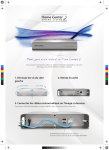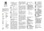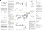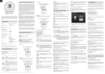
1
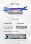
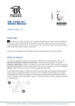
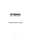
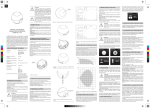
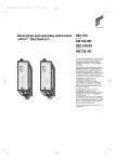
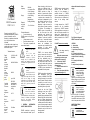
User manual
ON/OFF connector
FGS 211 v1.1
System
temperatu
re
limitation
Work
temperatu
re
For
assembly
in boxes
Radio
protocol
Range
up to approx. 50m
on the open area
up to approx. 30m
on the building
premises
(depending on
building materials)
Dimensio
ns (height
x width x
depth):
15 x 42 x 38 mm
0 - 40 °C
Ø ≥ 50mm
I
GENERAL
INFORMATION
ABOUT FIBARO SYSTEM:
Z-Wave
FIBARO constitutes a system of
house automatics based upon Z-
Technical features:
Conformit
y with the
EU norms
868 MHz
Technical information
•
Control via devices of
FIBARO system or of any Z-wave
controller.
•
Microprocessor control.
•
Executive elements: relays.
•
The device co-operates with
mono-stable, bistable.
DANGER
Danger of fatal electric
shock
All
of
the
works
connected
with
the
execution of device's
assembly may be conducted only
qualified and authorized electrician.
The national law regulations have to be
observed.
Danger
Life danger caused by the
current
Even when the device is
turned off there may be
voltage on its output. All of the works,
which aim at change of setting
configuration or of load charge should
always be executed with the voltage
turned off by previously turned on
safety device.
Hints
The ON/OFF connector
must not be connected to
the load heaver then
recommended (details in technical data)
Connect in accordance with diagram
placed in user manual. Incorrect
connection can be dangerous.
Remotely controlled ON/OFF
connector manufactured by FIBARO
system is intended for work in
electric box or anywhere where load
(up to 3kW) is needed to be
controlled.
It is possible to send a signal to any
system, which we wont to integrate
with FIBARO system.
Supply
voltage
Maximal
load
current
for single
AC input
Maximal
load
current
for single
DC input
Input
power
Radio
frequency
110-230 V ±10%
50Hz/60Hz
8A/230V 50/60Hz
8A/30V
up to 3kW
EN 55015
(interferences)
EN 60669-2-1
(exploitation
safety)
105 °C
Wave technology, which does not
require any additional wiring. In
comparison with other systems,
FIBARO provides a range of
benefits. In general radio systems
create a direct connection between
a receiver and a transmitter. The
radio signal is dampened by all of
the obstacles found along its way
(walls, furniture, etc. in the
apartment). In the worst case, the
radio system will cease to perform
its functions. The advantage of
FIBARO system is constituted by
the fact that apart from both
transmitting and receiving the
devices also constitute a signal
“duplicator”. In the case, in which a
direct way of connection between
the transmitter and the receiver
cannot
be
established,
the
connection may be realized via the
application
of
other
devices
mediating in the transmission.
FIBARO is a two-way wireless
system. It means that not only the
signal is sent to the receivers but
that they additionally send a
confirmation of its reception. Thus,
they confirm their state so that we
may verify whether the device has
actually been turned on. The safety
of FIBRO system transmission is
comparable with wire systems.
FIBARO works within a free band for
data
transmission
upon
the
frequency of 868MHz. Each FIBRO
network possesses its own unique
home ID number. Therefore, there is
a possibility to co-exist for two or
more independent systems within
one building without any conflict.
Despite the fact that Z-Wave
technology is new, just as Wi-Fi it
officially became an obligatory
standard. Many manufacturers from
different fields offer solutions based
upon the Z-Wave technology and
they are mutually compatible. Such
a situation results in the fact that the
system is future-prospective and will
allow for further development. More
information may be found on the
following website:
www.fibaro.com.
FIBARO creates a dynamic network
structure. From the moment of
turning off, the placement of
particular devices of FIBARO
system is automatically updated in
the actual time via confirmation of
states in the working “mesh”
network.
A single universal box ON/OFF
connector
will
be
hereinafter
referred to as ON/OFF connector.
With its application one may turn on
and turn off device connected to its
clamps (see: Technical data) via
radio waves, controllers and a key
directly connected to the ON/OFF
connector.
II ON/OFF connector’s assembly
Life danger caused by
the current
1.
Before the commencement
of assembly procedure ensure
that the power is turned off.
2.
Connect the ON/OFF
connector according to the
diagram below.
3.
Place the whole device in
the electric box.
4.
Place the antenna (the hints
are located below figure 1).
single connector
option with alternative load power
supply.
Fig.1 Electrical diagram of
ON/OFF connector’s connection.
LEGEND:
L – phase clamp
N – neutral clamp
I – input clamp of load power
supply
S1 – a clamp for the button
number 1 (possesses an option to
set the device to the learning
mode)
S2 – a clamp for the button
number 2
O – output clamp for the load
CAUTION
there is possibility of
supply with voltage
different then supply
voltage of ON/OFF
connector (it can be different phase,
different voltage or even DC power
supply. See Technical features for
more details.
Endurance on device
depends on power
load. For resistance
power load (light bulb
etc.) 8A is 200 000
connection cycles. If it is inductive
load e.g. glow tube with cosφ=0.6 it
is needed to restrict current to 6A in
order to keep same device life time.
HINTS FOR ANTENNA
SETTLEMENT:
Conduct the antenna at
a possibly long
distance from metal
elements (connectors, ring brackets,
etc.), in order to prevent interruption
of the radio signal.
Metal surfaces located
within the nearest
surroundings (e.g.
metal boxes mounted
under plaster, metal
frame slats) may influence the
reception capacity, thus worsening
the range of the device work!
Do not cut or shorten
the antenna. Its length
is perfectly adjusted to
the band, within within
which the system
works.
Caution
It has to be
emphasized that the
key connected to the
S1 activates the
device's learning mode
(Include/Exclude)
Dictionary
•
Inclusion – the device sends
Node Info frame, which enables
to add it to Z-Wave network.
•
Exclusion – the removal of the
device from Z-Wave network.
•
Association – control of other
Z-Wave network devices
•
MultichannelAssociation –
control of other multichannel
devices within Z-Wave network.
III ON/OFF connector's activation
1. ON/OFF connector’s
installation procedure
STEP 1 Connect the device
according to the electric diagram
shown on figure 1. Turn off the
power supply 230V. [Addition or
removal of] the ON/OFF
connector[to \ or from] z-wave
network [Inclusion/ Exclusion]
STEP 2 The ON/OFF connector
must be located within the range of
Home Center controller, because
the mode of adding to Fibaro system
requires the direct communication
with the controller. (distance up to
40m)
STEP 3 Identify key number 1. If
the device is connected as at figure
1 it will be key, which closes circuit
number 1.
STEP 4 Set Home Center
controller on the mode of adding or
removing of the device to/from the
network (see: the instruction of
Home Center controller)
STEP 5 The ON/OFF connector
enters the mode of adding and
removing after a quick triple clicking
of the key number 1. If it is bistable
switch, change its state three times.
Caution I: The
ON/OFF connector
cancels the learning
mode after a single
pushing of the key
number 1. Thus, the quadruple
pushing of the key number 1 will
not add the device to the network
Caution II: The
ON/OFF connector is
adjusted to work with
monostable switches
(that is unipolar
switch or bell switch) by default.
In the case of adding to the
network the ON/OFF connector
with bistable switch verify
whether all of the switch's
contacts are open (turned off),
because the switch's short-circuit
means turning off of the key,
which will disable the correct
process of adding of the ON/OFF
connector into FIBARO system.
During installation time it is
recommended to use monostable keys!
STEP 6 The correct process of
adding of the device to the network
will be signalled on the controller
(see: Home Center controller’s
instruction).
2. ON/OFF connector’s reset procedure
The ON/OFF connector has got two
procedures, which enable to reset
the device.
Method I Via the procedure of
removing (“exclusion”) of the
ON/OFF connector from the existing
Z-Wave network. It is conducted
with the application of a controller,
which possesses the function of
adding and removing
(inclusion/exclusion) of devices from
Z-Wave network (see: Home Center
controller’s instruction). Such a
controller does not have to be a part
of the network, which hosts the
removed device.
Method IITo reset ON/OFF
connector settings: connect power
and until 5 seconds click button S1
and hold button S2
3. Control of the ON/OFF
connector via switches.
Mono-stable switch (after the key
release the spring automatically
bounces, causing disconnection)
Turning the circuit on/off: shortly
push key number 1 (refer to fiig.1)
Bistable switch (acts as a switch does not going back after the key
release)
Turning the circuit on/off, the change
of position of the key on opposed.
4. Control of the ON/OFF
connector via ALL ON / ALL OFF
command
The ON/OFF connector executes
ALL ON / ALL OFF commands,
which may be sent via Home Center
or other controller, which belongs to
the system. Usually ALL ON / ALL
OFF commands are implemented
within remote controls, which use zwave protocol and are applied for
issuing of commands directed to the
whole system.
Both ALL ON and ALL OFF
commands are accepted by the
ON/OFF connector by default. The
implementation of changes may be
executed by means of saving the
correct value into the configuration
register
number 1.
5. ON/OFF connector's controller
via main controller of Fibaro
system (Home Center)
After the conduction of procedure of
adding of ON/OFF connector into
the network, it will be represented
within the Fibaro system controller
by means of the following icon:
associated device may be very long.
In order to add an association (with
the application of Home Center
controller) one has to move to the
device options,
clicking on the
following icon:
Choose device options. Then
determine the group and the type of
device to be associated. The
process of sending by the controller
of the proper information to the
devices included in the associated
groups may take even several
minutes.
Fig. 2 ON/OFF connector's icon
within Home Center controller.
Turn on/turn off devices connected
to ON/OFF connector can be done
by clicking appropriate icon
ON/OFF.
IV Association
The application of association allows
ON/OFF connector to directly
control the other device within zwave network, e.g. other dimmer,
transmitting connector, roller shutter.
CAUTION. Association
allows for sending of
direct control
commands between
the devices and the
main controller, but it does not
participate into the process of
communication.
The ON/OFF connector allows for
association of two groups.
1.The group is ascribed to the key
number 1
2.The group is ascribed to the key
number 2
The ON/OFF connector enables the
control of 16 ordinary devices and 7
MultiChannel ones, 1 field out of
which is reserved for the network
controller. It is recommended not to
use more than 10 devices because
the time required by the device to
issue a command to each of the
CAUTION If during the
time, in which the
device sends control
commands, the key is
pushed anew, the
process of sending of present
commands will be interrupted and
the process of sending of new
commands will occur.
ON/OFF connector FGS211
supports multichannel devices.
Multichannel devices have in one
physical device two or more
independent circuits.
V The second endpoint
virtual
The second endpoint has no
physical connection to the relay is
virtual drvice. The second endpoint
is used to activate scen. If FGS211
is connected to the Home Centre
Fibaro default, the second endpoint
is hidden. HC allows detection of
two events.
1)
the second endpoint is off.
2)
the second endpoint is on.
There is a possibility to assign
scenes for these two events.
Local button 2 changes status for
virtual endpoint 2
VI Configuration
0 – mono-stable switch
In Fibaro interface following settings
are available in simple options,
which we choose by checking
appropriate fields.
1 – bistable switch
In order to move to the ON/OFF
connector's configuration (with the
application of Fibaro controller)
move to the device option, clicking
on the following icon:
Choose device option.
Parameter number 16 – Saving of
the device state after the power
supply black-out. The ON/OFF
connector will return to the last
state before the power supply
black-out. default value 1
The possibility of parameter change
0,1:
0 – the ON/OFF connector does not
save the state after the power
supply black-out; it returns to the
turn off state
Parameter number 1 –
Activation/deactivation of ALL
ON/ALL OFF functions default
value 255
1 – the ON/OFF connector saves
the state before the power supply
black-out
Possible configuration parameters:
Possible configuration parameters
for following parameters (30-33):
255
Default
ALL ON active
ALL OFF active.
0
ALL ON non active
ALL OFF non
1-ALARM RELAY DISABLE –
device turns off after alarm
detection.
1
ALL ON non active
ALL OFF active
2-ALARM RELAY ENABLE - device
turns on after alarm detection.
2
ALL ON active
ALL OFF non
3-ALARM FLASHING – device
periodically changes state on
opposite after alarm detection,
during 10 minutes.
active
active
Parameter number 13 – Allows
change of state (turn on/turn off)
for bistable switches (see
parameter 14) , default value 0
0-DACTIVATION – device don't
react to alarm frames
Parameter number 30 – General
alarm set on relay 1. default value
3
The possibility of parameter change
0-1:
ALARM FLASHING
0 – ON/OFF sets on change of key
state
Parameter number 31 – Flood
alarm, set on relay 1. default value
2
1 – ON is active when contacts are
closed OFF is active when contacts
are open
Parameter number 14 – The type
of switch may be chosen from
mono-stable or bistable switches,
default value 1
The possibility of parameter change
0,1:
ALARM RELAY ENABLE
Parameter number 32 – Smoke,
CO, CO2 alarm set on relay 1.
default value 3
ALARM FLASHING
Parameter number 39 – Time of
active alarm. Default value 600.
VII Advanced function
Alarm frames handling
Fibaro systems allows to set
reaction of devices on alarm
situations (reaction on
ALRM_REPORT and
SENSOR_ALARM _REPORT
frames). FIBARO ON/OFF
connector handles following types of
alarms:
•
0x00 [hex]GENERAL_ALARM
•
0x03 [hex] ALARM CO2, 0x02
[hex] ALARM CO, 0x01 [hex]
ALARM SMOKE
•
0x05 [hex] ALARM WATER
•
0x04 [hex] ALARM HEAT
Alarm frames are sent by sensor
devices of the system (e.g. flood
detectors, smoke detectors, motion
detectors, etc.)
Device can react on received frames
in following ways (configuration can
be done in configuration
parameters, see V Configuration):
•
0-DEACTIVATION – device
don't react on alarm frames
•
1-ALARM ON- device turns
on after alarm detection
•
2-ALARM OFF- device turns
off after alarm detection
•
3-ALARM FLASHING- device
periodically changes state on
opposite after alarm detection (turns
on, turns off alternately). ON/OFF
connector has two independent
alarm groups (every relay can
individual react on alarm frames).
Fibaro system
allows to handle
only Alarm
Version 1 Reports
VIII ON/OFF connector’s
operation
The ON/OFF connector may be
operated via the following
operational elements:
- any controller compatible with the
system (e.g. Home Center
controller)
- mobile phone (e.g. IPhone as well
as mobile phones of other
manufacturers equipped with
appropriate control application)
- devices of tablet type (e.g. IPod)
- via PC, with the use of internet
browser
- via the key connected to the
ON/OFF connector
IX Procedures conducted
in the case of interruptions
The device does not react to the
programmed transmitter:
• Ensure that the maximal range
was not exceeded and that on the
signal way there are no obstacles,
such as metal surfaces, e.g. metal
wardrobes, reinforced ceilings and
bearing walls, etc.
• Ensure if the device is not set to
program mode.
• Repeat the process of
programming one more time.
X TERMS AND
CONDITIONS OF THE
GUARANTEE
1.
The Guarantor of the
Device quality is FIBAR GROUP Sp.
z o.o. (hereinafter referred to as
„Manufacturer”)
domiciled
at
Poznań, 6A Człopska Street; 60-453
Poznań, entered into the National
Court Registry by the Regional Court
in
Poznań,
8th
Economical
Department of the National Court
Registry, under the KRS number of:
370151, NIP 7811858097, REGON:
301595664, with company equity of
5000 PLN.
2.
The Manufacturer shall
bear the responsibility for the
improper work of the Device, which
stems from the physical defects
(material or production defects)
found in the Device within the period
of 12 months from the day of its
sale.
3.
The Guarantee is in force
and is applied only on the territory of
the Republic of Poland.
4.
During the period of
Guarantee validity, the Guarantor
shall be obliged to remove the
revealed defects free of charge by
means of repair or replacement (at
the Guarantor’s sole discretion) of
all of the defective Device’s
elements for new or regenerated
and undamaged elements. In the
case of the lack of possibility to
perform repair works, the Guarantor
reserves the right to replace the
Device for a new or generated and
undamaged one, whose physical
state shall not be worse that the
state of the Device owned by the
Client.
5.
Should in special cases
(e.g. the lack of Device within the
commercial offer) the replacement of
the Device for the one of the same
type be impossible, the Guarantor
may replace the Device for another
one, with possibly most similar
technical parameters. Such an
action shall be considered as the
execution of the Guarantor’s duties.
The Guarantor shall not refund
money spent on the purchased
Device.
6.
The owner of the valid
Guarantee document reports the
claims with regard to the Guarantee
via guarantee service. One should
remember that before the report of
guarantee claim it is useful to
contact our company via telephone
or via the internet technical
assistance. In more than a half
cases, the Client’s problems are
solved remotely, the fact, which
allows to avoid the loss of time and
costs
with
regard
to
the
unnecessarily activated Guarantee
procedure. Should the remote
solution of the problem be
impossible, the Client will be asked
to fill in the application form in order
to obtain authorization via internet
website
www.fibargroup.com
In the
case of reporting of a correct claim
You will receive the confirmation of
its reception as well as a unique
report number (RMA).
7.
There is also a possibility
to report the claim via telephone call.
In such a case the call will be
recorded, the fact about which the
Client will be informed by the
consultant before the acceptance of
claim report. Immediately after the
report reception consultant will
inform the Client about the report
number (the so-called RMA).
8.
In the case of reporting of
a correct claim the representative of
the Authorized Guarantee Service
(hereinafter referred to as “AGS”)
will contact the Client and determine
the day and the place of the visit of
technicians, who will check the
correctness of Device’s functioning
in presence of Client.
9.
The
defects
revealed
during the period of Guarantee
validity shall be removed within 30
days at latest, counting from the
date of delivery of the Device to
AGS. The period of Guarantee
validity shall be extended with time,
in which the Device is kept by AGS.
10.
The claimed Device shall
be rendered accessible by the Client
with
the
complete
standard
equipment
and
documents
confirming its purchase.
11.
The elements replaced
with regard to the Guarantee
constitute the ownership of the
Manufacturer. All of the elements
enumerated within claim process
are
encompassed
with
the
Guarantee valid until the period of
validity of the Device’s basic
Guarantee. The period of Guarantee
validity for a replaced element is not
subject to extension.
12.
The cost of travel to the
claimed Device or of its delivery to
the service shall be borne by the
Guarantor. In the case of an
unjustified summoning of the
service, the Service has a right to
impose on the Client the costs of
travel and manipulative costs
connected to the explanation of the
matter.
13.
AGS rejects to accept the
claim only in the following cases:
-in the case, in which the Device is
exploited against its intended use
and the user’s manual,
-in the case, in which the Client
renders accessible the Device,
which is incomplete, has no fittings
or data plate,
-in the case, in which the defect is
different than material or productive
one found in the Device,
-in the case of the invalid Guarantee
document and the lack of purchase
receipt,
14.
The Guarantor shall not
be responsible for the defects in
property caused by the defective
Device. The Guarantor shall not be
responsible for indirect, collateral,
special, consequential, or moral
losses, nor for damages, including
lost
benefits,
savings,
data,
advantages, third party’s claims as
well as any other property or
personal defects resulting from or
connected to the exploitation of the
Device.
15.
The quality Guarantee
does not encompass the following
issues:
mechanical defects (cracks, breaks,
cuts, wears, physical misshapes
caused by a blow, fall or dropping on
the Device of another object or
caused by the exploitation against
the
Device’s
intended
use
determined
within
the
user’s
manual);
the defects caused by the external
reasons,
such
as:
flood,
thunderstorm, fire, lightning stroke,
calamities,
earthquakes,
wars,
social unrests, force majeure,
unforeseen accidents, robbery, liquid
flooding, bacteria leakage, weather
conditions,
the
influence
of
sunbeams, sand, humidity, high or
low temperature, air contamination;
the defects caused
by the
improperly working software, as a
result of virus attack or caused by
the lack of conduction of software
updating procedure according to the
Manufacturer’s recommendations;
the defects caused by: overvoltage
within the power supply and/or
telecommunication network or by
the execution of the Device’s
connection
via
a
method
incompatible with the user’s manual
or by connection of other products,
whose
connection
is
not
recommended by the Manufacturer;
caused by the work or storage of the
Device
in
the
extremely
unfavourable conditions, that is in
the presence of high humidity,
dustiness, too low (frost) or too high
temperature. The detailed terms and
conditions, in which the Device may
be exploited are determined within
the user’s manual;
the defects caused as a result of
exploitation of accessories not
recommended by the Manufacturer;
caused by the defective electrical
installation conducted by the user,
including the application of incorrect
safety devices;
the defects caused by the Client’s
negligence
of
conduction
of
maintenance
and
service
procedures enumerated within the
user’s manual;
the defects caused
by the
exploitation of non-original, spare
parts
and
equipment
parts
inappropriate for a given model,
execution of repair works or
changes conducted by unauthorized
persons;
the defects caused by continuity of
work with defective Device or
fittings.
16.
The
scope
of
the
Guarantee repair work does not
encompass periodical maintenance
or inspection of the Device,
especially cleaning, regulations,
verification of functioning, correction
of service errors or software
parameters or other activities, which
should be conducted by the user
(the Purchaser). The Guarantee
does not encompass the natural
wear of the Device’s elements as
well as of other parts, which
possess determined period of
functioning and are enumerated
within the user’s manual and
technical documentation.
17.
Should
the
type
of
product’s
defect
be
not
encompassed within the Guarantee,
the Manufacturer reserves the right
to remove such a defect at his own
discretion, conducting the repair of
the defective or damaged part or
rendering
the
sub-assemblies
accessible for the conduction of the
necessary
repair
works
or
replacement.
18.
The Guarantee for the
purchased goods does not exclude,
limit, nor suspends the Purchaser’s
rights stemming from the product’s
incompatibility with the agreement.
The device may be
used with all of the
devices, which
possess Z-Wave
certificate; It should
also co-operate with the devices
manufactured by different
manufacturers.
Every device, which is compatible
with Z-Wave may be included in
Fibaro system.
FIBARGROUP
FIBARO
In the case of technical questions
please contact the client service
centre in Your company.
www.fibargroup.com