1
Mellanox WinOF-2 User Manual
Rev 1.21
SW version 1.21.51000
www.mellanox.com
Rev 1.21
NOTE:
THIS HARDWARE, SOFTWARE OR TEST SUITE PRODUCT (“PRODUCT(S)”) AND ITS RELATED
DOCUMENTATION ARE PROVIDED BY MELLANOX TECHNOLOGIES “AS-IS” WITH ALL FAULTS OF ANY
KIND AND SOLELY FOR THE PURPOSE OF AIDING THE CUSTOMER IN TESTING APPLICATIONS THAT USE
THE PRODUCTS IN DESIGNATED SOLUTIONS. THE CUSTOMER'S MANUFACTURING TEST ENVIRONMENT
HAS NOT MET THE STANDARDS SET BY MELLANOX TECHNOLOGIES TO FULLY QUALIFY THE PRODUCT(S)
AND/OR THE SYSTEM USING IT. THEREFORE, MELLANOX TECHNOLOGIES CANNOT AND DOES NOT
GUARANTEE OR WARRANT THAT THE PRODUCTS WILL OPERATE WITH THE HIGHEST QUALITY. ANY
EXPRESS OR IMPLIED WARRANTIES, INCLUDING, BUT NOT LIMITED TO, THE IMPLIED WARRANTIES OF
MERCHANTABILITY, FITNESS FOR A PARTICULAR PURPOSE AND NONINFRINGEMENT ARE DISCLAIMED.
IN NO EVENT SHALL MELLANOX BE LIABLE TO CUSTOMER OR ANY THIRD PARTIES FOR ANY DIRECT,
INDIRECT, SPECIAL, EXEMPLARY, OR CONSEQUENTIAL DAMAGES OF ANY KIND (INCLUDING, BUT NOT
LIMITED TO, PAYMENT FOR PROCUREMENT OF SUBSTITUTE GOODS OR SERVICES; LOSS OF USE, DATA,
OR PROFITS; OR BUSINESS INTERRUPTION) HOWEVER CAUSED AND ON ANY THEORY OF LIABILITY,
WHETHER IN CONTRACT, STRICT LIABILITY, OR TORT (INCLUDING NEGLIGENCE OR OTHERWISE)
ARISING IN ANY WAY FROM THE USE OF THE PRODUCT(S) AND RELATED DOCUMENTATION EVEN IF
ADVISED OF THE POSSIBILITY OF SUCH DAMAGE.
Mellanox Technologies
350 Oakmead Parkway Suite 100
Sunnyvale, CA 94085
U.S.A.
www.mellanox.com
Tel: (408) 970-3400
Fax: (408) 970-3403
© Copyright 2015. Mellanox Technologies. All Rights Reserved.
Mellanox®, Mellanox logo, BridgeX®, CloudX logo, Connect-IB®, ConnectX®, CoolBox®, CORE-Direct®, GPUDirect®,
InfiniHost®, InfiniScale®, Kotura®, Kotura logo, Mellanox Federal Systems®, Mellanox Open Ethernet®, Mellanox
ScalableHPC®, Mellanox Connect Accelerate Outperform logo, Mellanox Virtual Modular Switch®, MetroDX®, MetroX®,
MLNX-OS®, Open Ethernet logo, PhyX®, SwitchX®, TestX®, The Generation of Open Ethernet logo, UFM®, Virtual
Protocol Interconnect®, Voltaire® and Voltaire logo are registered trademarks of Mellanox Technologies, Ltd.
Accelio™, CyPU™, FPGADirect™, HPC-X™, InfiniBridge™, LinkX™, Mellanox Care™, Mellanox CloudX™, Mellanox
Multi-Host™, Mellanox NEO™, Mellanox PeerDirect™, Mellanox Socket Direct™, Mellanox Spectrum™, NVMeDirect™,
StPU™, Spectrum logo, Switch-IB™, Unbreakable-Link™ are trademarks of Mellanox Technologies, Ltd.
All other trademarks are property of their respective owners.
2
Mellanox Technologies
Document Number: MLNX-15-3280
Rev 1.21
Table of Contents
Document Revision History . . . . . . . . . . . . . . . . . . . . . . . . . . . . . . . . . . . . . . . . . . . . . . . . . 6
About this Manual . . . . . . . . . . . . . . . . . . . . . . . . . . . . . . . . . . . . . . . . . . . . . . . . . . . . . . . . . 7
Scope . . . . . . . . . . . . . . . . . . . . . . . . . . . . . . . . . . . . . . . . . . . . . . . . . . . . . . . . . . . . . . . . 7
Intended Audience . . . . . . . . . . . . . . . . . . . . . . . . . . . . . . . . . . . . . . . . . . . . . . . . . . . . . . 7
Documentation Conventions . . . . . . . . . . . . . . . . . . . . . . . . . . . . . . . . . . . . . . . . . . . . . . 7
Common Abbreviations and Acronyms . . . . . . . . . . . . . . . . . . . . . . . . . . . . . . . . . . . . . . 8
Related Documents . . . . . . . . . . . . . . . . . . . . . . . . . . . . . . . . . . . . . . . . . . . . . . . . . . . . . 9
Chapter 1 Introduction . . . . . . . . . . . . . . . . . . . . . . . . . . . . . . . . . . . . . . . . . . . . . . . . . . . 10
1.1
1.2
1.3
Supplied Packages . . . . . . . . . . . . . . . . . . . . . . . . . . . . . . . . . . . . . . . . . . . . . . . . 10
WinOF-2 Set of Documentation . . . . . . . . . . . . . . . . . . . . . . . . . . . . . . . . . . . . . 10
Windows MPI (MS-MPI) . . . . . . . . . . . . . . . . . . . . . . . . . . . . . . . . . . . . . . . . . . 11
Chapter 2 Installation . . . . . . . . . . . . . . . . . . . . . . . . . . . . . . . . . . . . . . . . . . . . . . . . . . . . 12
2.1
2.2
2.3
Hardware and Software Requirements . . . . . . . . . . . . . . . . . . . . . . . . . . . . . . . . 12
Downloading Mellanox WinOF-2 Driver . . . . . . . . . . . . . . . . . . . . . . . . . . . . . . 12
Installing Mellanox WinOF-2 Driver . . . . . . . . . . . . . . . . . . . . . . . . . . . . . . . . . 13
2.3.1 Attended Installation . . . . . . . . . . . . . . . . . . . . . . . . . . . . . . . . . . . . . . . . . . . . . . . 13
2.3.2 Unattended Installation . . . . . . . . . . . . . . . . . . . . . . . . . . . . . . . . . . . . . . . . . . . . . 18
2.4
2.5
2.6
Installation Results. . . . . . . . . . . . . . . . . . . . . . . . . . . . . . . . . . . . . . . . . . . . . . . . 19
Extracting Files Without Running Installation . . . . . . . . . . . . . . . . . . . . . . . . . . 19
Uninstalling Mellanox WinOF-2 Driver . . . . . . . . . . . . . . . . . . . . . . . . . . . . . . . 21
2.6.1 Attended Uninstallation . . . . . . . . . . . . . . . . . . . . . . . . . . . . . . . . . . . . . . . . . . . . 21
2.6.2 Unattended Uninstallation. . . . . . . . . . . . . . . . . . . . . . . . . . . . . . . . . . . . . . . . . . . 22
2.7
Firmware Upgrade . . . . . . . . . . . . . . . . . . . . . . . . . . . . . . . . . . . . . . . . . . . . . . . . 22
Chapter 3 Features Overview and Configuration . . . . . . . . . . . . . . . . . . . . . . . . . . . . . 23
3.1
Ethernet Network. . . . . . . . . . . . . . . . . . . . . . . . . . . . . . . . . . . . . . . . . . . . . . . . . 23
3.1.1
3.1.2
3.1.3
3.1.4
3.1.5
3.1.6
3.1.7
3.2
Mode Configuration . . . . . . . . . . . . . . . . . . . . . . . . . . . . . . . . . . . . . . . . . . . . . . .
Assigning Port IP After Installation . . . . . . . . . . . . . . . . . . . . . . . . . . . . . . . . . . .
RDMA over Converged Ethernet (RoCE) . . . . . . . . . . . . . . . . . . . . . . . . . . . . . .
Teaming and VLAN . . . . . . . . . . . . . . . . . . . . . . . . . . . . . . . . . . . . . . . . . . . . . . .
Configuring Quality of Service (QoS) . . . . . . . . . . . . . . . . . . . . . . . . . . . . . . . . .
Configuring the Ethernet Driver . . . . . . . . . . . . . . . . . . . . . . . . . . . . . . . . . . . . . .
Receive Side Scaling (RSS) . . . . . . . . . . . . . . . . . . . . . . . . . . . . . . . . . . . . . . . . .
23
23
25
30
32
35
35
Storage Protocols . . . . . . . . . . . . . . . . . . . . . . . . . . . . . . . . . . . . . . . . . . . . . . . . . 36
3.2.1 Deploying SMB Direct . . . . . . . . . . . . . . . . . . . . . . . . . . . . . . . . . . . . . . . . . . . . . 36
3.3
Virtualization . . . . . . . . . . . . . . . . . . . . . . . . . . . . . . . . . . . . . . . . . . . . . . . . . . . . 38
3.3.1 Hyper-V with VMQ . . . . . . . . . . . . . . . . . . . . . . . . . . . . . . . . . . . . . . . . . . . . . . . 38
3.3.2 Network Virtualization using Generic Routing Encapsulation (NVGRE) . . . . . . 38
3.3.3 Single Root I/O Virtualization (SR-IOV) . . . . . . . . . . . . . . . . . . . . . . . . . . . . . . . 42
3.4
Configuration Using Registry Keys. . . . . . . . . . . . . . . . . . . . . . . . . . . . . . . . . . . 56
3.4.1 Finding the Index Value of the Network Interface . . . . . . . . . . . . . . . . . . . . . . . . 56
Mellanox Technologies
3
Rev 1.21
3.4.2
3.4.3
3.4.4
3.4.5
3.4.6
3.5
Basic Registry Keys . . . . . . . . . . . . . . . . . . . . . . . . . . . . . . . . . . . . . . . . . . . . . . .
Off-load Registry Keys . . . . . . . . . . . . . . . . . . . . . . . . . . . . . . . . . . . . . . . . . . . . .
Performance Registry Keys. . . . . . . . . . . . . . . . . . . . . . . . . . . . . . . . . . . . . . . . . .
Ethernet Registry Keys . . . . . . . . . . . . . . . . . . . . . . . . . . . . . . . . . . . . . . . . . . . . .
Network Direct Interface. . . . . . . . . . . . . . . . . . . . . . . . . . . . . . . . . . . . . . . . . . . .
58
60
62
65
67
Performance Tuning and Counters . . . . . . . . . . . . . . . . . . . . . . . . . . . . . . . . . . . 68
3.5.1
3.5.2
3.5.3
3.5.4
General Performance Optimization and Tuning . . . . . . . . . . . . . . . . . . . . . . . . . .
Application Specific Optimization and Tuning . . . . . . . . . . . . . . . . . . . . . . . . . .
Tunable Performance Parameters . . . . . . . . . . . . . . . . . . . . . . . . . . . . . . . . . . . . .
Adapter Proprietary Performance Counters . . . . . . . . . . . . . . . . . . . . . . . . . . . . .
68
69
69
71
Chapter 4 Utilities . . . . . . . . . . . . . . . . . . . . . . . . . . . . . . . . . . . . . . . . . . . . . . . . . . . . . . . 73
4.1
4.2
4.3
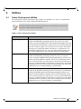
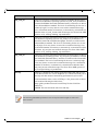
Fabric Performance Utilities . . . . . . . . . . . . . . . . . . . . . . . . . . . . . . . . . . . . . . . . 73
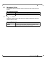
Management Utilities. . . . . . . . . . . . . . . . . . . . . . . . . . . . . . . . . . . . . . . . . . . . . . 75
Diagnostic Utilities . . . . . . . . . . . . . . . . . . . . . . . . . . . . . . . . . . . . . . . . . . . . . . . 75
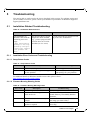
Chapter 5 Troubleshooting . . . . . . . . . . . . . . . . . . . . . . . . . . . . . . . . . . . . . . . . . . . . . . . . 76
5.1
Installation Related Troubleshooting. . . . . . . . . . . . . . . . . . . . . . . . . . . . . . . . . . 76
5.1.1 Installation Error Codes and Troubleshooting . . . . . . . . . . . . . . . . . . . . . . . . . . . 76
5.2
5.3
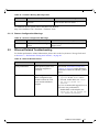
Ethernet Related Troubleshooting . . . . . . . . . . . . . . . . . . . . . . . . . . . . . . . . . . . . 77
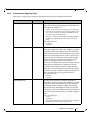
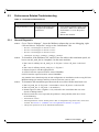
Performance Related Troubleshooting . . . . . . . . . . . . . . . . . . . . . . . . . . . . . . . . 79
5.3.1 General Diagnostic . . . . . . . . . . . . . . . . . . . . . . . . . . . . . . . . . . . . . . . . . . . . . . . . 79
5.4
5.5
5.6
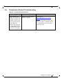
Virtualization Related Troubleshooting . . . . . . . . . . . . . . . . . . . . . . . . . . . . . . . 80
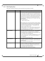
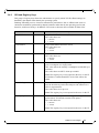
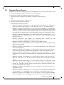
Reported Driver Events . . . . . . . . . . . . . . . . . . . . . . . . . . . . . . . . . . . . . . . . . . . . 81
State Dumping . . . . . . . . . . . . . . . . . . . . . . . . . . . . . . . . . . . . . . . . . . . . . . . . . . . 84
Appendix A NVGRE Configuration Scripts Examples . . . . . . . . . . . . . . . . . . . .86
A.1
A.2
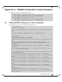
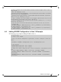
Adding NVGRE Configuration to Host 14 Example . . . . . . . . . . . . . . . . . . . 86
Adding NVGRE Configuration to Host 15 Example . . . . . . . . . . . . . . . . . . . 87
Appendix B Windows MPI (MS-MPI) . . . . . . . . . . . . . . . . . . . . . . . . . . . . . . . . . .89
B.1
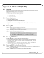
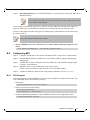
Overview . . . . . . . . . . . . . . . . . . . . . . . . . . . . . . . . . . . . . . . . . . . . . . . . . . . . 89
B.1.1 System Requirements . . . . . . . . . . . . . . . . . . . . . . . . . . . . . . . . . . . . . . . . . . . 89
B.2
B.3
B.4
B.5
Running MPI . . . . . . . . . . . . . . . . . . . . . . . . . . . . . . . . . . . . . . . . . . . . . . . . .
Directing MSMPI Traffic . . . . . . . . . . . . . . . . . . . . . . . . . . . . . . . . . . . . . . . .
Running MSMPI on the Desired Priority . . . . . . . . . . . . . . . . . . . . . . . . . . . .
Configuring MPI . . . . . . . . . . . . . . . . . . . . . . . . . . . . . . . . . . . . . . . . . . . . . .
89
89
89
90
B.5.1 PFC Example. . . . . . . . . . . . . . . . . . . . . . . . . . . . . . . . . . . . . . . . . . . . . . . . . . 90
B.5.2 Running MPI Command Examples. . . . . . . . . . . . . . . . . . . . . . . . . . . . . . . . . 91
Mellanox Technologies
4
Rev 1.21
List of Tables
Table 1:
Document Revision History . . . . . . . . . . . . . . . . . . . . . . . . . . . . . . . . . . . . . . . . . . . . . . . . 6
Table 2:
Documentation Conventions . . . . . . . . . . . . . . . . . . . . . . . . . . . . . . . . . . . . . . . . . . . . . . . 7
Table 3:
Abbreviations and Acronyms . . . . . . . . . . . . . . . . . . . . . . . . . . . . . . . . . . . . . . . . . . . . . . . 8
Table 4:
Related Documents . . . . . . . . . . . . . . . . . . . . . . . . . . . . . . . . . . . . . . . . . . . . . . . . . . . . . . . 9
Table 5:
Hardware and Software Requirements . . . . . . . . . . . . . . . . . . . . . . . . . . . . . . . . . . . . . . . 12
Table 6:
Registry Key Parameters . . . . . . . . . . . . . . . . . . . . . . . . . . . . . . . . . . . . . . . . . . . . . . . . . 30
Table 7:
Registry Keys Setting . . . . . . . . . . . . . . . . . . . . . . . . . . . . . . . . . . . . . . . . . . . . . . . . . . . . 35
Table 8:
RDMA Activity . . . . . . . . . . . . . . . . . . . . . . . . . . . . . . . . . . . . . . . . . . . . . . . . . . . . . . . . 72
Table 9:
Fabric Performance Utilities . . . . . . . . . . . . . . . . . . . . . . . . . . . . . . . . . . . . . . . . . . . . . . . 73
Table 10:
Management Utilities . . . . . . . . . . . . . . . . . . . . . . . . . . . . . . . . . . . . . . . . . . . . . . . . . . . . 75
Table 11:
Diagnostic Utilities . . . . . . . . . . . . . . . . . . . . . . . . . . . . . . . . . . . . . . . . . . . . . . . . . . . . . . 75
Table 12:
Installation Related Issues . . . . . . . . . . . . . . . . . . . . . . . . . . . . . . . . . . . . . . . . . . . . . . . . 76
Table 13:
Setup Return Codes . . . . . . . . . . . . . . . . . . . . . . . . . . . . . . . . . . . . . . . . . . . . . . . . . . . . . 76
Table 14:
Firmware Burning Warning Codes . . . . . . . . . . . . . . . . . . . . . . . . . . . . . . . . . . . . . . . . . . 76
Table 15:
Restore Configuration Warnings . . . . . . . . . . . . . . . . . . . . . . . . . . . . . . . . . . . . . . . . . . . 77
Table 16:
Ethernet Related Issues . . . . . . . . . . . . . . . . . . . . . . . . . . . . . . . . . . . . . . . . . . . . . . . . . . . 77
Table 17:
Performance Related Issues . . . . . . . . . . . . . . . . . . . . . . . . . . . . . . . . . . . . . . . . . . . . . . . 79
Table 18:
Virtualization Related Issues . . . . . . . . . . . . . . . . . . . . . . . . . . . . . . . . . . . . . . . . . . . . . . 80
Table 19:
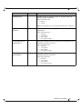
Events Causing Automatic State Dumps . . . . . . . . . . . . . . . . . . . . . . . . . . . . . . . . . . . . . 84
Mellanox Technologies
5
Rev 1.21
Document Revision History
Table 1 - Document Revision History
Document Revision
Rev 1.21
Date
Changes
November 2015
Fixed the default value of RoCE to be RoCE v1.25 instead
of RoCE v2.
September 2015
Added the following section:
• Section 3.3.3, “Single Root I/O Virtualization (SRIOV)”, on page 42
Updated the version number format - The UM version format was composed of three numbers: major, minor and subminor. The sub-minor version was removed from the UM.
Rev 1.20
September, 2015
Added the following sections:
• Section 2.2, “Downloading Mellanox WinOF-2 Driver”,
on page 12
• Section 3.3, “Virtualization”, on page 38
• Section 5.4, “Virtualization Related Troubleshooting”,
on page 80
• Appendix A,“NVGRE Configuration Scripts Examples,” on page 86
• Section 3.1.1, “Mode Configuration”
• Section 4.2, “Management Utilities”
Rev 1.10
July 8, 2015
Updated the following sections:
• Section 1, “Introduction”, on page 10
• Section 3.1.3.1, “IP Routable (RoCEv2)”, on page 26
• Section 3.1.3.6, “Configuring the RoCE Mode”, on
page 30
Rev 1.10
June 2015
Beta Release
Mellanox Technologies
6
Rev 1.21
About this Manual
Scope
Mellanox WinOF-2 is the driver for adapter cards based on the Mellanox ConnectX®-4 family of
adapter IC devices. It does not support earlier Mellanox adapter generations.
The document describes WinOF-2 Rev 1.21 features, performance, diagnostic tools, content and
configuration. Additionally, this document provides information on various performance tools
supplied with this version.
Intended Audience
This manual is intended for system administrators responsible for the installation, configuration,
management and maintenance of the software and hardware of Ethernet adapter cards. It is also
intended for application developers.
Documentation Conventions
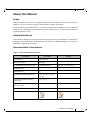
Table 2 - Documentation Conventions
Description
Convention
Example
File names
file.extension
Directory names
directory
Commands and their parameters
command param1
Required item
<>
Optional item
[ ]
Mutually exclusive parameters
{ p1, p2, p3 } or {p1 |
p2 | p3}
Optional mutually exclusive
parameters
[ p1 | p2 | p3 ]
Variables for which users supply
specific values
Italic font
enable
Emphasized words
Italic font
These are emphasized words
Note
<text>
mts3610-1 > show hosts
This is a note..
Mellanox Technologies
7
Rev 1.21
Table 2 - Documentation Conventions
Description
Convention
Warning
<text>
Example
May result in system
instability.
Common Abbreviations and Acronyms
Table 3 - Abbreviations and Acronyms (Sheet 1 of 2)
Abbreviation / Acronym
Whole Word / Description
B
(Capital) ‘B’ is used to indicate size in bytes or multiples of
bytes (e.g., 1KB = 1024 bytes, and 1MB = 1048576 bytes)
b
(Small) ‘b’ is used to indicate size in bits or multiples of bits
(e.g., 1Kb = 1024 bits)
FW
Firmware
HCA
Host Channel Adapter
HW
Hardware
IB
InfiniBand
LSB
Least significant byte
lsb
Least significant bit
MSB
Most significant byte
msb
Most significant bit
NIC
Network Interface Card
NVGRE
Network Virtualization using Generic Routing Encapsulation
SW
Software
VPI
Virtual Protocol Interconnect
IPoIB
IP over InfiniBand
PFC
Priority Flow Control
PR
Path Record
RDS
Reliable Datagram Sockets
RoCE
RDMA over Converged Ethernet
SL
Service Level
Mellanox Technologies
8
Rev 1.21
Table 3 - Abbreviations and Acronyms (Sheet 2 of 2)
Abbreviation / Acronym
Whole Word / Description
MPI
Message Passing Interface
QoS
Quality of Service
Related Documents
Table 4 - Related Documents
Document
Description
MFT User Manual
Describes the set of firmware management tools for a single InfiniBand node. MFT can be used for:
• Generating a standard or customized Mellanox firmware image
Querying for firmware information
• Burning a firmware image to a single InfiniBand nodeEnabling
changing card configuration to support SRIOV
WinOF-2 Release Notes
For possible software issues, please refer to WinOF-2 Release
Notes.
ConnectX®-4 Firmware
Release Notes
For possible firmware issues, please refer to ConnectX®-4 Firmware Release Notes.
Mellanox Technologies
9
Rev 1.21
1
Introduction
This User Manual describes installation, configuration and operation of Mellanox WinOF-2
driver Rev 1.21 package.
Mellanox WinOF-2 is composed of several software modules that contain Ethernet drivers only
(InfiniBand drivers are not supported yet). It supports 10, 25, 40, 50 or 100 Gb/s Ethernet network ports. The port speed is determined upon boot based on card capabilities and user settings.
The Mellanox WinOF-2 driver release introduces the following capabilities:
•
Support for ConnectX®-4 and ConnectX®-4 Lx single and dual port adapter cards1
•
Up to 16 Rx queues per port
•
Dedicated PCI function per physical port
•
Rx steering mode (RSS)
•
Hardware Tx/Rx checksum calculation
•
Large Send off-load (i.e., TCP Segmentation Off-load)
•
Receive Side Coalescing (RSC, or LRO in Linux)
•
Hardware multicast filtering
•
Adaptive interrupt moderation
•
Support for MSI-X interrupts
•
NDK with SMB-Direct
•
NDv1 and v2 API support in user space
•
VMQ for Hypervisor
•
Hardware VLAN filtering
•
RDMA over Converged Ethernet
• RoCE v1
• RoCE v2
1.1
•
NVGRE hardware off-load in ConnectX®-4Enhanced Transmission Selection (ETS)
•
SR-IOV Ethernet on Windows Server 2012 R2 Hypervisor with Windows Server 2012
and above guests.
•
Quality of Service (QoS)
•
Priority Flow Control (PFC)
Supplied Packages
Mellanox WinOF-2 driver Rev 1.21 includes the following package:
•
1.2
MLNX_WinOF2-1_21_All_x64.exe
WinOF-2 Set of Documentation
Under <installation_directory>\Documentation:
1. WinOF-2 does not support earlier Mellanox adapters. For earlier adapters, the Windows driver is MLNX_WinOF.
Mellanox Technologies
10
Rev 1.21
1.3
•
License file
•
User Manual (this document)
•
MLNX_WinOF-2 Release Notes
Windows MPI (MS-MPI)
Message Passing Interface (MPI) is meant to provide virtual topology, synchronization, and communication functionality between a set of processes. MPI enables running one process on several
hosts.
•
Windows MPI runs over the following protocols:
• Sockets (Ethernet)
• Network Direct (ND)
For further details on MPI, please refer to Appendix B,“Windows MPI (MS-MPI),” on page 89.
Mellanox Technologies
11
Rev 1.21
2
Installation
2.1
Hardware and Software Requirements
Table 5 - Hardware and Software Requirements
Descriptiona
Package
Windows Server 2012 R2 (64 bit only)
MLNX_WinOF2-1_21_All_x64.exe
Windows Server 2012 (64 bit only)
MLNX_WinOF2-1_21_All_x64.exe
a. The Operating System listed above must run with administrator privileges.
2.2
Downloading Mellanox WinOF-2 Driver
To download the .exe according to your Operating System, please follow the steps below:
Step 1. Obtain the machine architecture.
For Windows Server 2012 / 2012 R2
1. To go to the Start menu, position your mouse in the bottom-right corner of the
Remote Desktop of your screen.
2. Open a CMD console (Click Task Manager-->File --> Run new task, and enter
CMD).
3. Enter the following command.
> echo %PROCESSOR_ARCHITECTURE%
On an x64 (64-bit) machine, the output will be “AMD64”.
Step 2. Go to the Mellanox WinOF-2 web page at:
http://www.mellanox.com > Products > InfiniBand/VPI Drivers => Windows SW/Drivers.
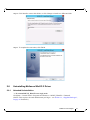
Step 3. Download the .exe image according to the architecture of your machine (see Step 1). The
name of the .exe is in the following format
MLNX_WinOF2-<version>_<arch>.exe.
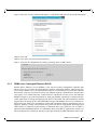
Installing the incorrect .exe file is prohibited. If you do so, an error message will be displayed. For example, if you try to install a 64-bit .exe on a 32-bit machine, the wizard
will display the following (or a similar) error message:
Mellanox Technologies
12
Rev 1.21
2.3
Installing Mellanox WinOF-2 Driver
WinOF-2 supports adapter cards based on the Mellanox ConnectX®-4 family of adapter IC
devices only. If you have ConnectX-3 and ConnectX-3 Pro on your server, you will need to install
WinOF driver.
For details on how to install WinOF driver, please refer to WinOF User Manual.
This section provides instructions for two types of installation procedures:
•
“Attended Installation”
An installation procedure that requires frequent user intervention.
•
“Unattended Installation”
An automated installation procedure that requires no user intervention.
Both Attended and Unattended installations require administrator privileges.
2.3.1
Attended Installation
The following is an example of an installation session.
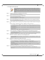
Step 1. Double click the .exe and follow the GUI instructions to install MLNX_WinOF2.
Step 2. [Optional] Manually configure your setup to contain the logs option.
> MLNX_WinOF2-1_21_All_x64.exe /v"/l*vx [LogFile]"
Step 3. [Optional] If you do not want to upgrade your firmware version1.
> MLNX_VPI_WinOF-1_21_All_win2012_x64.exe /v" MT_SKIPFWUPGRD=1"
Step 4. Click Next in the Welcome screen.
1. MT_SKIPFWUPGRD default value is False
Mellanox Technologies
13
Rev 1.21
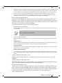
Step 5. Read then accept the license agreement and click Next.
Step 6. Select the target folder for the installation.
Mellanox Technologies
14
Rev 1.21
Step 7. The firmware upgrade screen will be displayed in the following cases:
•
If the user has an OEM card. In this case, the firmware will not be displayed.
•
If the user has a standard Mellanox card with an older firmware version, the firmware will be updated
accordingly. However, if the user has both and OEM card and a Mellanox card, only the Mellanox
card will be updated.
Step 8. Select a Complete or Custom installation, follow Step a and on, on page 16.
Mellanox Technologies
15
Rev 1.21
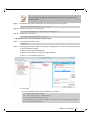
a.Select the desired feature to install:
• Performances tools - install the performance tools that are used to measure performance in user environment.
• Documentation - contains the User Manual and Release Notes
• Management tools - installation tools used for management, such as mlxstat.
b. Click Install to start the installation.
Mellanox Technologies
16
Rev 1.21
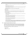
Step 9. Click Finish to complete the installation.
Mellanox Technologies
17
Rev 1.21
2.3.2
Unattended Installation
If no reboot options are specified, the installer restarts the computer whenever necessary without
displaying any prompt or warning to the user.
Use the /norestart or /forcerestart standard command-line options to control reboots.
The following is an example of an unattended installation session.
Step 1. Open a CMD console [Windows Server 2012 R2] - Click Start --> Task Manager-->File -->
Run new task --> and enter CMD.
Step 2. Install the driver. Run:
> MLNX_WinOF2-1_21_All_x64.exe /S /v"/qn"
Step 3. [Optional] Manually configure your setup to contain the logs option:
> MLNX_WinOF2-1_21_All_x64.exe /S /v"/qn" /v"/l*vx [LogFile]"
Step 4. [Optional] if you want to control whether to install ND provider or not1.
> MLNX_WinOF2_1_21_All_win2012_x64.exe /vMT_NDPROPERTY=1
Step 5. [Optional] If you do not wish to upgrade your firmware version2.
> MLNX_VPI_WinOF-1_21_All_win2012_x64.exe /v" MT_SKIPFWUPGRD=1"
Applications that hold the driver files (such as ND applications) will be closed during the unattended installation.
1. MT_NDPROPERTY default value is True
2. MT_SKIPFWUPGRD default value is False
Mellanox Technologies
18
Rev 1.21
2.4
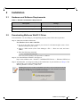
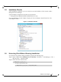
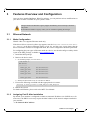
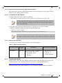
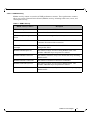
Installation Results
Upon installation completion, you can verify the successful addition of the network card(s)
through the Device Manager.
Upon installation completion, the inf files can be located at:
•
%ProgramFiles%\Mellanox\MLNX_WinOF2\Drivers\<OS>
To see the Mellanox network adapters, display the Device Manager and pull down the “Network adapters” menu.
Figure 1: Installation Results
2.5
Extracting Files Without Running Installation
To extract the files without running installation, perform the following steps.
Step 1. Open a CMD console [Windows Server 2012 R2] - Click Start --> Task Manager-->File -->
Run new task --> and enter CMD.
Step 2. Extract the driver and the tools:
> MLNX_WinOF2-1_20_All_x64 /a
•
To extract only the driver files.
> MLNX_WinOF2-1_20_All_x64 /a /vMT_DRIVERS_ONLY=1
Mellanox Technologies
19
Rev 1.21
Step 3. Click Next to create a server image.
Step 4. Click Change and specify the location in which the files are extracted to.
Mellanox Technologies
20
Rev 1.21
Step 5. Click Install to extract this folder, or click Change to install to a different folder.
Step 6. To complete the extraction, click Finish.
2.6
Uninstalling Mellanox WinOF-2 Driver
2.6.1
Attended Uninstallation
To uninstall MLNX_WinOF2 on a single node:
Click Start-> Control Panel-> Programs and Features-> MLNX_WinOF2-> Uninstall.
(NOTE: This requires elevated administrator privileges – see Section 1.1, “Supplied Packages”,
on page 10 for details.)
Mellanox Technologies
21
Rev 1.21
2.6.2
Unattended Uninstallation
If no reboot options are specified, the installer restarts the computer whenever necessary without
displaying any prompt or warning to the user.
Use the /norestart or /forcerestart standard command-line options to control reboots.
To uninstall MLNX_WinOF2 in unattended mode:
Step 1. Open a CMD console [Windows Server 2012 R2] - Click Start --> Task Manager-->File -->
Run new task --> and enter CMD.
Step 2. Uninstall the driver. Run:
> MLNX_WinOF2-1_21_All_win2012_x64.exe /S /x /v"/qn"
2.7
Firmware Upgrade
If the machine has a standard Mellanox card with an older firmware version, the firmware will be
automatically updated as part of the WinOF-2 package installation.
For information on how to upgrade firmware manually please refer to MFT User Manual:
www.mellanox.com ->Products -> InfiniBand/VPI Drivers -> Firmware Tools
Mellanox Technologies
22
Rev 1.21
3
Features Overview and Configuration
Once you have installed Mellanox WinOF-2 package, you can perform various modifications to
your driver to make it suitable for your system’s needs
Changes made to the Windows registry happen immediately, and no backup is automatically made.
Do not edit the Windows registry unless you are confident regarding the changes.
3.1
Ethernet Network
3.1.1
Mode Configuration
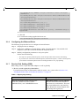
WinOF-2 Rev 1.21 supports Ethernet mode only.
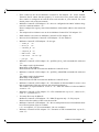
If the driver fails to start and a yellow sign appears near the "Mellanox ConnectX 10Gb Ethernet Adapter" in the Device Manager display (Code 10), and the event viewer shows that the
driver has failed to start due to unsupported mode, the correct configuration shoulf be performed.
For configuring the port types to Ethernet mode on a device, use the mlxconfig.exe utility which
is part of the MFT package, available at www.mellanox.com.
1. Install the MFT package.
2. Retrieve the device name:
a. In command prompt, run "mst status -v":
> mst status -v
MST devices:
-----------mt4099_pci_cr0
mt4099_pciconf0
mt4103_pci_cr0
mt4103_pciconf0
bus:dev.fn=04:00.0
bus:dev.fn=04:00.0
bus:dev.fn=21:00.0
bus:dev.fn=21:00.0
mt4115_pciconf0
bus:dev.fn=24:00.0
b. Identify the desired device by its "bus:dev.fn" address.
3. Execute the following command with the appropriate device name:
mlxconfig -d mt4115_pciconf0 set LINK_TYPE_P1=2 LINK_TYPE_P2=2
4. Reboot the system.
For further information, please refer to the MFT User Manual.
3.1.2
Assigning Port IP After Installation
By default, your machine is configured to obtain an automatic IP address via a DHCP server. In
some cases, the DHCP server may require the MAC address of the network adapter installed in
your machine.
To obtain the MAC address:
Mellanox Technologies
23
Rev 1.21
Step 1. Open a CMD console
[Windows Server 2012 R2] - Click Start --> Task Manager-->File --> Run new task -->
and enter CMD.
Step 2. Display the MAC address as “Physical Address”
> ipconfig /all
Configuring a static IP is the same for Ethernet adapters.
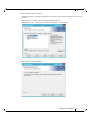
To assign a static IP address to a network port after installation:
Step 1. Open the Network Connections window. Locate Local Area Connections with Mellanox
devices.
Step 2. Right-click a Mellanox Local Area Connection and left-click Properties.
Step 3. Select Internet Protocol Version 4 (TCP/IPv4) from the scroll list and click Properties.
Mellanox Technologies
24
Rev 1.21
Step 4. Select the “Use the following IP address:” radio button and enter the desired IP information.
Step 5. Click OK.
Step 6. Close the Local Area Connection dialog.
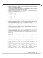
Step 7. Verify the IP configuration by running ‘ipconfig’ from a CMD console.
> ipconfig
...
Ethernet adapter Local Area Connection 4:
Connection-specific
IP Address. . . . .
Subnet Mask . . . .
Default Gateway . .
DNS
..
..
..
Suffix
....
....
....
.
.
.
.
:
: 11.4.12.63
: 255.255.0.0
:
...
3.1.3
RDMA over Converged Ethernet (RoCE)
Remote Direct Memory Access (RDMA) is the remote memory management capability that
allows server to server data movement directly between application memory without any CPU
involvement. RDMA over Converged Ethernet (RoCE) is a mechanism to provide this efficient
data transfer with very low latencies on loss-less Ethernet networks. With advances in data center
convergence over reliable Ethernet, ConnectX® EN with RoCE uses the proven and efficient
RDMA transport to provide the platform for deploying RDMA technology in mainstream data
center application at 10GigE and 40GigE link-speed. ConnectX® EN with its hardware offload
support takes advantage of this efficient RDMA transport (InfiniBand) services over Ethernet to
deliver ultra-low latency for performance-critical and transaction intensive applications such as
financial, database, storage, and content delivery networks. RoCE encapsulates IB transport and
GRH headers in Ethernet packets bearing a dedicated ether type. While the use of GRH is
optional within InfiniBand subnets, it is mandatory when using RoCE. Applications written over
IB verbs should work seamlessly, but they require provisioning of GRH information when creat-
Mellanox Technologies
25
Rev 1.21
ing address vectors. The library and driver are modified to provide mapping from GID to MAC
addresses required by the hardware.
3.1.3.1 IP Routable (RoCEv2)
RoCE has two addressing modes: MAC based GIDs, and IP address based GIDs. In RoCE IP
based, if the IP address changes while the system is running, the GID for the port will automatically be updated with the new IP address, using either IPv4 or IPv6.
RoCE IP based allows RoCE traffic between Windows and Linux systems, which use IP based
GIDs by default.
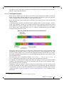
A straightforward extension of the RoCE protocol enables traffic to operate in layer 3 environments. This capability is obtained via a simple modification of the RoCE packet format. Instead
of the GRH used in RoCE, routable RoCE packets carry an IP header which allows traversal of
IP L3 Routers and a UDP header that serves as a stateless encapsulation layer for the RDMA
Transport Protocol Packets over IP.
Figure 2: RoCE and RoCE v2 Frame Format Differences
The proposed RoCEv2 packets use a well-known UDP destination port value that unequivocally
distinguishes the datagram. Similar to other protocols that use UDP encapsulation, the UDP
source port field is used to carry an opaque flow-identifier that allows network devices to implement packet forwarding optimizations (e.g. ECMP) while staying agnostic to the specifics of the
protocol header format.
The UDP source port is calculated as follows: UDP.SrcPort = (SrcPort XOR DstPort) OR
where SrcPort and DstPort are the ports used to establish the connection.
For example, in a Network Direct application, when connecting to a remote peer, the destination
IP address and the destination port must be provided as they are used in the calculation above.
The source port provision is optional.
0xC000,
Furthermore, since this change exclusively affects the packet format on the wire, and due to the
fact that with RDMA semantics packets are generated and consumed below the AP applications
can seamlessly operate over any form of RDMA service (including the routable version of RoCE
as shown in Figure 2,“RoCE and RoCE v2 Frame Format Differences”), in a completely transparent way1.
1. Standard RDMA APIs are IP based already for all existing RDMA technologies
Mellanox Technologies
26
Rev 1.21
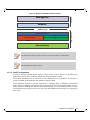
Figure 3: RoCE and RoCEv2 Protocol Stack
RDMA Application
So
ft
w
ar
e
ND/NDK API
RDMA API (Verbs)
Ty
p
ic
al
ly
H
ar
d
w
ar
e
IBTA Transport Protocol
UDP
IBTA Network Layer
IP
RoCE v2
RoCE v1
Ethernet Link Layer
The fabric must use the same protocol stack in order for nodes to communicate.
The default RoCE mode is RoCE v1.
3.1.3.2 RoCE Configuration
In order to function reliably, RoCE requires a form of flow control. While it is possible to use
global flow control, this is normally undesirable, for performance reasons.
The normal and optimal way to use RoCE is to use Priority Flow Control (PFC). To use PFC, it
must be enabled on all endpoints and switches in the flow path.
In the following section we present instructions to configure PFC on Mellanox ConnectX™
cards. There are multiple configuration steps required, all of which may be performed via PowerShell. Therefore, although we present each step individually, you may ultimately choose to write
a PowerShell script to do them all in one step. Note that administrator privileges are required for
these steps.
Mellanox Technologies
27
Rev 1.21
3.1.3.2.1 Configuring Windows Host
Since PFC is responsible for flow controlling at the granularity of traffic priority, it is
necessary to assign different priorities to different types of network traffic.
As per RoCE configuration, all ND/NDK traffic is assigned to one or more chosen priorities, where PFC is enabled on those priorities.
Configuring Windows host requires configuring QoS. To configure QoS, please follow the procedure described in Section 3.1.5, “Configuring Quality of Service (QoS)”, on page 32
3.1.3.2.1.1 Global Pause (Flow Control)
To use Global Pause (Flow Control) mode, disable QoS and Priority:
PS $ Disable-NetQosFlowControl
PS $ Disable-NetAdapterQos <interface name>
To confirm flow control is enabled in adapter parameters:
Device manager-> Network adapters-> Mellanox ConnectX-4 Ethernet Adapter-> Properties
->Advanced tab
3.1.3.3 Configuring SwitchX® Based Switch System
To enable RoCE, the SwitchX should be configured as follows:
•
Ports facing the host should be configured as access ports, and either use global pause
or Port Control Protocol (PCP) for priority flow control
•
Ports facing the network should be configured as trunk ports, and use Port Control Protocol (PCP) for priority flow control
For further information on how to configure SwitchX, please refer to SwitchX User Manual.
Mellanox Technologies
28
Rev 1.21
3.1.3.4 Configuring Arista Switch
Step 1.
Set the ports that face the hosts as trunk.
(config)# interface et10
(config-if-Et10)# switchport mode trunk
Step 2.
Set VID allowed on trunk port to match the host VID.
(config-if-Et10)# switchport trunk allowed vlan 100
Step 3.
Set the ports that face the network as trunk.
(config)# interface et20
(config-if-Et20)# switchport mode trunk
Step 4.
Assign the relevant ports to LAG.
(config)# interface et10
(config-if-Et10)# dcbx mode ieee
(config-if-Et10)# speed forced 40gfull
(config-if-Et10)# channel-group 11 mode active
Step 5.
Enable PFC on ports that face the network.
(config)# interface et20
(config-if-Et20)# load-interval 5
(config-if-Et20)# speed forced 40gfull
(config-if-Et20)# switchport trunk native vlan tag
(config-if-Et20)# switchport trunk allowed vlan 11
(config-if-Et20)# switchport mode trunk
(config-if-Et20)# dcbx mode ieee
(config-if-Et20)# priority-flow-control mode on
(config-if-Et20)# priority-flow-control priority 3 no-drop
3.1.3.4.1 Using Global Pause (Flow Control)
To enable Global Pause on ports that face the hosts, perform the following:
(config)# interface et10
(config-if-Et10)# flowcontrol receive on
(config-if-Et10)# flowcontrol send on
3.1.3.4.2 Using Priority Flow Control (PFC)
To enable Global Pause on ports that face the hosts, perform the following:
(config)# interface et10
(config-if-Et10)# dcbx mode ieee
(config-if-Et10)# priority-flow-control mode on
(config-if-Et10)# priority-flow-control priority 3 no-drop
3.1.3.5 Configuring Router (PFC only)
The router uses L3's DSCP value to mark the egress traffic of L2 PCP. The required mapping,
maps the three most significant bits of the DSCP into the PCP. This is the default behavior, and
no additional configuration is required.
Mellanox Technologies
29
Rev 1.21
3.1.3.5.1 Copying Port Control Protocol (PCP) between Subnets
The captured PCP option from the Ethernet header of the incoming packet can be used to set the
PCP bits on the outgoing Ethernet header.
3.1.3.6 Configuring the RoCE Mode
Configuring the RoCE mode requires the following:
•
RoCE mode is configured per-driver and is enforced on all the devices in the system
The supported RoCE modes depend on the firmware installed. If the firmware does not
support the needed mode, the fallback mode would be the maximum supported RoCE
mode of the installed NIC.
RoCE mode can be enabled and disabled either via the registry key or the PowerShell.
RoCE is enabled by default. To enable it using the registry key:
•
Set the roce_mode as follows:
HKEY_LOCAL_MACHINE\SYSTEM\CurrentControlSet\Services\mlx5\Parameters\Roce
For changes to take effect, please restart the network adapter after changing this registry key.
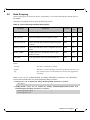
3.1.3.6.1 Registry Key Parameters
The following are per-driver and will apply to all available adapters.
Table 6 - Registry Key Parameters
3.1.4
Parameters Name
Parameter
type
roce_mode
DWORD
Description
Allowed Values and Default
Sets the RoCE mode. The following
are the possible RoCE modes:
• RoCE MAC Based
• RoCE v2
• No RoCE
•
•
•
•
RoCE MAC Based = 0
RoCE v2 = 2
No RoCE = 4
Default: No RoCE
Teaming and VLAN
Windows Server 2012 and above supports Teaming as part of the operating system. Please refer
to Microsoft guide “NIC Teaming in Windows Server 2012” following the link below:
http://www.microsoft.com/en-us/download/confirmation.aspx?id=40319
Note that the Microsoft teaming mechanism is only available on Windows Server distributions.
Mellanox Technologies
30
Rev 1.21
3.1.4.1 Configuring a Network Interface to Work with VLAN in Windows Server 2012 and Above
In this procedure you DO NOT create a VLAN, rather use an existing VLAN ID.
To configure a port to work with VLAN using the Device Manager.
Step 1.
Open the Device Manager.
Step 2.
Go to the Network adapters.
Step 3.
Go to the properties of Mellanox ConnectX®-4 Ethernet Adapter card.
Step 4.
Go to the Advanced tab.
Step 5.
Choose the VLAN ID in the Property window.
Step 6.
Set its value in the Value window.
Mellanox Technologies
31
Rev 1.21
3.1.5
Configuring Quality of Service (QoS)
3.1.5.1 QoS Configuration
Prior to configuring Quality of Service, you must install Data Center Bridging using one of the
following methods:
To Disable Flow Control Configuration
Device manager->Network adapters->Mellanox ConnectX-4 Ethernet Adapter->Properties>Advanced tab
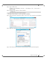
To install the Data Center Bridging using the Server Manager:
Step 1.
Open the 'Server Manager'.
Step 2.
Select 'Add Roles and Features'.
Step 3.
Click Next.
Step 4.
Select 'Features' on the left panel.
Step 5.
Check the 'Data Center Bridging' checkbox.
Step 6.
Click 'Install'.
To install the Data Center Bridging using PowerShell:
Step 1.
Enable Data Center Bridging (DCB).
PS $ Install-WindowsFeature Data-Center-Bridging
Mellanox Technologies
32
Rev 1.21
To configure QoS on the host:
The procedure below is not saved after you reboot your system. Hence, we recommend you create a script using the steps below and run it on the startup of the local
machine.
Please see the procedure below on how to add the script to the local machine startup
scripts.
Step 1.
Change the Windows PowerShell execution policy:
PS $ Set-ExecutionPolicy AllSigned
Step 2.
Remove the entire previous QoS configuration:
PS $ Remove-NetQosTrafficClass
PS $ Remove-NetQosPolicy -Confirm:$False
Step 3.
Set the DCBX Willing parameter to false as Mellanox drivers do not support this feature.
PS $ set-NetQosDcbxSetting -Willing 0
Step 4.
Create a Quality of Service (QoS) policy and tag each type of traffic with the relevant priority.
In this example, TCP/UDP use priority 1, SMB over TCP use priority 3.
PS $ New-NetQosPolicy "DEFAULT" -store Activestore -Default -PriorityValue8021Action 3
PS $ New-NetQosPolicy "TCP" -store Activestore -IPProtocolMatchCondition TCP -PriorityValue8021Action 1
PS $ New-NetQosPolicy "UDP" -store Activestore -IPProtocolMatchCondition UDP -PriorityValue8021Action 1
New-NetQosPolicy “SMB” –SMB –PriorityValue8021Action 3
Step 5.
Create a QoS policy for SMB over SMB Direct traffic on Network Direct port 445.
PS $ New-NetQosPolicy "SMBDirect" -store Activestore -NetDirectPortMatchCondition 445 PriorityValue8021Action 3
Step 6.
[Optional] If VLANs are used, mark the egress traffic with the relevant VlanID.
The NIC is referred as "Ethernet 4” in the examples below.
PS $ Set-NetAdapterAdvancedProperty -Name "Ethernet 4" -RegistryKeyword "VlanID" -RegistryValue "55"
Step 7.
[Optional] Configure the IP address for the NIC.
If DHCP is used, the IP address will be assigned automatically.
PS $ Set-NetIPInterface -InterfaceAlias “Ethernet 4” -DHCP Disabled
PS $ Remove-NetIPAddress -InterfaceAlias “Ethernet 4” -AddressFamily IPv4 -Confirm:$false
PS $ New-NetIPAddress -InterfaceAlias “Ethernet 4” -IPAddress 192.168.1.10 -PrefixLength 24 -Type Unicast
Step 8.
[Optional] Set the DNS server (assuming its IP address is 192.168.1.2).
PS $ Set-DnsClientServerAddress -InterfaceAlias “Ethernet 4” -ServerAddresses
192.168.1.2
Mellanox Technologies
33
Rev 1.21
After establishing the priorities of ND/NDK traffic, the priorities must have PFC
enabled on them.
Step 9.
Disable Priority Flow Control (PFC) for all other priorities except for 3.
PS $ Disable-NetQosFlowControl 0,1,2,4,5,6,7
Step 10. Enable QoS on the relevant interface.
PS $ Enable-NetAdapterQos -InterfaceAlias "Ethernet 4"
Step 11. Enable PFC on priority 3.
PS $ Enable-NetQosFlowControl -Priority 3
To add the script to the local machine startup scripts:
Step 1.
From the PowerShell invoke.
gpedit.msc
Step 2.
In the pop-up window, under the 'Computer Configuration' section, perform the following:
1. Select Windows Settings
2. Select Scripts (Startup/Shutdown)
3. Double click Startup to open the Startup Properties
4. Move to “PowerShell Scripts” tab
5. Click Add
The script should include only the following commands:
PS $ Remove-NetQosTrafficClass
PS $ Remove-NetQosPolicy -Confirm:$False
PS $ set-NetQosDcbxSetting -Willing 0
PS $ New-NetQosPolicy "SMB" -Policystore Activestore -NetDirectPortMatchCondition
445 -PriorityValue8021Action 3
Mellanox Technologies
34
Rev 1.21
PS $ New-NetQosPolicy "DEFAULT" -Policystore Activestore -Default -PriorityValue8021Action 3
PS $ New-NetQosPolicy "TCP" -Policystore Activestore -IPProtocolMatchCondition TCP
-PriorityValue8021Action 1
PS $ New-NetQosPolicy "UDP" -Policystore Activestore -IPProtocolMatchCondition UDP
-PriorityValue8021Action 1
PS $ Disable-NetQosFlowControl 0,1,2,4,5,6,7
PS $ Enable-NetAdapterQos -InterfaceAlias "port1"
PS $ Enable-NetAdapterQos -InterfaceAlias "port2"
PS $ Enable-NetQosFlowControl -Priority 3
PS $ New-NetQosTrafficClass -name "SMB class" -priority 3 -bandwidthPercentage 50 Algorithm ETS
6. Browse for the script's location.
7. Click OK
8. To confirm the settings applied after boot run:
PS $ get-netqospolicy -policystore activestore
3.1.6
Configuring the Ethernet Driver
The following steps describe how to configure advanced features.
Step 1.
Display the Device Manager.
Step 2.
Right-click a Mellanox network adapter (under “Network adapters” list) and left-click
Properties. Select the Advanced tab from the Properties sheet.
Step 3.
Modify configuration parameters to suit your system.
Please note the following:
3.1.7
•
For help on a specific parameter/option, check the help button at the bottom of the dialog.
•
If you select one of the entries Off-load Options, Performance Options, or Flow Control Options,
you’ll need to click the Properties button to modify parameters via a pop-up dialog.
Receive Side Scaling (RSS)
RSS settings can be set per individual adapters as well as globally.
To do so, set the registry keys listed below:
For instructions on how to find interface index in registry <nn>, please refer to Section 3.4.1,
“Finding the Index Value of the Network Interface”, on page 56.
Table 7 - Registry Keys Setting
Sub-key
HKLM\SYSTEM\CurrentControlSet\Control\Class\{4d36e972-e325-11ce-bfc108002be10318}\<nn>\*MaxRSSProcessors
Description
Maximum number of CPUs allotted.
Sets the desired maximum number of
processors for each interface. The number can be different for each interface.
Note: Restart the network adapter after
you change this registry key.
Mellanox Technologies
35
Rev 1.21
Table 7 - Registry Keys Setting
Sub-key
Description
HKLM\SYSTEM\CurrentControlSet\Control\Class\{4d36e972-e325-11ce-bfc108002be10318}\<nn>\*RssBaseProcNumber
Base CPU number. Sets the desired
base CPU number for each interface.
The number can be different for each
interface. This allows partitioning of
CPUs across network adapters.
Note: Restart the network adapter when
you change this registry key.
HKLM\SYSTEM\CurrentControlSet\Control\Class\{4d36e972-e325-11ce-bfc108002be10318}\<nn>\*NumaNodeID
NUMA node affinitization
HKLM\SYSTEM\CurrentControlSet\Control\Class\{4d36e972-e325-11ce-bfc108002be10318}\<nn>\*RssBaseProcGroup
Sets the RSS base processor group for
systems with more than 64 processors.
3.2
Storage Protocols
3.2.1
Deploying SMB Direct
The Server Message Block (SMB) protocol is a network file sharing protocol implemented in
Microsoft Windows. The set of message packets that defines a particular version of the protocol
is called a dialect.
The Microsoft SMB protocol is a client-server implementation and consists of a set of data packets, each containing a request sent by the client or a response sent by the server.
SMB protocol is used on top of the TCP/IP protocol or other network protocols. Using the SMB
protocol allows applications to access files or other resources on a remote server, to read, create,
and update them. In addition, it enables communication with any server program that is set up to
receive an SMB client request.
3.2.1.1 SMB Configuration Verification
3.2.1.1.1 Verifying Network Adapter Configuration
Use the following PowerShell cmdlets to verify Network Direct is globally enabled and that you
have NICs with the RDMA capability.
•
Run on both the SMB server and the SMB client.
PS $ Get-NetOffloadGlobalSetting | Select NetworkDirect
PS $ Get-NetAdapterRDMA
PS $ Get-NetAdapterHardwareInfo
3.2.1.1.2 Verifying SMB Configuration
Use the following PowerShell cmdlets to verify SMB Multichannel is enabled, confirm the
adapters are recognized by SMB and that their RDMA capability is properly identified.
Mellanox Technologies
36
Rev 1.21
•
On the SMB client, run the following PowerShell cmdlets:
PS $ Get-SmbClientConfiguration | Select EnableMultichannel
PS $ Get-SmbClientNetworkInterface
•
On the SMB server, run the following PowerShell cmdlets1:
PS $ Get-SmbServerConfiguration | Select EnableMultichannel
PS $ Get-SmbServerNetworkInterface
PS $ netstat.exe -xan | ? {$_ -match "445"}
3.2.1.1.3 Verifying SMB Connection
To verify the SMB connection on the SMB client:
Step 1.
Copy the large file to create a new session with the SMB Server.
Step 2.
Open a PowerShell window while the copy is ongoing.
Step 3.
Verify the SMB Direct is working properly and that the correct SMB dialect is used.
PS $ Get-SmbConnection
PS $ Get-SmbMultichannelConnection
PS $ netstat.exe -xan | ? {$_ -match "445"}
If you have no activity while you run the commands above, you might get an empty
list due to session expiration and absence current connections.
3.2.1.2 Verifying SMB Events that Confirm RDMA Connection
To confirm RDMA connection, verify the SMB events:
Step 1.
Open a PowerShell window on the SMB client.
Step 2.
Run the following cmdlets.
NOTE: Any RDMA-related connection errors will be displayed as well.
PS $ Get-WinEvent -LogName Microsoft-Windows-SMBClient/Operational | ? Message -match
"RDMA"
For further details on how to configure the switches to be lossless, please refer to
https://community.mellanox.com
1. The NETSTAT command confirms if the File Server is listening on the RDMA interfaces.
Mellanox Technologies
37
Rev 1.21
3.3
Virtualization
3.3.1
Hyper-V with VMQ
3.3.1.1 System Requirements
Operating Systems: Windows Server 2012 and Windows Server 2012 R2
3.3.1.2 Using Hyper-V with VMQ
Mellanox WinOF-2 Rev 1.21 includes a Virtual Machine Queue (VMQ) interface to support
Microsoft Hyper-V network performance improvements and security enhancement.
VMQ interface supports:
•
Classification of received packets by using the destination MAC address to route the
packets to different receive queues
•
NIC ability to use DMA to transfer packets directly to a Hyper-V child-partition's
shared memory
•
Scaling to multiple processors, by processing packets for different virtual machines on
different processors.
To enable Hyper-V with VMQ using UI:
Step 1.
Open Hyper-V Manager.
Step 2.
Right-click the desired Virtual Machine (VM), and left-click Settings in the pop-up menu.
Step 3.
In the Settings window, under the relevant network adapter, select “Hardware Acceleration”.
Step 4.
Check/uncheck the box “Enable virtual machine queue” to enable/disable VMQ on that specific network adapter.
To enable Hyper-V with VMQ using PowerShell:
3.3.2
Step 1.
Enable VMQ on a specific VM: Set-VMNetworkAdapter <VM Name> -VmqWeight 100
Step 2.
Disable VMQ on a specific VM: Set-VMNetworkAdapter <VM Name> -VmqWeight 0
Network Virtualization using Generic Routing Encapsulation (NVGRE)
Network Virtualization using Generic Routing Encapsulation (NVGRE) off-load is currently supported in Windows Server 2012 R2 with the latest updates for Microsoft.
3.3.2.1 System Requirements
Operating Systems: Windows Server 2012 R2
3.3.2.2 Using NVGRE
Network Virtualization using Generic Routing Encapsulation (NVGRE) is a network virtualization technology that attempts to alleviate the scalability problems associated with large cloud
computing deployments. It uses Generic Routing Encapsulation (GRE) to tunnel layer 2 packets
Mellanox Technologies
38
Rev 1.21
across an IP fabric, and uses 24 bits of the GRE key as a logical network discriminator (which is
called a tenant network ID).
Configuring the Hyper-V Network Virtualization, requires two types of IP addresses:
•
Provider Addresses (PA) - unique IP addresses assigned to each Hyper-V host that are
routable across the physical network infrastructure. Each Hyper-V host requires at least
one PA to be assigned.
•
Customer Addresses (CA) - unique IP addresses assigned to each Virtual Machine that
participate on a virtualized network. Using NVGRE, multiple CAs for VMs running on
a Hyper-V host can be tunneled using a single PA on that Hyper-V host. CAs must be
unique across all VMs on the same virtual network, but they do not need to be unique
across virtual networks with different Virtual Subnet ID.
The VM generates a packet with the addresses of the sender and the recipient within the CA
space. Then Hyper-V host encapsulates the packet with the addresses of the sender and the recipient in PA space.
PA addresses are determined by using Virtualization table. Hyper-V host retrieves the received
packet, identifies recipient and forwards the original packet with the CA addresses to the desired
VM.
NVGRE can be implemented across an existing physical IP network without requiring changes
to physical network switch architecture. Since NVGRE tunnels terminate at each Hyper-V host,
the hosts handle all encapsulation and de-encapsulation of the network traffic. Firewalls that
block GRE tunnels between sites have to be configured to support forwarding GRE (IP Protocol
47) tunnel traffic.
For further details on configuring NVGRE, please refer to Appendix A,“NVGRE Configuration
Scripts Examples,” on page 86
Figure 4: NVGRE Packet Structure
Mellanox Technologies
39
Rev 1.21
3.3.2.3 Enabling/Disabling NVGRE Offloading
To leverage NVGRE to virtualize heavy network IO workloads, the Mellanox ConnectX®-4 network NIC provides hardware support for GRE off-load within the network NICs by default.
To enable/disable NVGRE off-loading:
Step 1.
Open the Device Manager.
Step 2.
Go to the Network adapters.
Step 3.
Right click ‘Properties’ on Mellanox ConnectX®-4 Ethernet Adapter card.
Step 4.
Go to Advanced tab.
Step 5.
Choose the ‘Encapsulate Task Offload’ option.
Step 6.
Set one of the following values:
•
Enable - GRE off-loading is Enabled by default
•
Disabled - When disabled the Hyper-V host will still be able to transfer NVGRE traffic, but TCP and
inner IP checksums will be calculated by software that significant reduces performance.
3.3.2.3.1 Configuring the NVGRE using PowerShell
Hyper-V Network Virtualization policies can be centrally configured using PowerShell 3.0 and
PowerShell Remoting.
Step 1.
[Windows Server 2012 Only] Enable the Windows Network Virtualization binding on the
physical NIC of each Hyper-V Host (Host 1 and Host 2)
PS $ Enable-NetAdapterBinding <EthInterfaceName>(a)-ComponentID ms_netwnv
<EthInterfaceName> - Physical NIC name
Step 2.
Create a vSwitch.
PS $ New-VMSwitch <vSwitchName> -NetAdapterName <EthInterfaceName>-AllowManagementOS
$true
Step 3.
Shut down the VMs.
PS $ Stop-VM -Name <VM Name> -Force -Confirm
Step 4.
Configure the Virtual Subnet ID on the Hyper-V Network Switch Ports for each Virtual
Machine on each Hyper-V Host (Host 1 and Host 2).
PS $ Add-VMNetworkAdapter -VMName <VMName> -SwitchName <vSwitchName> -StaticMacAddress
<StaticMAC Address>
Step 5.
Configure a Subnet Locator and Route records on all Hyper-V Hosts (same command on all
Hyper-V hosts)
PS $ New-NetVirtualizationLookupRecord -CustomerAddress <VMInterfaceIPAddress 1/n> ProviderAddress <HypervisorInterfaceIPAddress1> -VirtualSubnetID <virtualsubnetID> MACAddress <VMmacaddress1>a -Rule "TranslationMethodEncap"
PS $ New-NetVirtualizationLookupRecord -CustomerAddress <VMInterfaceIPAddress 2/n> ProviderAddress <HypervisorInterfaceIPAddress2> -VirtualSubnetID <virtualsubnetID> MACAddress <VMmacaddress2>a -Rule "TranslationMethodEncap"
a. This is the VM’s MAC address associated with the vSwitch connected to the Mellanox device.
Mellanox Technologies
40
Rev 1.21
Step 6.
Add customer route on all Hyper-V hosts (same command on all Hyper-V hosts).
PS $ New-NetVirtualizationCustomerRoute -RoutingDomainID "{11111111-2222-3333-4444000000005001}" -VirtualSubnetID <virtualsubnetID> -DestinationPrefix <VMInterfaceIPAddress/Mask> -NextHop "0.0.0.0" -Metric 255
Step 7.
Configure the Provider Address and Route records on each Hyper-V Host using an appropriate interface name and IP address.
PS $ $NIC = Get-NetAdapter <EthInterfaceName>
PS $ New-NetVirtualizationProviderAddress -InterfaceIndex $NIC.InterfaceIndex -ProviderAddress <HypervisorInterfaceIPAddress> -PrefixLength 24
PS $ New-NetVirtualizationProviderRoute -InterfaceIndex $NIC.InterfaceIndex -DestinationPrefix "0.0.0.0/0" -NextHop <HypervisorInterfaceIPAddress>
Step 8.
Configure the Virtual Subnet ID on the Hyper-V Network Switch Ports for each Virtual
Machine on each Hyper-V Host (Host 1 and Host 2).
PS $ Get-VMNetworkAdapter -VMName <VMName> | where {$_.MacAddress –eq <VMmacaddress1>}
| Set-VMNetworkAdapter -VirtualSubnetID <virtualsubnetID>
Please repeat steps 5 to 8 on each Hyper-V after rebooting the Hypervisor.
3.3.2.4 Verifying the Encapsulation of the Traffic
Once the configuration using PowerShell is completed, verifying that packets are indeed encapsulated as configured is possible through any packet capturing utility. If configured correctly, an
encapsulated packet should appear as a packet consisting of the following headers:
Outer ETH Header, Outer IP, GRE Header, Inner ETH Header, Original Ethernet Payload.
3.3.2.5 Removing NVGRE configuration
Step 1.
Set VSID back to 0 (on each Hyper-V for each Virtual Machine where VSID was set)
PS $ Get-VMNetworkAdapter <VMName>(a) | where {$_.MacAddress -eq <VMMacAddress>(b)} |
Set-VMNetworkAdapter -VirtualSubnetID 0
Step 2.
•
VMName - the name of Virtual machine
•
VMMacAddress - the MAC address of VM's network interface associated with vSwitch that was
connected to Mellanox device.
Remove all lookup records (same command on all Hyper-V hosts).
PS $ Remove-NetVirtualizationLookupRecord
Step 3.
Remove customer route (same command on all Hyper-V hosts).
PS $ Remove-NetVirtualizationCustomerRoute
Step 4.
Remove Provider address (same command on all Hyper-V hosts).
PS $ Remove-NetVirtualizationProviderAddress
Mellanox Technologies
41
Rev 1.21
Step 5.
Remove provider routed for a Hyper-V host.
PS $ Remove-NetVirtualizationProviderRoute
Step 6.
For HyperV running Windows Server 2012 only disable network adapter binding to ms_netwnv service
PS $ Disable-NetAdapterBinding <EthInterfaceName>(a) -ComponentID ms_netwnv
<EthInterfaceName> - Physical NIC name
3.3.3
Single Root I/O Virtualization (SR-IOV)
Single Root I/O Virtualization (SR-IOV) is a technology that allows a physical PCIe device to
present itself multiple times through the PCIe bus. This technology enables multiple virtual
instances of the device with separate resources. Mellanox adapters are capable of exposing in
ConnectX®-4/ConnectX®-4 Lx adapter cards, up to 32 virtual instances called Virtual Functions
(VFs). These virtual functions can then be provisioned separately. Each VF can be seen as an
addition device connected to the Physical Function. It also shares resources with the Physical
Function.
SR-IOV is commonly used in conjunction with an SR-IOV enabled hypervisor to provide virtual
machines direct hardware access to network resources hence increasing its performance.
This guide demonstrates the setup and configuration of SR-IOV, using Mellanox ConnectX®
VPI adapter cards family. SR-IOV VF is a single port device.
Mellanox device is a dual-port single-PCI function. Virtual Functions' pool belongs to both ports.
To define how the pool is divided between the two ports, use the Powershell “SriovPort1NumVFs” command (see Step 3 in Section 3.3.3.3.2, “Enabling SR-IOV in Mellanox WinOF-2 Package (Ethernet SR-IOV Only)”, on page 52).
SR-IOV is disabled in Mellanox WinOF-2 package by default. Please refer to Section 3.3.3.3.2,
“Enabling SR-IOV in Mellanox WinOF-2 Package (Ethernet SR-IOV Only)”, on
page 52 for enabling it.
3.3.3.1 SR-IOV Ethernet over Hyper-V
3.3.3.1.1System Requirements
•
A server and BIOS with SR-IOV support. BIOS settings might need to be updated to
enable virtualization support and SR-IOV support.
•
Hypervisor OS: Windows Server 2012 R2
•
Virtual Machine (VM) OS:
• The VM OS can be either Windows Server 2012 and above
•
Mellanox ConnectX®-4 VPI Adapter Card family with SR-IOV capability
•
Mellanox WinOF-2 1.20 or higher
•
Firmware version: 2.30.8000 or higher
3.3.3.1.2 Feature Limitations
•
SR-IOV is supported only in Ethernet ports
•
RDMA (i.e RoCE) capability is not available in SR-IOV mode
Mellanox Technologies
42
Rev 1.21
3.3.3.2 Configuring SR-IOV Host Machines
The following are the necessary steps for configuring host machines:
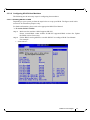
3.3.3.2.1 Enabling SR-IOV in BIOS
Depending on your system, perform the steps below to set up your BIOS. The figures used in this
section are for illustration purposes only.
For further information, please refer to the appropriate BIOS User Manual.
To enable SR-IOV in BIOS:
Step 1.
Make sure the machine’s BIOS supports SR-IOV.
Please, consult BIOS vendor website for SR-IOV supported BIOS versions list. Update
the BIOS version if necessary.
Step 2.
Follow BIOS vendor guidelines to enable SR-IOV according to BIOS User Manual.
For example:
a. Enable SR-IOV.
Mellanox Technologies
43
Rev 1.21
b. Enable “Intel Virtualization Technologhy” Support
For further details, please refer to the vendor's website.
Mellanox Technologies
44
Rev 1.21
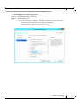
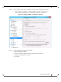
3.3.3.2.2 Installing Hypervisor Operating System (SR-IOV Ethernet Only)
To install Hypervisor Operating System:
Step 1.
Install Windows Server 2012 R2
Step 2.
Install Hyper-V role:
•
Go to: Server Manager -> Manage -> Add Roles and Features and set the following:
•
Installation Type -> Role-based or Feature-based Installation
•
Server Selection -> Select a server fro the server pool
•
Server Roles -> Hyper-V (see figures below)
Mellanox Technologies
45
Rev 1.21
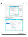
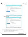
Step 3.
Install Hyper-V Management Tools.
Features - > Remote Server Administration Tools -> Role Administration Tools ->
Hyper-V Administration Tool.
Mellanox Technologies
46
Rev 1.21
Step 4.
Confirm the installation
Step 5.
Click Install
Step 6.
Reboot the system.
3.3.3.2.3 Verifying SR-IOV Support within the Host Operating System (SR-IOV Ethernet Only)
To verify that the system is properly configured for SR-IOV:
Step 1.
Go to: Start-> Windows Powershell.
Mellanox Technologies
47
Rev 1.21
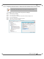
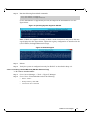
Step 2.
Run the following PowerShell commands.
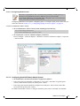
PS $ (Get-VmHost).IovSupport
PS $ (Get-VmHost).IovSupportReasons
In case that SR-IOV is supported by the OS, the output in the PowerShell is as in the
figure below.
Figure 5: Operating System Supports SR-IOV
Note: If BIOS was updated according to BIOS vendor instructions and you see the message displayed in the figure below, update the registry configuration as described in the
(Get-VmHost).IovSupportReasons message.
Figure 6: SR-IOV Support
Step 3.
Reboot
Step 4.
Verify the system is configured correctly for SR-IOV as described in Steps 1/2.
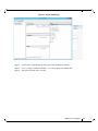
3.3.3.2.4 Creating a Virtual Machine (SR-IOV Ethernet Only)
To create a virtual machine
Step 1.
Go to: Server Manager -> Tools -> Hyper-V Manager.
Step 2.
Go to: New->Virtual Machine and set the following:
•
Name: <name>
•
Startup memory: 4096 MB
•
Connection: Not Connected
Mellanox Technologies
48
Rev 1.21
Figure 7: Hyper-V Manager
Step 3.
Connect the virtual hard disk in the New Virtual Machine Wizard.
Step 4.
Go to: Connect Virtual Hard Disk -> Use an existing virtual hard disk.
Step 5.
Select the location of the vhd file.
Mellanox Technologies
49
Rev 1.21
Figure 8: Connect Virtual Hard Disk
3.3.3.3 Configuring Mellanox Network Adapter for SR-IOV
The following are the steps for configuring Mellanox Network Adapter for SR-IOV:
3.3.3.3.1 Enabling SR-IOV in Firmware
For non-Mellanox (OEM) branded cards you may need to download and install the new firmware. For the latest OEM firmware, please go to:
http://www.mellanox.com/page/oem_firmware_download
As of firmware version 2.31.5000, SR-IOV can be enabled and managed by using the mlxconfig
too. For older firmware versions, use the flint tool.
To enable SR-IOV using mlxconfig:
mlxconfig is part of MFT tools used to simplify firmware configuration. The tool is available
with MFT tools 3.6.0 or higher.
Step 1.
Download MFT for Windows.
www.mellanox.com > Products > Software > Firmware Tools
Step 2.
Get the device ID (look for the “_pciconf” string in the output).
> mst status
Mellanox Technologies
50
Rev 1.21
Example:
MST devices:
-----------mt4115_pciconf0
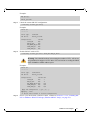
Step 3.
Check the current SR-IOV configuration.
> mlxconfig -d mt4115_pciconf0 q
Example:
Device #1:
---------Device type:
PCI device:
ConnectX4
mt4115_pciconf0
Configurations:
SRIOV_EN
NUM_OF_VFS
WOL_MAGIC_EN_P2
LINK_TYPE_P1
LINK_TYPE_P2
Step 4.
Current
N/A
N/A
N/A
N/A
N/A
Enable SR-IOV with 16 VFs.
> mlxconfig -d mt4115_pciconf0 s SRIOV_EN=1 NUM_OF_VFS=16
Warning: Care should be taken in increasing the number of VFs. All servers
are guaranteed to support 16 VFs. More VFs can lead to exceeding the BIOS
limit of MMIO available address space.
Example:
Device #1:
---------Device type:
PCI device:
ConnectX3Pro
mt4115_pciconf0
Configurations:
SRIOV_EN
NUM_OF_VFS
WOL_MAGIC_EN_P2
LINK_TYPE_P1
LINK_TYPE_P2
Current
N/A
N/A
N/A
N/A
N/A
New
1
16
N/A
N/A
N/A
Apply new Configuration? ? (y/n) [n] : y
Applying... Done!
-I- Please reboot machine to load new configurations.
Step 5.
Power cycle the machine (After the reboot, continue to Section 3.3.3.3.2, “Enabling SRIOV in Mellanox WinOF-2 Package (Ethernet SR-IOV Only)”, on page 52).
Mellanox Technologies
51
Rev 1.21
3.3.3.3.2 Enabling SR-IOV in Mellanox WinOF-2 Package (Ethernet SR-IOV Only)
To enable SR-IOV in Mellanox WinOF-2 Package
Step 1.
Install Mellanox WinOF-2 package that supports SR-IOV.
Step 2.
Set the Execution Policy:
PS $ Set-ExecutionPolicy AllSigned
Step 3.
Enable SR-IOV through Powershell:
New-NetAdapterAdvancedProperty -Name "Network Adapter" -RegistryKeyword *SRIOV -RegistryValue 1 -RegistryDataType REG_SZ
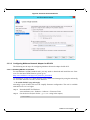
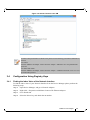
3.3.3.4 Configuring Operating Systems
3.3.3.4.1 Configuring Virtual Machine Networking (Ethernet SR-IOV Only)
To configure Virtual Machine networking:
Step 1.
Create an SR-IOV-enabled Virtual Switch over Mellanox Ethernet Adapter.
Go to: Start -> Server Manager -> Tools -> Hyper-V Manager
In the Hyper-V Manager: Actions -> Virtual SwitchManager -> External->
Create Virtual Switch
Step 2.
Set the following:
•
Name:
•
External network:
•
Enable single-root I/O virtualization (SR-IOV)
Mellanox Technologies
52
Rev 1.21
Figure 9: Virtual Switch with SR-IOV
Step 3.
Click Apply.
Step 4.
Click OK.
Mellanox Technologies
53
Rev 1.21
Step 5.
Add a VMNIC connected to a Mellanox vSwitch in the VM hardware settings:
•
Under Actions, go to Settings -> Add New Hardware-> Network Adapter-> OK.
•
In “Virtual Switch” dropdown box, choose Mellanox SR-IOV Virtual Switch.
Figure 10: Adding a VMNIC to a Mellanox v-Switch
Step 6.
Enable the SR-IOV for Mellanox VMNIC:
1. Open VM settings Wizard.
2. Open the Network Adapter and choose Hardware Acceleration.
3. Tick the “Enable SR-IOV” option.
4. Click OK.
Mellanox Technologies
54
Rev 1.21
Figure 11: Enable SR-IOV on VMNIC
Step 7.
Start and connect to the Virtual Machine:
Select the newly created Virtual Machine and go to: Actions panel-> Connect.
In the virtual machine window go to: Actions-> Start
Step 8.
Copy the WinOF driver package to the VM using Mellanox VMNIC IP address.
Step 9.
Install WinOF driver package on the VM.
Step 10. Reboot the VM at the end of installation.
Step 11. Verify that Mellanox Virtual Function appears in the device manager.
Mellanox Technologies
55
Rev 1.21
Figure 12: Virtual Function in the VM
To achieve best performance on SR-IOV VF, please run the following powershell commands on
the host:
For 10Gbe:
PS $ Set-VMNetworkAdapter -Name "Network Adapter" -VMName vm1 -IovQueuePairsRequested 4
For 40Gbe and 56Gbe:
PS $ Set-VMNetworkAdapter -Name "Network Adapter" -VMNamConnectX®-4 Lxe vm1 -IovQueuePairsRequested 8
3.4
Configuration Using Registry Keys
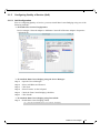
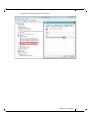
3.4.1
Finding the Index Value of the Network Interface
To find the index value of your Network Interface from the Device Manager please perform the
following steps:
Step 1.
Open Device Manager, and go to Network Adapters.
Step 2.
Right click ->Properties on Mellanox Connect-X® Ethernet Adapter.
Step 3.
Go to Details tab.
Step 4.
Select the Driver key, and obtain the nn number.
Mellanox Technologies
56
Rev 1.21
In the below example, the index equals 0010
Mellanox Technologies
57
Rev 1.21
3.4.2
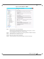
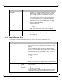
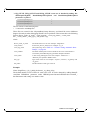
Basic Registry Keys
This group contains the registry keys that control the basic operations of the NIC
Value Name
*JumboPacket
Default Value
1514
Description
The maximum size of a frame (or a packet) that can be sent
over the wire. This is also known as the maximum transmission unit (MTU). The MTU may have a significant impact on
the network's performance as a large packet can cause high
latency. However, it can also reduce the CPU utilization and
improve the wire efficiency. The standard Ethernet frame
size is 1514 bytes, but Mellanox drivers support wide range
of packet sizes.
The valid values are:
•
Ethernet: 600 up to 9600
Note: All the devices across the network (switches and routers) should support the same frame size. Be aware that different network devices calculate the frame size differently.
Some devices include the header, i.e. information in the
frame size, while others do not.
Mellanox adapters do not include Ethernet header information in the frame size. (i.e when setting *JumboPacket to
1500, the actual frame size is 1514).
*ReceiveBuffers
512
The number of packets each ring receives. This parameter
affects the memory consumption and the performance.
Increasing this value can enhance receive performance, but
also consumes more system memory.
In case of lack of received buffers (dropped packets or out of
order received packets), you can increase the number of
received buffers.
The valid values are 256 up to 4096.
*TransmitBuffers
2048
The number of packets each ring sends. Increasing this value
can enhance transmission performance, but also consumes
system memory.
The valid values are 256 up to 4096.
*SpeedDuplex
7
The Speed and Duplex settings that a device supports. This
registry key should not be changed and it can be used to
query the device capability. Mellanox ConnectX device is set
to 7 meaning10Gbps and Full Duplex.
Note: Default value should not be modified.
Mellanox Technologies
58
Rev 1.21
Value Name
RxIntModerationProfile
Default Value
2
Description
Enables the assignment of different interrupt moderation profiles for receive completions. Interrupt moderation can have
a great effect on optimizing network throughput and CPU
utilization.
The valid values are:
•
•
•
TxIntModerationProfile
1
0: Low Latency
Implies higher rate of interrupts to achieve better latency, or to
handle scenarios where only a small number of streams are
used.
1: Moderate
Interrupt moderation is set to midrange defaults to allow maximum throughput at minimum CPU utilization for common scenarios.
2: Aggressive
Interrupt moderation is set to maximal values to allow maximum throughput at minimum CPU utilization, for more intensive, multi-stream scenarios.
Enables the assignment of different interrupt moderation profiles for send completions. Interrupt moderation can have
great effect on optimizing network throughput and CPU utilization.
The valid values are:
•
•
•
0: Low Latency
Implies higher rate of interrupts to achieve better latency, or to
handle scenarios where only a small number of streams are
used.
1: Moderate
Interrupt moderation is set to midrange defaults to allow maximum throughput at minimum CPU utilization for common scenarios.
2: Aggressive
Interrupt moderation is set to maximal values to allow maximum throughput at minimum CPU utilization for more intensive, multi-stream scenarios.
Mellanox Technologies
59
Rev 1.21
3.4.3
Off-load Registry Keys
This group of registry keys allows the administrator to specify which TCP/IP offload settings are
handled by the adapter rather than by the operating system.
Enabling offloading services increases transmission performance. Due to offload tasks (such as
checksum calculations) performed by adapter hardware rather than by the operating system (and,
therefore, with lower latency). In addition, CPU resources become more available for other tasks.
Value Name
*LsoV1IPv4
Default Value
1
Description
Large Send Offload Version 1 (IPv4).
The valid values are:
•
•
*LsoV2IPv4
1
Large Send Offload Version 2 (IPv4).
The valid values are:
•
•
*LsoV2IPv6
1
64000
0: disable
1: enable
Large Send Offload Version 2 (IPv6).
The valid values are:
•
•
LSOSize
0: disable
1: enable
0: disable
1: enable
The maximum number of bytes that the TCP/IP stack can
pass to an adapter in a single packet.
This value affects the memory consumption and the NIC performance.
The valid values are MTU+1024 up to 64000.
Note: This registry key is not exposed to the user via the UI.
If LSOSize is smaller than MTU+1024, LSO will be disabled.
LSOMinSegment
2
The minimum number of segments that a large TCP packet
must be divisible by, before the transport can offload it to a
NIC for segmentation.
The valid values are 2 up to 32.
Note: This registry key is not exposed to the user via the UI.
LSOTcpOptions
1
Enables that the miniport driver to segment a large TCP
packet whose TCP header contains TCP options.
The valid values are:
•
•
0: disable
1: enable
Note: This registry key is not exposed to the user via the UI.
Mellanox Technologies
60
Rev 1.21
Value Name
LSOIpOptions
Default Value
1
Description
Enables its NIC to segment a large TCP packet whose IP
header contains IP options.
The valid values are:
•
•
0: disable
1: enable
Note: This registry key is not exposed to the user via the UI.
*IPChecksumOffloadIPv4
3
Specifies whether the device performs the calculation of IPv4
checksums.
The valid values are:
•
•
•
•
*TCPUDPChecksumOffloadIPv4
3
Specifies whether the device performs the calculation of TCP
or UDP checksum over IPv4.
The valid values are:
•
•
•
•
*TCPUDPChecksumOffloadIPv6
3
0: (disable)
1: (Tx Enable)
2: (Rx Enable)
3: (Tx and Rx enable)
0: (disable)
1: (Tx Enable)
2: (Rx Enable)
3: (Tx and Rx enable)
Specifies whether the device performs the calculation of TCP
or UDP checksum over IPv6.
The valid values are:
•
•
•
•
0: (disable)
1: (Tx Enable)
2: (Rx Enable)
3: (Tx and Rx enable)
Mellanox Technologies
61
Rev 1.21
3.4.4
Performance Registry Keys
This group of registry keys configures parameters that can improve adapter performance.
Value Name
RecvCompletionMethod
Default Value
1
Description
Sets the completion methods of the receive packets,
and it affects network throughput and CPU utilization.
The supported methods are:
•
•
Polling - increases the CPU utilization, because the system polls the received rings for incoming packets; however, it may increase the network bandwidth since the
incoming packet is handled faster.
Adaptive - combines the interrupt and polling methods
dynamically, depending on traffic type and network
usage.
The valid values are:
•
•
*InterruptModeration
1
Sets the rate at which the controller moderates or
delays the generation of interrupts, making it possible
to optimize network throughput and CPU utilization.
When disabled, the interrupt moderation of the system
generates an interrupt when the packet is received. In
this mode, the CPU utilization is increased at higher
data rates, because the system must handle a larger
number of interrupts. However, the latency is
decreased, since that packet is processed more quickly.
When interrupt moderation is enabled, the system
accumulates interrupts and sends a single interrupt
rather than a series of interrupts. An interrupt is generated after receiving 5 packets or after the passing of 10
micro seconds from receiving the first packet.
The valid values are:
•
•
RxIntModeration
2
0: polling
1: adaptive
0: disable
1: enable
Sets the rate at which the controller moderates or
delays the generation of interrupts, making it possible
to optimize network throughput and CPU utilization.
The default setting (Adaptive) adjusts the interrupt
rates dynamically, depending on traffic type and network usage. Choosing a different setting may improve
network and system performance in certain configurations.
The valid values are:
•
•
1: static
2: adaptive
The interrupt moderation count and time are configured
dynamically, based on traffic types and rate.
Mellanox Technologies
62
Rev 1.21
Value Name
*RSS
Default Value
1
Description
Sets the driver to use Receive Side Scaling (RSS)
mode to improve the performance of handling incoming packets. This mode allows the adapter port to utilize the multiple CPUs in a multi-core system for
receiving incoming packets and steering them to their
destination. RSS can significantly improve the number
of transactions per second, the number of connections
per second, and the network throughput.
This parameter can be set to one of two values:
•
•
1: enable (default)
Sets RSS Mode.
0: disable
The hardware is configured once to use the Toeplitz
hash function and the indirection table is never changed.
Note: the I/O Acceleration Technology (IOAT) is not
functional in this mode.
ReturnPacketThreshold
341
The allowed number of free received packets on the
rings. Any number above it will cause the driver to
return the packet to the hardware immediately.
When the value is set to 0, the adapter uses 2/3 of the
received ring size.
The valid values are: 0 to 4096.
Note: This registry value is not exposed via the UI.
NumTcb
16
The number of send buffers that the driver allocates
for sending purposes. Each buffer is in LSO size, if
LSO is enabled, or in MTU size, otherwise.
The valid values are 1 up to 64.
Note: This registry value is not exposed via the UI.
ThreadPoll
10000
The number of cycles that should be passed without
receiving any packet before the polling mechanism
stops when using polling completion method for
receiving. Afterwards, receiving new packets will generate an interrupt that reschedules the polling mechanism.
The valid values are 0 up to 200000.
Note: This registry value is not exposed via the UI.
Mellanox Technologies
63
Rev 1.21
Value Name
AverageFactor
Default Value
16
Description
The weight of the last polling in the decision whether
to continue the polling or give up when using polling
completion method for receiving.
The valid values are 0 up to 256.
Note: This registry value is not exposed via the UI.
AveragePollThreshold
10
The average threshold polling number when using
polling completion method for receiving. If the average number is higher than this value, the adapter continues to poll.
The valid values are 0 up to 1000.
Note: This registry value is not exposed via the UI.
ThisPollThreshold
100
The threshold number of the last polling cycle when
using polling completion method for receiving. If the
number of packets received in the last polling cycle is
higher than this value, the adapter continues to poll
The valid values are 0 up to 1000.
Note: This registry value is not exposed via the UI.
VlanId
0
Enables packets with VlanId. It is used when no team
intermediate driver is used.
The valid values are:
•
•
0: disable
No Vlan Id is passed.
1-4095
Valid Vlan Id that will be passed.
Note: This registry value is only valid for Ethernet.
*NumRSSQueues
8
The maximum number of the RSS queues that the
device should use.
Note: This registry key is only in Windows Server
2012 and above.
Mellanox Technologies
64
Rev 1.21
Value Name
BlueFlame
Default Value
Description
1
The latency-critical Send WQEs to the device. When a
BlueFlame is used, the WQEs are written directly to
the PCI BAR of the device (in addition to memory), so
that the device may handle them without having to
access memory, thus shortening the execution latency.
For best performance, it is recommended to use the
BlueFlame when the HCA is lightly loaded. For highbandwidth scenarios, it is recommended to use regular
posting (without BlueFlame).
The valid values are:
•
•
0: disable
1: enable
Note: This registry value is not exposed via the UI.
*MaxRSSProcessors
8
The maximum number of RSS processors.
Note: This registry key is only in Windows Server
2012 and above.
3.4.5
Ethernet Registry Keys
The following section describes the registry keys that are only relevant to Ethernet driver.
Value Name
RoceMaxFrameSize
Default Value
1024
Description
The maximum size of a frame (or a packet) that can be sent
by the RoCE protocol (a.k.a Maximum Transmission Unit
(MTU).
Using larger RoCE MTU will improve the performance;
however, one must ensure that the entire system, including
switches, supports the defined MTU.
Ethernet packet uses the general MTU value, whereas the
RoCE packet uses the RoCE MTU
The valid values are:
•
•
•
•
256
512
1024
2048
Note: This registry key is supported only in Ethernet drivers.
*PriorityVLANTag
3 (Packet Priority &
VLAN
Enabled)
Enables sending and receiving IEEE 802.3ac tagged frames,
which include:
•
•
802.1p QoS (Quality of Service) tags for priority-tagged packets.
802.1Q tags for VLANs.
When this feature is enabled, the Mellanox driver supports
sending and receiving a packet with VLAN and QoS tag.
Mellanox Technologies
65
Rev 1.21
Value Name
PromiscuousVlan
Default Value
0
Description
Specifies whether a promiscuous VLAN is enabled or not.
When this parameter is set, all the packets with VLAN tags
are passed to an upper level without executing any filtering.
The valid values are:
•
•
0: disable
1: enable
Note: This registry value is not exposed via the UI.
3.4.5.1 Flow Control Options
This group of registry keys allows the administrator to control the TCP/IP traffic by pausing
frame transmitting and/or receiving operations. By enabling the Flow Control mechanism, the
adapters can overcome any TCP/IP issues and eliminate the risk of data loss.
Value Name
*FlowControl
Default Value
0
Description
When Rx Pause is enabled, the receiving adapter generates a
flow control frame when its received queue reaches a predefined limit. The flow control frame is sent to the sending
adapter.
When TX Pause is enabled, the sending adapter pauses the
transmission if it receives a flow control frame from a link
partner.
The valid values are:
•
•
•
•
0: Flow control is disabled
1: Tx Flow control is Enabled
2: Rx Flow control is enabled
3: Rx & Tx Flow control is enabled
3.4.5.2 VMQ Options
This section describes the registry keys that are used to control the NDIS Virtual Machine Queue
(VMQ). VMQ is supported by WinOF-2 and allows a performance boost for Hyper-V VMs.
For more details about VMQ please refer to Microsoft web site,
http://msdn.microsoft.com/en-us/library/windows/hardware/ff571034(v=vs.85).aspx
Value Name
*VMQ
Default Value
1
Description
The support for the virtual machine queue (VMQ) features of
the network adapter.
The valid values are:
•
•
1: enable
0: disable
Mellanox Technologies
66
Rev 1.21
Value Name
*RssOrVmqPreference
Default Value
0
Description
Specifies whether VMQ capabilities should be enabled
instead of receive-side scaling (RSS) capabilities.
The valid values are:
•
•
0: Report RSS capabilities
1: Report VMQ capabilities
Note: This registry value is not exposed via the UI.
*VMQVlanFiltering
1
Specifies whether the device enables or disables the ability to
filter network packets by using the VLAN identifier in the
media access control (MAC) header.
The valid values are:
•
•
3.4.6
0: disable
1: enable
Network Direct Interface
The Network Direct Interface (NDI) architecture provides application developers with a networking interface that enables zero-copy data transfers between applications, kernel-bypass I/O
generation and completion processing, and one-sided data transfer operations.
NDI is supported by Microsoft and is the recommended method to write an RDMA application.
NDI exposes the advanced capabilities of the Mellanox networking devices and allows applications to leverage advances of RDMA.
Both RoCE and InfiniBand (IB) can implement NDI.
For further information please refer to:
http://msdn.microsoft.com/en-us/library/cc904397(v=vs.85).aspx
Mellanox Technologies
67
Rev 1.21
3.5
Performance Tuning and Counters
For further information on WinOF-2 performance, please refer to the Performance Tuning Guide
for Mellanox Network Adapters.
This section describes how to modify Windows registry parameters in order to improve performance.
Please note that modifying the registry incorrectly might lead to serious problems, including the
loss of data, system hang, and you may need to reinstall Windows. As such it is recommended to
back up the registry on your system before implementing recommendations included in this section. If the modifications you apply lead to serious problems, you will be able to restore the original
registry state. For more details about backing up and restoring the registry, please visit www.microsoft.com.
3.5.1
General Performance Optimization and Tuning
To achieve the best performance for Windows, you may need to modify some of the Windows
registries.
3.5.1.1 Registry Tuning
The registry entries that may be added/changed by this “General Tuning” procedure are:
Under HKEY_LOCAL_MACHINE\SYSTEM\CurrentControlSet\Services\Tcpip\Parameters:
•
Disable TCP selective acks option for better cpu utilization:
SackOpts, type REG_DWORD, value set to 0.
Under HKEY_LOCAL_MACHINE\SYSTEM\CurrentControlSet\Services\AFD\Parameters:
•
Enable fast datagram sending for UDP traffic:
FastSendDatagramThreshold, type REG_DWORD, value set to 64K.
Under HKEY_LOCAL_MACHINE\SYSTEM\CurrentControlSet\Services\Ndis\Parameters:
•
Set RSS parameters:
RssBaseCpu, type REG_DWORD, value set to 1.
3.5.1.2 Enable RSS
Enabling Receive Side Scaling (RSS) is performed by means of the following command:
“netsh int tcp set global rss = enabled”
3.5.1.3 Improving Live Migration
In order to improve live migration over SMB direct performance, please set the following registry key to 0 and reboot the machine:
HKEY_LOCAL_MACHINE\System\CurrentControlSet\Services\LanmanServer\Parameters\RequireSecuritySignature
Mellanox Technologies
68
Rev 1.21
3.5.2
Application Specific Optimization and Tuning
3.5.2.1 Ethernet Performance Tuning
The user can configure the Ethernet adapter by setting some registry keys. The registry keys may
affect Ethernet performance.
To improve performance, activate the performance tuning tool as follows:
Step 1.
Start the "Device Manager" (open a command line window and enter: devmgmt.msc).
Step 2.
Open "Network Adapters".
Step 3.
Right click the relevant Ethernet adapter and select Properties.
Step 4.
Select the "Advanced" tab
Step 5.
Modify performance parameters (properties) as desired.
3.5.2.1.1 Performance Known Issues
3.5.3
•
On Intel I/OAT supported systems, it is highly recommended to install and enable the
latest I/OAT driver (download from www.intel.com).
•
With I/OAT enabled, sending 256-byte messages or larger will activate I/OAT. This will
cause a significant latency increase due to I/OAT algorithms. On the other hand,
throughput will increase significantly when using I/OAT.
Tunable Performance Parameters
The following is a list of key parameters for performance tuning.
•
Jumbo Packet
The maximum available size of the transfer unit, also known as the Maximum Transmission
Unit (MTU). The MTU of a network can have a substantial impact on performance. A 4K
MTU size improves performance for short messages, since it allows the OS to coalesce many
small messages into a large one.
• Valid MTU values range for an Ethernet driver is between 614 and 9614.
All devices on the same physical network, or on the same logical network, must have
the same MTU.
•
Receive Buffers
The number of receive buffers (default 1024).
•
Send Buffers
The number of sent buffers (default 2048).
•
Performance Options
Configures parameters that can improve adapter performance.
• Interrupt Moderation
Moderates or delays the interrupts’ generation. Hence, optimizes network throughput and CPU utilization (default Enabled).
Mellanox Technologies
69
Rev 1.21
•
When the interrupt moderation is enabled, the system accumulates interrupts and sends a single interrupt
rather than a series of interrupts. An interrupt is generated after receiving 5 packets or after 10ms from
the first packet received. It improves performance and reduces CPU load however, it increases latency.
•
When the interrupt moderation is disabled, the system generates an interrupt each time a packet is
received or sent. In this mode, the CPU utilization data rates increase, as the system handles a larger
number of interrupts. However, the latency decreases as the packet is handled faster.
• Receive Side Scaling (RSS Mode)
Improves incoming packet processing performance. RSS enables the adapter port to utilize the
multiple CPUs in a multi-core system for receiving incoming packets and steering them to the designated destination. RSS can significantly improve the number of transactions, the number of connections per second, and the network throughput.
This parameter can be set to one of the following values:
•
Enabled (default): Set RSS Mode
•
Disabled: The hardware is configured once to use the Toeplitz hash function, and the indirection table is
never changed.
IOAT is not used while in RSS mode.
•
Receive Completion Method
Sets the completion methods of the received packets, and can affect network throughput and CPU utilization.
•
Polling Method
Increases the CPU utilization as the system polls the received rings for the incoming packets. However, it
may increase the network performance as the incoming packet is handled faster.
•
Interrupt Method
Optimizes the CPU as it uses interrupts for handling incoming messages. However, in certain scenarios it
can decrease the network throughput.
•
Adaptive (Default Settings)
A combination of the interrupt and polling methods dynamically, depending on traffic type and network
usage. Choosing a different setting may improve network and/or system performance in certain configurations.
• Interrupt Moderation RX Packet Count
Number of packets that need to be received before an interrupt is generated on the receive side
(default 5).
• Interrupt Moderation RX Packet Time
Maximum elapsed time (in usec) between the receiving of a packet and the generation of an interrupt, even if the moderation count has not been reached (default 10).
• Rx Interrupt Moderation Type
Sets the rate at which the controller moderates or delays the generation of interrupts making it possible to optimize network throughput and CPU utilization. The default setting (Adaptive) adjusts
the interrupt rates dynamically depending on the traffic type and network usage. Choosing a different setting may improve network and system performance in certain configurations.
• Send completion method
Mellanox Technologies
70
Rev 1.21
Sets the completion methods of the Send packets and it may affect network throughput and CPU
utilization.
• Interrupt Moderation TX Packet Count
Number of packets that need to be sent before an interrupt is generated on the send side (default 0).
• Interrupt Moderation TX Packet Time
Maximum elapsed time (in usec) between the sending of a packet and the generation of an interrupt even if the moderation count has not been reached (default 0).
•
Offload Options
Allows you to specify which TCP/IP offload settings are handled by the adapter rather than the
operating system.
Enabling offloading services increases transmission performance as the offload tasks are performed by the adapter hardware rather than the operating system. Thus, freeing CPU resources
to work on other tasks.
• IPv4 Checksums Offload
Enables the adapter to compute IPv4 checksum upon transmit and/or receive instead of the CPU
(default Enabled).
• TCP/UDP Checksum Offload for IPv4 packets
Enables the adapter to compute TCP/UDP checksum over IPv4 packets upon transmit and/or
receive instead of the CPU (default Enabled).
• TCP/UDP Checksum Offload for IPv6 packets
Enables the adapter to compute TCP/UDP checksum over IPv6 packets upon transmit and/or
receive instead of the CPU (default Enabled).
• Large Send Offload (LSO)
Allows the TCP stack to build a TCP message up to 64KB long and sends it in one call down the
stack. The adapter then re-segments the message into multiple TCP packets for transmission on the
wire with each pack sized according to the MTU. This option offloads a large amount of kernel
processing time from the host CPU to the adapter.
3.5.4
Adapter Proprietary Performance Counters
Proprietary Performance Counters are used to provide information on Operating System, application, service or the drivers' performance. Counters can be used for different system debugging
purposes, help to determine system bottlenecks and fine-tune system and application performance. The Operating System, network, and devices provide counter data that the application
can consume to provide users with a graphical view of the system’s performance quality. WinOF
counters hold the standard Windows CounterSet API that includes:
•
Network Interface
•
RDMA activity
•
SMB Direct Connection
Mellanox Technologies
71
Rev 1.21
3.5.4.0.1 RDMA Activity
RDMA Activity counter set consists of NDK performance counters. These performance counters
allow you to track Network Direct Kernel (RDMA) activity, including traffic rates, errors, and
control plane activity.
Table 8 - RDMA Activity
RDMA Activity Counters
Description
RDMA Accepted Connections
The number of inbound RDMA connections established.
RDMA Active Connections
The number of active RDMA connections.
RDMA Completion Queue
Errors
This counter is not supported, and always is set to zero.
RDMA Connection Errors
The number of established connections with an error before a
consumer disconnected the connection.
RDMA Failed Connection
Attempts
The number of inbound and outbound RDMA connection
attempts that failed.
RDMA Inbound Bytes/sec
The number of bytes for all incoming RDMA traffic. This
includes additional layer two protocol overhead.
RDMA Inbound Frames/sec
The number, in frames, of layer two frames that carry incoming
RDMA traffic.
RDMA Initiated Connections
The number of outbound connections established.
RDMA Outbound Bytes/sec
The number of bytes for all outgoing RDMA traffic. This
includes additional layer two protocol overhead.
RDMA Outbound Frames/sec
The number, in frames, of layer two frames that carry outgoing
RDMA traffic.
Mellanox Technologies
72
Rev 1.21
4
Utilities
4.1
Fabric Performance Utilities
The performance utilities described in this chapter are intended to be used as a performance
micro-benchmark. They support both InfiniBand and RoCE.
For further information on the following tools, please refer to the help text of the tool by
running the --help command line parameter.
Table 9 - Fabric Performance Utilities
Utility
Description
nd_write_bw
This test is used for performance measuring of RDMA-Write requests
in Microsoft Windows Operating Systems. nd_write_bw is performance oriented for RDMA-Write with maximum throughput, and runs
over Microsoft's NetworkDirect standard. The level of customizing for
the user is relatively high. User may choose to run with a customized
message size, customized number of iterations, or alternatively, customized test duration time. nd_write_bw runs with all message sizes
from 1B to 4MB (powers of 2), message inlining, CQ moderation.
nd_write_lat
This test is used for performance measuring of RDMA-Write requests
in Microsoft Windows Operating Systems. nd_write_lat is performance oriented for RDMA-Write with minimum latency, and runs over
Microsoft's NetworkDirect standard. The level of customizing for the
user is relatively high. User may choose to run with a customized message size, customized number of iterations, or alternatively, customized
test duration time. nd_write_lat runs with all message sizes from 1B to
4MB (powers of 2), message inlining, CQ moderation.
nd_read_bw
This test is used for performance measuring of RDMA-Read requests
in Microsoft Windows Operating Systems. nd_read_bw is performance
oriented for RDMA-Read with maximum throughput, and runs over
Microsoft's NetworkDirect standard. The level of customizing for the
user is relatively high. User may choose to run with a customized message size, customized number of iterations, or alternatively, customized
test duration time. nd_read_bw runs with all message sizes from 1B to
4MB (powers of 2), message inlining, CQ moderation.
Mellanox Technologies
73
Rev 1.21
Utility
Description
nd_read_lat
This test is used for performance measuring of RDMA-Read requests
in Microsoft Windows Operating Systems. nd_read_lat is performance
oriented for RDMA-Read with minimum latency, and runs over Microsoft's NetworkDirect standard. The level of customizing for the user is
relatively high. User may choose to run with a customized message
size, customized number of iterations, or alternatively, customized test
duration time. nd_read_lat runs with all message sizes from 1B to 4MB
(powers of 2), message inlining, CQ moderation.
nd_send_bw
This test is used for performance measuring of Send requests in Microsoft Windows Operating Systems. nd_send_bw is performance oriented for Send with maximum throughput, and runs over Microsoft's
NetworkDirect standard. The level of customizing for the user is relatively high. User may choose to run with a customized message size,
customized number of iterations, or alternatively, customized test duration time. nd_send_bw runs with all message sizes from 1B to 4MB
(powers of 2), message inlining, CQ moderation.
nd_send_lat
This test is used for performance measuring of Send requests in Microsoft Windows Operating Systems. nd_send_lat is performance oriented
for Send with minimum latency, and runs over Microsoft's NetworkDirect standard. The level of customizing for the user is relatively high.
User may choose to run with a customized message size, customized
number of iterations, or alternatively, customized test duration time.
nd_send_lat runs with all message sizes from 1B to 4MB (powers of
2), message inlining, CQ moderation.
NTttcp
NTttcp is a Windows base testing application that sends and receives
TCP data between two or more endpoints. It is a Winsock-based port of
the ttcp tool that measures networking performance bytes/second.
To download the latest version of NTttcp (5.28), please refer to Microsoft website following the link below:
http://gallery.technet.microsoft.com/NTttcp-Version-528-Nowf8b12769
NOTE: This tool should be run from cmd only.
The following InfiniBand performance tests are deprecated and might be removed in
future releases.
Mellanox Technologies
74
Rev 1.21
4.2
Management Utilities
The management utilities described in this chapter are intended to be used to manage devices and
providers.
Table 10 - Management Utilities
Utility
ndinstall
4.3
Description
This utility is used to remove, install and list NetworkDirect providers.
Diagnostic Utilities
The diagnostic utilities described in this chapter provide means for debugging the connectivity
and status of devices in a fabric.
Table 11 - Diagnostic Utilities
Utility
MlxStat
Description
This utility displays information of Mellanox NIC attributes. It is the
equivalent utility to ibstat and vstat utilities in WinOF.
Mellanox Technologies
75
Rev 1.21
5
Troubleshooting
You may be able to easily resolve the issues described in this section. If a problem persists and
you are unable to resolve it, please contact your Mellanox representative or Mellanox Support at
[email protected].
5.1
Installation Related Troubleshooting
Table 12 - Installation Related Issues
Issue
Cause
The installation of
WinOF-2 fails with the
following error message:
An incorrect driver version
might have been installed,
e.g., you are trying to install
a 64-bit driver on a 32-bit
machine (or vice versa).
“This installation
package is not supported by this processor type. Contact
your product vendor".
5.1.1
Solution
Use the correct driver package according to the CPU architecture.
Installation Error Codes and Troubleshooting
5.1.1.1 Setup Return Codes
Table 13 - Setup Return Codes
Error Code
1603
1633
Description
Troubleshooting
Fatal error during installation
The installation package is not supported
on this platform.
Contact support
Make sure you are installing the
right package for your platform
For additional details on Windows installer return codes, please refer to:
http://support.microsoft.com/kb/229683
5.1.1.2 Firmware Burning Warning Codes
Table 14 - Firmware Burning Warning Codes
Error Code
Description
1004
1005
Failed to open the device
Could not find an image for at
least one device
1006
Found one device that has multiple
images
Found one device for which force
update is required
1007
Troubleshooting
Contact support
The firmware for your device was not
found. Please try to manually burn the
firmware.
Burn the firmware manually and select
the image you want to burn.
Burn the firmware manually with the
force flag.
Mellanox Technologies
76
Rev 1.21
Table 14 - Firmware Burning Warning Codes
Error Code
1008
Description
Troubleshooting
Found one device that has mixed
versions
The firmware version or the expansion
rom version does not match.
For additional details, please refer to the MFT User Manual:
http://www.mellanox.com > Products > Firmware Tools
5.1.1.3 Restore Configuration Warnings
Table 15 - Restore Configuration Warnings
Error Code
3
5.2
Description
Troubleshooting
Failed to restore the configuration
Please see log for more details and contact the
support team
Ethernet Related Troubleshooting
For further performance related information, please refer to the Performance Tuning Guide and
to Section 3.5, “Performance Tuning and Counters”, on page 68
Table 16 - Ethernet Related Issues
Issue
Cause
Solution
Low performance
Non-optimal system configuration might have
occurred.
See section “Performance Tuning and
Counters” on page 68. to take advantage
of Mellanox 10/40/56 GBit NIC performance.
The driver fails to start.
There might have been an
RSS configuration mismatch between the TCP
stack and the Mellanox
adapter.
1. Open the event log and look under
"System" for the "mlx5" source.
2. If found, enable RSS, run: "netsh
int tcp set global rss =
enabled".
or a less recommended suggestion (as it
will cause low performance):
• Disable RSS on the adapter, run:
"netsh int tcp set global rss
= no dynamic balancing".
Mellanox Technologies
77
Rev 1.21
Table 16 - Ethernet Related Issues
Issue
Cause
Solution
Look into the Event Viewer
to view the error.
• If the failure occurred due to unsupported mode type, refer to
Section 3.1.1, “Mode Configuration”
for the solution.
• If the solution isn't mentioned in
event viewer, disable and re-enable
"Mellanox ConnectX-4 Adapter
<X>" from the Device Manager display. If the failure resumes, please
refer to Mellanox support at
[email protected].
No connectivity to a
Fault Tolerance team
while using network
capture tools (e.g.,
Wireshark).
The network capture tool
might have captured the
network traffic of the nonactive adapter in the team.
This is not allowed since
the tool sets the packet filter
to "promiscuous", thus
causing traffic to be transferred on multiple interfaces.
Close the network capture tool on the
physical adapter card, and set it on the
team interface instead.
No Ethernet connectivity on 10Gb adapters
after activating Performance Tuning (part of
the installation).
A TcpWindowSize registry
value might have been
added.
• Remove the value key under
The driver fails to start
and a yellow sign
appears near the "Mellanox ConnectX-4
Adapter <X>" in the
Device Manager display. (Code 10)
HKEY_LOCAL_MACHINE\SYSTEM\CurrentControlSet\Services\Tcpip\Parameters\TcpWind
owSize
Or
• Set its value to 0xFFFF.
Packets are being lost.
The port MTU might have
been set to a value higher
than the maximum MTU
supported by the switch.
Change the MTU according to the maximum MTU supported by the switch.
NVGRE changes done
on a running VM, are
not propagated to the
VM.
The configuration changes
might not have taken effect
until the OS is restarted.
Stop the VM and afterwards perform
any NVGRE configuration changes on
the VM connected to the virtual switch.
Mellanox Technologies
78
Rev 1.21
5.3
Performance Related Troubleshooting
Table 17 - Performance Related Issues
5.3.1
Issue
Cause
Solution
Low performance issues
The OS profile might not be
configured for maximun
performace.
1. Go to "Power Options" in the "Control Panel". Make sure "Maximum
Performance" is set as the power
scheme
2. Reboot the machine.
General Diagnostic
Issue 1.
Issue 2.
Go to “Device Manager”, locate the Mellanox adapter that you are debugging, rightclick and choose “Properties” and go to the “Information” tab:
•
PCI Gen 1: should appear as "PCI-E 2.5 GT/s"
•
PCI Gen 2: should appear as "PCI-E 5.0 GT/s"
•
PCI Gen 3: should appear as "PCI-E 8.0 GT/s"
•
Link Speed: 56.0 Gbps / 40.0Gbps / 10.0Gbps / 100 Gbps
To determine if the Mellanox NIC and PCI bus can achieve their maximum speed, it's
best to run nd_send_bw in a loopback. On the same machine:
1. Run "start /b /affinity 0x1 nd_send_bw -S <IP_host>" where <IP_host> is the local
IP.
2. Run "start /b /affinity 0x2 nd_send_bw -C <IP_host>"
3. Repeat for port 2 with the appropriate IP.
4. On PCI Gen3 the expected result is around 5700MB/s
On PCI Gen2 the expected result is around 3300MB/s
Any number lower than that points to bad configuration or installation on the wrong PCI slot.
Malfunctioning QoS settings and Flow Control can be the cause as well.
Issue 3.
To determine the maximum speed between the two sides with the most basic test:
1. Run "nd_send_bw -S <IP_host1>" on machine 1 where <IP_host1> is the local IP.
2. Run "nd_send_bw -C <IP_host1>" on machine 2.
3. Results appear in Gb/s (Gigabits 2^30), and reflect the actual data that was trans-
ferred, excluding headers.
4. If these results are not as expected, the problem is most probably with one or more
of the following:
•
Old Firmware version.
•
Misconfigured Flow-control: Global pause or PFC is configured wrong on the hosts, routers andswitches. See Section 3.1.3,“RDMA over Converged Ethernet (RoCE),” on page 25
•
CPU/power options are not set to "Maximum Performance".
Mellanox Technologies
79
Rev 1.21
5.4
Virtualization Related Troubleshooting
Table 18 - Virtualization Related Issues
Issue
When enabling the
VMQ, in case NVGRE
offload is enabled, and a
teaming of two virtual
ports is performed, no
ping is detected
between the VMs and/
or ping is detected but
no establishing of TCP
connection is possible.
Cause
Might be missing critical
Microsoft updates.
Solution
Please refer to:
http://support.microsoft.com/kb/
2975719
“August 2014 update rollup for Windows server RT 8.1, Windows server
8.1, and Windows server 2012 R2” –
specifically, fixes.
Mellanox Technologies
80
Rev 1.21
5.5
Reported Driver Events
The driver records events in the system log of the Windows server event system which can be
used to identify, diagnose, and predict sources of system problems.
To see the log of events, open System Event Viewer as follows:
•
Right click on My Computer, click Manage, and then click Event Viewer.
OR
1. Click start-->Run and enter "eventvwr.exe".
2. In Event Viewer, select the system log.
The following events are recorded:
• Mellanox ConnectX-4 VPI Adapter <X> device has been requested for <Y> Virtual Functions (VFs), while it only supports <Z> VFs. Therefore, only <q> VFs will be allowed.
• Mellanox ConnectX-4 VPI Adapter <X> device has been configured to use RSS while
Windows' TCP RSS is disabled. This configuration prevents the initialization and enabling
of the port. You need to either enable Windows' TCP RSS, or configure the adapter's port
to disable RSS. For further details, see the README file under the documentation folder.
• Mellanox ConnectX-4 VPI Adapter <X>: Jumbo packet value read from registry (<Y>) is
greater than the value supported by FW (<Z>). Therefore use the maximum value supported by FW(<q>).
• Mellanox ConnectX-4 VPI Adapter <X>: Maximum MTU supported by FW
<L>.<Y>.<Z>(<q>) is smaller than the minimum value <K>.
• Mellanox ConnectX-4 VPI Adapter <X> device is successfully stopped.
• Mellanox ConnectX-4 VPI Adapter <X> device startup fails due to less than minimum
MSI-X vectors available.
• Mellanox ConnectX-4 VPI Adapter <X> device detects that the link is up, and has initiated a normal operation.
• Mellanox ConnectX-4 VPI Adapter <X> device detects that the link is down. This may
occur if the physical link is disconnected or damaged, or if the other end-port is down.
• Mellanox ConnectX-4 VPI Adapter <X>Mellanox ConnectX-4 VPI Adapter <X> device
configures not to use RSS. This configuration may significantly affect the network performance.
• Mellanox ConnectX-4 VPI Adapter <X> device reports an "Error event" on CQn #<Y>.
Since the event type is:<Z>, the NIC will be reset. (The issue is reported in Function
<K>).
• Mellanox ConnectX-4 VPI Adapter <X> device reports a send=<Y> "CQE error" on cqn
#<Z> qpn #<q> cqe_error->syndrome <K>, cqe_error->vendor_error_syndrome <L>,
Opcode <F>. Therefore, the NIC will be reset. (The issue is reported in Function <M>).
For more information refer to details.
• Mellanox ConnectX-4 VPI Adapter <X> device reports an "EQ stuck" on EQn <Y>.
Attempting recovery.
• Mellanox ConnectX-4 VPI Adapter <X> device reports a send completion handling timeout on TxQueue #<Y>. Attempting recovery. (The issue is reported in Function <Z>).
• Mellanox ConnectX-4 VPI Adapter <X> device reports a receive completion handling
timeout on RxQueue #<Y>. Attempting recovery. (The issue is reported in Function <Z>).
Mellanox Technologies
81
Rev 1.21
• Flow control on the device Mellanox ConnectX-4 VPI Adapter <X> wasn't enabled.
Therefore, RoCE cannot function properly. To resolve this issue, please make sure that
flow control is configured on both the hosts and switches in your network. For more
details, please refer to the user manual.
• Mellanox ConnectX-4 VPI Adapter <X> device is configured with a MAC address designated as a multicast address: <Y>.
Please configure the registry value NetworkAddress with another address, then restart the
driver.
• The miniport driver initiates reset on device Mellanox ConnectX-4 VPI Adapter <X>.
• NDIS initiates reset on device Mellanox ConnectX-4 VPI Adapter <X>.
• Reset on device Mellanox ConnectX-4 VPI Adapter <X> has finished.
• Mellanox ConnectX-4 VPI Adapter <X> has got:
•
vendor_id
<Y>
•
device_id
<Z>
•
subvendor_id <F>
•
subsystem_id <L>
•
HW revision
<M>
•
FW version
<R>.<G>.<Q>
•
port type
<N>
• Mellanox ConnectX-4 VPI Adapter <X>: QUERY_HCA_CAP command fails with error
<Y>.
The adapter card is dysfunctional.
Most likely a FW problem.
Please burn the last FW and restart the Mellanox ConnectX device.
• Mellanox ConnectX-4 VPI Adapter <X>: QUERY_ADAPTER command fails with error
<Y>.
The adapter card is dysfunctional.
Most likely a FW problem.
Please burn the last FW and restart the Mellanox ConnectX device.
• Mellanox ConnectX-4 VPI Adapter <X>: The number of allocated MSI-X vectors is less
than recommended. This may decrease the network performance.
The number of requested MSI-X vectors is: <Y> while the number of allocated MSI-X
vectors is: <Z>.
• Mellanox ConnectX-4 VPI Adapter <X>: FW command fails. op 0x<Y>, status 0x<Z>,
errno <F>, syndrome 0x<L>.
• Too many IPs in-use for RRoCE.
Mellanox ConnectX-4 VPI Adapter <X>: RRoCE supports only <Y> IPs per port.
Please reduce the number of IPs to use the new IPs.
• Mellanox ConnectX-4 VPI Adapter <X>: Driver startup fails because an insufficient number of Event Queues (EQs) is available.
(<Y> are required, <Z> are recommended, <M> are available)
• Mellanox ConnectX-4 VPI Adapter <X>: Execution of FW command fails. op 0x<Y>,
errno <Z>.
Mellanox Technologies
82
Rev 1.21
• Mellanox ConnectX-4 VPI Adapter <X>: Driver startup has failed due to unsupported
port type=<Y> configured on the device.
The driver supports Ethernet mode only, please refer to the Mellanox WinOF-2 User Manual for instructions on how to configure the correct mode.
• Mellanox ConnectX-4 VPI Adapter <X>: Driver startup fails because minimal driver
requirements are not supported by FW <Y>.<Z>.<L>.
FW reported:
•
rss_ind_tbl_cap
<Q>
•
vlan_cap
<M>
•
max_rqs
<F>
•
max_sqs
<N>
•
max_tirs
<O>
Please burn a firmware that supports the requirements and restart the Mellanox ConnectX device.
For additional information, please refer to Support information on http://mellanox.com.
• Mellanox ConnectX-4 VPI Adapter <X>: Driver startup fails because maximum flow
table size that is supported by FW <Y>.<Z>.<L> is too small (<K> entries).
Please burn a firmware that supports a greater flow table size and restart the Mellanox
ConnectX device. For additional information, please refer to Support information on http:/
/mellanox.com.
• Mellanox ConnectX-4 VPI Adapter <X>: Driver startup fails because required receive
WQE size is greater than the maximum WQEs size supported by FW <Y>.<Z>.<M>.
(<F> are required, <O> are supported)
• Mellanox ConnectX-4 VPI Adapter <X>: Driver startup fails because maximum WQE
size that is supported by FW <Y>.<L>.<M> is too small (<K>).
Please burn a firmware that supports a greater WQE size and restart the Mellanox ConnectX device. For additional information, please refer to Support information on http://
mellanox.com
• Mellanox ConnectX-4 VPI Adapter <X>: CQ moderation is not supported by FW
<Y>.<Z>.<L>.
• Mellanox ConnectX-4 VPI Adapter <X>: CQ to EQ remap is not supported by FW
<Y>.<Z>.<L>.
• Mellanox ConnectX-4 VPI Adapter <X>: VPort counters are not supported by FW
<Y>.<Z>.<L>.
• Mellanox ConnectX-4 VPI Adapter <X>: LSO is not supported by FW <Y>.<Z>.<L>.
• Mellanox ConnectX-4 VPI Adapter <X>: Checksum offload is not supported by FW
<Y>.<Z>.<L>.
• NDIS initiated reset on device Mellanox ConnectX-4 VPI Adapter <X> has failed.
• Mellanox
ConnectX-4
VPI
Adapter
<X>:
mstdump
%SystemRoot%\Temp\<Y>_<Z><L>_<M>_<F>_<O>.log was created after fatal error.
• Mellanox
ConnectX-4
VPI
Adapter
<X>:
mstdump
%SystemRoot%\Temp\<Y>_<Z><L>_<M>_<F>_<O>.log was created after OID request.
Mellanox Technologies
83
Rev 1.21
5.6
State Dumping
Upon several types of events, the drivers can produce a set of files reflecting the current state of
the adapter.
Automatic state dumps are done upon the following events:
Table 19 - Events Causing Automatic State Dumps
Event Type
Description
Provider
Defa
ult
Tag
CMD_ERR
Command failure or timeout on a command
Mlx5
On
c
EQ_STUCK
Driver decided that an event queue is stuck
Mlx5
On
e
TXCQ_STUCK
Driver decided that a transmit completion queue
is stuck
Mlx5
On
t
RXCQ_STUCK
Driver decided that a receive completion queue is
stuck
Mlx5
On
r
PORT_STATE
Adapter passed to “port down” state or “port
unknown” state
Mlx5
Off
p
ON_OID
User application asked to generate dump files
Mlx5
N/A
o
where
Provider
The driver creating the set of files.
Default
Whether or not the state dumps are created by default upon this event.
Tag
Part of the file name, used to identify the event that has triggered the
state dump.
Dump events can be enabled/disabled by adding DWORD32 parameters into HKLM\System\CurrnetControlSet\Services\mlx5\Parameters\Diag as follows:
Dump events can be disabled by adding MstDumpMode parameter as follows:
MstDumpMode
0
PORT_STATE events can be enabled by adding EnableDumpOnUnknownLink and
EnableDumpOnPortDown parameters as follows:
EnableDumpOnUnknownLink
EnableDumpOnPortDown
1
1
Mellanox Technologies
84
Rev 1.21
EQ_STUCK, TXCQ_STUCK and RXCQ_STUCK events can be disabled by adding DisableDumpOnEqStuck, DisableDumpOnTxCqStuck and DisableDumpOnRxCqStuck
parameters as follows:
DisableDumpOnTxCqStuck
DisableDumpOnTxCqStuck
DisableDumpOnRxCqStuck
1
1
1
The set consists of the following files:
•
3 consecutive mstdump files
These files are created in the %SystemRoot%\temp directory, and should be sent to Mellanox
Support for analysis when debugging WinOF2 driver problems. Their names have the following
format:<Driver_mode_of_work>_<card_location>_<event_tag_name>_<event_number>_<event_name>_<file_type>_<file_index>.log
where:
Driver_mode_of_work
The mode of driver work. For example: ‘SingleFunc’
card_location
In form bus_device_function, For example: 4_0_0
event_tag_name
One-symbol tag. See in Table 19 - “Events Causing Automatic State
Dumps,” on page 84
event_number
The index of dump files set and created for this event. This number is
restricted by the hidden Registry parameter DumpEventsNum
event_name
A short string naming the event. For example: ‘eth-down-1’ =
“Ethernet port1 passed to DOWN state”
file_type
Type of file in the set. For example: “crspace”, “fwtrace”, “eq_dump” and
“eq_print”
file_index
The file number of this type in the set
Example:
Name: SingleFunc_4_0_0_p000_eth-down-1_eq_dump_0.log
The default number of sets of files for each event is 20. It can be changed by adding DumpEventsNum DWORD32 parameter under HKLM\System\CurrnetControlSet\Services\mlx4_bus\Parameters and setting it to another value.
Mellanox Technologies
85
Rev 1.21
Appendix A: NVGRE Configuration Scripts Examples
The setup is as follow for both examples below:
Hypervisor
VM on
VM on
Hypervisor
VM on
VM on
A.1
mtlae14
mtlae14
mtlae14
mtlae15
mtlae15
mtlae15
=
=
=
=
=
=
"Port1", 192.168.20.114/24
mtlae14-005, 172.16.14.5/16,
mtlae14-006, 172.16.14.6/16,
"Port1", 192.168.20.115/24
mtlae15-005, 172.16.15.5/16,
mtlae15-006, 172.16.15.6/16,
Mac 00155D720100
Mac 00155D720101
Mac 00155D730100
Mac 00155D730101
Adding NVGRE Configuration to Host 14 Example
The following is an example of adding NVGRE to Host 14.
# On both sides
# vSwitch create command
# Note, that vSwitch configuration is persistent, no need to configure it after each
reboot
New-VMSwitch "VSwMLNX" -NetAdapterName "Port1" -AllowManagementOS $true
# Shut down VMs
Stop-VM -Name "mtlae14-005" -Force -Confirm
Stop-VM -Name "mtlae14-006" -Force -Confirm
# Connect VM to vSwitch (maybe you have to switch off VM before), doing manual does also
work
# Connect-VMNetworkAdapter -VMName " mtlae14-005" -SwitchName "VSwMLNX"
Add-VMNetworkAdapter -VMName "mtlae14-005" -SwitchName "VSwMLNX" -StaticMacAddress
"00155D720100"
Add-VMNetworkAdapter -VMName "mtlae14-006" -SwitchName "VSwMLNX" -StaticMacAddress
"00155D720101"
# ------- The commands from Step 2 - 4 are not persistent, Its suggested to create
script is running after each OS reboot
# Step 2. Configure a Subnet Locator and Route records on each Hyper-V Host (Host 1 and
Host 2) mtlae14 & mtlae15
New-NetVirtualizationLookupRecord -CustomerAddress 172.16.14.5 -ProviderAddress
192.168.20.114 -VirtualSubnetID 5001 -MACAddress "00155D720100" -Rule "TranslationMethodEncap"
New-NetVirtualizationLookupRecord -CustomerAddress 172.16.14.6 -ProviderAddress
192.168.20.114 -VirtualSubnetID 5001 -MACAddress "00155D720101" -Rule "TranslationMethodEncap"
New-NetVirtualizationLookupRecord -CustomerAddress 172.16.15.5 -ProviderAddress
192.168.20.115 -VirtualSubnetID 5001 -MACAddress "00155D730100" -Rule "TranslationMethodEncap"
New-NetVirtualizationLookupRecord -CustomerAddress 172.16.15.6 -ProviderAddress
192.168.20.115 -VirtualSubnetID 5001 -MACAddress "00155D730101" -Rule "TranslationMethodEncap"
# Add customer route
New-NetVirtualizationCustomerRoute -RoutingDomainID "{11111111-2222-3333-4444000000005001}" -VirtualSubnetID "5001" -DestinationPrefix "172.16.0.0/16" -NextHop
"0.0.0.0" -Metric 255
Mellanox Technologies
86
Rev 1.21
# Step 3. Configure the Provider Address and Route records on Hyper-V Host 1 (Host 1
Only) mtlae14
$NIC = Get-NetAdapter "Port1"
New-NetVirtualizationProviderAddress -InterfaceIndex $NIC.InterfaceIndex -ProviderAddress 192.168.20.114 -PrefixLength 24
New-NetVirtualizationProviderRoute -InterfaceIndex $NIC.InterfaceIndex -DestinationPrefix "0.0.0.0/0" -NextHop 192.168.20.1
# Step 5. Configure the Virtual Subnet ID on the Hyper-V Network Switch Ports for each
Virtual Machine on each Hyper-V Host (Host 1 and Host 2)
# Run the command below for each VM on the host the VM is running on it, i.e. the for
mtlae14-005, mtlae14-006 on
# host 192.168.20.114 and for VMs mtlae15-005, mtlae15-006 on host 192.168.20.115
# mtlae14 only
Get-VMNetworkAdapter -VMName mtlae14-005 | where {$_.MacAddress –eq "00155D720100"} |
Set-VMNetworkAdapter -VirtualSubnetID 5001
Get-VMNetworkAdapter -VMName mtlae14-006 | where {$_.MacAddress –eq "00155D720101"} |
Set-VMNetworkAdapter -VirtualSubnetID 5001
A.2
Adding NVGRE Configuration to Host 15 Example
The following is an example of adding NVGRE to Host 15.
# On both sides
# vSwitch create command
# Note, that vSwitch configuration is persistent, no need to configure it after each
reboot
New-VMSwitch "VSwMLNX" -NetAdapterName "Port1" -AllowManagementOS $true
# Shut down VMs
Stop-VM -Name "mtlae15-005" -Force -Confirm
Stop-VM -Name "mtlae15-006" -Force -Confirm
# Connect VM to vSwitch (maybe you have to switch off VM before), doing manual does also
work
# Connect-VMNetworkAdapter -VMName " mtlae14-005" -SwitchName "VSwMLNX"
Add-VMNetworkAdapter -VMName "mtlae15-005" -SwitchName "VSwMLNX" -StaticMacAddress
"00155D730100"
Add-VMNetworkAdapter -VMName "mtlae15-006" -SwitchName "VSwMLNX" -StaticMacAddress
"00155D730101"
Mellanox Technologies
87
Rev 1.21
# ------- The commands from Step 2 - 4 are not persistent, Its suggested to create
script is running after each OS reboot
# Step 2. Configure a Subnet Locator and Route records on each Hyper-V Host (Host 1 and
Host 2) mtlae14 & mtlae15
New-NetVirtualizationLookupRecord -CustomerAddress 172.16.14.5 -ProviderAddress
192.168.20.114 -VirtualSubnetID 5001 -MACAddress "00155D720100" -Rule "TranslationMethodEncap"
New-NetVirtualizationLookupRecord -CustomerAddress 172.16.14.6 -ProviderAddress
192.168.20.114 -VirtualSubnetID 5001 -MACAddress "00155D720101" -Rule "TranslationMethodEncap"
New-NetVirtualizationLookupRecord -CustomerAddress 172.16.15.5 -ProviderAddress
192.168.20.115 -VirtualSubnetID 5001 -MACAddress "00155D730100" -Rule "TranslationMethodEncap"
New-NetVirtualizationLookupRecord -CustomerAddress 172.16.15.6 -ProviderAddress
192.168.20.115 -VirtualSubnetID 5001 -MACAddress "00155D730101" -Rule "TranslationMethodEncap"
# Add customer route
New-NetVirtualizationCustomerRoute -RoutingDomainID "{11111111-2222-3333-4444000000005001}" -VirtualSubnetID "5001" -DestinationPrefix "172.16.0.0/16" -NextHop
"0.0.0.0" -Metric 255
# Step 4. Configure the Provider Address and Route records on Hyper-V Host 2 (Host 2
Only) mtlae15
$NIC = Get-NetAdapter "Port1"
New-NetVirtualizationProviderAddress -InterfaceIndex $NIC.InterfaceIndex -ProviderAddress 192.168.20.115 -PrefixLength 24
New-NetVirtualizationProviderRoute -InterfaceIndex $NIC.InterfaceIndex -DestinationPrefix "0.0.0.0/0" -NextHop 192.168.20.1
# Step 5. Configure the Virtual Subnet ID on the Hyper-V Network Switch Ports for each
Virtual Machine on each Hyper-V Host (Host 1 and Host 2)
# Run the command below for each VM on the host the VM is running on it, i.e. the for
mtlae14-005, mtlae14-006 on
# host 192.168.20.114 and for VMs mtlae15-005, mtlae15-006 on host 192.168.20.115
# mtlae15 only
Get-VMNetworkAdapter -VMName mtlae15-005 | where {$_.MacAddress –eq "00155D730100"} |
Set-VMNetworkAdapter -VirtualSubnetID 5001
Get-VMNetworkAdapter -VMName mtlae15-006 | where {$_.MacAddress –eq "00155D730101"} |
Set-VMNetworkAdapter -VirtualSubnetID 5001
Mellanox Technologies
88
Rev 1.21
Appendix B: Windows MPI (MS-MPI)
B.1
Overview
Message Passing Interface (MPI) is meant to provide virtual topology, synchronization, and communication functionality between a set of processes.
With MPI you can run one process on several hosts.
•
Windows MPI run over the following protocols:
• Sockets (Ethernet)
• Network Direct (ND)
B.1.1
B.2
System Requirements
•
Install HPC (Build: 4.0.3906.0).
•
Validate traffic (ping) between the whole MPI Hosts.
•
Every MPI client need to run smpd process which open the mpi channel.
•
MPI Initiator Server need to run: mpiexec. If the initiator is also client it should also run
smpd.
Running MPI
Step 1.
Run the following command on each mpi client.
start smpd -d -p <port>
Step 2.
Install ND provider on each MPI client in MPI ND.
Step 3.
Run the following command on MPI server.
mpiexec.exe -p <smpd_port> -hosts <num_of_hosts>
<hosts_ip_list> -env MPICH_NETMASK <network_ip/subnet> env MPICH_ND_ZCOPY_THRESHOLD -1 -env MPICH_DISABLE_ND <0/
1> -env MPICH_DISABLE_SOCK <0/1> -affinity <process>
B.3
Directing MSMPI Traffic
Directing MPI traffic to a specific QoS priority may delayed due to:
B.4
•
Except for NetDirectPortMatchCondition, the QoS powershell CmdLet for NetworkDirect traffic does not support port range. Therefore, NetwrokDirect traffic cannot be
directed to ports 1-65536.
•
The MSMPI directive to control the port range (namely: MPICH_PORT_RANGE
3000,3030) is not working for ND, and MSMPI chose a random port.
Running MSMPI on the Desired Priority
Step 1.
Set the default QoS policy to be the desired priority (Note: this prio should be lossless all
the way in the switches*)
Step 2.
Set SMB policy to a desired priority only if SMD Traffic running.
Mellanox Technologies
89
Rev 1.21
Step 3.
[Recommended] Direct ALL TCP/UDP traffic to a lossy priority by using the “IPProtocolMatchCondition”.
TCP is being used for MPI control channel (smpd), while UDP is being used for other
services such as remote-desktop.
Arista switches forwards the pcp bits (e.g. 802.1p priority within the vlan tag) from ingress to
egress to enable any two End-Nodes in the fabric as to maintain the priority along the route.
In this case the packet from the sender goes out with priority X and reaches the far end-node with
the same priority X.
The priority should be losslessin the switches
To force MSMPI to work over ND and not over sockets, add the following in mpiexec command:
-env MPICH_DISABLE_ND 0 -env MPICH_DISABLE_SOCK 1
B.5
B.5.1
Configuring MPI
Step 1.
Configure all the hosts in the cluster with identical PFC (see the PFC example below).
Step 2.
Run the WHCK ND based traffic tests to Check PFC (ndrping, ndping, ndrpingpong,
ndpingpong).
Step 3.
Validate PFC counters, during the run-time of ND tests, with “Mellanox Adapter QoS
Counters” in the perfmon.
Step 4.
Install the same version of HPC Pack in the entire cluster.
NOTE: Version mismatch in HPC Pack 2012 can cause MPI to hung.
Step 5.
Validate the MPI base infrastructure with simple commands, such as “hostname”.
PFC Example
In the example below, ND and NDK go to priority 3 that configures no-drop in the switches. The
TCP/UDP traffic directs ALL traffic to priority 1.
•
Install dcbx.
Install-WindowsFeature Data-Center-Bridging
•
Remove the entire previous settings.
Remove-NetQosTrafficClass
Remove-NetQosPolicy -Confirm:$False
•
Set the DCBX Willing parameter to false as Mellanox drivers do not support this feature
Set-NetQosDcbxSetting -Willing 0
Mellanox Technologies
90
Rev 1.21
•
Create a Quality of Service (QoS) policy and tag each type of traffic with the relevant
priority.
In this example we used TCP/UDP priority 1, ND/NDK priority 3.
New-NetQosPolicy
New-NetQosPolicy
New-NetQosPolicy
New-NetQosPolicy
•
“SMB" -NetDirectPortMatchCondition 445 -PriorityValue8021Action 3
“DEFAULT" -Default -PriorityValue8021Action 3
“TCP" -IPProtocolMatchCondition TCP -PriorityValue8021Action1
“UDP" -IPProtocolMatchCondition UDP -PriorityValue8021Action 1
Enable PFC on priority 3.
Enable-NetQosFlowControl 3
•
Disable Priority Flow Control (PFC) for all other priorities except for 3.
Disable-NetQosFlowControl 0,1,2,4,5,6,7
•
Enable QoS on the relevant interface.
Enable-netadapterqos -Name
B.5.2
Running MPI Command Examples
•
Running MPI pallas test over ND.
> mpiexec.exe -p 19020 -hosts 4 11.11.146.101 11.21.147.101
11.21.147.51
11.11.145.101 -env MPICH_NETMASK 11.0.0.0/
255.0.0.0 -env MPICH_ND_ZCOPY_THRESHOLD -1 -env MPICH_DISABLE_ND 0
-env
MPICH_DISABLE_SOCK 1 -affinity c:\\test1.exe
•
Running MPI pallas test over ETH.
> exempiexec.exe -p 19020 -hosts 4 11.11.146.101 11.21.147.101
11.21.147.51
11.11.145.101 -env MPICH_NETMASK 11.0.0.0/
255.0.0.0 -env MPICH_ND_ZCOPY_THRESHOLD -1 -env MPICH_DISABLE_ND 1
-env
MPICH_DISABLE_SOCK 0 -affinity c:\\test1.exe
Mellanox Technologies
91