1
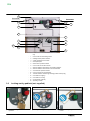
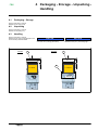
Secondary Distribution Switchgear FBX SF6 Gas-insulated switchboards CB function Instructions Installation - Commissioning Operating - Maintenance FBX Contents 1 Schneider Electric at your service . . . . . . . . . . . . . . . . . . . 1 1.1 1.2 1.3 1.4 1.5 Particular instructions for operations and interventions . . . . . . . . . . . . . . . . . . . Protection equipments . . . . . . . . . . . . . . . . . . . . . . . . . . . . . . . . . . . . . . . . . . . . . . Symbols of information . . . . . . . . . . . . . . . . . . . . . . . . . . . . . . . . . . . . . . . . . . . . . Symbols and important safety informations . . . . . . . . . . . . . . . . . . . . . . . . . . . . Contacts . . . . . . . . . . . . . . . . . . . . . . . . . . . . . . . . . . . . . . . . . . . . . . . . . . . . . . . . . 1 1 1 1 1 2 With regards to this User Manual . . . . . . . . . . . . . . . . . . . . 2 2.1 2.2 2.3 2.4 Reminder concerning normal service conditions (in accordance with the IEC62271-1 standard) . . . . . . . . . . . . . . . . . . . . . . . . . . . . . . . . . . . . . . . . . . . . . . * Permissible ambient temperature . . . . . . . . . . . . . . . . . . . . . . . . . . . . . . . . . . . * Installation altitude . . . . . . . . . . . . . . . . . . . . . . . . . . . . . . . . . . . . . . . . . . . . . . . . * Atmospheric pollution . . . . . . . . . . . . . . . . . . . . . . . . . . . . . . . . . . . . . . . . . . . . . * Permissible atmospheric humidity level . . . . . . . . . . . . . . . . . . . . . . . . . . . . . . Other technical notices to be consulted . . . . . . . . . . . . . . . . . . . . . . . . . . . . . . . . Tools (not supplied) required for the operations described in this user manual Tightening torque values [Nm] for standard assemblies (nut + bolt) . . . . . . . . . 2 2 2 2 2 2 2 3 3 Presentation of the 630 A CB Functional Unit . . . . . . . . . 4 3.1 3.2 Presentation of the CB Functional Unit's mimic diagram . . . . . . . . . . . . . . . . . . Locking-out by padlock (not supplied) . . . . . . . . . . . . . . . . . . . . . . . . . . . . . . . . . 4 5 4 Packaging - Storage - Unpacking - Handling . . . . . . . . . . 6 4.1 4.2 4.3 Packaging - Storage . . . . . . . . . . . . . . . . . . . . . . . . . . . . . . . . . . . . . . . . . . . . . . . Unpacking . . . . . . . . . . . . . . . . . . . . . . . . . . . . . . . . . . . . . . . . . . . . . . . . . . . . . . . . Handling . . . . . . . . . . . . . . . . . . . . . . . . . . . . . . . . . . . . . . . . . . . . . . . . . . . . . . . . . 6 6 6 5 Installation - Fixing - Connection of the HV cables . . . . 7 5.1 5.2 5.3 5.4 5.5 Installation and fixing to the floor . . . . . . . . . . . . . . . . . . . . . . . . . . . . . . . . . . . . . Earthing . . . . . . . . . . . . . . . . . . . . . . . . . . . . . . . . . . . . . . . . . . . . . . . . . . . . . . . . . . Cable connections . . . . . . . . . . . . . . . . . . . . . . . . . . . . . . . . . . . . . . . . . . . . . . . . . Fitting of a metering core on one or two cables per phase (optional) . . . . . . . . Example of cable connections with a single core per phase . . . . . . . . . . . . . . . 7 7 7 7 7 6 Mechanical interlocks . . . . . . . . . . . . . . . . . . . . . . . . . . . . . . . 9 6.1 6.2 Functional mechanical interlocks . . . . . . . . . . . . . . . . . . . . . . . . . . . . . . . . . . . . . ”Operating” interlocks by locks . . . . . . . . . . . . . . . . . . . . . . . . . . . . . . . . . . . . . . . Use of HV/LV/Transformer non-return interlocking on a CB function . . . . . . . . Representation of lock-type interlocks . . . . . . . . . . . . . . . . . . . . . . . . . . . . . . . . . Installation of lock-type interlocks . . . . . . . . . . . . . . . . . . . . . . . . . . . . . . . . . . . . 9 9 9 10 10 7 Use of the CB function . . . . . . . . . . . . . . . . . . . . . . . . . . . . . . 11 7.1 7.2 7.3 7.4 7.5 7.6 7.7 7.8 Operating accessories . . . . . . . . . . . . . . . . . . . . . . . . . . . . . . . . . . . . . . . . . . . . . Opening the earthing switch . . . . . . . . . . . . . . . . . . . . . . . . . . . . . . . . . . . . . . . . . Closing the earthing switch . . . . . . . . . . . . . . . . . . . . . . . . . . . . . . . . . . . . . . . . . . Closing the line isolating switch [earthing switch open - circuit breaker tripped] Opening the line isolating switch [circuit breaker tripped] . . . . . . . . . . . . . . . . . Closing the circuit breaker [Line Isolator closed] . . . . . . . . . . . . . . . . . . . . . . . . Re-arming the CB closing spring [CB closed] . . . . . . . . . . . . . . . . . . . . . . . . . . . Opening the circuit breaker [Line Isolator closed] . . . . . . . . . . . . . . . . . . . . . . . 11 11 11 12 12 13 13 14 8 CB Function diagram . . . . . . . . . . . . . . . . . . . . . . . . . . . . . . . 15 8.1 ”Metering - Protection - Signalling” section . . . . . . . . . . . . . . . . . . . . . . . . . . . . . 'Control' section . . . . . . . . . . . . . . . . . . . . . . . . . . . . . . . . . . . . . . . . . . . . . . . . . . . LV Fuse board (SCHURTER, 5x20) . . . . . . . . . . . . . . . . . . . . . . . . . . . . . . . . . . 15 16 16 9 WIC1 or DPX-1 protection relays (option) . . . . . . . . . . . . . 17 9.1 9.2 9.3 Configuring the protection relays . . . . . . . . . . . . . . . . . . . . . . . . . . . . . . . . . . . . . WIC1 & DPX-1 protection relays . . . . . . . . . . . . . . . . . . . . . . . . . . . . . . . . . . . . . WI1-SZ5 fault indicator . . . . . . . . . . . . . . . . . . . . . . . . . . . . . . . . . . . . . . . . . . . . . 17 17 17 10 Maintenance . . . . . . . . . . . . . . . . . . . . . . . . . . . . . . . . . . . . . . . 18 10.1 10.2 10.3 10.4 10.5 10.6 Levels of maintenance . . . . . . . . . . . . . . . . . . . . . . . . . . . . . . . . . . . . . . . . . . . . . General Safety Instructions . . . . . . . . . . . . . . . . . . . . . . . . . . . . . . . . . . . . . . . . . Maintenance of the mechanical control mechanism . . . . . . . . . . . . . . . . . . . . . . Corrective maintenance . . . . . . . . . . . . . . . . . . . . . . . . . . . . . . . . . . . . . . . . . . . . Removal of the protective cover for all maintenance operations . . . . . . . . . . . Location of LV components . . . . . . . . . . . . . . . . . . . . . . . . . . . . . . . . . . . . . . . . . . 18 18 18 18 19 19 8.2 AMTNoT170-02 revision: 06 i FBX 10.7 10.8 10.9 10.10 10.11 10.12 10.13 10.14 10.15 10.16 10.17 10.18 10.19 10.20 10.21 ii Replacement of the motor (1) [See § 10.6] . . . . . . . . . . . . . . . . . . . . . . . . . . . . . 20 Replacement of the motor fuse (10) [See Section 10.6] . . . . . . . . . . . . . . . . . . 21 Replacement of the closing coil (2) [See Section 10.6] . . . . . . . . . . . . . . . . . . . 21 Replacement of the tripping coil (3) [See Section 10.6] . . . . . . . . . . . . . . . . . . . 22 Replacement of a supplementary tripping coil release or undervoltage tripping coil (4) [See Section 10.6] . . . . . . . . . . . . . . . . . . . . . . . . . . . . . . . . . . . . . . . . . . . 23 Coil power . . . . . . . . . . . . . . . . . . . . . . . . . . . . . . . . . . . . . . . . . . . . . . . . . . . . . . . . 24 Replacement of the striker (5) [See section 10.6] . . . . . . . . . . . . . . . . . . . . . . . 24 Replacing the undervoltage coil control board (6) [See section 10.6] . . . . . . . 25 Replacing the diode bridge (7) [See section 10.6] . . . . . . . . . . . . . . . . . . . . . . . 25 Replacing the motor control board (8) [See Section 10.6] . . . . . . . . . . . . . . . . . 26 Replacing a motor re-arming contact (9) [mechanical control tripped and un-armed] [See section 10.6] . . . . . . . . . . . . . . . . . . . . . . . . . . . . . . . . . . . . . . . . . . . . . . . . . 27 Adjust the motor arming lock before this one of electrical arming contacts . . . 28 Replacement of an operation counter (11) [See section 10.6] . . . . . . . . . . . . . 29 For CB 2000 operatings . . . . . . . . . . . . . . . . . . . . . . . . . . . . . . . . . . . . . . . . . . . . 29 For CB 10000 operatings . . . . . . . . . . . . . . . . . . . . . . . . . . . . . . . . . . . . . . . . . . . 29 Mounting of an undervoltage tripping coil (4) [See section 10.6] . . . . . . . . . . . . 29 Mounting of an additional voltage release tripping coil (4) [See section 10.6] . 31 Mounting of an operation counter (11) [See section 10.6] . . . . . . . . . . . . . . . . . 32 For CB 2000 operatings . . . . . . . . . . . . . . . . . . . . . . . . . . . . . . . . . . . . . . . . . . . . 32 For CB 10000 operatings . . . . . . . . . . . . . . . . . . . . . . . . . . . . . . . . . . . . . . . . . . . 33 11 Politicy for Adaptation and Replacement of Schneider Electric . . . . . . . . . . . . . . . . . . . . . . . . . . . . . . . . . . . . . . . . . . . . 34 11.1 11.2 11.3 11.4 11.5 11.6 Definitions . . . . . . . . . . . . . . . . . . . . . . . . . . . . . . . . . . . . . . . . . . . . . . . . . . . . . . . . Different categories of spare parts [according to NF EN 13306 - NF X 60-319] Supply of spare parts . . . . . . . . . . . . . . . . . . . . . . . . . . . . . . . . . . . . . . . . . . . . . . Identification and storage of the parts . . . . . . . . . . . . . . . . . . . . . . . . . . . . . . . . . Presentation of the PAR . . . . . . . . . . . . . . . . . . . . . . . . . . . . . . . . . . . . . . . . . . . . Illustrated example of PAR . . . . . . . . . . . . . . . . . . . . . . . . . . . . . . . . . . . . . . . . . . Reuse or waste processing of replaced parts and packaging . . . . . . . . . . . . . . 34 34 34 34 34 35 35 12 Notes . . . . . . . . . . . . . . . . . . . . . . . . . . . . . . . . . . . . . . . . . . . . . . 36 AMTNoT170-02 revision: 06 FBX 1 Schneider Electric at your service © - Schneider Electric - 2010. Schneider Electric, the Schneider Electric logo and their figurative forms are Schneider Electric registered trademarks. The other brand names mentioned within this document, whether they be copyright or not, belong to their respective holders. Schneider Electric request the carefully reading of the following instructions in order to familiarize yourself with the product in this document before trying to install, operation, put into service or conduct the maintenance on it. Our products are fully quality controlled and tested at the factory in accordance with the standards and regulations currently in force. The correct functioning and lifespan of the product depend on respecting the installation, commissioning and exploitation instructions found in this manual. Not respecting these instructions is likely to invalidate any guarantee. Local safety requirements which are in accordance with these instructions, especially those regarding the safety of product operators and other site workers, must be observed. Schneider Electric declines any responsibility for the following points: - the non respect of the recommendations in this manual which make reference to the international regulations in force. - the non respect of the instructions by the suppliers of cables and connection accessories during installation and fitting operations, - possible aggressive climatic conditions (humidity, pollution, etc.) acting in the immediate environment of the materials that are neither suitably adapted nor protected for these effects. 1.1 Particular instructions for operations and interventions This user manual does not list the locking-out procedures that must be applied. The interventions described are carried out on de-energized equipment (in the course of being installed) or locked out (non operational). 1.2 1.3 A qualified person is one who has the skills and knowledge related to the construction, installation and operation of electrical equipment and has received safety training to recognize and avoid the hazards involved. Except when it is imposed, the wearing of the gloves has been voluntarily limited in this manual so as to have clear visuals of the hands and operations described. Symbols of information 06 Code for a product recommended and marketed by Schneider Electric 21 Nm Tightening torque value Example: 21 Nm 10 Mark corresponding to a key Symbols and important safety informations The following special messages may appear throughout this bulletin or on the equipment to warn of potential hazards or to call attention to information that clarifies or simplifies a procedure. DANGER DANGER indicates an imminently hazardous situation which, if not avoided, will result in death or serious injury. 1.5 All operations must be completed once started. The durations (for completing the operations mentioned) given in the maintenance tables are purely an indication and depend on on-site conditions. Protection equipments Only qualified and accredited people can operate on our products. They must be equipped with all the correct protective equipment required for the task being performed. 1.4 Whilst commissioning and operating the product all general safety instructions for electrical applications (protective gloves, insulating stool, etc.) must be respected, this in addition to the standard operating instructions. WARNING WARNING indicates a potentially hazardous situation which, if not avoided, can result in death or serious injury. NOTICE NOTICE is used to address practices not related to physical injury. The safety alert symbol shall not be used with this signal word. CAUTION CAUTION indicates a potentially hazardous situation which, if not avoided, can result in minor or moderate injury. Contacts Group Schneider Electric service centers are there for: J J J J J J Engineering and technical assistance Commissioning Training Preventive and corrective maintenance Spare parts Adaptation work Schneider Electric Energy France 35 rue Joseph Monier - CS 30323 F-92506 Rueil-Malmaison Cedex www.schneider-electric.com AMTNoT170-02 revision: 06 1 FBX 2.1 2 With regards to this User Manual Reminder concerning normal service conditions (in accordance with the IEC62271-1 standard) * Permissible ambient temperature The ambient air temperature should be comprised between - 5° C (on option -15 or -25°C) and + 40° C. The mean measured value for a 24 hour period must not exceed 35°C. * Installation altitude Items of HV equipment are defined in accordance with IEC Standards and can be used up to an altitude of 1000 m. Above this, you may have to take into account the reduced atmospheric pressure. For these specific cases, contact the Schneider Electric Sales Department * Atmospheric pollution The ambient air must not contain any dust particles, fumes or smoke, corrosive or flammable gases, vapours or salts. * Permissible atmospheric humidity level The average atmospheric relative humidity level measured over a 24-hour period must not exceed 95%. The average water vapour pressure over a period of 24 hours must not exceed 22 mbar. The average atmospheric relative humidity value measured over a period of one month must not exceed 90 %. The average water vapour pressure over a period of one month must not exceed 18 mbar. 2.2 Condensation may appear in case of any sharp variation in temperature, due to excessive ventilation, a high atmospheric humidity level or the presence of hot air. This condensation can be avoided by an appropriate lay-out of the room or of the building (suitably adapted ventilation, air driers, heating etc.). Whenever the humidity level is higher than 95 %, we recommend that you take appropriate corrective measures. For any assistance or advice, contact the Schneider Electric After-Sales department. Other technical notices to be consulted For all operations relating to the installation and use of the switchboard, see the manuals listed below. J J J J AMTNoT110-02 AMTNoT131-02 AMTNoT132-02 AMTNoT153-02 2.3 FBX FBX FBX FBX Guide to Civil Engineering Work Installation - Commissioning Operation - Maintenance Mechanical key-type interlocking Assembly - Operation Tools (not supplied) required for the operations described in this user manual - Crowbar - Scissors - Open-ended spanners sizes 8, 10 and 13 - 2 x open-ended spanners - size 7 - Allen key - sizes 2.5, 3, 4 and 5 mm - Box spanner - size 7 - Ratchet handle + extension with socket sizes 8, 10, 13 and 16 mm - Torque wrench - Cutting pliers 2 AMTNoT170-02 revision: 06 FBX 2.4 Tightening torque values [Nm] for standard assemblies (nut + bolt) Diameter Plastic (PA 6.6) Steel Class < 8.8 Steel Class > 8.8 < 10.9 Threaded fasteners with grease A2-70 M6 0.8 4.3 8.8 6.6 M8 1.8 10.5 21.0 15.8 M 10 3.5 14.0 42.0 35.0 M 12 6.0 - 70.0 60.0 M 16 12.0 - 170.0 134.0 AMTNoT170-02 revision: 06 3 FBX 3 Presentation of the 630 A CB Functional Unit This manual only covers the 630 A CB Function. It is complementary to the General Manual AMTNoT131 (See Section 2.2). 3.1 The 630 A CB Functional Unit is fitted with a C150 mechanical control mechanism. Presentation of the CB Functional Unit's mimic diagram 1 5 2 3 6 7 8 4 9 0 4 Key - 1 2 3 Lifting ring Function-Top Coupling Busbar connector - 4 5 6 Lower function coupling points Voltage presence indicator light and low voltage compartment panel Protective cover for the C150 mechanical control mechanism - 7 8 9 Access panel for the disconnecter switch mechanical control mechanism Interlocking by locks Cable compartment cover AMTNoT170-02 revision: 06 FBX 15 Extendable Extendable 12 13 10 9 11 8 7 1 5 2 6 14 3 4 0 3.2 J Key - 1 2 3 Lever socket for the earthing switch Earthing switch position indicator Cable compartment cover latch - 4 5 6 Descriptive plate Disconnector position indicator Lever socket for the disconnector - 7 8 9 Interlock between disconnector and earthing switches Interlock between disconnnector and circuit breaker Circuit breaker position indicator - 10 - 11 - 12 Lever socket for the circuit breaker “Primed-released” indicator light showing position of the spring Push button for tripping - 13 - 14 - 15 Push button for closing Fault indicator (optional) Operating counter Locking-out by padlock (not supplied) Locking-out using circuit-breaker operations. AMTNoT170-02 revision: 06 J Locking-out using the red trip button. J Locking-out using the green closure button. 5 FBX 4.1 4 Packaging - Storage - Unpacking Handling Packaging - Storage See the instructions in manual AMTNoT131-02 (See § 2.2). 4.2 Unpacking See the instructions in manual AMTNoT131-02 (See § 2.2). Handling See the instructions in manual AMTNoT137-02 (See § 2.2) displayed on the circuit-breaker protective blanket. 1st case NOTICE NOTICE When the CB unit is fitted with an LV cabinet on its roof, use a yoke (A) (see below). 2nd case A LV cabinet A 600 mm 100 mm 600 mm In the second case, attach a metal ring (B), diameter 25 mm (min.), to the lifting lugs. B LV cabinet 100 mm 4.3 900 mm 6 AMTNoT170-02 revision: 06 FBX 5 Installation - Fixing Connection of the HV cables 5.1 Installation and fixing to the floor Assemble the switchboard before fixing down to the floor. See the instructions in manual AMTNoT131-02 (See § 2.2). 5.2 Earthing See the instructions in manual AMTNoT131-02 (See § 2.2). 5.3 Cable connections For all connectivity operations, see the instructions in manual AMTNoT131-02 (See § 2.2). 5.4 J J The fitting of the core must be completed at the same time as the connections to the withdrawable plugs. The tightening of the fixings is completed after the plugs are connected. 5.5 J J Fitting of a metering core on one or two cables per phase (optional) J Phase L2: The core is fitted below the two others. J Installation of a core, with 2 cables per phase. Example of cable connections with a single core per phase Fit the rear crossmember core mounting (with rear cradle) to hold the central core in place. Screw in, but do not tighten, the 4 screws. AMTNoT170-02 revision: 06 J J J Pass the HVA cables through the opening in the cable run. Fit the cores onto the cables, making sure they are the right way round. Put together the plug-in connectors. J Phases L1 and L3: Lift the core to place it above the rear crossmember whilst attaching the socket to the crossmember. 7 FBX J Attach the front crossmember using 2 screws without tightening them. J Refit the front cradle for the Phase L2 core. J Phase L2: Lift the core to place it in the rear cradle whilst attaching the socket to the crossmember. Position the front crossmember. J Tighten the 2 screws on the front cradle. J Attach all cores (4 screws per unit). Attach the earthing wire using the front right hand side mounting screw. J J The three cores are shown in place. Attach the LV loom in two places along the centre of the front cross member. J Refit the protective cover. J J J J Remove the protective cover. Connect the secondary core circuits as per the identification marks and diagrams. J J Tighten all fixing bolts. Attach the cables using Rilsan cable ties. NOTICE Complete connection by clamping the cables (See the corresponding manual § 2.2). 8 AMTNoT170-02 revision: 06 FBX 6.1 6 Mechanical interlocks Functional mechanical interlocks The CB function is equipped with internal mechanical interlocks, called ”functional”, intended to avoid any kind of operating error. Circuit breaker Disconnector switch Earthing switch Access panel to the cable compartment 6.2 It is necessary to know these interlocks in order to operate the switchgear correctly. Position Circuit breaker Disconnector switch Earthing switch Access cover to cable compartment Closed - Locked (closed or open) Locked open Locked closed Open - Free Dependant on the position of the disconnector switch Dependant on the position of the earthing switch Closed Free - Locked open Locked closed Open Free (Normally Open) - Free Dependant on the position of the earthing switch Closed Free (Normally Open) Locked open - Free Open Free (Normally Open) Dependant on the position of the circuit breaker - Locked closed Open Free (Normally Open) Locked open Locked Closed - ”Operating” interlocks by locks Use of HV/LV/Transformer non-return interlocking on a CB function Commissioning J J J J J J J Earthing Switch is already locked ‘open’ with key 1. Recover Key 1. Go to the low voltage circuit breaker, introduce Key 1 into the CB lock and unlock it immediately. Plug in then close the LV circuit breaker. Return to the Functional Unit. Close the line isolator. Re-arm and trip the circuit breaker. De-energizing J J J J J J J J J J AMTNoT170-02 revision: 06 Trip the circuit breaker. Open the line isolator. Go to the LV switchboard, open and unplug the master circuit breaker. Lock this circuit breaker in its ‘withdrawn’ position using Key 1. Recover key 1 and go back to function CB. Introduce Key 1 into the earthing switch lock and unlock it immediately. Check that there is no voltage across the voltage indicator units. Close the earthing switch. Lock earthing switch using Key 2. Go to the transformer. 1st case, insulated transformer: - unlock transformer access (or plug-in termi nals) using Key 2. 2nd case, transformer with a double lock fitting: - unlock transformer access with key 2, - recover key 3 to unlock the plug-in terminals. 3rd case, transformer (with metal-clad enclo sure), > 2000kVA or with external plug-in termi nals: - introduce key 2 into the transfer lock, - recover key 3 to gain access to the trans former, - recover key 4 to gain access to the trans former or the plug-in terminals. 9 FBX Representation of lock-type interlocks Low Voltage 2 3 4 Function CB 3 1 3) Transformer (with enclosure) > 2000kVA × or or with external plug-in terminals 4 Low Voltage 3 1 ÉÉÉ ÉÉÉ ÉÉÉ ÉÉÉ 2) Transformer with a double lock fitted ⊂ 1 23 or 2 Low Voltage 2 ∩ 1 1) Insulated transformer or 1 GE Generator Unit Installation of lock-type interlocks See the instructions in manual AMTNoT153-02 (See § 2.2). 10 AMTNoT170-02 revision: 06 FBX 7 Use of the CB function 7.1 Operating accessories J Standard operating lever for the earthing switch (red end). 7.2 J J Standard operating lever for the load-break switch (black end). J Circuit breaker operating lever. J Lift the lever: the earthing switch is now in the open position. Remove the lever. Opening the earthing switch Check that the tag is fully lowered. Insert the appropriate lever (red end) into the earthing switch socket. 7.3 J J Grasp the lever with both hands. J Closing the earthing switch NOTICE Before closing the earthing switch, ensure there is no voltage across the indicator units (see corresponding manual - § 2.2). AMTNoT170-02 revision: 06 11 FBX J J Hold the locking tab open to the right. Insert the appropriate lever (red end) into the earthing switch socket. 7.4 J J J J 12 Grasp the lever with both hands. J J Pull the lever down: the earthing switch is closed. Remove the lever. Closing the line isolating switch [earthing switch open - circuit breaker tripped] Lift the locking tab. Insert the lever (black end) into the disconnector switch socket. 7.5 J J Grasp the lever with both hands. J J Lift the lever: The line isolator is now closed. Remove the lever. Opening the line isolating switch [circuit breaker tripped] Lift the locking tab. Insert the lever (black end) into the disconnector switch socket. J Grasp the lever with both hands. J J Pull the lever down: The line isolator is now open. Remove the lever. AMTNoT170-02 revision: 06 FBX 7.6 Closing the circuit breaker [Line Isolator closed] NOTICE Under normal operating conditions, CB manoeuvres are carried out with the line isolator closed. However, CB test manoeuvres are possible with the line isolator open. J J Circuit breaker open: make sure that the tag is fully lowered. Lift the tab and insert the lever into the re-arming spring's switch hub. J Turn the lever to the left to re-arm the CB closing spring (rotate through approx. 350°). CAUTION Do not force the lever at the end of the operating! J The indicator will show that the spring is 'armed'. 7.7 J J Press the (green) 'I' button. J J The circuit breaker is now closed. The CB closing spring is 'unarmed'. Re-arming the CB closing spring [CB closed] The closing spring is 'unarmed'. AMTNoT170-02 revision: 06 J For motorised controls, the CB closing spring is re-armed as soon as the CB is closed. J J For manual controls, you must manually re-arm the CB closing spring. Lift the tab and insert the lever into the re-arming spring's switch hub. 13 FBX J Turn the lever to the left to re-arm the CB closing spring (rotate through approx. 350°). 7.8 J 14 J The indicator will show that the spring is 'armed' even though the CB is closed. Opening the circuit breaker [Line Isolator closed] Press the (red) 'O' button. J The circuit breaker is now open. AMTNoT170-02 revision: 06 FBX 8 CB Function diagram Key Q01: Circuit breaker Q01-F11, Q01-F12: Tripping coils -YU: Undervoltage tripping coil Q01-F14: Closing coil Q01-F31: Striker pin Q01-LS1 to LS3: Spring position contacts Q01-S1: Circuit breaker position contact Q01-S52: Lever insertion locking contact Q01-S53, Q01-S54: Motor interlock contacts Q11: Disconnector Q11-S1: Disconnector position contact Q11-S51: Closing interlock contact 0 -H1: 'Pressure' indictor contact 0 0 0 -H301: 'Fault' indicator contact -K100: Anti-pumping board -K200: Electronic undervoltage trip unit 0 0 0 -K1: Instantaneous auxiliary relays -C1: Connector -F1: Fuse 0 0 0 -M: Motor V01, V02: Bridge rectifiers X1, X3: Test terminal box 0 0 X009, X108, X11, X12, X12A: Connectors X10, X14, X15, X16: Connectors Q81-S1: Earthing switch position contact Disconnector position contacts (option) Contacts for signalling pressure (option) Circuit breaker position contacts Armed/Unarmed position contact (option) ”Metering - Protection - Signalling” section Position Contacts for the earthing switch. 8.1 Contacts for signalling a fault (option) Protection Protection (Option - depending on type of relay) Metering (option) AMTNoT170-02 revision: 06 The terminals of 'current' circuits are highlighted and protected by a DANGER label. 15 FBX Optional Closing coil Tripping Coil 2nd tripping coil (option) Striker** (option) Optional Motorization Undervoltage tripping coil (option) 'Control' section Not simultaneously -K200 -K1 -YU -K100 Motorization board 8.2 LV Fuse board (SCHURTER, 5x20) Voltage Fuse calibre Reference (Schurter) 230VAC 800mA FST 0034.3116 220VDC 1A FST 0034.3117 1.6A FST 0034.3119 2A FST 0034.3120 60VDC 4A FST 0034.3123 48VDC 5A FST 0034.3124 24VDC 8A FST 0034.3126 125VAC 125VDC 110VAC 110VDC 16 Anti-pumping system AMTNoT170-02 revision: 06 FBX Configuring the protection relays NOTICE The relays are supplied pre-configured, with a default setting of their maximum levels. Orange ext. Reset White Green WIC1 & DPX-1 protection relays Red 9.2 NOTICE To adjust the protection relays, see the manual supplied with the switchboard. Black 9.1 9 WIC1 or DPX-1 protection relays (option) Purple Reset+ FI + Indicator J WIC1: Standard autonomous protection relay (without earthing fault). Optional: with earthing fault. 9.3 J Yellow Blue Reset Brown Brown FI − Reset− J DPX-1: Autonomous protection relay with earthing fault detection and indicator light: - flashing green: OK, - fixed green: problem with the relay, - fixed red: detection of fault current. J WI1-SZ5: Wiring connnectivity diagram. J Indicator showing a fault (red). J Press the green button to delete the fault. WI1-SZ5 fault indicator Indicator normal (no fault). AMTNoT170-02 revision: 06 17 FBX 10 Maintenance 10.1 Levels of maintenance Definition Levels Operations recommended in the instructions manual "installation - operation - maintenance", carried out by suitably qualified personnel having received training allowing them to intervene whilst respecting the safety rules. 1 Complex operations, requiring specific expertise and the implementation of support equipment in accordance with Schneider Electric's procedures. These are carried out by Schneider Electric or by a specialised technician, trained by Schneider Electric in the implementation of procedures, and who is equipped with specific equipment. 2 All preventive and corrective maintenance, all renovation and reconstruction work is carried out by Schneider Electric. 3 10.2 General Safety Instructions WARNING CAUTION WARNING Never separate the C150 control mechanism from the circuit breaker part. Never remove the command control cover without having cut off the LV auxiliaries. Ensure that the springs have been released by carrying out a complete O-C-O cycle. 10.3 Maintenance of the mechanical control mechanism Under normal installation and service conditions, the CB630 circuit breaker requires no maintenance: - throughout the 25 years of its service life, - as long as it has not reached the maximum number of operating cycles. NOTICE By cycle we mean a closing then an opening operation. WARNING The internal electrical connections as well as the adjustments to the control mechanism are carried out at the factory and cannot be modified. PREVENTIVE MAINTENANCE Frequency Recommended operations Levels 3 years 1 2 3 Inspection of the tightening of the threaded fasteners and presence of stop elements X - X X Carry out a few opening and closing operations of the circuit breaker with the manual (and electrical) controls to ensure its correct operation. X - X X Monitor the general appearance of the mechanical components and connections X - X X 10.4 Corrective maintenance CORRECTIVE MAINTENANCE Replacements or modifications Levels See chapter 1 2 3 Replacement of the motor (1) 10.7 - X X Replacement of the motor fuse (10) 10.8 X X X Replacement of the closing coil (2) 10.9 - X X Replacement of the tripping coil (3) 10.10 - X X Replacement of an under/overvoltage tripping coil (4) 10.11 - X X Replacement of the striker (5) 10.13 - X X Replacement of the control card of the undervoltage tripping coil (6) 10.14 - X X Replacement of a diode bridge (7) 10.15 X X X Replacing the motor electronic control card (8) 10.16 - X X Replacement of a motor reset contact (9) 10.17 - X X Replacement of the operation counter (11) 10.18 X X X See chapter 1 2 3 Mounting of an undervoltage tripping coil (4) Adaptation of additional functions 10.19 - X X Mounting of an additional voltage release tripping coil (4) 10.20 - X X Mounting of an operation counter (11) 10.21 - X X 18 AMTNoT170-02 revision: 06 FBX 10.5 Removal of the protective cover for all maintenance operations NOTICE NOTICE Maintenance operations absolutely must be carried out with the circuit breaker open and the control mechanism deactivated. NOTICE Cut off the LV auxiliaries’ power circuits. Complete replacement of a C150 control mechanism can only be carried out by Schneider Electric. J Unscrew the 5 attachment screws holding the front plates (Allen key for hexagonal screws size 4). J Remove the plate. J Unscrew the 4 cover fixing screws (Allen key for hexagonal screws size 4). J Remove the complete cover and twin front cover assembly. J Unscrew the 4 cover mount fixing screws (Allen key for hexagonal screws size 4). J Pull off the cover mounts. 10.6 Location of LV components 2 11 8 0 3 4 5 1 2 3 Motor Closing Coil Tripping Coil on voltage release 7 6 1 - 4 5 Supplementary tripping coil on voltage release or undervoltage tripping coil Striker - 6 7 Electronic control card for voltage release coil Diode bridge - 8 9 10 Electronic motor board Motor rearming contacts Motor fuses - 11 Operating counter (missing on this picture) 9 10 J Key - Location of LV elements. AMTNoT170-02 revision: 06 19 FBX 10.7 Replacement of the motor (1) [See § 10.6] Apply the General Safety Instructions for Electrical Applications and the particular rules for the network concerned for locking out procedures. Tools required: - Cutting pliers - Allen keys for hexagonal screws size 5 + extension and ratchet wrench Parts required: - 1 motor of the same reference - 3 washers + 3 mounting bolts - 3 Rilsan cable ties Duration: 1 h 30 Disconnect the LV cables from the motor. The motor is kept in place by its 3 fixing points. J Unscrew each of the the fixing screws (Allen key for hexagonal screws size 5). J Remove and extract the motor. J J Supply kit also containing this notice. J Present the new motor. Identify the drive pin. J Using the lever, turn the mechanism's shaft clockwise to align the slot with the pin. Make sure that the three mounting points are flat against the partition panel. Tighten the fixing bolts. J Reconnect the motor wires. Re-clamp the cables. J J 1 J J 20 Engage the motor with its centring device (1) and use the 3 bolts and 3 new washers supplied. Insert the operating lever to align the centring device and motor drive shaft. J J J AMTNoT170-02 revision: 06 FBX 10.8 Replacement of the motor fuse (10) [See Section 10.6] Apply the General Safety Instructions for Electrical Applications and the particular rules for the network concerned for locking out procedures. J The motor fuse is located in the black fuse holder. Tools required: - Allen key for hexagonal screw size 3 - Flat headed screwdriver Parts required: - 1 fuse with the same reference Duration: 0 h 30 J J Open the fuse holder. Replace the fuse then close the holder. J Voltage Fuse 24 VDC 8A 48 VDC 5A 60 VDC 4A 110 VDC / 110 VAC 2A 125 VDC / 125 VAC 1,6 A 220 VDC 1A 230 VAC 0,8 A Tables of correspondence between SCHURTER type fuses (20x5) 10.9 Replacement of the closing coil (2) [See Section 10.6] Apply the General Safety Instructions for Electrical Applications and the particular rules for the network concerned for locking out procedures. J J Hold the coil in place. Unscrew and remove the 2 fixing bolts (Allen key of 3 mm). AMTNoT170-02 revision: 06 Tools required: - Cutting pliers - Allen key for hexagonal screw size 3 - 2 x open-ended spanners - size 7 J J Cut the fixing collars on the wiring. Disconnect the connector from the coil. Parts required: - 1 coil with the same reference - 2 pre-treated bolts and 2 washers - 3 Rilsan cable ties Duration: 1 h J Extract the coil from the front. 21 FBX J Supply kit also containing this notice. J J Positioning the new coil. Insert and tighten the 2 new mounting bolts supplied. J J Reconnect the LV connector. Fix the cables in place using Rislan cable ties. 10.10 Replacement of the tripping coil (3) [See Section 10.6] Apply the General Safety Instructions for Electrical Applications and the particular rules for the network concerned for locking out procedures. Tools required: - Cutting pliers - Allen key for hexagonal screw size 3 & 4 - 2 x open-ended spanners - size 7 Parts required: - 1 coil with the same reference - 2 pre-treated bolts + 2 plate washers + 2 grower washers - 3 Rilsan cable ties Duration: 1 h 30 NOTICE If an additional voltage release or undervoltage tripping coil is present, it will be necessary to dismount it and remount it after the fuse is replaced. See instructions in section 10.11. J J Unscrew the two fixing screws on the LV compartment display panel (Allen key size 4). Unclip the panel and place it on the top of the FBX panel. J J J J 22 Note which way round the coil goes. Remove this coil from the right hand side. J Cut the fixing collars on the wiring. Disconnect the connector from the coil. J Supply kit for a voltage release coil also containing this notice. J J J Hold the coil in place. Unscrew and remove the 2 fixing bolts (Allen key of 3 mm). Positioning the new coil. Insert and tighten the 2 new mounting bolts supplied. AMTNoT170-02 revision: 06 FBX 10.11 Replacement of a supplementary tripping coil release or undervoltage tripping coil (4) [See Section 10.6] Apply the General Safety Instructions for Electrical Applications and the particular rules for the network concerned for locking out procedures. Tools required: - Cutting pliers - Allen key for hexagonal screw size 3 - 2 x open-ended spanners - size 7 Parts required: - 1 coil with the same reference - 2 pre-treated bolts and 2 washers - 3 Rilsan cable ties Duration: 1 h NOTICE Coil (4) may be either on voltage release or undervoltage/application. J J J J Cut the fixing collars on the wiring. Disconnect the connector from the coil. For an undervoltage trip coil, remove the coil board (see § 10.14). J Supply kit for a voltage release coil also containing this notice. J AMTNoT170-02 revision: 06 J Hold the coil in place. Unscrew and remove the 2 fixing bolts (Allen key of 3 mm). J Supply kit for an undervoltage coil also containing this notice. J J J Note which way round the coil goes. Remove this coil from the right hand side. Positioning the new coil. Insert and tighten the 2 new mounting bolts supplied. 23 FBX J For an undervoltage coil, install the new board (See § 10.14). J J Reconnect the LV connector. Fix the cables in place using Rislan cable ties. 10.12 Coil power Undervoltage coil Voltage Voltage release coil Inrush power Holding power Inrush power 24 VDC 240 W 4.6 W 960 W 48 VDC 256 W 4.7 W 470 W 60 VDC 248 W 7.0 W 450 W 110 VDC 172 W 4.0 W 620 W 125 VDC 166 W 4.2 W 521 W 220 VDC 193 W 3.5 W 386 W 120 VAC 164 W 4.5 W 521 W 230 VAC 266 W 4.1 W 386 W 10.13 Replacement of the striker (5) [See section 10.6] Apply the General Safety Instructions for Electrical Applications and the particular rules for the network concerned for locking out procedures. Tools required: - Cutting pliers - Allen key for hexagonals screw size 3 - 2 x open-ended spanners - size 8 Parts required: - 1 striker pin with the same reference - 2 pre-treated bolts and 2 washers - 3 Rilsan cable ties Duration: 1 h NOTICE To change the striker (5), first remove the trip coil (4) (See section 10.11). J Cut the fixing collars on the wiring. J Disconnect the connector from the striker. J Hold the striker in place. Unscrew and remove the 2 fixing bolts (Allen key of 3 mm). J 24 J Remove the striker from the front. J Supply kit also containing this notice. AMTNoT170-02 revision: 06 FBX J Position the new striker so that it presses against the screw head: the pin is in the centre of the light. J Insert and tighten the 2 new mounting bolts supplied. J J Reconnect the LV connector. Fix the cables in place using Rislan cable ties. 10.14 Replacing the undervoltage coil control board (6) [See section 10.6] Apply the General Safety Instructions for Electrical Applications and the particular rules for the network concerned for locking out procedures. J Using a flat headed screwdriver, loosen the two connectors. Tools required: - Flat headed screwdriver - 8 mm spanner Parts required: - 1 board of the same reference Duration: 0 h 30 J Unscrew the 2 fixing screws (8 mm spanner). J J Pull out the board. Attach and reconnect the new board in its place. 10.15 Replacing the diode bridge (7) [See section 10.6] Apply the General Safety Instructions for Electrical Applications and the particular rules for the network concerned for locking out procedures. AMTNoT170-02 revision: 06 Tools required: - Allen key for hexagonal screw size 3 - Flat headed screwdriver Parts required: - 1 diode bridge of the same reference Duration: 0 h 30 25 FBX J J J Unscrew the central bolt holding the bridge in place. Replace the diode bridge Refit the new bridge in its place. 10.16 Replacing the motor control board (8) [See Section 10.6] Apply the General Safety Instructions for Electrical Applications and the particular rules for the network concerned for locking out procedures. J J 26 The motor control board is lodged against the left hand upright in the C150 control compartment. Press the two pins on the front to free the board. Tools required: - Allen key for hexagonal screw size 3 - Flat headed screwdriver Parts required: - 1 board of the same reference Duration: 1 h 00 J J Lightly push the board aside then pull forwards to free from its rear connector. Pull out the board from the bottom. J J J Disconnect the board. Replace the board with one of the same reference. Repeat the operations detailed above in reverse to refit the new board. AMTNoT170-02 revision: 06 FBX 10.17 Replacing a motor re-arming contact (9) [mechanical control tripped and un-armed] [See section 10.6] J The motor re-arming contacts are located in the bottom right hand corner of the C150, behind the front panel. J Remove the motor according to the instructions in § 10.7 to enable easy access to the upper spring fastening. J By inside, unlock the lock nut of the left screw (box spanner 7). Loosen then remove the two mounting bolts from the front (Allen key for hexagonal screw size 2.5). Unhook the return spring. Mark and disconnect the LV wires. Unscrew the two lever contact support screws to enable easy access to the upper spring fastening. J Supply kit for rearm contact J J Remove the old spring. Hook the new spring in place. Bring the new support and its contacts close to the spring. Using a wire, hook the other spring coil into the support hole. J J Reconnect the wires. J J CAUTION The screw on the left has a lock nut. J J J AMTNoT170-02 revision: 06 J Fix the support in place with two new screws but do not tighten them fully. 27 FBX J J Refit the lever safety contact and fix it in place using 2 screws. Refit the motor and fix it in place according to the instructions in § 10.7. Adjust the motor arming lock before this one of electrical arming contacts J Loosen the 2 screws on the end of the lock slightly. J Turn this lock to align the arrow horizontally in the window. J Once this adjustment has been made, tighten the 2 screws (Allen key for hexagonal screw size 2.5). J Turn the mount to bring the contact tabs into contact with the lock. J View of the inside of the mechanism: The tabs are pressing against the lock probe. J Tighten the 2 fixing screws (Allen key for hexagonal screw size 2.5). By inside, tighten the lock nut of the left screw (box spanner 7). J 28 AMTNoT170-02 revision: 06 FBX 10.18 Replacement of an operation counter (11) [See section 10.6] Apply the General Safety Instructions for Electrical Applications and the particular rules for the network concerned for locking out procedures. Tools required: - Allen key for hexagonal screw size 3 - Flat headed screwdriver Parts required: - 1 Operation counter with its lever Duration: 1 h 00 For CB 2000 operatings Lever Spring blade J J The operation counter is held in place on its support by 2 screws. Loosen and remove these 2 screws. J Fit the new counter: the lever should be positioned above the spring blade. J J Insert and tighten the 2 fixing screws. The operation counter is operational starting at the number indicated: it cannot be reset to zero. For CB 10000 operatings Lever Spring J J The operation counter is held in place on its support by 2 screws. Loosen and remove these 2 screws. J J J Unclamp the spring attached to the lever. Extract the counter. Attach the spring to the new counter's lever. J J Insert and tighten the 2 fixing screws. The operation counter is operational starting at the number indicated: it cannot be reset to zero. 10.19 Mounting of an undervoltage tripping coil (4) [See section 10.6] Apply the General Safety Instructions for Electrical Applications and the particular rules for the network concerned for locking out procedures. AMTNoT170-02 revision: 06 Tools required: - Cutting pliers - Ratchet wrench + extension + size 5 Allen key socket - Allen key for hexagonal screw size 3 Parts required: - 1 adaptation kit for undervoltage tripping coil (see below) Duration: 1 h 30 29 FBX J Adaptation kit for an undervoltage coil also containing this notice. J Free housing for installation of coil. J Insert the coil from the right, the rounded striker in the front. J Hold the coil in place. Insert the two screws and two washers. Tighten the two screws (size 3 Allen key). J Install the coil board. Screw and tighten the 2 nuts. J Connect the wires of the new coil. Connect the wiring cables connector to the coil board. J Position the wiring cables and lift it into the LV compartment. Attach the wiring cables at 3 points using the cable ties. J Loosen and push the end stop at the far right of the lower rail to the right. Position the 2 terminals of the wiring cables in the space made available. Tighten then block the end stop in place. J J J J J J J CAUTION It is now mandatory to energize this coil to trip the circuit breaker. 30 AMTNoT170-02 revision: 06 FBX 10.20 Mounting of an additional voltage release tripping coil (4) [See section 10.6] Apply the General Safety Instructions for Electrical Applications and the particular rules for the network concerned for locking out procedures. Tools required: - Cutting pliers - Allen key for hexagonal screw size 3 - 2 x open-ended spanners - size 7 Parts required: - 1 Adaptation kit for additional coil (see below) Duration: 1 h 00 J Adaptation kit for a voltage release coil also containing this notice. J Free housing alongside the first trip coil to install the second coil. J Hold the coil in place. Insert the two screws and two washers. Tighten the two screws (size 3 Allen key). J Connect the connector to the corresponding wiring cables. Clamp the cables in place using the cable ties. J J AMTNoT170-02 revision: 06 J J Insert the coil from the right, the protruding part of the hub facing the rear. 31 FBX 10.21 Mounting of an operation counter (11) [See section 10.6] Apply the General Safety Instructions for Electrical Applications and the particular rules for the network concerned for locking out procedures. Tools required: - Allen key for hexagonal screw size 3 - Pipe wrench size 5.5 - 1 hammer - 1 copper drift pin Parts required: - 1 adaptation kit for operation counter (See below). Duration: 1 h 00 For CB 2000 operatings Lever Spring blade Side view J Adaptation kit for an operation counter also containing this notice. J J J Fix the counter support to the vertical plate using the 2 screws and 2 nuts supplied. J Position the spring blade on the drive bearing. Fix the spring blade in place using the 2 small screws and 2 nuts. Note: the nut is placed on the outside. J Fit the counter: the lever should be positioned above the spring blade. The operation counter is operational starting at the number indicated: it cannot be reset to zero. J On the front plate, knock out the plug facing the counter (hammer + copper drift pin). Clip the small round porthole onto this housing. J 32 AMTNoT170-02 revision: 06 FBX For CB 10000 operatings Lever Spring J Adaptation kit for an operation counter also containing this notice. J Insert the bottom of the spring into the hole on the drive bearing. J Insert the top of the spring into the hole on the counter lever. J Fix the counter support to the vertical plate using the 2 screws and 2 washers supplied. J The operation counter is operational starting at the number indicated: it cannot be reset to zero. J On the front plate, knock out the plug facing the counter (hammer + copper drift pin). Clip the small round porthole onto this housing. J AMTNoT170-02 revision: 06 33 FBX 11 Politicy for Adaptation and Replacement of Schneider Electric 11.1 Definitions Spare part is a part that is designed to replace an existing one with a view to re-establishing or maintaining the original function. PAR (Policy for Adaptation and Replacement) is a technical manual which setting out in detail the Schneider Electric policy for the supply and replacement of spare parts for the purposes of maintenance, adaptation or renovation. FAR is a technical notice or leaflet setting out the spare part replacement procedure for the purposes of maintenance, adaptation or renovation. 11.2 Different categories of spare parts [according to NF EN 13306 - NF X 60-319] Consumable Use Wearing parts, designed to be replaced after a predeter mined number of uses. Spare part Part designed for unscheduled replacement but with a lifetime that may be reduced through particular condi tions of use. Maintenance stock, required to ensure optimum maintenance operations for 6 years. Use Safety stock of spare parts replaced during corrective maintenance. Spare part for exceptional purposes Use Spare part that is normally not necessary during the lifetime of a product. Safety stock of spare parts or sub-assemblies replaced during urgent corrective maintenance. 11.3 Supply of spare parts Individual supply Use Spare part ordered occasionally by the customer. Specific need due to an accident or the destruction of the original part. Supplied on commissioning Use All parts supplied at time of commissioning Preventive stock of spare parts replaced during installation of panel. Supplied on Short list Use All parts supplied for first maintenance procedure. Maintenance stock, required to ensure optimum maintenance operations for 6 years. Supplied on List Use All parts or sub-assemblies stocked on customer site. Safety stock of spare parts or sub-assemblies replaced during urgent corrective maintenance. 11.4 Identification and storage of the parts NOTICE For all orders for spare parts, it is necessary to enclose the equipment characteristics form. The components should be stored away from dust, humidity and the sun. In order to facilitate their retrieval, they must be marked by the Schneider Electric reference number. Certain components are fragile, they should preferably be stored in their original factory packaging. 11.5 Presentation of the PAR Intervention What for? Where? Replacement Standard exchange or part replacement Customer site Adaptation Modification or installation of sub-assembly in kit format Customer site Modification Modification, transformation or improvement often in an upgrade cycle Customer site Renovation Technological upgrade requiring suitable knowledge and tools Schneider Electric site 34 AMTNoT170-02 revision: 06 FBX Illustrated example of PAR - Equipment range - Year of manufacture - Purchase order number: IDENTIFICATION Replacement Adaptation Replacement: - Scheduled - Unscheduled - Exceptional Characteristics: - Voltage - Quantity Modification PART/ASSEMBLY Renovation - List of parts - Manual (FAR) KIT Unitary: - Individual or Grouped: - Commissioning - Short List - List Kit adaptation Type of supply STORAGE INSTALLATION END OF LIFE PROCESSING Specific to After-Sales Department: Characteristics: - Voltage - Quantity - Duration - Conditions Levels: Site: - 1 Customer - Customer site - 2 Trained customer - Schneider Electric site - 3 Schneider Electric - Packaging - Replaced spare part 11.6 Reuse or waste processing of replaced parts and packaging NOTICE Waste parts, sub-assemblies and packaging are to be removed through approved waste collection and processing channels. AMTNoT170-02 revision: 06 35 FBX 12 Notes If you have any comments on the use of this document or on the use of the equipment and services that are described in it, please send us your remarks, suggestions and wishes to: Schneider Electric Service Technique BP 84019 F-71040 Mâcon Cedex 9 - FRANCE Fax: 33 (0)3 85 29 36 36 36 AMTNoT170-02 revision: 06 E 2010 Schneider Electric - All rights reserved Schneider Electric Energy France 35, rue Joseph Monier CS 30323 F - 92506 Rueil-Malmaison Cedex RCS Nanterre 511 746 356 Capital social 6 909 620 € www.schneider-electric.com Due to possible changes in standards and equipment, the characteristics and images shown in this document can only be confirmed by contacting our departments. Publication: Schneider Electric Design: Schneider Electric 11-2010 AMTNoT170-02 revision: 06