1
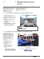
Secondary Distribution Switchgear
FBX
SF6 Gas-insulated switchboards
Instructions
Operation - Maintenance
FBX
AMTNoT132-02 revision: 04
Contents
1
Schneider Electric at your service . . . . . . . . . . . . . . . . . . .
1
1.1
1.2
Our Service Unit: our specialists, and suitably adapted services... . . . . . . . . .
Schneider Electric Training: Together, let us develop our skills... . . . . . . . . . . .
1
1
2
With regards to this User Manual . . . . . . . . . . . . . . . . . . . .
2
2.1
2.2
2
2.3
2.4
2.5
Responsibilities . . . . . . . . . . . . . . . . . . . . . . . . . . . . . . . . . . . . . . . . . . . . . . . . . . .
Particular instructions for operations and interventions on energized
equipment . . . . . . . . . . . . . . . . . . . . . . . . . . . . . . . . . . . . . . . . . . . . . . . . . . . . . . . .
Other technical notices to be consulted . . . . . . . . . . . . . . . . . . . . . . . . . . . . . . . .
Tools (not supplied) required for the operations described in this user manual
Symbols & conventions . . . . . . . . . . . . . . . . . . . . . . . . . . . . . . . . . . . . . . . . . . . . .
2
2
2
2
3
Functional interlocks . . . . . . . . . . . . . . . . . . . . . . . . . . . . . . .
3
3.1
3.2
3.3
3.4
Functional mechanical interlocks . . . . . . . . . . . . . . . . . . . . . . . . . . . . . . . . . . . . .
Interlocks for functions C and T1 . . . . . . . . . . . . . . . . . . . . . . . . . . . . . . . . . . . . .
Interlocks for function T2 . . . . . . . . . . . . . . . . . . . . . . . . . . . . . . . . . . . . . . . . . . . .
Interlocks for function Sb . . . . . . . . . . . . . . . . . . . . . . . . . . . . . . . . . . . . . . . . . . .
3
3
3
3
4
Operating accessories . . . . . . . . . . . . . . . . . . . . . . . . . . . . . .
4
4.1
4.2
4.3
Reminder for Manual Operations . . . . . . . . . . . . . . . . . . . . . . . . . . . . . . . . . . . . .
Operating accessories . . . . . . . . . . . . . . . . . . . . . . . . . . . . . . . . . . . . . . . . . . . . .
Lockouts using padlocks (Optional) . . . . . . . . . . . . . . . . . . . . . . . . . . . . . . . . . . .
4
4
4
5
Use of the RE function . . . . . . . . . . . . . . . . . . . . . . . . . . . . . .
5
5.1
5.2
Opening the earthing switch . . . . . . . . . . . . . . . . . . . . . . . . . . . . . . . . . . . . . . . . .
Closing the earthing switch . . . . . . . . . . . . . . . . . . . . . . . . . . . . . . . . . . . . . . . . . .
5
5
6
Use of the C function . . . . . . . . . . . . . . . . . . . . . . . . . . . . . . .
6
6.1
6.2
6.3
6.4
6.5
Opening the earthing switch . . . . . . . . . . . . . . . . . . . . . . . . . . . . . . . . . . . . . . . . .
Closing the earthing switch . . . . . . . . . . . . . . . . . . . . . . . . . . . . . . . . . . . . . . . . . .
Closing the load break switch . . . . . . . . . . . . . . . . . . . . . . . . . . . . . . . . . . . . . . . .
Opening the load break switch . . . . . . . . . . . . . . . . . . . . . . . . . . . . . . . . . . . . . . .
Movements of motorised control mechanisms . . . . . . . . . . . . . . . . . . . . . . . . . .
6
6
7
7
7
7
Use of the T1 function . . . . . . . . . . . . . . . . . . . . . . . . . . . . . .
8
7.1
7.2
7.3
7.4
7.5
Opening the earthing switch . . . . . . . . . . . . . . . . . . . . . . . . . . . . . . . . . . . . . . . . .
Closing the earthing switch . . . . . . . . . . . . . . . . . . . . . . . . . . . . . . . . . . . . . . . . . .
Closing the load break switch . . . . . . . . . . . . . . . . . . . . . . . . . . . . . . . . . . . . . . . .
Manually opening the load break switch . . . . . . . . . . . . . . . . . . . . . . . . . . . . . . .
Movements of motorised control mechanisms . . . . . . . . . . . . . . . . . . . . . . . . . .
8
8
8
8
8
8
Use of the T2 function . . . . . . . . . . . . . . . . . . . . . . . . . . . . . .
9
8.1
8.2
8.3
8.4
8.5
8.6
8.7
8.8
Opening the earthing switch . . . . . . . . . . . . . . . . . . . . . . . . . . . . . . . . . . . . . . . . .
Closing the earthing switch . . . . . . . . . . . . . . . . . . . . . . . . . . . . . . . . . . . . . . . . . .
Closing the line isolating switch [circuit breaker open] . . . . . . . . . . . . . . . . . . . .
Opening the line isolating switch [circuit breaker open] . . . . . . . . . . . . . . . . . . .
Closing the circuit breaker [Line Isolator closed] . . . . . . . . . . . . . . . . . . . . . . . .
Opening the circuit breaker [Line Isolator closed] . . . . . . . . . . . . . . . . . . . . . . .
Closing the circuit breaker [Line Isolator open] . . . . . . . . . . . . . . . . . . . . . . . . . .
Movements of motorised control mechanisms . . . . . . . . . . . . . . . . . . . . . . . . . .
9
9
9
9
10
10
10
10
9
Use of Function Sb . . . . . . . . . . . . . . . . . . . . . . . . . . . . . . . . .
11
9.1
9.2
9.3
9.4
9.5
Opening the earthing switch . . . . . . . . . . . . . . . . . . . . . . . . . . . . . . . . . . . . . . . . .
Closing the earthing switch . . . . . . . . . . . . . . . . . . . . . . . . . . . . . . . . . . . . . . . . . .
Closing the load break switch . . . . . . . . . . . . . . . . . . . . . . . . . . . . . . . . . . . . . . . .
Opening the load break switch . . . . . . . . . . . . . . . . . . . . . . . . . . . . . . . . . . . . . . .
Movements of motorised control mechanisms . . . . . . . . . . . . . . . . . . . . . . . . . .
11
11
11
11
11
10
Using motorised functions . . . . . . . . . . . . . . . . . . . . . . . . . .
12
10.1
10.2
10.3
10.4
10.5
10.6
Movements of motorised control mechanisms [Optional] . . . . . . . . . . . . . . . . .
Manual emergency movements of motorised controls . . . . . . . . . . . . . . . . . . . .
Approximate number of turns for backup manual control levers . . . . . . . . . . . .
Manual interventions involving Functions C and Sb [Earthing switch open] . .
Manual interventions involving Function T1 [Earthing switch open] . . . . . . . . .
Manual interventions involving Function T2 [Earthing switch open] . . . . . . . . .
12
12
12
12
13
13
11
Maintenance . . . . . . . . . . . . . . . . . . . . . . . . . . . . . . . . . . . . . . .
14
11.1
11.2
Levels of maintenance . . . . . . . . . . . . . . . . . . . . . . . . . . . . . . . . . . . . . . . . . . . . .
Preventive maintenance . . . . . . . . . . . . . . . . . . . . . . . . . . . . . . . . . . . . . . . . . . . .
14
14
i
FBX
11.3
11.4
11.5
11.6
Corrective maintenance . . . . . . . . . . . . . . . . . . . . . . . . . . . . . . . . . . . . . . . . . . . .
Replacement of the three fuses . . . . . . . . . . . . . . . . . . . . . . . . . . . . . . . . . . . . . .
Replacement of a fuse . . . . . . . . . . . . . . . . . . . . . . . . . . . . . . . . . . . . . . . . . . . . .
When using under 12 kV . . . . . . . . . . . . . . . . . . . . . . . . . . . . . . . . . . . . . . . . . . . .
Replacement of a voltage indicator unit [E.g.: Type VPIS] . . . . . . . . . . . . . . . .
Periodic frequency for maintenance operations of the VDS boxes . . . . . . . . .
14
14
14
16
16
17
12
Spare parts . . . . . . . . . . . . . . . . . . . . . . . . . . . . . . . . . . . . . . . .
18
12.1
12.2
12.3
The spare part . . . . . . . . . . . . . . . . . . . . . . . . . . . . . . . . . . . . . . . . . . . . . . . . . . . .
Identification of materials . . . . . . . . . . . . . . . . . . . . . . . . . . . . . . . . . . . . . . . . . . . .
Storage conditions . . . . . . . . . . . . . . . . . . . . . . . . . . . . . . . . . . . . . . . . . . . . . . . . .
18
18
18
13
Cable testing . . . . . . . . . . . . . . . . . . . . . . . . . . . . . . . . . . . . . . .
19
13.1
13.2
13.3
Preparation of the function . . . . . . . . . . . . . . . . . . . . . . . . . . . . . . . . . . . . . . . . . .
Cable testing with plug-in `T' piece connectors (busbar energised) . . . . . . . . .
Cable tests: EON specification with plug-in 'T' piece connectors
[busbar energised] . . . . . . . . . . . . . . . . . . . . . . . . . . . . . . . . . . . . . . . . . . . . . . . . .
Testing the casing of plug-in connectors . . . . . . . . . . . . . . . . . . . . . . . . . . . . . . .
19
19
14
Characteristics and Volumes of SF6 gas . . . . . . . . . . . . .
21
14.1
14.2
14.3
14.4
General characteristics . . . . . . . . . . . . . . . . . . . . . . . . . . . . . . . . . . . . . . . . . . . . .
Filling pressure . . . . . . . . . . . . . . . . . . . . . . . . . . . . . . . . . . . . . . . . . . . . . . . . . . . .
Operating thresholds of the pressure gauge contacts . . . . . . . . . . . . . . . . . . . .
FBX functions . . . . . . . . . . . . . . . . . . . . . . . . . . . . . . . . . . . . . . . . . . . . . . . . . . . . .
21
21
21
21
15
At the end of the equipment's operational life . . . . . . . .
22
15.1
15.2
15.3
15.4
Valorization of the equipment . . . . . . . . . . . . . . . . . . . . . . . . . . . . . . . . . . . . . . . .
Safety instructions . . . . . . . . . . . . . . . . . . . . . . . . . . . . . . . . . . . . . . . . . . . . . . . . .
Dismantling of the equipment service . . . . . . . . . . . . . . . . . . . . . . . . . . . . . . . . .
Distribution and valorization of the materials used for FBX (See § 15.1) . . . . .
22
22
22
23
16
Notes . . . . . . . . . . . . . . . . . . . . . . . . . . . . . . . . . . . . . . . . . . . . . .
24
13.4
ii
20
20
AMTNoT132-02 revision: 04
FBX
1 Schneider Electric at your
service
Operations and maintenance may only be
carried out by personnel who have received
suitable authorisation for the operations and
manœuvres they are responsible for
performing.
If this is not the case, please refer to our
Service Unit or Training Centre.
1.1
All locking-out operations must be performed
according to the ”General Safety Instructions
booklet for Electrical Applications”
UTE C 18 510 (or its equivalent outside
FRANCE).
Our Service Unit: our specialists, and suitably adapted services...
Guarantee extension contracts in relation to
the selling of new equipment,
Supervision of HVA switchgear installations,
Technical advice, diagnoses of the facilities,
expertise,
Maintenance contracts adapted to operational
constraints,
Systematic or conditional preventive
maintenance,
Corrective maintenance in case of partial or
complete failure,
Supply of spare parts,
Overhauling of equipment and requalification
of installations in order to benefit from new
technologies and extend the life of your
switchgear by limited investments.
J
J
J
J
J
J
J
J
Contact the Schneider Electric Service Unit for diagnoses and advice:
Working hours
)
33 (0)3 85 29 35 00
33 (0)3 85 29 36 30
or
33 (0)3 85 29 36 43
1.2
Schneider Electric Training: Together, let us develop our skills...
We can place at your disposal all of our
trainers' expertise, our teams'
pedagogical experience and the wealth
of our equipment, to help you face the
challenge of encouraging the personal
development of each individual through
the optimisation of their skills.
From a few hours up to several weeks,
Schneider Electric Training has the
control over all of the teaching
processes in order to meet the needs of
each customer.
J
J
J
J
Specific training, directly
operational with practical work on
real machines.
Small groups to facilitate
communication.
Balance between theory and
practice.
Evaluation and management of
the skills: Measurement and
optimisation of the trainees'
knowledge.
Faced with the direct and indirect training
costs of the operational stoppages and
shutdown, training is a real investment
Schneider Electric France
Training Centre
35 rue Joseph Monier - CS 30323 - F-92506 Rueil-Malmaison Cedex
www.schneider-electric.fr/formation
AMTNoT132-02 revision: 04
1
FBX
2 With regards to this User Manual
© - Schneider Electric - 2010. Schneider
Electric, the Schneider Electric logo and their
figurative forms are Schneider Electric
registered trademarks. The other brand
names mentioned within this document,
whether they be copyright or not, belong to
their respective holders.
2.1
Responsibilities
Our devices are quality controlled and tested
at the factory in accordance with the
standards and the regulations currently in
force.
Apparatus efficiency and apparatus life
depend on the compliance with the
installation, commissioning and operation
instructions described in this user manual.
Non respect of these instructions is likely to
invalidate any guarantee.
Local requirements especially about safety
and which are in accordance with the
indications given in this document, must be
observed.
2.2
J
All manipulations must be completed once
started.
The durations (for completing the operations
mentioned) given in the maintenance tables
are purely an indication and depend on
on-site conditions.
Other technical notices to be consulted
AMTNoT131-02
2.4
This user manual does not list the locking-out
procedures that must be applied. The
interventions described are carried out on
de-energized equipment (in the course of
being installed) or locked out (non
operational).
Particular instructions for operations and interventions on energized equipment
When commissioning and operating the
equipment under normal conditions, the
General safety instructions for electrical
applications must be respected, (protective
gloves, insulating stool, etc.), in addition to
standard operating instructions.
2.3
Schneider Electric declines any responsibility
for the consequences:
- due to the non respect of the
recommendations in this manual which make
reference to the international regulations in
force.
- due to the non respect of the instructions by
the suppliers of cables and connection
accessories during installation and fitting
operations,
- of any possible aggressive climatic
conditions (humidity, pollution, etc.) acting in
the immediate environment of the materials
that are neither suitably adapted nor
protected for these effects.
FBX SF6 Gas-insulated switchboards
Installation - Commissioning
Tools (not supplied) required for the operations described in this user manual
- Flat, thin screwdriver (4) + medium
- Leather gloves
2.5
2
Symbols & conventions
06
- Code for a product recommended and
marketed by Schneider Electric
CAUTION! Remain vigilant! Precautions to be taken in
ATTENTION
order to avoid accidents
or injury
21
Nm
- Tightening torque value
Example: 21 Nm
FORBIDDEN! Do not do it! Compliance with this indication is
compulsory, non compliance with this stipulation may
damage the equipment.
10
- Mark corresponding to a key
INFORMATION - ADVICE
Your attention is drawn to a specific point or operation.
AMTNoT132-02 revision: 04
FBX
3.1
3 Functional interlocks
Functional mechanical interlocks
The FBX switchboard is equipped with
internal mechanical interlocks, called
”functional”, intended to avoid any kind of
operating error.
3.2
Earthing switch
Access hatch to fuse
electrodes or cables
Position
Load Break Switch
Earthing switch
Access hatch to fuse electrodes
or cables
Closed
-
Locked open
Locked closed
Open
-
Free
Dependant on the position of
the earthing switch
Closed
Locked open
-
Free
Open
Free
-
Locked closed
Open
Locked open
Locked closed
-
Interlocks for function T2
Circuit breaker
Disconnector switch
Earthing switch
Access panel to the
cable
compartment
3.4
Function Sb: The disconnection or
earthing operation can only be carried
out once suitably adapted lockout
operations have been implemented on the
network.
Interlocks for functions C and T1
Load Break Switch
3.3
It is necessary to know these interlocks in
order to operate the switchgear correctly.
Position
Circuit breaker
Disconnector switch
Earthing switch
Access cover to cable
compartment
Closed
-
Locked
(closed or open)
Locked open
Locked closed
Open
-
Free
Dependant on the
position of the
disconnector switch
Dependant on the
position of the earthing
switch
Closed
Free
-
Locked open
Locked closed
Open
Free
(Normally Open)
-
Free
Dependant on the
position of the earthing
switch
Closed
Free
(Normally Open)
Locked open
-
Free
Open
Free
(Normally Open)
Dependant on the
position of the circuit
breaker
-
Locked closed
Open
Free
(Normally Open)
Locked
open
Locked
Closed
-
Interlocks for function Sb
Disconnector switch
Earthing switch
AMTNoT132-02 revision: 04
Position
Disconnector switch
Earthing switch
Closed
-
Locked open
Open
-
Free
Closed
Locked open
-
Open
Free
-
3
FBX
4.1
4 Operating accessories
Reminder for Manual Operations
The operating manoeuvres are made without
any special effort. Nevertheless, the force
required is greater for latching controls (T1,
T2) than for tumbler switches (C).
4.2
The lever moves through approximately 95°.
Operating accessories
J
Standard operating lever for the earthing
switch (red end).
J
Emergency manual control lever for
motorised mechanisms.
4.3
All movements of the lever must be frank and
complete.
J
Standard operating lever for the
load-break switch (black end).
J
Fuse electrode compartment key.
Lockouts using padlocks (Optional)
Optional: Each mechanical control hub
can be fitted so as to allow it to be
locked out using a padlock (not
supplied).
4
AMTNoT132-02 revision: 04
FBX
5.1
J
J
5 Use of the RE function
Opening the earthing switch
Check that the tag is fully lowered.
Insert the appropriate lever (red end) into
the earthing switch socket.
5.2
J
Grasp the lever with both hands.
J
J
Lift the lever: the earthing switch is now
in the open position.
Remove the lever.
Closing the earthing switch
Before closing the earthing switch,
ensure there is no voltage across the
indicator units (see corresponding
manual - § 2.3).
J
J
Check that the tag is fully lowered.
Insert the appropriate lever (red end) into
the earthing switch socket.
AMTNoT132-02 revision: 04
J
Grasp the lever with both hands.
J
J
Pull the lever down: the earthing switch
is closed.
Remove the lever.
5
FBX
6.1
J
J
6 Use of the C function
Opening the earthing switch
Check that the tag is fully lowered.
Insert the appropriate lever (red end) into
the earthing switch socket.
6.2
J
Grasp the lever with both hands.
J
J
Lift the lever: the earthing switch is now
in the open position.
Remove the lever.
Closing the earthing switch
Before closing the earthing switch,
ensure there is no voltage across the
indicator units (see corresponding
manual - § 2.3).
J
J
J
6
Check that the tag is fully lowered.
Hold the locking tab open to the right.
Insert the appropriate lever (red end) into
the earthing switch socket.
J
Grasp the lever with both hands.
J
J
Pull the lever down: the earthing switch
is closed.
Remove the lever.
AMTNoT132-02 revision: 04
FBX
6.3
J
Insert the appropriate lever (black end)
into the load-break switch socket.
6.4
J
Closing the load break switch
J
Grasp the lever with both hands.
J
J
Opening the load break switch
Insert the appropriate lever (black end)
into the load-break switch socket.
J
Grasp the lever with both hands.
J
J
6.5
Lift the lever: The switch is now closed.
Remove the lever.
Pull the lever down: The switch is now
open.
Remove the lever.
Movements of motorised control mechanisms
See chapter 10.
AMTNoT132-02 revision: 04
7
FBX
7.1
7 Use of the T1 function
Opening the earthing switch
See instructions in § 6.1.
7.2
Closing the earthing switch
See instructions in § 6.2.
7.3
J
J
Closing the load break switch
Insert the appropriate lever (black end)
into the load-break switch socket.
Grasp the lever with both hands.
7.4
J
Lower the lever to its lowest position and
release slowly (to ensure that the
latch is engaged): The switch is now
held permanently open.
J
J
Lift the lever fully: The switch is now
closed.
Remove the lever.
Manually opening the load break switch
NB: The switch can also be opened using a
push-button (optional) or an electrical control.
J
Insert the appropriate lever (black end)
into the load-break switch socket.
J
Grasp the lever with both hands.
J
J
7.5
Lower the lever through approximately
20°: The switch is now open.
Remove the lever.
Movements of motorised control mechanisms
See chapter 10.
8
AMTNoT132-02 revision: 04
FBX
8.1
8 Use of the T2 function
Opening the earthing switch
See instructions in § 6.1.
8.2
Closing the earthing switch
See instructions in § 6.2.
8.3
J
J
Lift the locking tab.
Insert the appropriate lever (black end)
into the disconnector switch socket.
8.4
J
J
Closing the line isolating switch [circuit breaker open]
J
Grasp the lever with both hands.
J
J
Lift the lever: The line isolator is now
closed.
Remove the lever.
Opening the line isolating switch [circuit breaker open]
Lift the locking tab.
Insert the appropriate lever (black end)
into the disconnector switch socket.
AMTNoT132-02 revision: 04
J
Grasp the lever with both hands.
J
J
Pull the lever down: The line isolator is
now open.
Remove the lever.
9
FBX
8.5
J
J
Closing the circuit breaker [Line Isolator closed]
Insert the appropriate lever (black end)
into the circuit breaker socket.
Grasp the lever with both hands.
8.6
J
Lower the lever to its lowest position and
release slowly (to ensure that the
hold-open latch is engaged): The switch
is now held permanently open.
J
J
Lift the lever fully: The circuit breaker is
now closed.
Remove the lever.
Opening the circuit breaker [Line Isolator closed]
NB: The switch can also be opened using a
push-button (optional) or an electrical control.
J
Insert the appropriate lever (black end)
into the circuit breaker socket.
J
Grasp the lever with both hands.
J
J
8.7
Closing the circuit breaker [Line Isolator open]
It is also possible to operate the CB when the
line isolator is open.
8.8
Lower the lever through approximately
20°: The circuit breaker is now open.
Remove the lever.
This `no-load' operation can be used to test
and ensure that the circuit breaker is
functioning correctly.
Movements of motorised control mechanisms
See chapter 10.
10
AMTNoT132-02 revision: 04
FBX
9.1
9 Use of Function Sb
Opening the earthing switch
Follow the instructions given in § 6.1.
9.2
Closing the earthing switch
The disconnection or earthing opera‐
tion can only be carried out once suit‐
ably adapted lockout operations have
been implemented on the network.
9.3
Before closing the earthing switch,
ensure there is no voltage (or current)
across the circuit in question
(see corresponding manual - § 2.3).
Follow the instructions given in § 6.2.
Closing the load break switch
Follow the instructions given in § 6.3.
9.4
Opening the load break switch
Follow the instructions given in § 6.4.
9.5
Movements of motorised control mechanisms
Se reporter au chapitre 10.
AMTNoT132-02 revision: 04
11
FBX
10 Using motorised functions
10.1 Movements of motorised control mechanisms [Optional]
If the FBX switchboard is fitted with motorised
controls (optional), the various functions can
be energised/de-energised remotely in
accordance with the circuit diagram supplied
as part of the contract.
For functions T1 and T2, opening operations
can also be triggered by a push-button
(optional) or electrical controls.
Function Sb: The disconnection or
earthing operation can only be carried
out once suitably adapted lockout
operations have been implemented on the
network.
10.2 Manual emergency movements of motorised controls
In the event of an outage of the motor supply
source, a back-up control can be used to
complete a manoeuvre underway or to carry
out manual manoeuvres.
The position of the indicators should be
verified after each operation.
If the supply is re-established whilst the
handle is inserted, it will be pushed out of the
socket.
When the earthing switch is closed
the backup manual control lever can‐
not be fitted (Except for CB T2).
10.3 Approximate number of turns for backup manual control levers
Switch Disconnector
Circuit breaker
To Open
To Close
Functions C
and Sb
31 turns
31 turns
Function T1
7 turns
50 turns
Function T2
31 turns
31 turns
To Open
To Close
7 turns
50 turns
10.4 Manual interventions involving Functions C and Sb [Earthing switch open]
J
Insert the backup handle for the switch
into its hole.
J
To open (or close) the load-break switch,
turn clockwise (See § 10.3).
J
J
12
Continue until the operation is completed
(mimic diagram changes).
Remove the crank handle.
AMTNoT132-02 revision: 04
FBX
10.5 Manual interventions involving Function T1 [Earthing switch open]
J
Insert the backup handle for the switch
into its hole.
J
To open (or close) the load-break switch,
turn clockwise (See § 10.3).
J
J
Continue until the operation is completed
(mimic diagram changes).
Remove the crank handle.
10.6 Manual interventions involving Function T2 [Earthing switch open]
o
J
Insert the backup handle for the switch
into its hole.
J
To open (or close) the load-break switch,
turn clockwise (See § 10.3).
I
J
J
AMTNoT132-02 revision: 04
Continue until the operation is completed
(mimic diagram changes).
Remove the crank handle.
13
FBX
11 Maintenance
11.1 Levels of maintenance
Description
Levels
Operations recommended in the instructions manual ”installation - operation - maintenance”, carried out by suitably qualified
personnel having received training allowing them to intervene whilst respecting the safety rules.
1
Complex operations, requiring specific expertise and the implementation of support equipment in accordance with Schneider
Electric's procedures. These must be carried out by Schneider Electric or by a specialised technician trained by Schneider
Electric (See § 1.2) when starting the procedures, with the appropriate specific equipment.
2
All preventive and corrective maintenance, all renovation and reconstruction work is carried out by Schneider Electric.
3
11.2 Preventive maintenance
PREVENTIVE MAINTENANCE
Frequency
Levels
Recommended operations
6 years
1
2
3
Verification of the presence and condition of accessories (levers, etc.)
X
X
X
X
Visual inspection of the exterior (cleanliness, absence of oxidation, etc.)
X
X
X
X
Cleaning of external elements, with a clean, dry cloth.
X
X
X
X
Verification of the positioning of the status indicators (open and closed)
X
X
X
X
Verification of the functioning of the mechanical control mechanism by making several manoeuvres
X
X
X
X
Visual surveillance of the general appearance of connections
X
X
X
X
11.3 Corrective maintenance
CORRECTIVE MAINTENANCE
Levels
Replacements or modifications
See §
1
2
3
Replacement of the three fuses
11.4
X
X
X
Replacement of a voltage indicator unit [E.g.: Type VPIS]
11.5
X
X
X
11.4 Replacement of the three fuses
Intervention
Busbar
Cables
Load Break Switch
Earthing switch
Normal
de-energized
de-energized
open
closed
Possible
energized
de-energized
open
closed
Locking out the Functional Unit
All locking-out operations must be performed
according to the particular rules for the net‐
work concerned.
Tools required:
- Leather gloves
- Compartment key
- Small, flat-headed screwdriver
Parts required:
- 3 fuses with the same reference
(verify values in accordance with the transfor‐
mer power)
See the corresponding chapter in the
Installation Manual for the character‐
istics of the fuses (See § 2.3).
Replacement of a fuse
For an apparently single phase fault, it
is imperative that all 3 fuses be
replaced.
14
The body of a fuse can become very
hot following a short circuit. Take
standard precautions (leather gloves)
before starting work.
Whenever changing or fitting a fuse,
close the compartment immediately
afterwards to avoid letting dust and
humidity enter.
AMTNoT132-02 revision: 04
FBX
J
J
J
Ensure that the function's earthing switch
is closed.
Open the compartment using the
corresponding key.
J
Lift the latch and open the panel.
J
The end plugs on the fuse holders are
now accessible.
Pull the fuse holder out without turning it.
J
Slowly remove the fuse cartridge – which
may be hot.
J
Place the assembly on a clean surface.
Unscrew the small fixing screw
(flat-headed screwdriver).
Extract the fuse.
J
J
J
Insert the new fuse into the housing and
lightly tighten the small screw.
AMTNoT132-02 revision: 04
J
Insert the fuse cartridge into its housing.
J
Insert the fuse support lug into the slot in
the insulated tube and press firmly.
15
FBX
J
J
J
Re-position the fuse access cover.
Push the panel fully in.
Lock the panel with the key.
When using under 12 kV
For 12 kV networks, add the adapter
(optional), which fits on to the end of the fuse.
End plug
Adapter
Striker
11.5 Replacement of a voltage indicator unit [E.g.: Type VPIS]
Intervention
Busbar
Cables
Normal
de-energized
Possible
energized
Locking out the Functional Unit
All locking-out operations must be performed
according to the particular rules for the net‐
work concerned.
16
Load Break Switch
Earthing switch
de-energized
open
closed
energized
closed
open
Tools required:
- Flat headed screwdriver
Parts required:
- VPIS Indicator Unit
AMTNoT132-02 revision: 04
FBX
J
VPIS Unit
J
Unscrew the two side screws
J
Disconnect the box.
J
To fit a new VPIS unit, repeat the
operations in reverse order.
J
Extract the unit by the front.
11.6 Periodic frequency for maintenance operations of the VDS boxes
J
In the immediate proximity of the voltage
taps, a rating plate mentions the date of
the last maintenance testing procedure.
AMTNoT132-02 revision: 04
17
FBX
12 Spare parts
12.1 The spare part
Describes a part that is designed to replace a
corresponding one with a view to
re-establishing the original function.
The replacement of these parts can
only be carried out by a person who is
suitably qualified and trained for this
operation.
For an explanation of the levels of
maintenance, please refer to § 11.1.
Replacement
Programmed replacement
This concerns wearing parts, designed to be replaced
after a predetermined number of uses.
Use: Maintenance stock, necessary for optimum main‐
tenance procedures every 6 years.
Denomination
HV fuses (by 3)
Levels
every
1
2
3
20 years
X
X
X
Levels
Non-Programmed replacement
Describes spare parts whose replacement intervenes
in the course of corrective maintenance.
Denomination
Illuminated Indicators
1
2
3
X
X
X
Levels
Exceptional replacement
Denomination
1
2
3
Cable strapping
X
X
X
Manometer
X
X
X
Motor
X
X
X
Describes the spare parts or assemblies whose fore‐
seeable service life is at least equal to that of the
equipment.
Auxiliary contacts
X
X
X
Operating lever for the earthing switch
X
X
X
Use: Spare parts or sub-assemblies conserved in a
safety stock.
Load break switch operating lever
X
X
X
Emergency manual control lever for motorised mechanisms
X
X
X
Fuse electrode compartment key
X
X
X
Mechanical control
X
X
X
12.2 Identification of materials
For all orders for spare parts, it is
necessary to enclose the equipment
characteristics form.
12.3 Storage conditions
The components should be stored away from
dust, humidity or the sun. In order to facilitate
the search, they must be marked by the
Schneider Electric reference number.
Certain components are fragile, they should
preferably be stored in their original
packaging.
18
AMTNoT132-02 revision: 04
FBX
13 Cable testing
13.1 Preparation of the function
Implement lockout rules in accord‐
ance with the regulations specific to
each network.
De-energise the loadbreak switch and close
the earthing switch (See corresponding
chapter).
Remove the cable compartment access
panel.
13.2 Cable testing with plug-in `T' piece connectors (busbar energised)
4
1
3
2
J
J
1. Remove the end panel cover.
2. Fit the test adapter.
Simulate the presence of the door.
J
J
J
3. Push the lock downwards: The
earthing switch is now unlocked.
In this position, the switch can be
moved, unless the switchboard is
fitted with an additional interlock between
the cable panel and the load break
switch (optional).
J
4. Lower the locking tab.
Open the earthing switch (See § 6.1).
Procede with the tests.
6
5
J
Close the earthing switch (See § 6.2).
5. Pull the lock upwards.
AMTNoT132-02 revision: 04
6. Raise the unlocking latch by hand.
J
J
J
Remove the adapters.
Screw the covers onto each extremity.
Re-fit the cable compartment panel.
19
FBX
13.3 Cable tests: EON specification with plug-in 'T' piece connectors [busbar
energised]
1
4
2
J
J
1. Remove the end panel cover.
2. Fit the test adapter.
J
3. Lower the unlocking latch by hand.
J
J
Open the earthing switch.
Procede with the tests.
6
J
Close the earthing switch.
J
6. Raise the unlocking latch by hand.
J
J
J
Remove the adapters.
Screw the covers onto each extremity.
Re-fit the cable compartment panel.
13.4 Testing the casing of plug-in connectors
Consult the supplier of the plug-in connectors
for all information and figures relating to such
a test.
J To carry out this test:
. Shut down the function.
. Close the earthing switch.
. Disconnect the earthing braid.
J Current injection is via the braid.
J After the test, re-connect the earthing
braid to the general earthing circuit.
20
AMTNoT132-02 revision: 04
FBX
14 Characteristics and Volumes of
SF6 gas
14.1 General characteristics
Type of Insulating Gas:
Sulphur Hexafluoride (SF6) – iaw IEC60376.
Each switchboard comprises a tank, filled
with SF6 gas, designed as a pressurised,
sealed-unit system in accordance with the
requirements of IEC60694.
During the expected operating life and under
normal operating conditions the gas should
not need topping up.
Never pierce the pressurised tank!
Never attempt to open the tank.
14.2 Filling pressure
J
At 20°C the filling pressure is 0.030 MPa
(0.13 MPa absolute).
J
A pressure gauge (on option) enables
the SF6 gas pressure to be ensured,
depending on the temperature
(5 curves).
J
The 2 black lines (on the left),
correspond to an internal pressure equal
to the atmospheric pressure
(0.1 MPa absolute).
J
Specific manometer (optional) for
altitudes higher than 1000 m.
14.3 Operating thresholds of the pressure gauge contacts
Thresholds
Temperature
Pressure
High
20°C
250 + 30 mbar
Low
20°C
140 + 50 mbar
14.4 FBX functions
The loadbreak switches can only be
manoeuvred whilst the needle is in the green
sector (to the right) corresponding to ambient
temperatures.
In case of an anomaly observed (needle in
the red, for example), please contact your
nearest Schneider Electric representative.
AMTNoT132-02 revision: 04
21
FBX
15 At the end of the equipment's
operational life
15.1 Valorization of the equipment
Our Functional Units are composed of
recyclable elements.
The tables (§ 15.4) give information and
figures for the types of materials, their quality
and their methods of valorization.
They enable the following:
- Calculation to be made of the capacities for
valorization,
- Optimising the valorization process,
- Evaluating the cost of valorization.
The indications given in tables (§ 15.4)
facilitate co-operation between users and
Schneider Electric to valorize the product at
the end of the product's service life.
FBX-C (IS) C-C-T1 (24 kV - 400 A)
*
1
3
*
*
2
15.2 Safety instructions
Do not dismantle the mechanical
1 control mechanism springs without
the releasing device.
Never attempt to open the
2 sealed-tank of a Functional Unit.
Don't try to recuperate the SF6,
3 without specific tools and out of a
local dedicated to that operation.
15.3 Dismantling of the equipment service
Consult Schneider Electric for all
decommissioning services.
Recovery the SF6, and opening the
tank can be realized only in a specific
room, equiped for this type of service.
22
AMTNoT132-02 revision: 04
FBX
15.4 Distribution and valorization of the materials used for FBX (See § 15.1)
Total weight: FBX-C (IS) C-C-T1 + 3 fuses = 310.416 kg.
Metals – incl. inserts
Weight (kg)
Steel
155.810
Stainless steel
83.854
Copper and copper-based alloys
26.5
Aluminium and aluminium alloys
9.8
Silver
0.051
Total
% of Materials
Valorization
Yes
Yes
276.015
88.92
Thermosetting parts
Weight (kg)
% of Materials
Epoxy Resin*
12.141
Valorization
Cannot be valorized
12.141
3.91
(sent to
Technical Burial Centres)
Thermo-plastics
Weight (kg)
% of Materials
Valorization
Polyesters
7.330
Aromatic polyamides
2.964
Polyamides
1.198
Others
0.152
Total
* mainly silica
Total
Yes
11.645
3.75
Elastomers
Weight (kg)
% of Materials
Valorization
EPDM
0.095
0.03
Cannot be valorized
Gas
Weight (kg)
% of Materials
Valorization
SF6
2.450
0.79
Yes (regeneration)
Others
Weight (kg)
% of Materials
Valorization
Silica
3.000
Porcelain
2.993
Cordierite
1.097
Sodium Aluminosilicate
0.500
Phenolic paper
0.430
Grease
0.050
Total
AMTNoT132-02 revision: 04
Yes
8.070
2.60
23
FBX
16 Notes
If you have any comments on the use of this document or on the use of the equipment and services that are described in it, please send
us your remarks, suggestions and wishes to:
Schneider Electric Technical Department BP 84019 F-71040 Mâcon Cedex 9 - FRANCE
Fax: 33 (0)3 85 29 36 36
24
AMTNoT132-02 revision: 04
E 2010 Schneider Electric - All rights reserved
Schneider Electric
35, rue Joseph Monier
CS 30323
F - 92506 Rueil-Malmaison Cedex
As standards, specifications and designs change from time to time, please ask for confirmation
of the information given in this publication.
RCS Nanterre 954 503 439
Capital social 896 313 776 €
www.schneider-electric.com
Design: Schneider Electric
Photos: Schneider Electric
AMTNoT132-02 revision: 04
12-2010