1
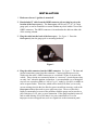
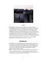
by USER MANUAL FOR GM VEHICLES FIRMWARE VERSION 1.3 www.aeroforcetech.com Made in the USA! WARNING Vehicle operator should focus primary attention to the road while using the Interceptor. The information provided by this device should be observed as part of a normal sequence of observations performed in the operation of the vehicle, as with any gauge or other instrumentation. Interceptor settings should be changed only during conditions when it is safe to do so. Focusing on the road should be the primary concern of the driver. Aeroforce Technology shall not be held liable in any way for any incidental or consequential damages to the vehicle, driver, passengers, and or other involved parties or property occurring while using the Interceptor scan gauge. Aeroforce Technology shall not be liable for technical or editorial errors or omissions made herein, nor for incidental or consequential damages resulting from the furnishing or use of this manual. Aeroforce Technology, Inc. reserves the right to make changes to this document and the product described without notice. Copyright 2005 Aeroforce Technology Inc. All rights reserved. 2 INSTALLATION 1. Make sure the car’s ignition is turned off. 2. Run included 5’ cable from the OBD2 connector (do not plug in yet) to the location of the Interceptor(s). The Interceptor will fit in any 2 1/16” or 52mm gauge pod, or can be mounted in a custom fashion anywhere within 5 feet of the OBD2 connector. The OBD2 connector is located under the dash on either side of the steering column. 3. Plug the cable into the back of the Interceptor. See figure 1. Press the Interceptor(s) into the gauge pod or mounting hardware. Figure 1 4. Plug the cable connector into the OBD2 connector. See figure 2. The data and ground connection come from this connector. Connect separate power wire, which exits the cable’s OBD2 connector, to a switched 12v line or circuit in the vehicle. These circuits are commonly known as “accessory” circuits because they are only “hot” when the ignition is turned on. A recommended way of doing this step is to use a product called an “Add a Circuit”, made by Littelfuse, available at most car parts outlets. These kits, which sell for under $10, allow you to easily use an existing circuit in the fuse block to power an add-on accessory such as the Interceptor without the need to cut or splice any wires. The use of this kit is highly recommended, as most of the problems with the gauge can be traced to a poor selection of a 12v wire, or poor connection. If the gauge randomly turns off and on while driving, 99% of the time it is a poor connection to 12v or an improper circuit was tapped into, such as a signal wire to the instrument panel. 3 Figure 2 5. Turn vehicle on. With the key on and engine off, or engine running, the Interceptor will scan the vehicle for supported parameters from a predetermined list. While the unit powers up, the “Interceptor” and “AeroForce” logo will appear on the display. This only takes a few seconds. Please note that dual Interceptor units may power up sequentially (one at a time) and may take up to 15 seconds to scan the vehicle. If the vehicle supports a parameter on the list, the Interceptor will see this and allow you to display it. See page A1 of these instructions for the list of parameters supported by the Interceptor. Remember that not all parameters are supported by every vehicle, so don’t expect to see all of them on the Interceptor you install in your vehicle. If the vehicle and the Interceptor support the parameter, you will have access to it. OPERATION 1. SCANNING. Once the Interceptor has been installed, with the vehicle on, you will see an upper and lower field containing a description and parameter value. The right button will change the upper parameter field, the left button the lower. One quick push of the button will toggle to the next parameter. Holding the button down will trigger the unit to quickly scroll through the available parameters until the button is released. 2. MENU. Pressing both buttons at the same time will take you to a menu screen. Here you will have eight choices. Use the left button to toggle down to the desired choice. The current selection will be highlighted. Push the right button to select this choice and proceed to the associated screen. 4 Choices are: a) SCAN. This is the standard mode of operation for the unit and the default mode when powered up. In this mode the unit is scanning and displaying data. b) RECORD. Upon selecting record, the unit will return to normal scan mode except the first letter of each field description will be replaced with a square block to indicate that record is active. You may notice that the gauge is scanning much faster in this mode. Once the throttle position reaches 50% or higher, and engine load exceeds 65%, the unit will automatically start recording the displayed data for approximately 35-40 seconds. When recording begins, the display colors will invert as an alert. The recorded file will be saved for replay until record is selected again and the proper record conditions are met. The new file will overwrite the old. The Interceptor will maintain the file even when powered down. If in record mode, you wish to return to normal scan mode, access the menu screen and select record again. This will disable it until selected again via the menu. c) PLAY. Once play is selected the Interceptor will return to the normal scan screen but will show the first frame of a recorded log. You will notice the field descriptions flickering to indicate playback mode is in effect. Pushing the right button will toggle forward to the next frame in chronological order, the left button will toggle backwards, or to the very last frame if done at the beginning of the file. Holding either button down will quickly scroll through the data until the button is released. The backlight will flash every time a new frame is displayed. In other words, push a button once and the light will blink once. Hold a button down and the light will blink quickly as each new frame is displayed. Play will not be selectable if the record buffer is empty. d) DISPLAY DTC’s. Selecting this mode will instruct the Interceptor to acquire and display any diagnostic trouble codes stored in the vehicle’s computer memory. See page A2 for a list and explanation of these codes. e) CLEAR DTC’s. This selection will instruct the Interceptor to clear the vehicle computer of its stored trouble codes. Be sure to make note of any code before clearing it. f) INVERT. This menu option inverts the colors on the display. If the display currently has a black backround with blue characters for example, inverting will make it blue with black characters. A dark backround is called a negative image, and is ideal for low light situations such as driving at night. A light colored or white backround is called a positive image, and is easier to read in bright sunlight. g) DIMMER. Selecting “Dimmer” will take you to a new screen with a brightness value displayed, between 1-3. 1 is the dimmest, 3 the brightest. Using the left button you can raise this value until you reach 3 after which it will restart back at 1. Once the desired brightness is reached press the right button to return to the menu screen. h) SCAN RATE. Choosing scan rate allows you to adjust the speed in which the display will update. When selected, a number from 1 to 6 will appear, the 5 higher the value the slower the scan rate. The left button can be used to alter this value. Select the new value by hitting the right button, which will send you back to the main menu Powering down The Interceptor will automatically shut itself off within seconds of the ignition being turned off. Non-Volatile Memory The Interceptor does not require batteries or a continuous power source to maintain its memory. This means that your data will not be lost if you disconnect the vehicle battery or disconnect the cable from the OBD2 port. Precautions Unplug the Interceptor before disconnecting the battery or performing engine work to prevent damage to the unit. The Interceptor’s display is designed to operate continuously at temperatures up to 122 deg. F (50 deg. C). The display may appear “washed” out for a minute or so if exposed to direct sunlight in hot climates after the car has been parked for an extended period of time. If the gauge is mounted in such a way that it can be exposed to direct sunlight, such as on top of the dash, you may want to consider a windshield shade, or unplugging the display for a minute or two until it and the car cool off a little. Care If the face of the Interceptor needs cleaning, use light pressure with a non-scratching material such as a pre-moistened micro-fiber material made for plastic sunglass lenses. The plastic lens will scratch if anything abrasive is used on it. 6 Limited Warranty Aeroforce Technology warrants this product and its accessories against defects in material and workmanship for a period of 180 days from the date of purchase. Aeroforce Technology will repair or replace this product with new or refurbished products or parts, at Aeroforce’s option, free of charge in the USA. This warranty extends only to the original purchaser. A purchase receipt or other proof of date of original purchase from and authorized dealer (including Aeroforce Technology) is required on order to have warranty service performed. Before sending an Interceptor back for warranty service, you must obtain a Return Materials Authorization number from Aeroforce Technology. This can be done by emailing [email protected] including a description of the problem and date/place of purchase. An RMA number will be returned to you as well as a return address. This warranty covers failures due to material or workmanship defects only. This warranty does not cover cosmetic damage or damage due to accident, misuse, abuse, negligence, commercial use, acts of God, or modifications of, or any part of the product, including accessories. 7 A1-Supported Parameters (PID’S) 1. INTAKE AIR- Intake Air Temperature 2. COOLANT TEMP- Engine Coolant Temperature 3. TRANS TEMP- Transmission Temperature 4. RPM- engine Revolutions Per Minute 5. MAF SENSOR LB/M- Mass Air Flow (lbs/min) 6. MAF FREQUENCY- raw Mass Air Flow sensor output (frequency) 7. MANIFOLD PSI- Manifold Air Pressure (psi)* 8. THROTTLE POS PCT- Throttle Position percentage (0-100%) 9. THROTTLE VOLTS- Throttle Position sensor output (0-5 volts) 10. MILES PER HOUR- Miles Per Hour 11. KNOCK RETARD- Knock Retard (degrees) 12. IGNITION ADVANCE- ignition timing advance 13. PULSE WIDTH- injector #1 pulse width (4&6 cylinder engines) 14. SHORT TRIM B1-short term fuel trim bank#1 15. SHORT TRIM B2-short term fuel trim bank#2 16. LONG TRIM B1-long term fuel trim bank#1 17. LONG TRIM B2-long term fuel trim bank#2 18. OXYGEN SENSOR B1-O2 bank 1 sensor in millivolts 19. OXYGEN SENSOR B2-O2 bank 2 sensor in millivolts 20. RUN TIME MINS- engine run time is tenths of seconds since last engine start 21. BATTERY VOLTAGE- Alternator/battery output voltage 22. IAC POSITION- Idle Air Control counts (position of Idle Air Control valve) 23. PULSE WIDTH B1-injector Pulse Width for bank 1 (8 cylinder engines) 24. PULSE WIDTH B2-injector Pulse Width for bank 2 (8 cylinder engines) 25. ENGINE LOAD-calculated Engine Load (0-100%) 26. ENGINE OIL PRESSURE (some 8 cylinder engines) *Will read in PSI (pounds per square inch) whether in vacuum or under boost (factory forced induction applications). Normal range is approximately -9 psi at idle. 8 A2-DIAGNOSTIC TROUBLE CODES (DTC’s) The Interceptor will display the code in the hex format of XXXX. See Table 1 below for explanation and interpretation of these Interceptor codes. Replace with this… ↓ If the first hex digit is this → 0 P0 Powertrain codes – SAE defined 1 P1 “ “ – manufacturer defined 2 P2 “ “ – SAE defined 3 P3 “ “ – jointly defined 4 C0 Chassis Codes – SAE defined 5 C1 “ “ – manufacturer defined 6 C2 “ “ – manufacturer defined 7 C3 “ “ – reserved for future 8 B0 Body Codes – SAE defined 9 B1 “ “ – manufacturer defined A B2 “ “ – manufacturer defined B B3 “ “ – reserved for future C U0 Network Codes – SAE defined D U1 “ “ – manufacturer defined E U2 “ “ – manufacturer defined F U3 “ “ – reserved for future TABLE 1 For example, if code 0107 is returned, replace the first “0” with P0, resulting in code P0107. Looking up this code reveals: “ P0107-Manifold Absolute Pressure/Barometric Pressure Circuit Low Input” There are many resources that fully explain these codes including the specific vehicle shop manual, web sites, as well as automotive self-help guides. A list of power train diagnostic trouble code explanations can be found on our web site at 9 http://www.aeroforcetech.com/files/Partial_list_of_diagnostic_trouble_codes.txt The http://www.aeroforcetech.com/files/Partial_list_of_diagnostic_trouble_codes.txt. web site www.troublecodes.net/OBD2/ is another source of explanation for these codes. 10 A3-TIPS AND VEHICLE SPECIFIC NOTES ’04 Pontiac Grand Prix: A common mount for the Interceptor is in the top left vent next to the steering wheel. If mounted here, hot air cannot be blown directly on the unit for extending periods of time. Insulation should be placed behind the Interceptor if hot air is blown through this vent when the heater is on for example. 4800 Vortec: Throttle voltage reads “0” all the time. It is not a supported parameter on this motor. Some parameters are not supported by all vehicles but they may still be displayed as a “dummy” value in place of a real one. Certain manual transmission cars will display a false transmission temperature, and some V8’s will display an erroneous oil pressure for example. These “dummy” values may be obviously incorrect, or may look normal at first but never change. ’97 Pontiac Grand Prix: Ignition advance will be displayed as a negative number. 2000-2001 Grand Prix: There has been a couple reports of the Pass Key III system rejecting the keys when this gauge is plugged in when the car is started in extremely cold temperatures (below 15 degrees F). Therefore it is recommended to unplug the gauge before starting these cars in these extremely cold temperatures, and plugging it back in a few seconds after the car is started. There is no need to disconnect the power wire though. 2000-2003 full size GM SUV’s and Corvette: Owners my find that scan speeds need to be raised to 3 or higher to prevent false error messages on the vehicles instrument panel. These vehicles have extremely high data volumes with slower than desirable bus hardware. ‘96/’97 V8 GM trucks: A smaller set of parameters are supported for these vehicles. You may only see 9-10 as opposed to 20+ for later years. Saturn Ion Redline/Chevy Cobalt SS: You should have received a unique version of the Interceptor specific to your vehicle. These versions display 2 parameters not shown on the page A1 list. These are: 1. Intake Air2 temp: This is the temperature of the air exiting the intercooler. This is a very useful tuning aid in determining the efficiency of the intercooler. The lower this temperature the better. 2. SC inlet pressure: This indicates the pressure at the inlet of the supercharger. It is the difference between the barometric pressure and the absolute pressure at the supercharger inlet. The higher the value, the more 11 restrictive the intake/air filter which is especially useful to know under boost. This can be used to determine the effectiveness of aftermarket cold air intakes. If the value of this parameter drops at wide open throttle after installing a new intake kit, the restriction has been reduced and more power should be achieved. 12