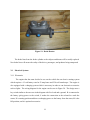
1
Team 7 Alternative Farming Solutions Vehicle Seth Weaver (ME) Reuben Swinkels (ME) Matt Hoogstrate (ME) Jon Goorhouse (ME) Ben Byma (ME) FINAL REPORT ENGINEERING 340 SENIOR DESIGN Copyright © 2012, Team 7 and Calvin College Abstract This report summarizes the research and design of a small utility vehicle. Alternative Farming Solutions Vehicle, also known as Team 7, has chosen the senior design project of building a small, low cost, durable vehicle for developing countries. Team 7 contacted the CRC World headquarters in search of a contact that could act as a customer for the project. Davis Omanyo was notified of the opportunity and replied with an immediate need in his hometown in the Samia District of Kenya. Davis had a need for a small vehicle that could plant, plow, and transport produce. Team 7 designed and constructed this vehicle with his needs in mind, to develop a prototype that will be useful for a particular customer. The goal was to design and build the vehicle with parts that are readily available as well as cheap and durable. i Table of Contents ENGINEERING 340 SENIOR DESIGN.................................................................................................. Copyright ..................................................................................................................................................... Abstract ......................................................................................................................................................i Table of Contents .................................................................................................................................... ii Table of Figures ...................................................................................................................................... iv Table of Tables .......................................................................................................................................... v 1 2 Introduction ...................................................................................................................................... 1 1.1 The Project............................................................................................................................................... 1 1.1.1 Problem Definition....................................................................................................................................... 1 1.1.2 Customer/Solution........................................................................................................................................ 1 1.2 Design Norms ........................................................................................................................................ 2 1.2.1 Cultural Appropriateness ........................................................................................................................ 2 1.2.2 Integrity/Trust ............................................................................................................................................ 2 1.3 The Team ................................................................................................................................................. 2 1.4 The Class .................................................................................................................................................. 3 1.5 Acknowledgements ................................................................................................................................ 3 Project Management ...................................................................................................................... 4 2.1 2.2 3 Schedule .................................................................................................................................................... 4 Budget ....................................................................................................................................................... 4 Project Specifications ..................................................................................................................... 6 3.1 Design Summary .................................................................................................................................... 6 3.2 Engine ....................................................................................................................................................... 6 3.2.1 Alternatives .................................................................................................................................................... 6 3.2.2 Selected Engine ............................................................................................................................................. 9 3.3 Power Transmission System ............................................................................................................. 10 3.3.1 Clutch ............................................................................................................................................................. 10 3.3.2 Alternative Transmissions ....................................................................................................................... 11 3.3.3 Cost ................................................................................................................................................................. 13 3.3.3.1 3.3.3.2 3.3.3.3 Lawn Mower Transaxle ........................................................................................................................................13 Car Transmission .....................................................................................................................................................13 Hydrostatic Transmission ...................................................................................................................................13 3.3.4 Transmission ................................................................................................................................................ 14 3.4 Final Drivetrain Design ................................................................................................................... 15 3.5 Tilt Bed .................................................................................................................................................. 16 3.6 Suspension............................................................................................................................................. 18 3.6.1 Front................................................................................................................................................................ 18 3.6.2 Rear ................................................................................................................................................................. 20 3.7 Steering .................................................................................................................................................. 21 3.8 Brakes .................................................................................................................................................... 23 3.9 Electrical Systems ............................................................................................................................... 25 ii 3.9.1 Electronics .................................................................................................................................................... 25 3.9.2 Lights.............................................................................................................................................................. 26 3.10 Frame ..................................................................................................................................................... 27 3.11 Plow ........................................................................................................................................................ 29 3.11.1 Alternatives .................................................................................................................................................. 29 3.11.2 Selected Plow............................................................................................................................................... 32 3.12 Planter.................................................................................................................................................... 33 4 Testing .............................................................................................................................................. 35 5 Project Summary........................................................................................................................... 39 6 5.1 5.2 5.3 Future Suggestions ........................................................................................................................... 39 Final Prototype .................................................................................................................................. 40 Conclusion ........................................................................................................................................... 40 Appendices ...................................................................................................................................... 41 6.1 Maintenance & User Manual ......................................................................................................... 41 6.1.1 Maintenance ............................................................................................................................................... 41 6.1.1.1 6.1.1.2 6.1.2 6.1.2.1 6.1.2.2 6.1.2.3 6.1.2.4 Engine ...........................................................................................................................................................................41 Vehicle Components ...............................................................................................................................................41 Operation ..................................................................................................................................................... 43 Driving ..........................................................................................................................................................................43 Dumping ......................................................................................................................................................................43 Plowing ........................................................................................................................................................................43 Planting ........................................................................................................................................................................44 6.2 Calculations .......................................................................................................................................... 44 6.2.1 Bed/Frame Analysis .................................................................................................................................. 44 6.2.2 Weldment Calculations............................................................................................................................. 46 6.2.3 Leaf Spring Calculations .......................................................................................................................... 46 6.2.4 Driveshaft Calculations ............................................................................................................................ 47 6.3 Work Breakdown ................................................................................................................................ 48 6.4 Suspension Parts.................................................................................................................................. 51 iii Table of Figures Figure 1: Kohler KD425-2, 18.8 Horsepower Diesel .................................................................................. 6 Figure 2: Power Curve for Diesel Kohler Engine ....................................................................................... 7 Figure 3: Kohler CH620, 18 horsepower Gas Engine ................................................................................ 8 Figure 4: Kohler CH15, 15 Horsepower Gas Engine ................................................................................. 9 Figure 5: Clutch System Setup .................................................................................................................. 11 Figure 6: Automatic Transmission............................................................................................................. 12 Figure 7: Manual Transmission ................................................................................................................. 12 Figure 8: Hydrostatic Transmission ........................................................................................................... 13 Figure 9: Lawn Mower Transaxle.............................................................................................................. 14 Figure 10: Mounted Drivetrain ................................................................................................................... 15 Figure 11: Mounted Transaxle and Driveshaft ........................................................................................... 16 Figure 12: Winch Mounted to Roll Cage ................................................................................................... 17 Figure 13: Front Suspension ...................................................................................................................... 20 Figure 14: Rear Suspension ....................................................................................................................... 21 Figure 15: CAD Suspension Model ............................................................................................................ 22 Figure 16: Front Steering Diagram ............................................................................................................ 22 Figure 17: Front Brake Calipers................................................................................................................. 23 Figure 18: Rear Drum Brakes .................................................................................................................... 24 Figure 19: Brake Booster ........................................................................................................................... 25 Figure 20: Engine Wiring Diagram ............................................................................................................ 26 Figure 21: Wiring Diagram for Lights ....................................................................................................... 27 Figure 22: Rear Frame ............................................................................................................................... 28 Figure 23: Harrow Plow............................................................................................................................. 30 Figure 24: Potato Plow............................................................................................................................... 31 Figure 25: Chisel Plow............................................................................................................................... 32 Figure 26: Single Bottom Plow Attachment .............................................................................................. 33 Figure 27: Pivoting Drop Seed Planter ....................................................................................................... 34 Figure 28: Engine Mount for Testing ......................................................................................................... 35 Figure 29: Final Prototype .......................................................................................................................... 40 Figure 30: Manufacturer Recommended Maintenance .............................................................................. 41 Figure 31: Winch Assembly and Parts ........................................................................................................ 42 iv Table of Tables Table 1: Vehicle Costs ................................................................................................................................. 4 Table 2: Decision Matrix for Bed Lift System........................................................................................... 18 Table 3: Decision Matrix of Front Suspension Options............................................................................. 19 Table 4: Summary of Stress Calculations .................................................................................................. 29 Table 5: Work Breakdown ......................................................................................................................... 48 v 1 Introduction 1.1 The Project 1.1.1 Problem Definition In many third world countries there is need for small, inexpensive, all-terrain vehicles. These types of vehicles need the power capabilities of a small tractor, yet the traveling speeds of a small car. These vehicles can be used on the farms, bringing people back and forth from town, or used to transport produce and materials. Some of the important attributes these vehicles need to fulfill include: integrating a small plow for use in the fields, having a tilt bed for carrying produce etc., and possible additional features such as seeding machinery. Price, size, weight, fuel, and usability are some of the many constraining issues which the team faces. The team is designing and fabricating a vehicle to meet the specifications and requirements determined from an actual customer. 1.1.2 Customer/Solution To find this customer, the team went to the CRC Global Headquarters. After a quick search of all the ministry areas, there was a need found in Eastern Africa. Specifically, there was a need in the Samia District of Kenya. Davis Omanyo is the main contact in that region. Davis is the CRWRC team leader in Eastern Africa, and has an immediate need for this type of vehicle. He runs a small demonstration farm in his hometown of the Samia District of Kenya. Here, he currently teaches women how to plant, maintain, and harvest amaranth. He would like to expand this operation to grow maize (corn), millet, sorghum, peanuts (ground nuts), beans, and peas. Davis has made it clear that he would like this vehicle to be able to plant, plow, and transport produce. He has also mentioned that a generator, high ground clearance, and good traction will be important. Based on Davis‟ comments for what would be important for a useful farming vehicle, the team plans on constructing a vehicle which will abide by these requirements. The goal is to construct a vehicle which can be used to drive to a town, has a tilt bed, will be able to plow and possibly seed, will have a generator, and will be durable enough to withstand the different environments in which it will be used. 1 1.2 Design Norms 1.2.1 Cultural Appropriateness One of the team‟s primary concerns was making sure the design was appropriate for the culture in which it would be used. This was done by considering what materials we used, what fuel type we pick, and what emissions we produce. The parts and materials will need to be available in case repairs or replacements are necessary. The fuel type must be readily available otherwise the design becomes inoperable. The vehicle needs to be safe to drive and not produce hazardous emissions that will hard operators or bystanders. 1.2.2 Integrity/Trust Another important design norm the team considered was integrity throughout the design; this was done by incorporating a simple yet useful design. The utility vehicle will be easy to use without any issues. This will help insure the trust between the recipient and donating organization. The design will be tested to guarantee proper functionality of every component as well as include an operator‟s manual. 1.3 The Team The team is composed of five mechanical engineering students; Seth Weaver, Ben Byma, Reuben Swinkels, Matt Hoogstrate, and Jon Goorhouse. All team members have different skills and backgrounds, which gives a well-rounded team. Seth has a strong automotive background, and will be a great contribution to the physical build of the vehicle. Ben is very interested in design and calculations, and will be a great contribution to the design and trouble shooting of the vehicle. Reuben has a good knowledge in the concepts of what needs to go into a vehicle, as well 2 as an interest in problem solving, which will be useful in the design and build. Matt has experience in electrical wiring, and will be able to contribute to the necessary electric engineering and design associated with the project. Lastly, Jon is very well versed with computer engineering software. He will be a good contribution to the design of vehicle, the calculations involved, and with maintaining and updating the project website. 1.4 The Class This senior design project is the final project and capstone to the engineering program at Calvin College. This design project is part of the Engineering 339 (fall) and Engineering 340 (spring) senior design classes at Calvin. In addition to designing and building this vehicle, the class has different lectures that prepare the team for the work that needs to be done on the project, but also for the transition from school into full time employment. The course aims to teach the students to “perform in a realistic engineering working environment that integrates team design work, computer usage, documentation, project management, and supervision.”1 The team‟s goal for this design class is to design something that will help show our Christian backgrounds, and have an overall positive effect on the world, even if on a small scale. 1.5 Acknowledgements Ned Nelson – Project Advisor Phil Jasper – Fabrication Mentor and Advisor Joel Lautenbach – CRWRC contact Davis Omanyo – Connection in Kenya and end user Patricia Fisher – CRC Contact Ren Tubergen – Industrial Consultant Mike Ohlman – Berger Chevrolet Mike Kienast – Donated tires Mark Kienast – Donated Ford Ranger Doug Kok – Tire mounting and painting Justin Hyma – Bauer Truck Parts 1 https://docs.google.com/document/pub?id=13uHbBUCFovpt9do7YmHZsh6HnYp-WXjVMNVmqOWkHN0&pli=1 3 2 Project Management 2.1 Schedule The team‟s approach to making a schedule involved a few steps. Step one was to create a list including all of the assignments due dates for the first semester. Step two was to create another list that included everything that needed to be completed for the project to be finished at the end of the school year. Step three was to create a hierarchy of the tasks from the two lists based on which ones had to be done before others. The completed schedule can be seen in Appendix section 7.2. The schedule for the final half of the project has a multi-level approach so that multiple tasks can be worked on at the same time. 2.2 Budget The team has been asked by our recipient for a few specific vehicle operations. These vehicle operations include planting, plowing, and transporting produce. Implementing these operations has caused the team budget to be higher than what was provided. The team was initially given $500 for the vehicle, and applied for a higher budget. The approved budget was $2350. The current projected costs of the vehicle can be seen below in Table 1. Table 1: Vehicle Costs Item Price ($) Frame Donated Tires Donated Drive/Driven Clutch 327.85 Transaxle 375.00 Winch 99.95 Front Struts 209.19 Drive Belts 32.70 4 Plow 249.00 Rear Shocks/Mounts 70.00 Bearings 20.00 Rear Brake Parts 295.12 Steel 2 x 2 83.74 Lumber and Hardware 107.23 Brake Cylinder 36.65 Square Tubing Plug 25.24 16,000 Lb. Pulley 25.45 Sprockets 56.16 Golf Cart Seat 135.00 Ball Joints 80.00 5 3 Project Specifications 3.1 Design Summary 3.2 Engine 3.2.1 Alternatives There were many different things that the team needed to consider when looking into an engine for the vehicle. The main constraint for the engine was cost. The goal for the team is to come up with a low budget utility vehicle. Previous groups, who actually entered into the BUV competition, would be given a 10 horsepower diesel engine. The team decided that since this particular vehicle was supposed to plow, in addition to meeting most specifications of the previous BUV teams, a bigger engine would be desirable. The first thing that was researched was fuel availability. The findings were that both gasoline and diesel fuels were fairly readily available in most of rural third world countries. This opened up the potential for either engine. Since diesel engines are known for producing more torque2, this was the first possible option the team looked into. This was a good option for the vehicle because the engine would produce more torque than the gas equivalent engine, which is beneficial for plowing as well; the diesel fuel is slightly more easily accessible. The primary diesel engine of interest was the Kohler KD425-2, seen in Figure 1. Figure 1: Kohler KD425-2, 18.8 Horsepower Diesel3 2 3 http://robotics.caltech.edu/~mason/ramblings/dieselTorque.html http://www.kohlerengines.com/onlinecatalog/productDetail.htm?productNumber=KD425-2 6 The KD425 is an 18.8 horsepower diesel, air cooled engine. This engine was in the desired horsepower range, and was diesel which was important because of the torque assumption previously made. In order to determine the type of gearing needed for plowing and for the generator, the team needed to find the actual torque the engine created. The power curve for this engine can be seen in Figure 2. Figure 2: Power Curve for Diesel Kohler Engine4 The torque of the engine, with respect to engine rpm, can be seen in the red „MN‟ line. This shows that a maximum torque of 42 Nm, or 31 ft-lbs, is obtained at roughly 2200 rpm. This gave the team a good idea of what was to be expected out of a diesel engine around this size. The next option the team looked into was a comparison to the gas engine. The team looked into similar brands, and similar horsepower engines, to try to eliminate factors, such as differences in quality builds in manufacturers, that might give a bad 4 http://www.kohlerengines.com/onlinecatalog/pdf/kd425_2.pdf 7 representation of the differences in engines. For the gas engine, the team looked at the Kohler CH620 gas engine, seen in Figure 3. Figure 3: Kohler CH620, 18 horsepower Gas Engine5 This 18 horsepower gas engine is very similar in size to the 18.8 horsepower diesel Kohler engine. They both are air cooled, horizontal drive, and 2 cylinder engines. The sizes are similar, but the weights are slightly different. This aluminum block engine weighs about 90 lbs, which is about 50 lbs lighter than the iron block diesel engine.6 Although this difference in weight would have an overall effect on the vehicle, it does not have a direct effect on the horsepower or torque the engines would put out. The power curve for this engine could not be found, however, the peak torque was still given. The gas engine put out 32.2 ft-lbs at approximately 3600 rpm7, which is actually more than the diesel engine which had 0.8 more horsepower. Although the engine would be running at a higher rpm, this showed the team that in these smaller engines, the diesel engine did not necessarily produce more torque. This was a 5 http://www.kohlerengines.com/onlinecatalog/productDetail.htm?productNumber=Command%20PRO%20CH18/C H620 6 http://www.kohlerengines.com/onlinecatalog/productDetail.htm?productNumber=KD425-2 7 http://www.kohlerengines.com/onlinecatalog/productDetail.htm?productNumber=Command%20PRO%20CH18/C H620 8 large surprise, which took away a large factor of why the diesel engine would be more suitable for this project. The last thing done to compare these engines was looking at the cost. This ended up being the major deciding factor of what engine type was chosen. Most new diesel engines, around 15-20 horsepower would cost approximately $3000-$5000. When looking into gas, the team found that new engines of the same horsepower would range from $1500-$2500. This was a significant difference in price that the team could not overlook. However, since the team only has an initial budget of $500, and is trying to make the vehicle as low budged as possible, a different alternative was found. 3.2.2 Selected Engine Based on the investigations of the diesel compared to gas engines, it was clear that gas has no large disadvantage for this project. Therefore, when the team received the information that the Calvin College Engineering Department had a 15 horsepower, Kohler gas engine that could be donated, the team investigated the possibility of using this engine. The specific engine is the Kohler CH15 and can be seen in Figure 4. Figure 4: Kohler CH15, 15 Horsepower Gas Engine 9 This 15 horsepower gas engine was slightly different than the previous engines. It obviously had slightly less horsepower, and was only one cylinder instead of two. The weight and dimensions were similar to that of the CH620. This engine produced a peak torque of 24.8 ft-lbs at 2400 rpm.8 Although this was less than the 18 horsepower engine, the team decided that with the correct gearing, and the slow speed at which plowing is done, that amount of torque would be more than adequate. The final engine selected for use, was the Kohler CH15. It was selected because it fit the criteria needed for an engine discussed above. The fuel type (gas) was readily available in most rural places, the torque would be sufficient for plowing and transportation, and most importantly, the cost was minimal. 3.3 Power Transmission System 3.3.1 Clutch To transmit power from the engine to the transaxle, a centrifugal clutch will be used. There are many different types of centrifugal clutches available to the public. The most common of these clutches are Comet Clutches. The team has decided to use a series 40 Comet Clutch. These clutches are designed for 8-18 horsepower engines9. The comet 40 series clutches engage at 1600 rpm‟s, which will fit the Kohler 15 horsepower engine perfectly. This clutch system has a primary (driving) clutch and a secondary (driven) clutch. The secondary clutch will be mounted on a jackshaft which transmits power to other pulleys located on the jackshaft. The power will then be transmitted to a transaxle. The clutch setup can be seen below in Figure 5. 8 http://www.kohlerengines.com/onlinecatalog/productDetail.htm?productNumber=Command%20PRO%20CH15/C H450 9 http://www.gokartsupply.com/4044seri.htm 10 Figure 5: Clutch System Setup10 3.3.2 Alternative Transmissions The team also looked into other alternatives. Some of these alternatives included transmissions from small cars and hydrostatic transmissions from lawn tractors, other utility vehicles, and golf carts/go carts. The main reason that none of these types of transmissions were used was size and cost. The reason that a small automatic car transmission was not used was because of the power required to run an automatic transmission. To be able to cover the needs of the vehicle, there needed to be minimum power loss in the transmission. The reason that a manual car transmission was not used was because of the clutch setup. The team focused on ease of use. Therefore, teaching others how to operate a clutch was out of the question. A picture of an automatic and manual transmission can be seen below in Figure 6 and Figure 7, respectively. 10 http://www.hoffcocomet.com/EpiphanyWeb/flexpage.aspx?ID=75 11 Figure 6: Automatic Transmission11 Figure 7: Manual Transmission12 A hydrostatic transmission was not used for much of the same reason. Hydrostatic transmissions run off hydraulic fluid which gets pressurized from a pump, which would be run off the engine power. Again, maximum power was needed by the engine to drive the vehicle. The team also wanted to minimize problematic options on the vehicle. Having hydraulics on the vehicle would increase the probability of problems. A hydrostatic transmission can be seen in Figure 8. 11 12 http://www.eagleclassicsinc.com/eagle-classics-inc/car-transmission-repair-rock-hill/ http://adaptiveblue.img.s3.amazonaws.com/topics/p/manual_transmission/small 12 Figure 8: Hydrostatic Transmission13 Other utility vehicles were also looked into. Many of these transmissions are continuously variable. The team did not use this type for many reasons. Overall, the cost was the determining factor that led the team to reject this type of transmission. 3.3.3 Cost 3.3.3.1 Lawn Mower Transaxle The cost of a lawn mower transmission varies greatly depending on the year, size, hours of use, and model of transmission. Most lawn mower transmission cost between $150 and $400. 3.3.3.2 Car Transmission Car transmissions vary in price due to mileage and type. Most of these transmissions vary from $300 to $2000. 3.3.3.3 Hydrostatic Transmission Hydrostatic transmissions vary in price due to the year, size, hours of use, and model. These transmissions vary from $175 to $200 13 http://www.fordfalcon2000.com/cgi-bin/pic.pl?id=T52 13 3.3.4 Transmission As requested by Davis Omanyo, the utility vehicle will be used to plow, plant, and transport produce. To do this, a transmission will be required to transmit power in different gear ratios for the different applications. A low gear will be required for plowing, while higher gears are required for driving at higher speeds. To plow at 2mph, a total reduction of 30:1 will be needed. To drive at 20 mph, a reduction of 3:1 will be needed. The range of gear ratios required has been hard to find. These calculations can be seen in Appendix 7.1.4. The team looked into many different transmissions and finally found that the best transmission for the project is the type used by a riding lawn mower. These transmissions are typically 5 or 6 gears, along with a reverse gear. This transmission can be seen below in Figure 9. The chosen transmission was a Peerless transmission with 6 forward gears and a reverse gear. It is designed for 18 horsepower engines and will thus be strong enough for our 15 horsepower engine. Figure 9: Lawn Mower Transaxle14 The final gear ratios, along with corresponding speeds will be determined after exact components are bought. Ideally, the vehicle will plow at 2 mph and will carry produce at 20 mph. 14 http://www.onlineauction.com/index.php?page=auction:view_item&auction_id=1040252 14 3.4 Final Drivetrain Design The final design for the drivetrain can be seen in the following image. Figure 10: Mounted Drivetrain The comet clutch detailed above was connected to the driveshaft of the engine via the driving clutch, which was keyed and bolted in place. This connects to the driven clutch via a V belt. The driven clutch is mounted on a jack-shaft that spins on two bearings. The driven clutch is keyed in the jack-shaft and is held in place with collars. Also keyed onto the jack-shaft is a sprocket which is connected to a sprocket on the transaxle via a chain (see below picture for chain updated chain drive) discussed above. A better view of this connection can be seen in Figure 11 below. 15 Figure 11: Mounted Transaxle and Driveshaft The power is then transferred from one of the axles of the transaxle, to the driveshaft of the old ford ranger (reduced in size). A plate was machined and welded onto the axle to connect the driveshaft. The other axle coming out of the transaxle was held in place using a collar and welding it in place. From the driveshaft, the power goes through the Ford Rangers rear differential and two the wheels. 3.5 Tilt Bed One of the very useful options desired for the vehicle was a dumping bed. Many commercial vehicles feature this type of system, and its possible applications are highly desirable for agricultural use. Most modern systems feature a single hydraulic piston acting either directly on the bed frame or indirectly via a scissor lift frame. Other possible systems feature a winch or crank system. The major advantage of a hydraulic system was the amount of power it could deliver to raise the bed. Its disadvantages were its overall cost and complexity. The two winch systems considered were a tower boom type lift and a scissor lift. The tower boom would feature a winch or crank mounted at frame level with cable running up to a pulley on the roll bar and then back down to the base of the bed. Activating the winch or crank would cause the bed to lift. 16 This system would be very simple and inexpensive, but could pose some reliability and capability issues. The other winch option considered would be similarly mounted, but the winch cable would run to a scissor lift joint under the bed similar to those used in a hydraulic system. Activating the winch or crank would cause the scissor to straighten and lift the bed. This system is an in between on most criteria considered. After considering several criterions and the importance each one held for the project, the team decided to use the boom tower design. Although it was not as impressive or as powerful as the hydraulic system, it was more cost effective and had a simpler design. Below is a photo of the winch system mounted at the base of the boom tower (also acting as a roll cage). Figure 12: Winch Mounted to Roll Cage The team felt that this choice best reflects the design norms focused on for the project. Cultural appropriateness would dictate that the vehicle be simple and reliable enough to be used consistently and repaired easily by the user. This also ties directly in with trust. Below is a decision matrix that illustrates how the team selected the type of lift system to be used for the vehicle. 17 Table 2: Decision Matrix for Bed Lift System Factor Winch tower Winch Scissor Hydraulic cost 5 5 4 2 ease of design 2 5 3 2 ease of use 4 4 5 5 ease of build 3 4 3 3 maintenance 3 4 3 3 capability 4 3 4 5 87 80 72 TOTAL 3.6 Weight Suspension 3.6.1 Front In order to transport riders and cargo safely and comfortably along roadways, the front suspension of the vehicle must have enough travel while still controlling damping. The team has looked at several different types of suspensions and created a decision matrix comparing them which can be seen in Table 3 below. The two designs that are found to be most desired are the double wishbone and the MacPherson strut. The design aspects which are most important in choosing the best suspension type are the cost and durability of the design. The cost was most heavily weighted because the major limiting factor of the vehicle is cost. It must still be reliable, however, so durability was also heavily weighted. 18 Table 3: Decision Matrix of Front Suspension Options Cost Simplicity Camber Travel Durability Suspension Type/Weight 8 6 4 4 7 total MacPherson Strut 9 8 5 6 6 206 Double Wishbone 8 7 9 7 7 219 Trailing Arm 7 6 5 4 5 163 The team has decided that a double wishbone type suspension will be the most effective solution. In order to keep costs low the team fabricated A-arms from 1 in. square steel tubing. The arms are designed so that the front and rear wheels of the vehicle are in line. The rear shocks from a Chevy Caviler are used for the front suspension. Because the arms are narrow the team decided it was most important for the travel of the front tires to move upward. The shocks are mounted so that the vehicle rides with a normal load of a couple of passengers sitting in the front with the A-arms at a slight downward angle. The front suspension design can be seen in Figure 13 below. 19 Figure 13: Front Suspension 3.6.2 Rear The vehicles rear suspension is the leaf springs from the donated Ranger pickup. Ranger leaf springs are rated for as much, if not more weight than what we will be using it for. The mounts for the springs were highly rusted so the team decided that replacing them was necessary 20 to provide a safe product for our customer. The rear shock absorbers from the ranger had lost most of their damping power and were rusting out as well, so the team also replaced these which can be seen in Figure 14 below. Figure 14: Rear Suspension 3.7 Steering The steering system from the Ford Ranger was initially going to be used for the utility vehicle. After the assembly began, the team realized that the spindles from the Ford Ranger will not work as planned. Therefore, the front steering from the Ranger will also not work. After front spindles from a Chevy S-10 were acquired, the remaining system needed to be designed. The steering linkage was designed in autoCAD. Different linkages were drawn and constrained to determine turning limits and angles. This design can be seen below in Figure 15. 21 Figure 15: CAD Suspension Model A manual steering gear box was bought from a local junk yard. Tie rod ends from the Chevy S-10 were reused to fit the S-10 spindles. Linkages were then designed and built to connect the tie rod ends and the steering gear box. The light weight vehicle allowed for the hydraulic booster to be left off. The steering setup can be seen below in Figure 16. Figure 16: Front Steering Diagram 22 3.8 Brakes The front brake system was initially going to be reused from the Ford Ranger but when the Ranger spindles were no longer going to be used, different brakes were needed. Since the new spindles came from an S-10, new calipers and brake pads were bought and attached to the new spindles. A non-powered brake cylinder was also purchased to power the hydraulic brakes. The front caliper, brake pads, and rotors can be seen below in figure 17. Figure 17: Front Brake Calipers The rear drum brakes from the Ford Ranger were rebuilt and assembled to assure maximum safety. The new parts included new pistons, new pads, new springs, and new brake drums. A picture of rear drum brakes can be seen below in Figure 18. 23 Figure 18: Rear Drum Brakes The brake booster from the Ford Ranger will not be reused. The old brake fluid will be taken out and will be replaced with new. The new brake cylinder will be mounted into the correct position so that when the brake pedal is applied the brake cylinder will compress brake fluid in the lines and press the brake pads against the brake rotors. This will also cause the rear brake pistons to expand and push the pads onto the drums in the rear. A picture of a brake cylinder can be seen in Figure 19, below. 24 Figure 19: Brake Booster The brake lines from the brake cylinder to the calipers and drums will be totally replaced. New brake lines will ensure the safety of the driver, passengers, and products being transported. 3.9 Electrical Systems 3.9.1 Electronics The engine that the team decided to use on the vehicle has an electric starting system which requires a 12 volt battery rated at 32 amp hours and 250 cold crank amps. The engine is also equipped with a charging system which is necessary in order to run electronic accessories such as lights. The wiring diagram for the engine can be seen in Figure 20. The design uses a key switch similar to the one seen in the diagram with five leads and a ground. B is connected to the battery giving power to the switch, S makes the connection at the solenoid to crank the starter, R is running position and draws recharging power to the battery from the stator, M is the kill position, and A is optional accessories. 25 Figure 20: Engine Wiring Diagram15 3.9.2 Lights In order to provide safe travel at any time of the day the vehicle is equipped with front headlights and rear running and brake lights. The team used basic halogen headlamps which were determined to provide sufficient headlight for the vehicle, spare bulbs are provided with the vehicle understanding that these are something that often fail and may be a hassle to find quick replacements. Headlamps are mounted directly to the front frame and wired to the battery through a switch mounted near the seat; a wiring diagram can be seen in Figure 21 below. The rear lights are mounted on the bottom of the rear frame under the tail gate out of the way from falling objects when the bed is lifted; the running light bulb is connected through the key switch so they are always on when the vehicle is running and the brake bulb is connected through a switch on the brake pedal. 15 http://www.kohlerengines.com/onlinecatalog/pdf/tp_2402_a.pdf 26 Figure 21: Wiring Diagram for Lights 3.10 Frame The frame of the bed rests on the existing frame of a donated Ford Ranger. The rear half of the Ranger frame is used for the project as seen in figure 22 and the front was recycled. The front frame section was custom fabricated from 2” x 2” square steel tubing with 1/8” thick wall as was the bed frame. This material was selected because of its availability, strength and ease of fabrication. The floor of the bed was made from 6” x ¾” wooden planks to keep weight low, and will measure 6‟ x 5‟. 27 Figure 22: Rear Frame The design goal for payload was 1500 pounds of static loading. In the calculations, a dynamic load was estimated to be at least twice the static load, for example going over a large bump and the entire load bouncing up and coming down, the calculations used a dynamic loading factor of 2.5. The calculations show several worst case of the full load distributed to one frame member of two different lengths and as a cantilever type loading for the same two lengths to demonstrate safety factors. The final calculations show safety factors for a more typical loading. See Appendix 7.1.1 for complete details of frame stress calculations. A summary of the maximum stresses and safety factors for given scenarios can be seen in Table 4. 28 Table 4: Summary of Stress Calculations Scenario Max Stress Safety (psi) Factor Distributed Load across 3ft 33750 1.067 Distributed Load across 2ft 22500 1.6 Typical Load across 3ft 10120 3.556 Typical Load across 2ft 3000 12 The team‟s design called for much of the frame to be welded together at various points. In order to ensure that the welds are strong enough to support the payload of the vehicle, the team did weldment calculations. The same assumptions were made as previous about dynamic loading. The team also assumed an unrealistic worst case scenario for the weldment calculations, to be sure that the welds would meet the design specifications. The assumption was the entire load acting on a single beam in a cantilever type arrangement, and includes torsion. Based on published data by the American Welding Society (AWS) specific to the chosen material and the calculations performed, the welds can be no smaller than 1/8” wide and can go up to 2.7” wide. Again, the upper limit is unrealistic, but shows that the material selected is strong enough for the application. Complete calculations for the weldments can be found in Appendix7.1.2. 3.11 Plow 3.11.1 Alternatives Harrows are another type of plow. Many times, tractors pull many of these at once. In many cases, fields were bottom plowed and then left to dry. Harrows are used to level and even out the dirt before planting. Since this type of plow does not overturn the dirt, the team will not be using this type of plow. A harrow plow can be seen below in Figure 23. 29 Figure 23: Harrow Plow16 A third type of plow that was considered was the potato plow. A potato plow is used to overturn dirt similar to the single bottom. Although this plow would be right for the need, the power needed to pull this plow is much higher than the previous possibilities. Therefore, this plow idea was not considered further. The potato plow can be seen below in Figure 24. 16 http://forums.atvconnection.com/hunting-trapping-game-management/291401-minimum-engine-size-pullingplow.html 30 Figure 24: Potato Plow17 The final type of plow that was considered was called the chisel plow. Chisel plows can be adjusted to till at deep or shallow depths. These types of plows normally need 10 horsepower per shank to pull.18 The issue with this type is that it does not overturn the soil. This is the major design criteria determined by the customer. A chisel plow can be seen below in Figure 23. 17 18 http://www.robertsfarmequipment.com/Kodiak.html http://www.marketfarm.com/cfms/chisel_plow.cfm 31 Figure 25: Chisel Plow19 3.11.2 Selected Plow As requested, the plowing device must be able to overturn the dirt. A single bottom plow takes 15-20 horsepower to pull through the ground.20 Since the engine that will be used on this vehicle is only 15 horsepower, only a single bottom plow can be used. These types of plows are also called furrows. Along with overturning the dirt, furrows create a long narrow trench used for planting and irrigating. This is the type of plow that was chosen to be used on the vehicle. The single bottom plow that the team used was attached to the vehicle through a detachable 2x2” square tube mounted to the underside of the tilt bed. The initial design for the plow lift system was for the plow to be engaged into the ground using the pivoting action of bed lift via the winch. After testing, it was determined the angle obtained from the bed was not sufficient and a different system had to be used. Currently, the system in place uses the same underside mount, as well as a metal tube that connects to the hitch that the plow can pivot on. The winch from the bed can then be detached and attached to the plow, and used to lower and raise the plow. A picture of this system can be seen in figure 26 below. 19 20 http://swiderskiequipment.com/equipment.php?comid=41&type=Chisel_Plow http://www.ytmag.com/cgi-bin/viewit.cgi?bd=ttalk&th=409735 32 Figure 26: Single Bottom Plow Attachment 3.12 Planter The planting system was quickly mocked up as a demonstration of a type of seeding device that could be used. Although the exact method of seeding that would be required was unknown, the team developed a type of planter that could adapt to different seeds, and could be mounted to the back of the vehicle via the square hitch. It could also adapt for multiple different tubes for seeds to be dropped down. The tubes can swivel and pivot up and down to allow the user to direct the seeds wherever necessary. A picture of the planter can be seen Figure 27 below. 33 Figure 27: Pivoting Drop Seed Planter 34 4 Testing The team has done many different tests concerning the utility vehicle. These tests have covered the main aspects of the vehicle, most importantly, the engine and the frame. Since the engine had been sitting for over a year, and the status of it was unknown, the team decided to run a few tests. First off, the team made sure the engine was in running condition. A testing mount for the engine was manufactured, so testing could be conducted. The engine mount can be seen in Figure 28: Engine Mount for Testing. Figure 28: Engine Mount for Testing The engine was started, and the components of the engine were analyzed and were determined to be functioning properly, from idle to max speed. However, during this test, it became clear that a new exhaust system will be necessary for better noise reduction. A new 35 exhaust system be fabricated using the old muffler if it is still useable along with new piping. In addition to testing the engine operation, the team decided it would be important to test the output shaft speed. The team found the shaft speed at idle to be 1460 ± 40 rpm, and at maximum throttle approximately 5500 ± 500 rpm. This test was done using a digital tachometer, model CDT-2000 from CHECK-LINE. The tachometer sends out an optical signal, and records the amount of times it is reflected back in a specific time frame. A reflective piece of tape was placed on the output shaft, which allowed the tachometer to take a reading. The tachometer was calibrated using a mixing head digital output device. The mixing head rpm was set to various rpm, and the tachometer was tested on each rpm, and matched each rpm exactly. The uncertainty in the rpm at idle speed comes from the slight change in idle speed from the engine. The large uncertainty in the rpm at high speed is due to the fact that the throttle was difficult to maintain at a constant speed. The throttle was being pressed in by a finger, and the spring made it difficult to keep it pushed all the way in. Through this testing, the team also determined that the governor can be set at different levels, to ensure the engine does to operate at too high of a speed during use. At different stages of building the project, the quality of craftsmanship and materials or parts was tested. Generally, this involved applying forces, both static and dynamic, to parts of the vehicle and then observing the behavior of the parts. Although this method was not very precise, it gave a good indication of how the vehicle would behave under loading. Other performance tests were also used to gauge the vehicle‟s capabilities as built. With the winch only tacked in, the lift system was tested to determine if it would sufficiently lift the bed. While the winch was strong enough to lift the bed, the team confirmed previous thoughts that the mounting hardware should be stronger. After an FEA analysis of an alternative mount yielded better results, this new system was implemented. Once the vehicle was constructed to a point where it could roll on the ground, a test drive was completed in the parking lot behind the Engineering Building. This test helped to determine some minor adjustments that must be made for the vehicle to operate properly. The team noted that the belt connecting the jackshaft to the transmission was slipping quite dramatically. To solve this issue, the team ordered a chain and sprockets that would provide better driving. The vehicle traveled slower than anticipated as well. This was somewhat attributed to the slipping of the belts. To help with this, the sprockets that were ordered will allow the vehicle to travel slightly faster. Some of the completed tests are: 36 Plow Test: The plow test was done in order to ensure correct plowing depths, and overall usefulness of the plow. The vehicle was brought to a field with different soil types to test the functionality of the plow. The first plow test was done in soft soil. The test went really well as the plow was able to overturn the dirt as necessary. When the plow was put into the hard ground, the plow would constantly pop out of the ground as it hit rocks. This was a good find because it would release the pressure as the plow popped out. Overall, the plow test was a success. Hill Climb Test: The hill climb test was designed to test the vehicles ability to climb different hill gradients with no load. When load was added to the bed, the vehicle had a hard time with most gradients. When the vehicle was unloaded, it could climb many small gradients. The vehicle would have an easier time when it was placed in a lower gear. Overall, it is suggested that the operator put the vehicle in a low gear for going up any gradients, either loaded or empty. Endurance Test: The endurance test was simply a test to see if the vehicle could handle multiple hours of use at a time. To do this test, the vehicle was driven for 2 hours without many stops. The first hour was driven on flat pavement or flat dirt. The next hour was driven to the plowing test site, and testing the plow. The vehicle stayed running and functional the whole time. Overall, the endurance of the vehicle is very good. Brake Test: The brake test was taken from the BUV completion. This test was created to see if the vehicle was safe for the users. The test specified that the vehicle needed to be able to lock up the brakes (meaning the tires needed to slide) while moving. For this test, the vehicle was taken out to a field and driven at a medium speed. The brakes were then pumped, building up pressure. The tires then slid on the ground which meant it had passed the braking test. Payload Test: This test was quite simple. The goal of this test was to see if the vehicle and its bed could withstand its 1600 lb payload. In order to do this, 1600 lbs were placed on the vehicle, which was then driven for a short period. The results of the test showed that the vehicle was able to withstand the weight without any problems. 37 Bed Lift Test: The bed lift test was designed to test the winch bar along with the winch and bed. 1200lbs were evenly distributed throughout the bed. When the bed was fully loaded, the winch raised the bed to 35 degrees off horizontal. The bed was then lowered back to the original position. The winch and the winch bar, along with the bed structure withstood the forces that were present. This test passed. With these tests performed, the team is confident that the vehicle has passed the quality standards that we have set for the final prototype of the vehicle. 38 5 5.1 Project Summary Future Suggestions After building the alternative farming solutions vehicle, Team 7 would like to give suggestions to any future team that might build something similar to this. First off, the front aarms must be longer. The a-arms were designed to keep the front and rear tires in line with each other. The front frame was designed to come straight forward from the existing Ford Ranger frame. Once the a-arms were built and attached to the frame, the team noticed that the short aarms didn‟t allow much suspension travel. The suspension was also first assembled in a way that didn‟t allow the suspension to work properly. In order for the double a-arm configuration to work properly, the length between ball joints and the length between pivot points on the frame needs to be equal. This creates a parallelogram in which the tire can move straight up and down. When the suspension was originally fabricated, these lengths were not correct making the wheels have the wrong camber. The next item that team 7 would suggest is chain clutches instead of belt clutches. Even though the comet clutches fit the designed needs of the vehicle, they are not sufficient for the uses of the vehicle. On flat ground unloaded the clutches work well. When the engine has any extra load, the belts begin to slip. Leaving the vehicle in a low gear helps decrease this problem. On the other hand, having chain clutches would rid this problem completely. There are chain clutches that would fit our 1 inch OD shaft with a ¼ inch keyway. These clutches can also be configured to engage at 1600 rpm like the current clutches. The chain clutches are also cheaper. This change would allow the vehicle to operate with no problems while plowing, driving in higher gears, and climbing hills. The bed also needs to be analyzed in different ways. The only way the bed was analyzed was in vertical directions. This does not account for any horizontal forces that get applied to the bed frame or mounts. If the vehicle hit a tree or rolled sideways, the bed could crack the mounts if they are not strong enough. The mounts need to be analyzed in different forces also. The last item that team 7 would like to suggest is that the design for the whole vehicle should be done before the construction is started. Many changes in team 7‟s design needed to be changed as a result of starting to build before the design was done. Many of the drawings of the 39 vehicle also needed to be changed because of this. Specifically the front end of the vehicle was changed many times due to this fact. If the entire design was done for a specific region of the vehicle before construction started, the process would have gone much smoother. 5.2 Final Prototype The team worked hard throughout the year, researching, designing and building. By doing these three things, and combining all the design decisions together, the team is proud of the prototype that was built. The vehicle can be seen in Figure 29 below. Figure 29: Final Prototype 5.3 Conclusion With the design of the vehicle complete and a final prototype fully constructed the team is happy with the work that was achieved this year. The team hopes the vehicle will find its way to a mission organization where the vehicle will be put to good use. Details have not been finalized but the team has seen a lot of interest from people in the community. The team is glad that our design will be able to be put to use and hope that along with the operating manual it will have many years of service for a good cause. Although there were many times throughout the year that it seemed like we would never make it to the end, through hard work and dedicated team work our final design and prototype have come together. 40 6 Appendices 6.1 Maintenance & User Manual 6.1.1 Maintenance 6.1.1.1 Engine The engine of the vehicle should be serviced regularly. Check the manufacturer‟s specifications for specific service recommendations and instructions. The oil used for this engine is 10W-30. The following are a summary of (but not complete list of) regular engine maintenance: Figure 30: Manufacturer Recommended Maintenance 6.1.1.2 Vehicle Components The vehicle should be checked over before each use to be sure it is in good operating condition. The tires should be inflated to the pressure required on each tire. The winch should be maintained using the following guidelines: 1. BEFORE EACH USE, inspect the general condition of the winch. Check for loose hardware, misalignment or binding of moving parts, cracked or broken parts, damaged electrical wiring, corroded or loose terminals, and any other condition that may affect its safe operation. Examine the wire rope. Do not use the winch if the wire rope is frayed, kinked or damaged. 2. AFTER USE, wipe external surfaces of the winch with clean cloth. 41 3. Lubricate the wire rope occasionally with a light oil. 4. Every six months, separate the Left and Right Shells (4 & 60) to grease the Gears (19, 23, 28, 36). Use any good quality, waterproof, gear grease. 5. If the unit becomes wet during use, separate the Left and Right Shells (4 & 60), dry all parts, then grease and lubricate as in steps 3 and 4 above. 6. Do not pull battery wires against any surfaces which could damage them. 7. If the winch is permanently mounted, periodically remove and clean wire connections to the battery. Corrosion will reduce performance or may cause a short. 8. Secure and cover the winch when not in use. Figure 31: Winch Assembly and Parts 42 Before operating any part of the vehicle, ensure that all systems are securely fastened and in proper operating condition. 6.1.2 Operation 6.1.2.1 Driving In order to drive the vehicle, the operator should first ensure all vehicle components are in proper operating condition. Before starting the engine, shift the transmission into neutral. If the engine is cold starting, switch the choke lever into the choke position. Turn the ignition key until the engine begins to turn over. When the engine begins to start, switch off the choke lever. Starting the vehicle may require pumping the throttle slightly while turning the key. Once the vehicle is running, select the appropriate gear and slowly press the accelerator pedal. Do not shift the transmission while pressing the accelerator. At times, the brakes may need to be pumped in order to build up enough stopping power. This is due to the manual brake booster that is used to run the brakes. 6.1.2.2 Dumping Before operating the dump bed, the operator should ensure all components are in proper operating condition. Connect the winch controller to the winch and the cable to the base of the bed. Use the controller to reel the cable in until the desired height is reached. Do not overload the bed or over lift the bed. Do not drive the vehicle with the bed lifted. 6.1.2.3 Plowing In order to operate the plow, the operator must attach the plow to the rear of the vehicle using the supplied attachments. The plow should attach by two plates bolted to the square hitch receiver and to a piece of square tubing on the passenger side of the bed. Insert pins in the end of the pipe to ensure that the plow does not detach itself during operation. Detach the winch cable from the bed and let out enough line to allow it to be attached to the ring located at the top rear of the plow frame. Use the winch to lift the plow above the ground while driving. When ready to plow, simply lower the plow using the winch until the line is no longer tight and begin driving forward. The vehicle should be in first gear while plowing. Once the end of the furrow is reached, lift the plow out of the ground using the winch and turn the vehicle around to start the next furrow. Repeat this process for all furrows. 43 6.1.2.4 Planting In order to plant seeds with the vehicle, the operator must attach the planter to the rear of the vehicle by inserting the base into the square hitch receiver. While one person slowly drives the vehicle, another person should sit in the bed and drop seeds into the opening near the top of the pipe, while aiming the base of the pipe to the appropriate location. 6.2 Calculations 6.2.1 Bed/Frame Analysis Payload of 1996 Ford Ranger is 1654 lbs Design ASFV for payload of 1500 lbs Using 2x2 in (1/8 in wall thickness) square steel tubing y 36000psi Pstatic 1500lbf 3 Pdynamic 2.5 Pstatic 3.75 10 lbf For 3ft distance between supports (distributed load): Lbeam3ft 36in Pdynamic lbf Fdistributed3ft 104.167 Lbeam3ft in y 1.0in 4 I 0.5in 2 F distributed3ft Lbeam3ft y 4 max3ft 3.375 10 psi 8 I y NSF3ft 1.067 max3ft 44 For 2ft distance between supports (distributed load): Lbeam2ft 24in Pdynamic lbf Fdistributed2ft 156.25 Lbeam2ft in 2 F distributed2ft Lbeam2ft y 4 max2ft 2.25 10 psi 8 I y NSF2ft 1.6 max2ft Typical Loading for 3ft: Farea Pdynamic 30 ft 2 0.868psi 9 ft 2 F area lbf Ftypical3ft 375 3 ft ft 2 F typical3ft Lbeam3ft y 4 typical3ft 1.012 10 psi 8 I y NSFtypical3ft 3.556 typical3ft Typical Loading for 2ft: 4 ft 2 F area lbf Ftypical2ft 250 2ft ft 2 F typical2ft Lbeam2ft y 3 typical2ft 3 10 psi 8 I y NSFtypical2ft 12 typical2ft 45 6.2.2 Weldment Calculations Weld Size allowable 21000psi Throat: t FR allowable 1.955in Weld: w 1.414t 2.765in Worst possible case with all force exerted at point on the end of beam. Not entirely a realistic scenario. Based on these calculations and regulations published by the American Welding Society weld size should be a minimum of 1/8 in and a maximum of 2.765 inches. 1 8 6.2.3 w 2.765 Leaf Spring Calculations 46 6.2.4 Driveshaft Calculations 47 6.3 Work Breakdown Table 5: Work Breakdown Task Task Name Number 1 Determine a Client/Organization Duration Start 3 days 2 Determine Location 3 days 3 Research Location 3 days 4 Determine Needs 5 days 5 Determine Vehicle Capabilities 2 days 6 Scheduled WBS 0 days 7 Research Fuel Availability 2 days 8 Determine Engine Requirements 3 days 9 Research Engine Possibilities 2 days 10 1st Verbal Presentation 0 days 11 Make Project Website 8 days 12 Project Website 0 days 13 Preliminary Designs (Computer) 6 days 14 Research Generator Heads 5 days 15 Research/Design Plow Idea 5 days 16 Research/Design Bed Lift System 5 days 17 Industrial Consulting Meeting 9 days? 18 Updated Project Poster 0 days 19 Rough Stress/Strain Calculations 3 days 20 Cost Estimate Calculations 5 days 48 10/17/2011 8:00 10/17/2011 8:00 10/20/2011 8:00 10/20/2011 8:00 10/27/2011 8:00 10/17/2011 8:00 10/20/2011 8:00 10/31/2011 8:00 11/3/2011 8:00 10/21/2011 8:00 10/17/2011 8:00 10/26/2011 8:00 10/19/2011 8:00 10/31/2011 8:00 10/31/2011 8:00 10/31/2011 8:00 10/26/2011 8:00 11/9/2011 8:00 11/7/2011 8:00 11/7/2011 8:00 Finish 10/19/2011 17:00 10/19/2011 17:00 10/24/2011 17:00 10/26/2011 17:00 10/28/2011 17:00 10/17/2011 8:00 10/21/2011 17:00 11/2/2011 17:00 11/4/2011 17:00 10/21/2011 8:00 10/26/2011 17:00 10/26/2011 8:00 10/26/2011 17:00 11/4/2011 17:00 11/4/2011 17:00 11/4/2011 17:00 11/7/2011 17:00 11/9/2011 8:00 11/9/2011 17:00 11/11/2011 17:00 Predecessors 2 1 4 2 5,7 8 13,14,15,16 9,14,15,16 21 Preliminary Cost Estimate 0 days 22 Determine Frame 3 days 23 Design Gearing Mechanisms 3 days 24 Write PPFS Rough Draft 10 days 25 PPFS Rough Draft 0 days 26 2nd Verbal Presenation 0 days 27 Further Necessary Calculations 10 days 28 Write PPFS Final Draft 5 days 29 PPFS Final Draft 0 days 30 Work on Design Memo 7 days 31 Preliminary Design Memo 0 days 32 Aquire Parts 60 days 33 Deconstruct For Vehicle Parts 5 days 34 Construct Frame 10 days 35 Begin Vehicle Assembly 20 days 36 Construct Gearing Mechanism 10 days 37 Various Tasks 10 days 38 Basic Vehicle Construction complete 0 days 39 Cut Drive Shaft/ Build 3 days 40 Cut Drive Shaft Adapter 1 day 41 Cut A-arms 1 day 42 Assemble A-Arms/Mounts 3 days 43 Make Shift Lever 1 day 44 Construct Lift Bed System 10 days 49 11/11/2011 8:00 11/10/2011 8:00 11/10/2011 8:00 11/1/2011 8:00 11/14/2011 8:00 11/30/2011 8:00 11/15/2011 8:00 11/29/2011 8:00 12/5/2011 8:00 12/1/2011 8:00 12/9/2011 8:00 11/9/2011 8:00 1/9/2012 8:00 1/16/2012 8:00 1/30/2012 8:00 2/27/2012 8:00 3/12/2012 8:00 3/26/2012 8:00 3/26/2012 8:00 3/26/2012 8:00 4/2/2012 8:00 4/3/2012 8:00 3/26/2012 8:00 3/26/2012 11/11/2011 8:00 11/14/2011 17:00 11/14/2011 17:00 11/14/2011 17:00 11/14/2011 8:00 11/30/2011 8:00 11/28/2011 17:00 12/5/2011 17:00 12/5/2011 8:00 12/9/2011 17:00 12/9/2011 8:00 1/31/2012 17:00 1/15/2012 17:00 1/27/2012 17:00 2/24/2012 17:00 3/9/2012 17:00 3/23/2012 17:00 3/26/2012 8:00 3/28/2012 17:00 3/26/2012 17:00 4/2/2012 17:00 4/5/2012 17:00 3/26/2012 17:00 4/6/2012 19,5,15,16 5,14 24 24,27 33 34 35 36 38 38 41 36,38 37 45 Exectuvie Summary For CEAC 0 days 46 Attach Winch 2 days 47 Attach Brake Booster 2 days 48 Update Team Description for Banquet 0 days 49 Plumb Brake Lines 2 days 50 Build Seat Frame 3 days 51 Attach Steering Box 2 days 52 Attach Steering Column 2 days 53 Attach Seat 1 day 54 Draft Design Report 0 days 55 Mount Gas Tank 3.5 days 56 Construct Plow System 3 days 57 Submit Poster 0 days 58 Testing 8 days 59 Optimizing 2 days 60 Senior Design Night 0 days 61 Reworking 5 days 50 8:00 4/4/2012 8:00 4/4/2012 8:00 4/6/2012 8:00 4/13/2012 8:00 4/10/2012 8:00 4/18/2012 8:00 4/12/2012 8:00 4/16/2012 8:00 4/18/2012 8:00 4/23/2012 8:00 4/23/2012 8:00 4/27/2012 8:00 4/30/2012 8:00 4/23/2012 8:00 5/3/2012 8:00 5/5/2012 8:00 5/7/2012 8:00 17:00 4/4/2012 8:00 4/5/2012 17:00 4/9/2012 17:00 4/13/2012 8:00 4/11/2012 17:00 4/20/2012 17:00 4/13/2012 17:00 4/17/2012 17:00 4/18/2012 17:00 4/23/2012 8:00 4/26/2012 12:00 5/1/2012 17:00 4/30/2012 8:00 5/2/2012 17:00 5/4/2012 17:00 5/5/2012 8:00 5/11/2012 17:00 34,38,45 42 47 38 49 51 52 50,44 55 58 59 60 6.4 Suspension Parts 51