1
Cat. No. V092-E1-11
NS-Series
NS15-TX01(□)-V2
NS12-TS0□(B)-V1/V2,
NS8-TV□□(B)-V1/V2,
NS5-SQ□□(B)-V1/V2,
NSJ12-SQ0□(B)-G5D,
NSJ8-TV0□(B)-G5D,
NSJ5-SQ□□(B)-G5D
NSH5-SQR□0B-V2
NS10-TV0□(B)-V1/V2
NS5-TQ□□(B)-V2
NS5-MQ□□(B)-V2
NSJ10-TV0□(B)-G5D
NSJ5-TQ□□(B)-G5D
Programmable Terminals
HOST CONNECTION MANUAL
Multivendor Connection
Introduction
Thank you for purchasing NS-Series Programmable Terminal.
NS-Series PTs are designed to transfer data and information in FA production sites.
Please be sure that you understand the functions and performance of the PT before
attempting to use it.
When using an NS-Series PT, please also refer to NS-Series Setup Manual,
NS-Series Programming Manual and CX-Designer User's Manual.
Intended Audience
This manual is intended for the following personnel, who must also have knowledge
of electrical systems (an electrical engineer or the equivalent).
・ Personnel in charge of introducing FA systems into production facilities.
・ Personnel in charge of designing FA systems.
・ Personnel in charge of installing and connecting FA systems.
・ Personnel in charge of managing FA systems and facilities.
General Precautions
・ The user must operate the product according to the general specifications described
in the Setup Manuals.
・ Do not use the PT touch switch input functions for applications where danger to
human life or serious property damage is possible, or for emergency switch
applications.
・ Before using the product under the following conditions, make sure that the
ratings and performance characteristics of the product are sufficient for the
systems, machines and equipment, and be sure to provide them with a fail safe
circuit, and then consult your OMRON representative.
・ This manual provides information for connecting and setting up an NS-Series PT.
Be sure to read this manual before attempting to use the PT and keep this manual
close at hand for reference.
1
Safety Precaution
Do not attempt to take the Unit apart and do
not touch any internal parts while the power
is being supplied. Doing either of these may
result in electrical shock.
2
Precautions and Suitability for use
Installation precautions
・ When unpacking the Units, check carefully for any external scratches or other
damage. Also, shake the Units gently and check for any abnormal sound.
・ Do not touch the surface of the circuit board or the components mounted on it with
your bare hands. Discharge any static electricity from your body before handling
the board.
・ Do not install the PT in any of the following locations:
・ Provide proper shielding measures when installing in the following locations:
・ Use of the product under conditions and environments that are not described
in the manual.
・ Application of the product to nuclear control systems, railroad systems,
aviation
systems,
vehicles,
combustion
systems,
medical
equipment,
amusement machines, safety equipment, and other systems.
・ Use that may have a serious influence on lives and property if used improperly
and requires the extra safety.
・ Locations subject to extreme temperature changes.
・ Locations subject to temperatures or humidity outside the ranges in the
specifications.
・ Locations subject to high humidity that may result in condensation.
・ Locations that would subject the PT to chemicals.
・ Locations that would subject the PT to oil.
・ Locations subject to corrosive or flammable gases.
・ Locations that would subject the PT to direct shock or vibration.
・ Locations that would directly expose the PT to wind or rain.
・ Locations subject to strong ultraviolet light.
・ Locations subject to static electricity or other sources of noise.
・ Locations subject to strong electromagnetic fields.
・ Locations near to power supply lines.
・ Locations subject to possible exposure to radiation.
・ Ground the Unit correctly to prevent operational errors caused by noise.
・ Confirm that the current capacity of the connected device is 250 mA or less before
using the +5V power supply from pin 6 of the serial port A, B connectors. The +5V
output of the PT is 250 mA max. at 5 V±5%.
・ The mounting panel must be between 1.6 and 4.8 mm thick. Tighten the Mounting
3
Brackets evenly to a torque of between 0.5 and 0.6 N・m to maintain water and dust
resistance. The front sheet may become distorted if the tightening torque is more
than the specified limit or not uniform. Make sure the panel is not dirty or warped
and that it is strong enough to hold the Units.
・ Do not let metal particles enter the Units when preparing the panel.
・ The connector's pull load is 30 N. Do not subject the connectors to a greater load
than that specified.
・ Turn OFF the power supply before connecting or disconnecting cables.
・ Always tighten the connector screws after connecting communications cables.
Power precautions
・ If conformance to EC Directives (Low Voltage Directive) is required, use reinforced
insulation for the power supplies.
・ Do not connect an AC power supply to the power terminals.
・ Use a DC power supply with minimal fluctuation voltage.
・ Do not perform a dielectric voltage test.
・ Check the power supply voltage and supply at the recommended voltage. For power
consumptions of NS-series PT, refer to the NS-Series Setup Manual and the NSJ
Series Setup Manual and NSH-series Setup Manual.
・ Use a twisted-pair cable with a cross-sectional area of at least 2 mm2 to connect to
the power terminals and always use M3.5 crimp terminals. Tighten the terminal
screws to a torque of 0.8 N・m. Make sure the screws are properly tightened.
Precautions for power on, off and reset
・ Confirm the safety of the system before turning ON, OFF or reset the power supply
or before pressing the reset button.
・ The whole system may stop depending on how the power supply is turned ON or
OFF. Turn ON or OFF the power supply according to the specified procedure.
・ After changing the settings of the DIP switch, always turn the power supply OFF
and ON or reset the PT.
・ Do not perform the following operations while the Memory Card is being accessed:
・ Turning OFF the power supply to the PT
・ Pressing the PT's reset switch
・ Removing the Memory Card
Precautions for creating screen data and programming
・ Start actual system application only after sufficiently checking screen data, macros,
and the operation of the program in the PC (host).
・ For the safety of the system, before operating, create a program so that a host can
4
periodically read signals to confirm that the PT is normally operating.
Operating precautions
・ Do not press the touch switch with a force greater than 30 N.
・ Confirm the safety of the system before pressing touch switches.
・ Do not accidentally press touch switches when the backlight is not lit or when the
display does not appear.
・ Signals from the touch switches may not be input if the switches are pressed
consecutively at high speed. Confirm each input before proceeding to the next one.
・ Before initializing screen data, confirm that existing data is backed up at the other
sites such as a computer.
・ When changing the password with the system menu, do not reset or turn OFF the
power supply until writing is finished (i.e., until the Write Button returns to its
original condition). It may become impossible to manipulate screens if the
password is not set correctly.
5
Terminology
The following terminology is used in this manual.
PT
Indicates an NS-series Programmable Terminal.
NS-series
Indicates products in the OMRON NS[][] Series of Programmable
Terminals.
CX-Designer
Indicates the OMRON CX-Designer (NS-CXDC1-V[]).
In this manual, indicates CX-Designer V2.00 when its version is
not clearly specified.
Host
Indicates the PLC, FA computer, or personal computer functioning
as the control device and interfaced with the NS-series PT.
NS-V1
Indicates NS-Series PT whose model name ends with "-V1."
NS-V2
Indicates NS-Series PT whose model name ends with "-V2."
NSJ
Indicates PLC integrated NS-series PT whose model name starts
with "NSJ[]-."
NSH-series
Indicates handy type of NS-series PT whose model name starts
with "NSH[]-."
All brand names and product names are trademarks or registered trademarks of their
respective companies.
6
Related Manuals
For CX-Designer Programmable Terminal Operating Procedures
CX-Designer User's Manual .................................................................................. V074-E1[]
Refer to this manual to confirm operation procedures and setting items of
CX-Designer while you are creating screens. The online help is also available from
CX-Designer. When you do not know an operating procedure, press the F1 key in a
screen to view the specific online help information.
Confirming PT Functions, Operations, and Restrictions
These manuals describe hardware including PT installation, connections and general
specifications.
NS-V1/V2 series Programmable Terminals Setup Manual..................................... V083-E1[]
Provides information of the NS[]-[][]V1 and NS[]-[][]V2 series.
NSH-Series Hand-held Programmable Terminal Operation Manual ...................... V090-E1[]
Provides information of the handy type NSH-series.
7
Contents
INTRODUCTION...................................................................................................................... 1
SAFETY PRECAUTION........................................................................................................... 2
PRECAUTIONS AND SUITABILITY FOR USE..................................................................... 3
TERMINOLOGY ....................................................................................................................... 6
RELATED MANUALS .............................................................................................................. 7
CONTENTS............................................................................................................................... 8
CHAPTER 1
PREPARATION AND SCREEN DATA CREATION .................................... 14
1-1
PREPARATION ............................................................................................................... 14
1-2
CREATING SCREEN DATA .............................................................................................. 16
1-3
RESTRICTIONS AND NOTES ON CONNECTING NON-OMRON PLCS ............................. 18
1-3-1
Notes and Restrictions When Changing Host Types ........................................ 18
1-3-2
Restrictions on Macro Functions........................................................................ 19
1-3-3
Differences of Data Format in PLCs, and Restrictions Caused by Them ....... 19
1-3-4
Restriction on Using Functions Monitoring a Large Number of Addresses ... 19
1-3-5
Notes for Using RS-232C of NSH-series PTs .................................................... 19
1-3-6
Notes for Using Function Switches of NSH-series PTs .................................... 19
1-3-7
System Memory Compatibility with the NT Series.......................................... 19
1-3-8
Restriction on Using Functions Connecting Except for a Serial Port Where a
Communication Error Occurs............................................................................................ 19
CHAPTER 2
2-1
CONNECTING TO MITSUBISHI A SEQUENCERS.................................. 20
COMPATIBLE SEQUENCERS ........................................................................................... 20
2-1-1
Supported Sequencer Models ............................................................................. 20
2-1-2
Protocol ................................................................................................................ 20
2-1-3
System Configuration ......................................................................................... 20
2-2
CONNECTION CONFIGURATION ..................................................................................... 21
2-2-1
Overview of Connection Method ........................................................................ 21
2-2-2
Communication Setting for Sequencers ............................................................ 21
2-2-3
Communication Setting for NS project (screen data) ....................................... 22
2-3
COMMUNICATION CABLES ............................................................................................ 23
2-3-1
For NS-series PTs Excluding NSH-series PTs .................................................. 23
2-3-2
For NSH-series PTs............................................................................................. 24
8
2-4
ACCESSIBLE ADDRESS RANGE ...................................................................................... 25
2-5
DATA FORMAT ............................................................................................................... 27
2-5-1
Numerals ............................................................................................................. 27
2-5-2
Strings.................................................................................................................. 27
2-6
ADDRESS CONVERSION WHEN CHANGING HOST TYPES .............................................. 28
2-7
PRECAUTIONS ............................................................................................................... 29
2-7-1
CHAPTER 3
3-1
Macro functions................................................................................................... 29
CONNECTING TO MITSUBISHI FX SEQUENCERS ............................... 30
COMPATIBLE SEQUENCERS ........................................................................................... 30
3-1-1
Supported Sequencer Models ............................................................................. 30
3-1-2
Protocol ................................................................................................................ 30
3-1-3
System Configuration ......................................................................................... 30
3-2
CONNECTION CONFIGURATION .................................................................................... 31
3-2-1
Overview of Connection Method ........................................................................ 31
3-2-2
Communication Setting for Sequencers ............................................................ 31
3-2-3
Communication Setting for NS project (screen data) ....................................... 32
3-3
COMMUNICATION CABLES ............................................................................................ 33
3-3-1
For NS-series PTs Excluding NSH-series PTs .................................................. 33
3-3-2
For NSH-series PTs............................................................................................. 35
3-4
ACCESSIBLE ADDRESS RANGE ...................................................................................... 37
3-5
DATA FORMAT ............................................................................................................... 40
3-5-1
Numerals ............................................................................................................. 40
3-5-2
Strings.................................................................................................................. 40
3-6
ADDRESS CONVERSION WHEN CHANGING HOST TYPES .............................................. 41
3-7
PRECAUTIONS ............................................................................................................... 42
3-7-1
CHAPTER 4
4-1
Macro Functions.................................................................................................. 42
CONNECTING TO SIEMENS S7-300 PLCS .............................................. 43
COMPATIBLE PLCS ....................................................................................................... 43
4-1-1
Supported PLC Models ....................................................................................... 43
4-1-2
Protocol ................................................................................................................ 43
4-1-3
System Configuration ......................................................................................... 43
4-2
CONNECTION CONFIGURATION .................................................................................... 44
4-2-1
Overview of Connection Method ........................................................................ 44
4-2-2
Communication Settings for PLCs..................................................................... 44
4-2-3
Communication Setting for NS Project (screen data)....................................... 45
9
4-3
APPLICABLE COMMUNICATION CABLES ....................................................................... 46
4-3-1
For NS-series PTs Excluding NSH-series PTs .................................................. 46
4-3-2
For NSH-series PTs............................................................................................. 46
4-4
ACCESSIBLE ADDRESS RANGE ...................................................................................... 47
4-5
DATA FORMAT ............................................................................................................... 49
4-5-1
Numerals ............................................................................................................. 49
4-5-2
Strings.................................................................................................................. 49
4-6
ADDRESS CONVERSION WHEN CHANGING HOST TYPES .............................................. 50
4-7
PRECAUTIONS ............................................................................................................... 51
4-7-1
Macro Functions.................................................................................................. 51
4-7-2
Limitation of Communication Restoration........................................................ 51
4-7-3
Address Replacement.......................................................................................... 52
4-8
TIPS ON CREATING SCREEN DATA ................................................................................ 53
4-8-1
How to Avoid Inputting Invalid Values as COUNTER in the Numeral Display
& Input Functional Objects ............................................................................................... 53
4-8-2
CHAPTER 5
5-1
How to Display a Value of SIMATIC_TIME Type by its Original Mean ......... 54
CONNECTING YASUKAWA ELECTRIC VARISPEED SERIES INVERTERS ............... 57
COMPATIBLE INVERTERS .............................................................................................. 57
5-1-1
Supported Inverters ............................................................................................ 57
5-1-2
Protocol ................................................................................................................ 57
5-1-3
Connection Structure.......................................................................................... 57
5-2
CONNECTION CONFIGURATION .................................................................................... 58
5-2-1
Overview of Connection Method and Wire Connection .................................... 58
5-2-2
Communication Settings for the Inverters........................................................ 59
5-2-3
Communication Setting for the Project (NS screen data) ................................ 60
5-3
COMMUNICATION CABLES ............................................................................................ 62
5-4
ACCESSIBLE ADDRESS RANGE ...................................................................................... 62
5-5
RESTRICTIONS .............................................................................................................. 63
5-5-1
5-6
TIPS ON SCREEN DATA CREATION ................................................................................ 63
5-6-1
CHAPTER 6
6-1
Restrictions on Host Type Changing ................................................................. 63
Using Broadcast .................................................................................................. 63
CONNECTING YASKAWA ELECTRIC MP SERIES MOTION CONTROLLERS............ 64
COMPATIBLE CONTROLLERS ......................................................................................... 64
6-1-1
Compatible Controllers....................................................................................... 64
6-1-2
Protocol ................................................................................................................ 64
10
6-1-3
6-2
Connection Structure.......................................................................................... 64
SYSTEM CONFIGURATION ............................................................................................. 65
6-2-1
Connection Method and Wire Connection ......................................................... 65
6-2-2
Communications Settings for MP Series Controller......................................... 66
6-2-3
Communications Settings for Project (NS screen data) ................................... 66
6-3
COMMUNICATION CABLES ............................................................................................ 69
6-3-1
Using NS-series PTs Other Than NSH-series PTs ........................................... 69
6-3-2
Using NSH-series PTs ........................................................................................ 71
6-4
ACCESSIBLE ADDRESS RANGE ...................................................................................... 72
CHAPTER 7
7-1
CONNECTING TRAJEXIA MOTION CONTROLLERS............................. 73
COMPATIBLE CONTROLLERS ......................................................................................... 73
7-1-1
Supported Controller Models ............................................................................. 73
7-1-2
Connection Structure.......................................................................................... 73
7-1-3
Communication Settings for Project (NS screen data) ..................................... 73
7-2
ACCESSIBLE ADDRESS RANGE ...................................................................................... 77
7-3
PLC DATA STORAGE TYPE ............................................................................................ 80
7-3-1
Numerals ............................................................................................................. 80
7-3-2
Character Strings................................................................................................ 80
7-4
CONVERTING ADDRESSES WHEN CHANGING HOST TYPES .......................................... 81
7-5
NOTES AND RESTRICTIONS ........................................................................................... 82
7-5-1
When Accessing TBR or VRR Using a Macro Function.................................... 82
7-5-2
Address Replacement.......................................................................................... 82
CHAPTER 8
8-1
CONNECTING TO MITSUBISHI Q/QNA SERIES SEQUENCERS .................... 84
COMPATIBLE SEQUENCERS ........................................................................................... 84
8-1-1
Sequencer Models................................................................................................ 84
8-1-2
System Configuration ......................................................................................... 84
8-2
CONNECTION CONFIGURATION .................................................................................... 85
8-2-1
Overview of Connection Method ........................................................................ 85
8-2-2
Communication Settings for NS Project (Screen Data).................................... 86
8-2-3
Communication Settings for Sequencers (Serial Communications Modules). 89
8-2-4
Setting Example.................................................................................................. 90
8-3
COMMUNICATION CABLES ............................................................................................ 92
8-3-1
For NS-series PTs Excluding NSH-series PTs .................................................. 92
8-3-2
For NSH-series PTs............................................................................................. 93
8-4
ACCESSIBLE ADDRESS RANGE ...................................................................................... 95
11
8-5
PLC DATA FORMAT....................................................................................................... 97
8-5-1
Numerals ............................................................................................................. 97
8-5-2
Strings.................................................................................................................. 97
8-6
ADDRESS CONVERSION WHEN CHANGING HOST TYPES .............................................. 98
CHAPTER 9
CONNECTING TO ROCKWELL (ALLEN-BRADLEY) PLCS ................... 99
9-1
COMPATIBLE PLCS ..................................................................................................... 100
9-2
CONNECTION CONFIGURATION .................................................................................. 101
9-2-1
Communication Settings for NS Project (Screen Data).................................. 101
9-2-2
Recommended PLC Communications Settings............................................... 104
9-2-3
Recommended CX-Designer Communication Settings................................... 107
9-3
COMMUNICATION CABLES .......................................................................................... 110
9-4
ACCESSIBLE ADDRESS RANGE .................................................................................... 115
9-5
CHANGING HOST TYPES ............................................................................................. 117
9-6
ST FILE PROCESSED BY THE PT................................................................................. 118
9-6-1
Differences Depending on the Place Allocated................................................ 118
9-6-2
Reading Character Strings............................................................................... 118
9-6-3
Writing Character Strings................................................................................ 118
9-7
MACRO FUNCTION READCMEM AND WRITECMEM OPERATION .......................... 119
CHAPTER 10
CONNECTING TO MODBUS DEVICES............................................... 120
10-1
COMPATIBLE DEVICES ................................................................................................ 120
10-2
CONNECTION CONFIGURATION .................................................................................. 121
10-2-1
Communication Setting for NS Project (screen data)..................................... 121
10-2-2
Communication Settings .................................................................................. 124
10-3
COMMUNICATION CABLES .......................................................................................... 125
10-4
ACCESSIBLE ADDRESS RANGE .................................................................................... 129
10-5
CHANGING HOST TYPES ............................................................................................. 131
10-5-1
Changing Host Types between SYSMAC PLCs .............................................. 131
10-5-2
Changing Host Types to Change an Address Input Method .......................... 132
10-6
MACRO FUNCTION READCMEM AND WRITECMEM OPERATIONS ........................ 133
CHAPTER 11
11-1
CONNECTING TO YOKOGAWA FA-M3 SERIES PLCS ...................... 134
COMPATIBLE PLCS ..................................................................................................... 134
11-1-1
Models ................................................................................................................ 134
11-1-2
Connection Configuration................................................................................. 134
11-2
CONNECTION CONFIGURATION .................................................................................. 135
12
11-2-1
Communication Settings of the PLC (Personal Computer Link Module) ..... 138
11-2-2
Recommended Setting Examples..................................................................... 138
11-3
COMMUNICATION CABLES .......................................................................................... 140
11-3-1
Using NS-series PTs Other than NSH-series PTs .......................................... 140
11-3-2
Using NSH-series PTs ...................................................................................... 142
11-4
ACCESSIBLE ADDRESS RANGES .................................................................................. 144
11-5
ADDRESS CONVERSION WHEN CHANGING HOST TYPES ............................................ 146
13
Chapter 1
Preparation and Screen Data Creation
1-1 Preparation
The followings items are required in order to use functions explained in this manual.
Please prepare them before you use.
・ CX-Designer Version 2.00 or later
・ NS-V1, NS-V2, NSJ or NSH-series PT
・ PT system program Version 6.60 or later
Later version of CX-Designer and system may be required depending on the
devices connected. Each applicable CX-Designer and system version is described
in the beginning of chapters where connecting methods are explained.
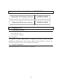
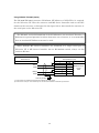
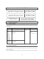
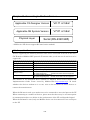
Applicable CX-Designer Version
Applicable NS System Version
V2.10 or later
V6.70 or later
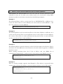
If the PT system program is old, it needs to be updated. For information on how to
update, refer to the manual "How to recover or update the PT system program Ver x.x".
(Start Menu - All Programs - OMRON - CX-One - CX-Designer)
The PT system program is bundled to CX-Designer, and is installed to
"RecoverUpdate_x_x" folder (“x_x” indicates version number) in CX-Designer's folder.
If not installed, please re-execute CX-Designer's or CX-One's setup program, and
install it.
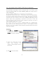
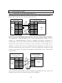
Use the following procedure to confirm the version number of CX-Designer and PT
system program.
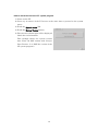
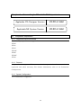
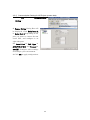
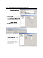
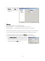
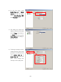
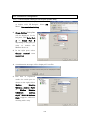
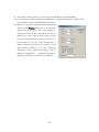
How to check the version of CX-Designer
1) Start up CX-Designer.
2) From the menu, select Help Menu
- About CX-Designer.
3) The following dialog box will be
displayed. The version is shown in
the circle.
14
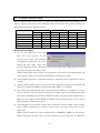
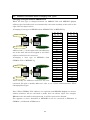
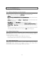
How to check the version of PT system program
1) Power on the PT.
2) Press any 2 corners of the PT screen at the same time to proceed to the system
menu.
3) Touch the Special screen Tab.
4) Touch the System Version Button.
5) The screen as shown right will be displayed.
Check the circled number.
This example shows the system version
6.60. (Note: Do NOT confuse with "Project
Data Version". It is NOT the version of the
PT system program.)
15
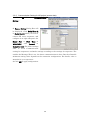
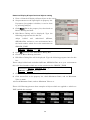
1-2
-2 Creating Screen Data
This section provides general procedures of how to create screen data, providing an
example of connecting to Mitsubishi FX Series sequencer to PORTA on a PT. Even
when connecting other PLC to PT, you can create screen data in the same way.
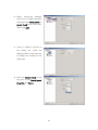
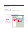
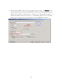
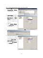
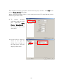
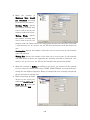
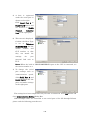
1) Start up CX-Designer and select File Menu New Project.
2) New Project Dialog Box will be displayed.
Set the System Version to a version that
supports the PLC to be connected. Any
names can be given to the Project Title
and File Name.
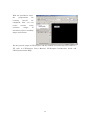
3) Press the Comm. Setting Button. Some confirmation dialog boxes may be
displayed. Check the messages and press appropriate buttons.
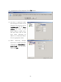
4) Comm. Setting Dialog Box will be displayed. Click SERIALA on the tree in the
left-side pane.
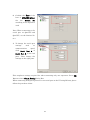
5) Set the Type to MELSEC-F on
the right screen.
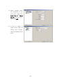
6) Check that Protocol is set to
Computer Link, and set Comm.
Speed, Data Bits, Stop Bits,
Parity and Station No. Set those
settings to the same as the
communication setting of the
FX
Series
sequencer
to
be
connected to the PT.
When you use a PLC other than Mitsubishi FX Series, necessary setting items will
be displayed in accordance with the PLC type. For details on settings, refer to each
PLC chapter.
7) Press OK Button. Some confirmation dialog boxes may be displayed. Check the
messages and press OK or Yes Button.
16
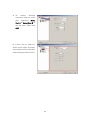
With the procedures above,
the
preparations
creating
screens
for
are
completed. Now you can
create
extensive
screens
using
ranges
of
functional objects including
lamps and buttons.
For the general usages of CX-Designer and the method of transferring screen data to a
PT, refer to CX-Designer User's Manual, CX-Designer Introduction Guide and
CX-Designer Online Help.
17
1-3
-3 Restrictions and Notes on Connecting Non-OMRON PLCs
Please read the following restrictions and notes carefully and make sure them when
you connect the host (except SYSMAC PLC) to NS-series PT. Here, only general
restrictions and notes are provided. For instructions of each host type, refer to the
chapter that describes each host type.
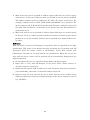
1-3-1 Notes and Restrictions When Changing Host Types
When converting host type using Comm. Setting Dialog Box, please pay attention to
the following.
1) When any addresses of the host before converting are already used, host types can
be converted only between SYSMAC PLC and other host types. Conversion
between host types (except SYSMAC PLC) is not allowed.
2) When host type being converted, addresses are automatically converted by
predetermined rule. Details of the rule are described in the chapter of each host
type.
3) When addresses being converted automatically, addresses which cannot be
mapped to new host type are not converted. This may cause invalid addresses, so
please search and modify such addresses after host conversion by the following
procedure.
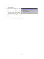
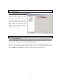
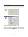
How to search and modify the invalid addresses
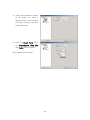
1) If Symbol Table window is not shown, press [Alt] + [2] to show it.
2) Right-click the symbols displayed area, and click Find Invalid Addresses.
3) Invalid addresses will be highlighted by light cream color. Modify all of them.
(Even if you have modified invalid addresses, highlighting is not reset until the
next step is done).
4) Do the step 2) again. If all highlightings are reset, it means modification is
completed.
N
Noottee:: Conversion of host type is allowed with
no restrictions if you do not use any addresses
of converting host. But, the dialog like right
may be displayed if you have once used some
addresses of the converting host and removed them after that. In such case, execute
Find Unused Symbols function on Symbol Table Window, then, try again.
To know for which objects the host addresses are used, select Find Menu - Address
Cross Reference.
18
1-3-2 Restrictions on Macro Functions
The following macro functions are NOT supported for any host types except SYSMAC
PLC.
・ READHOSTB
・ READHOSTW
・ WRITEHOSTB
・ WRITEHOSTW
1-3-3 Differences of Data Format in PLCs, and Restrictions Caused by Them
Data format depends on host type. For such reason, be careful when using macro
functions that read/write data from/to non-SYSMAC.
For details on each host type, refer to Data format and Notes sections in the
corresponding chapters of each.
1-3-4 Restriction on Using Functions Monitoring a Large Number of Addresses
When connecting to a host except SYSMAC PLC, functions which monitor large
number of addresses ―Data Log, Alarm/Event, and so on― may slow responses.
Moreover, monitoring inconsecutive addresses may make it worse. This is caused by a
performance limitation of communicating with the host. Therefore, when using these
functions, please minimize the number of monitoring addresses, and design the system
to be able to monitor consecutive addresses as possible as you can.
1-3-5 Notes for Using RS-232C of NSH-series PTs
Use the cable NSH 5-232UL-[]M for connecting NSH-series PT and any type of host
except SYSMAC PLC. If NSH 5-232CW-[]M is used, an NSH-Series PT cannot
communicate with the host which uses RS/CS signals.
1-3-6 Notes for Using Function Switches of NSH-series PTs
Function Switches of NSH-series PT whose status is notified to the host by
communication is supported by ONLY SYSMAC PLCs.
Any type of host described on
this manual does NOT support these function switches.
Hard-wired function switches are supported any type of hosts.
1-3-7 System Memory Compatibility with the NT Series
This function will not work when connected to a PLC that is not manufactured by
OMRON.
1-3-8 Restriction on Using Functions Connecting Except for a Serial Port Where a
Communication Error Occurs
This function will not work when connected to a PLC that is not manufactured by
OMRON.Please select No in the Comm. Setting Dialog Box.
19
Chapter 2
Connecting to Mitsubishi A sequencers
Applicable CX-Designer Version
V2.00 or later
Applicable NS System Version
V6.60 or later
2-1 Compatible sequencers
2-1-1 Supported Sequencer Models
The following sets of sequencer and computer link unit are supported.
A1SHCPU
+ A1SJ71UC24-R□ or A1SJ71UC24-PRF
A2USCPU
+ A1SJ71UC24-R□ or A1SJ71UC24-PRF
A2USHCPU-S1 + A1SJ71UC24-R□ or A1SJ71UC24-PRF
A2ACPU
+ AJ71UC24
2-1-2 Protocol
Computer Link is supported.
2-1-3 System Configuration
1 to 1 connection is supported.
20
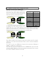
2-2 Connection configuration
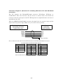
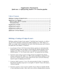
2-2-1 Overview of Connection Method
Connect NS-Series PT to Mitsubishi A Series as illustrated below. Make cable
according to the connection diagram. For detailed information of cables, please refer to
2-3 Communication Cables.
2-2-2 Communication Setting for Sequencers
Make the following communication settings with a sequencer. For the setting methods,
refer to your programming tool's or your sequencer's manual.
Protocol:
Dedicated protocol (Form 1)
Data bit:
Set the same as for the communication setting's Data Bits of
the PT.
Parity:
Set the same as for the communication setting's Parity of the
PT.
Stop bit:
Set the same as for the communication setting's Stop Bits of
the PT.
Transmission speed:
Set the same as for the communication setting's Comm.
Speed of the PT.
Sumcheck:
YES (ON)
Station number setting:
Set the same as for the communication setting's Station No.
of the PT.
21
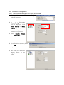
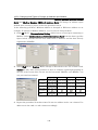
2-2-3 Communication Setting for NS project (screen data)
1) Click PT Menu - Communication Setting
2) Comm. Setting Dialog Box
will be displayed. Click Serial
Port A or Serial Port B which
you want to connect A series
sequencer, and configure it in
right-side pane.
Set Serial Port to PLC, Type
to MELSEC-A, and Protocol
to
Computer
Link.
The
smaller the Message Wait, the faster the communications. However, the allowable
minimum value depends on the connection configuration. For details, refer to
manuals for the sequencer computer link. For details on other setting items, refer
to 2-2-2 Communication setting for sequencers and make settings depending on
sequencer settings.
3) Click OK to apply configuration.
22
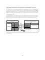
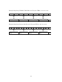
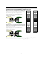
2-3 Communication Cables
2-3-1 For NS-series PTs Excluding NSH-series PTs
Using 9-pin RS-232C interface on the computer link unit
Make cable according to the connection diagram below. Bold line with an asterisk mark
('*') can be omitted when the computer link unit is configured not to check CD signal.
Mitsubishi A series Computer Link Unit
(RS-232C, 9pin)
PT Serial Port
(excluding NSH)
Connector
D-Sub
9 pin
Male
Signal
Pin No.
FG
1
*
Pin No.
Signal
1
CD
RD
SD
2
2
RD
3
3
SD
RS
4
4
DTR
CS
5
5
SG
+5V
6
6
DSR
7
7
RS
8
8
CS
9
9
SG
Shield
Hood
Connector
D-Sub
9 pin
Male
Hood
Using RS-422/485 interface on the computer link unit
To communicate using RS-422/485 type of Computer Link unit, the PT requires an
RS-232C/RS-422A Converter (OMRON NS-AL002, NT-AL001 or CJ1W-CIF11).
Applicable cable is as illustrated below.
Connect cable to the Converter, and then mount it on a serial port of the NS (Be sure to
complete the connection before mounting the Converter on the PT).
Set the DIP switch of NS-AL002 to 4-wire and enable terminator if necessary (see also
NS-AL002's instruction sheet).
RS-232C/RS-422A Converter
model NS-AL002
Connector
RS-422A
Terminal block
Signal
Mitsubishi A Series Computer Link Unit
( RS-422)
No.
FG
1
Signal
RDB(+)
2
RDA(+)
SDB(+)
3
RDB(-)
RSB(+)
4
SDA(+)
5
SDB(-)
RDA(-)
6
SG
SDA(-)
7
RSA(-)
8
Connector
Terminal block
FG
Shield
* Connect to FG which is clas s D grounded.
Note: If NS cannot be grounded for some reason, shield wire also needs to be connected
to FG of NS-AL002.
23
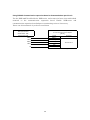
2-3-2 For NSH-series PTs
Using 9-pin RS-232C interface on the computer link unit
Use the NSH 5-232UL-[]M cable for NSH-series, and connect its D-Sub connector to
the computer link unit using the cable below.
Loopback connecters are mounted on the CN7 and CN8 connecters of the NSH cable.
Remove the connecters and connect the CN7 and CN8.
NSH special cable
(NSH5-232UL-[]M)
Connector
D-Sub
9 pin
Female
Mitsubishi A series Computer Link Unit
(RS-232C, 9pin)
Signal
Pin No.
FG
1
Pin No.
Signal
1
CD
RD
SD
2
2
RD
3
3
SD
CS
4
4
DTR
RS
5
5
SG
+5V
Screw
m m , Fem ale
SG
*
6
6
DSR
7
7
RS
8
8
CS
9
9
Hood
Shield
Connector
D-Sub
9 pin
Male
Hood
Using RS-422/485 interface on the computer link unit
Use the NSH 5-422UL-10M cable for NSH-series, and wire as follows. Enable
NSH-series and computer link unit's terminating resistor if necessary.
NSH Special Cable
( NSH5-422UL-10M )
Mitsubishi A Series Computer Link Unit
( RS-422)
Forked loose wires
Signal
SDB(+)
Connector
RDA(+)
SDA(-)
RDB(-)
RDB(+)
SDA(+)
RDA(-)
SDB(-)
Terminal block
SG
FG
FG*
* Connect to FG which is clas s D grounded.
24
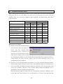
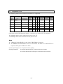
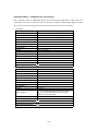
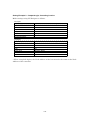
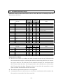
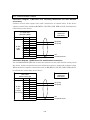
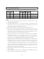
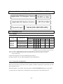
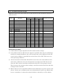
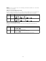
2-4 Accessible Address Range
Screen data can access the following addresses of A series sequencer. The devices with
YES in the table can be accessed with all range of devices' numbers that your
sequencer supports. Read carefully the restrictions and notes below the table.
Bit Access
Word Access
Read
Write
Read
Write
Restrictions and Notes
X
Input
YES
YES
YES
YES
1) 2) 3) 5)
Y
YES
YES
YES
YES
1) 2) 3) 5)
M
Output
Auxiliary
Relay
YES
YES
YES
YES
1) 2) 3) 4) 5) 7)
L
Latch relay
YES
YES
YES
YES
1) 2) 3) 4) 5)
S
Step relay
YES
YES
YES
YES
1) 2) 3) 4) 5)
Device
B
Link relay
YES
YES
YES
YES
1) 2) 3) 5)
F
Annunciator
YES
YES
YES
YES
1) 2) 3) 5)
TU
Timer contact
No
No
YES
YES
1) 2) 3) 9)
TC
No
No
YES
YES
1) 2) 3)
CU
Timer coil
Counter
contact
No
No
YES
YES
1) 2) 3) 9)
CC
Counter coil
No
No
YES
YES
1) 2) 3)
D
Data register
YES
YES
YES
YES
1) 2) 3) 6)
W
Link register
YES
YES
YES
YES
1) 2) 3) 6)
R
File register
Extension file
register
YES
YES
YES
YES
1) 2) 3) 6)
YES
YES
YES
YES
1) 2) 3) 6) 10)
T
Timer
YES
YES
No
No
1) 2) 3) 8)
C
Counter
YES
YES
No
No
1) 2) 3) 8)
xxR
Restrictions and Notes
1) If "writing operation during run" is disabled, any writing operations are rejected
regardless of the table above during the sequencer running.
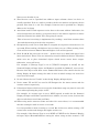
2) Do not use the device numbers
that your sequencer does not
support.
contains
If
screen
data
unsupported
that
device
numbers are operated, an error
dialog box like right will be displayed (error code may be different). When you use
objects that occupy large size of memory (such as string display & input objects),
please pay an extra attention not to use unsupported device numbers.
3) Avoid a situation in which both PT and sequencer write data to the same address.
Otherwise, the value changes that are made by a sequencer may be lost when a
25
sequencer rewrites word that contains bits which PT is also going to rewrite.
This is because bit writing for word devices is implemented by reading 1 word that
contains those bits and then writing it back to the sequencer.
4) M, L, and S share same area and any device number of M, L and S can be accessed
with any device name of M, L and S. However, please avoid accessing same
address with different notation, because it makes communication slower.
5) Bit device can be specified where word device is usually specified (except for Timer
contact and Counter contact). In this case, only addresses that are divisible by 16
can be specified, and address number must be suffixed by 'W', which means word
access. For example, addresses such as X0W, Y10W, S16W and M224W can be
specified for Numeral Display & Inputs object.
Make sure that device numbers of X, Y, and B are noted by hexadecimal. Therefore,
addresses such as X0, X10, X20, X30 and X100 etc. are divisible by 16. Please note
that X16 and X32 are not divisible by 16.
6) Word devices can be specified into address input columns where bit device is
usually specified. To do so, suffix a period to the device number and specify the bit
position (0 to 15) after that. For example, D123.12 can be specified for a display
address of a bit lamp.
7) Even M8992 to 8999 and M9256 to 9263 do not exist, word access from M8992 and
M9248 are exceptionally accepted. When reading, not existing addresses are
always 0. When writing, they are ignored.
8) Do not allocate devices T and C to the String Display & Input object.
9) When specifying "Timer contact" or "Counter contact" on CX-Designer, use "TU" or
"CU" as a device name.
10) Expansion file register (00R to 64R) can be used. To specify device numbers of
them, write "R<block #>_<device #>" (e.g. "R04_00012").
26
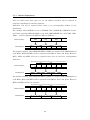
2-5 Data Format
2-5-1 Numerals
NS treats the numeric data stored in A sequencer as little-endianed.
For example, when 16bit integer
Address
D0
value 0x1234 is written into D0 from
Bit
0
1
2
3
4
5
6
7
8
9 10 11 12 13 14 15
NS, sequencer's memory becomes
Value
0
0
1
0
1
1
0
0
0
1
Value(hex)
0
0
1
0
0
0
0x1234
like right.
Another example, 32bit integer value 0x12345678 is written, sequencer's memory
becomes like below.
Address
D0
D1
Bit
0
1
2
3
4
5
6
7
8
9 10 11 12 13 14 15 0
1
2
3
4
5
6
7
8
9 10 11 12 13 14 15
Value
0
0
0
1
1
1
1
0
0
1
0
1
0
1
1
0
0
0
1
Value(hex)
1
0
1
0
1
0
0
0x5678
0
0
1
0
0
0
0x1234
Even when NS accesses bit devices as a word device, the rule is as same as above.
For example, when the status of M
device is like right, M0W becomes
0x1234.
Device
M
Bit
0
1
2
3
4
5
6
7
8
9 10 11 12 13 14 15
Value
0
0
1
0
1
1
0
0
0
1
Value(hex)
0
0
1
0
0
0
0x1234
2-5-2 Strings
ASCII String
For example, when an ASCII string
Address
D0
D1
D2
D3
"ABCDEF" is written from NS, sequencer's
Value(char)
"AB"
"CD"
"EF"
NULL NULL
Value(hex)
0x4241
0x4443
0x4645
0x0000
memory becomes like right.
Please make sure that NS handles string data by 1 word. So when the length of the
string is even, two bytes of null characters will be appended.
Unicode String
For example, when a Unicode string "ABCDEF" is written from NS, sequencer's
memory becomes like below.
Address
D0
D1
D2
D3
D4
D5
D6
Value(char)
A
B
C
D
E
F
NULL
Value(hex)
0x0041
0x0042
0x0043
0x0044
0x0045
0x0046
0x0000
27
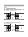
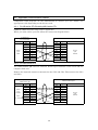
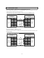
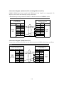
2-6 Address Conversion When Changing Host Types
Changing host types between OMRON PLCs
When host type is changed between SYSMAC PLC and A series PLC, address types
(areas / devices) are automatically changed according to the table shown right (see the
figure below).
SERIALA:HR00000.7
SERIALA:DM00123
SERIALA:L00007
SERIALA:D00123
"―" in the right table means those addresses
SYSMAC PLC
CS, CJ, etc…
MELSEC-A
A Series sequencer
CIO
M
HR
L
AR
―
LR
B
TIM
T
CNT
C
DM
D
WR
W
EM
―
EM0~EMC
―
will not be changed. This may cause invalid
TU
TU
CU
CU
addresses (see the figure below), so you have to
―
X
modify such invalid addresses by yourself. Refer
―
Y
―
F
to 1-3-1 Notes and Restrictions When Changing
―
S
Host Type for how to find and modify them.
―
R
―
xxR
cannot be mapped to new PLC's address, so they
SERIALA:AR00000.7
SERIALA:EM00123
SERIALA:AR00000.7
―
TC
―
CC
SERIALA:EM00123
N
Noottee:: Address numbers will be changed to make their bit offsets equal. For example,
HR00003.12 is the 60th bit (60=16×3+12), so will be converted to L00060.
The opposite is same. L00080W of MELSEC-A will be changed to HR00005 of SYSMAC,
and L00084 to HR00005.4.
28
2-7 Precautions
See also instructions shown in 2-4 Accessible Address Range.
2-7-1 Macro functions
Precaution for Macro function (READCMEM/WRITECMEM)
Data length that can be read/written at once with READCMEM/WRITECMEM
depends on your sequencer and computer link unit. Please see Mitsubishi's manuals
that describe details of computer link. The limitation will be written as "Number of
points processed in one-time update" in those manuals.
If too large data length is specified, a macro error will occur.
Precaution when handling ASCII string with macro function
Because of the difference of ASCII string format between NS and A series sequencer,
byte-order must be changed after reading ASCII string by READCMEM and before
writing by WRITECMEM. Otherwise, strange strings will be seen on NS or A.
When reading 64 bytes length of ASCII string from sequencer's D0 to NS's $W1000,
program as follows (adapt mitsubishi_a_hostname to your environment).
READCMEM($W1000,[mitsubishi_a_hostname:D00000],32);
SWAP($W1000,32);
N
Noottee:: Some models of sequencer rejects 32 words reading command. In such a case,
please divide 32 words into some pieces, and execute READCMEM some times.
When writing 64 bytes length of ASCII string from NS's $W1000 to FX's D0, program
as follows (adapt mitsubishi_a_hostname to your environment). The program below
first changes the byte-order to sequencer's format, then writes it to sequencer, and
finally re-changes to NS-format.
SWAP($W1000,32);
WRITECMEM([mitsubishi_a_hostname:D00000],$W1000,32);
SWAP($W1000,32);
N
Noottee:: Some models of sequencer rejects 32 words writing command. In such a case,
please divide 32 words into some pieces, and execute WRITECMEM some times.
29
Chapter 3
Connecting to Mitsubishi FX Sequencers
Applicable CX-Designer Version
V2.00 or later
Applicable NS System Version
V6.60 or later
3-1 Compatible Sequencers
3-1-1 Supported Sequencer Models
The following sequencers are supported.
-FX0N
-FX1S
-FX1N
-FX1NC
-FX2N
-FX3UC
-FX3G
3-1-2 Protocol
Computer Link is supported. Use a communication expansion board or communication
expansion unit when necessary. For further information, refer to 3-2 Connection
Configuration.
3-1-3 System Configuration
1 to 1 connection is supported.
30
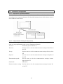
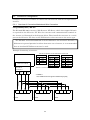
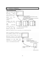
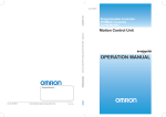
3-2 Connection Configuration
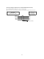
3-2-1 Overview of Connection Method
Connect NS-series PT to Mitsubishi FX Series as illustrated below. Use a
recommended model of cable or make cable according to the connection diagram. For
detailed information of cables, please refer to 3-3 Communication Cables.
NS series PT
Communication Expansion Board
or Communication Expansion Unit
RS-232C Port
PORT A or PORT
Cable (converter may be required
in some cases)
Mitsubishi FX series
CPU unit
3-2-2 Communication Setting for Sequencers
Make the following communication settings with a sequencer. For the setting methods,
refer to your programming tool's or your sequencer's manual.
Protocol:
Dedicated protocol (Computer Link)
Data length:
Set the same as for the communication setting's
Data Bits of the PT.
Parity:
Set the same as for the communication setting's
Parity of the PT.
Stop bit:
Set the same as for the communication setting's
Stop Bits of the PT.
Transmission speed:
Set the same as for the communication setting's
Comm. Speed of the PT.
Sumcheck:
ON (YES)
Transmission control procedure:
Form1 (without CR, LF)
Station number setting:
Set the same as for the communication setting's
Station No. of the PT.
31
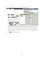
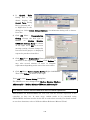
3-2-3 Communication Setting for NS project (screen data)
1)
Click
PT
Menu
-
Communication
Setting….
2) Comm. Setting Dialog Box will
be displayed. Click Serial Port A
or Serial Port B which you want to
connect FX series sequencer, and
configure it on right-side pane. Set
Serial Port to PLC, Type to
MELSEC-F,
and
Protocol
to
Computer Link. For other settings,
refer
to
3-2-2
Communication
setting for sequencers and make settings according to the settings for sequencer. The
smaller the Message Wait is set, the faster communications is done. But the allowable
minimum setting value depends on the connection configuration. For details, refer to
manuals for your sequencer.
3) Click OK to apply configuration.
32
3-3 Communication Cables
An applicable communication cable depends on the communication method of Serial
communication expansion board and the adapter. Prepare a cable applicable to your
configuration.
3-3-1 For NS-series PTs Excluding NSH-series PTs
Using 9-pin RS-232C Communication expansion board (FX[][]-232-BD) or 9-pin
RS-232C Communication special adapter (FX3U-232-ADP, FX2NC-232ADP)
Make cable according to the connection diagram below.
FX series Communication expansion board
or Communication special unit
PT Serial Port
(f or excluding NSH)
Connector
D-Sub
9 pin
Male
Signal
Pin No.
Pin No.
Signal
FG
1
1
CD
SD
2
2
RD
RD
3
3
SD
RS
4
4
ER
CS
5
5
SG
+5V
6
6
DR
7
7
8
8
SG
9
Hood
Shield
Connector
D-Sub
9 pin
Female
9
Hood
OMRON XW2Z-S002 (2m long) cable is also applicable. Even cable connection of
XW2Z-S002 is not same as the connection diagram above, it is applicable because both
NS and FX do not check control signals.
Using 25-pin RS-232C Communication special adapter (FX0N-232-ADP)
Follow the connection diagram below.
FX series Communication special adapter
( 25 pin type)
PT Serial Port
(f or excluding NSH)
Connector
D-Sub
9 pin
Male
Signal
Pin No.
Pin No.
Signal
FG
1
1
FG
SD
2
2
SD
RD
3
3
RD
RS
4
4
RS
CS
5
5
CS
6
6
DR
7
7
SG
+5V
8
SG
9
Hood
Shield
33
20
ER
Hood
Connector
D-Sub
25 pin
Male
Using RS-485 Communication expansion board or Communication special unit
To communicate using RS-485 Communication expansion board or Communication
special unit on a sequencer, the PT requires an RS-232C/RS-422A Converter (OMRON
NS-AL002). Applicable cable is as illustrated below. Connect cable to NS-AL002, then
mount it on a serial port of the NS (Be sure to complete the connection before mounting
a NS-AL002 on a PT).
Set the DIP switch of NS-AL002 to 4-wire and enable terminator if necessary (see also
NS-AL002's instruction sheet). Enable the terminating resistance on the NS-AL002
when necessary. (To enable the terminating resistance, turn ON the DIP switch 4.)
RS-232C/RS-422A Converter
model NS-AL002
Connector
RS-422A
Terminal block
Signal
FX series Communication expansion board
or Communication special adapter
( RS-485)
No.
FG
1
Signal
RDB(+)
2
RDA(+)
SDB(+)
3
RDB(-)
RSB(+)
4
SDA(+)
5
SDB(-)
RDA(-)
6
SG
SDA(-)
7
RSA(-)
8
Shield
Connector
Terminal block
Class-D grounding
If NS cannot be grounded for some reason, shield wire also needs to be connected to FG
of NS-AL002.
34
3-3-2 For NSH-series PTs
Using 9-pin RS-232C Communication expansion board (FX[][]-232-BD) or 9 pin
RS-232C Communication special adapter (FX3U-232-ADP, FX2NC-232ADP)
Use the NSH 5-232UL-[]M cable for NSH-series, and connect its D-Sub connector to
the computer link unit using the cable below.
NSH special cable
(NSH5-232UL-[]M)
Connector
D-Sub
9 pin
Female
FX series Communication expansion board
or Communication special unit
Signal
Pin No.
Pin No.
Signal
FG
1
1
CD
RD
2
2
RD
SD
3
3
SD
CS
4
4
ER
RS
5
5
SG
6
6
DR
7
7
+5V
Screw
m m , Fem ale
SG
8
8
9
9
Hood
Shield
Connector
D-Sub
9 pin
Female
Hood
Using 25-pin RS-232C Communication special adapter (FX0N-232-ADP)
Use the NSH 5-232UL-[]M cable for NSH-series, and connect its D-Sub connector to
the computer link unit using the cable below.
NSH special cable
(NSH5-232UL-[]M)
Connector
D-Sub
9 pin
Female
FX series Communication special adapter
( 25 pin type)
Signal
Pin No.
Pin No.
Signal
FG
1
1
FG
RD
2
2
SD
SD
3
3
RD
CS
4
4
RS
RS
5
5
CS
6
6
DR
7
7
SG
+5V
Screw
m m , Fem ale
8
SG
9
Hood
Shield
35
20
ER
Hood
Connector
D-Sub
25 pin
Male
Using RS-485 Communication expansion board or Communication special unit
Use the NSH 422UL-10M cable for NSH-series, and connect its loose wires with forked
terminal
to
the
communication
expansion
board.
Enable
NSH-series
and
communication expansion board/adapter's terminating resistor if necessary.
Please cut fork terminals if you do not need them.
FX series Communication expansion board
or Communication special adapter
( RS-485)
NSH Special Cable
( NSH5-422UL-10M )
Forked loose wires
Signal
SDB(+)
Connector
RDA(+)
SDA(-)
RDB(-)
RDB(+)
SDA(+)
RDA(-)
SDB(-)
Terminal block
SG
FG
FG*
* Connect to FG which is class D grounded.
36
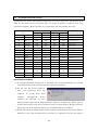
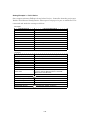
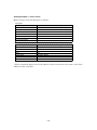
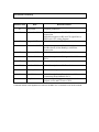
3-4 Accessible Address Range
When Mitsubishi FX Series is used as a host, screen data can access the following
addresses. The devices with YES in the table can be accessed with all range of devices'
numbers that your sequencer supports. Read carefully the Restrictions and Notes
below the table.
Word Access
Device
D
1)
6)
M
6)
T (Timer current value)
TU (Timer contact)
Read
Write
YES
YES
YES
7)
8)
C (Counter current value)
CU (Counter contact)
7) 9) 10)
8)
Bit Access
2)
YES
2)
YES
YES
No
No
YES
YES
No
No
Read
YES
3) 4)
Write
YES
3) 4)
YES
YES
No
No
YES
YES
No
No
YES
YES
X
YES
2)
YES
2)
YES
YES
Y
YES
2)
YES
2)
YES
YES
2) 5)
YES
YES
S
YES
R
2) 5)
YES
YES
YES
YES
3) 4)
YES
3) 4)
Restrictions and Notes
1) Do not use the device numbers that
your sequencer does not support. If
screen data that contain those
unsupported device numbers are
operated, an error dialog box to the
right will be displayed (error code
may be different). When you use objects that occupy large size of memory (such as
string display & input objects), please pay an extra attention not to use
unsupported device numbers.
2) Bit device can be specified where word device is usually specified (Except for Timer
contact and Counter contact). In this case, only addresses that are divisible by 16
can be specified, and address number must be suffixed by 'W', which means word
access. For example, addresses such as X0W, Y20W, S16W and M224W can be
specified for Numeral Display & Inputs object.
Note that device numbers of X and Y are octal notation. Therefore addresses such
as X0, X20, X40, X60 and X100 etc. are divisible by 16. Please note that X16 and
37
X32 are not divisible by 16.
3) Word devices can be specified into address input columns where bit device is
usually specified. To do so, suffix a period to the device number and specify the bit
position after that (0 to 15). For example, D123.12 can be specified for a display
address of a bit lamp.
4) Avoid that both PT and sequencer write data to the same address. Otherwise, the
value changes that are made by a sequencer may be lost when a sequencer rewrites
word that contains bits which PT is also going to rewrite.
This is because bit writing is implemented by reading 1 word that contains those
bits and then writing it back to the sequencer.
5) Exceptionally, word access from S992 is accepted for sequencer whose device S is
up to 999. When reading, the higher 8 bits are always set to 0. When writing, lower
8 bits will be written to S992 to 999 and higher 8 bits will be ignored.
6) Each D and M has two types of areas ― normal area (0 to 7999) and special area
(8000 and above). These areas are internally treated as different devices. Therefore,
make sure not to place functional objects which access across these ranges.
Otherwise, errors will occur.
For example, if [Storage Type] is set to [UDINT (unsigned, 2 words)] for the
Numeral Display & Input object and D7999 is specified for [Address], error occurs.
Because this object reads data across D7999 and D8000. Also ensure that for the
String Display & Input setting, the ends of areas in which strings are stored are
not across the ranges.
7) Do not allocate devices T and C to the String Display & Input object.
8) Device name TU and CU are used in CX-Designer for the timer contact and the
counter contact respectively.
9) If functional objects which access across the C199-C200 range are placed, error will
occur when operating the project on PT.
For example, if a storage type is set to DINT (signed, 2 words) for the Numeral
Display & Input and C199 is specified for an address, an error occurs, because this
object reads data across C199 and C200.
10) When using 32 bit counters (C200 and above) for screen data, it is recommended
that the setting be made to access as 2 words.
It is also possible to make a setting as 1 word. But in this case, when writing, a PT
writes lower 16 bits and changes the higher 16 bits to 0.
For example, if the Storage Type is set to DINT or UDINT for the Numeral Display
& Input object (Recommendation setting for when using 32 bits counter) a PT
38
accesses a sequencer as 2 words. Note that if the Storage Type is set to INT or
UINT, not only higher 16 bits are ignored but also they are set to 0 when written.
39
3-5 Data Format
3-5-1 Numerals
The NS-series PT treats the numeric data stored in FX sequencer as little-endianed.
For example, when 16bit integer value 0x1234 is written into D0 from NS, sequencer's
memory becomes like right.
Another
value
Address
example,
32bit
integer
0x12345678
is
written,
D0
Bit
0
1
2
3
4
5
6
7
8
9 10 11 12 13 14 15
Value
0
0
1
0
1
1
0
0
0
1
Value(hex)
0
0
1
0
0
0
0x1234
sequencer's memory becomes like below.
Address
D0
D1
Bit
0
1
2
3
4
5
6
7
8
9 10 11 12 13 14 15 0
1
2
3
4
5
6
7
8
9 10 11 12 13 14 15
Value
0
0
0
1
1
1
1
0
0
1
0
1
0
1
1
0
0
0
1
Value(hex)
1
0
0
1
0
0
0x5678
0
0
1
0
0
0
0x1234
Even when NS accesses bit devices
as a word device, the rule is as same
as above.
1
For example, when the
Device
M
Bit
0
1
2
3
4
5
6
7
8
9 10 11 12 13 14 15
Value
0
0
1
0
1
1
0
0
0
1
Value(hex)
0
0
1
0
0
0
0x1234
status of M device is like above,
M0W becomes 0x1234.
3-5-2 Strings
ASCII String
For example, when an ASCII string
"ABCDEF" is written from NS, sequencer's
memory becomes like right.
Address
D0
D1
D2
D3
Value(char)
"AB"
"CD"
"EF"
NULL NULL
Value(hex)
0x4241
0x4443
0x4645
0x0000
Please make sure that NS handles string data by 1 word. So when the length of the
string is even, two byte of null characters will be appended.
Unicode String
For example, when a Unicode string "ABCDEF" is written from NS, sequencer's
memory becomes like below.
Address
D0
D1
D2
D3
D4
D5
D6
Value(char)
A
B
C
D
E
F
NULL
Value(hex)
0x0041
0x0042
0x0043
0x0044
0x0045
0x0046
0x0000
40
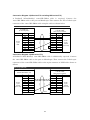
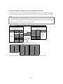
3-6 Address Conversion When Changing Host Types
Changing host types between OMRON PLCs
When host type is changed between SYSMAC
PLC and FX series PLC, address types (areas /
devices) are automatically changed according to
the table shown right (see the figure below).
SERIALA:AR00000.7
SERIALA:DM00123
SERIALA:S00007
SERIALA:D00123
SYSMAC PLC
CS, CJ, etc…
MELSEC-F
FX Series sequencer
CIO
M
HR
―
AR
S
LR
―
TIM
T
CNT
C
DM
D
WR
―
EM
―
EM0~EMC
―
TU
TU
CU
CU
―
X
―
Y
―
R
"―" in the right table means those addresses cannot be mapped to new PLC's address,
and they are not changed. This may cause invalid addresses (see the figure below), so
please modify such invalid addresses by yourself. Refer to 1-3-1 Notes and Restrictions
When Changing Host Type for how to find and modify them.
SERIALA:HR00000.7
SERIALA:HR00000.7
SERIALA:EM00123
SERIALA:EM00123
Note: Address numbers will be changed to make their bit offsets equal. For example,
AR00003.12 is the 60th bit (60=16×3+12), so will be changed to AR00005 of SYSMAC,
and S00084 to AR00005.4.
41
3-7 Precautions
See also instructions shown in "3-4
Accessible Address Range".
3-7-1 Macro Functions
Precaution for Macro function (READCMEM/WRITECMEM)
Data length that can be read/written at once with READCMEM/WRITECMEM is
limited to the limitation of computer-link specification. It depends on model of
sequencer, so please see Mitsubishi's manuals that describe details of computer-Link.
The limitation will be written as "Number of points processed in one-time update" in
those manual.
If too large data length is specified, a macro error will occur.
Precaution when handling ASCII string with macro function
Because of the difference of ASCII string format between NS and FX series sequencer,
byte-order must be changed after reading ASCII string by READCMEM and before
writing by WRITECMEM. Otherwise, strange strings will be seen on NS or FX.
When reading 64 bytes length of ASCII string from FX's D0 to NS's $W1000, program
as follows (adapt fx_hostname to your environment).
Note: Some models of sequencer rejects 32 words reading command. In such a case,
please divide 32 words into some pieces, and execute READCMEM some times.
READCMEM($W1000,[fx_hostname:D00000],32);
SWAP($W1000,32);
When writing 64 bytes length of ASCII string from NS's $W1000 to FX's D0, program
as follows (adapt fx_hostname to your environment). The program below first changes
the byte-order to FX-format, then writes it to FX, and finally re-changes to NS-format.
SWAP($W1000,32);
WRITECMEM([fx_hostname:D00000],$W1000,32);
SWAP($W1000,32);
Note: Some models of sequencer rejects 32 words writing command. In such a case,
please divide 32 words into some pieces, and execute WRITECMEM some times.
42
Chapter 4
Connecting to Siemens S7-300 PLCs
Applicable CX-Designer Version
V2.00 or later
Applicable NS System Version
V6.60 or later
4-1 Compatible PLCs
4-1-1 Supported PLC Models
The following PLC models are supported.
・ S7-300 CPU315-2 DP
・ S7-300 CPU317-2 PN/DP
4-1-2 Protocol
The 3964(R) + Prodave HMI protocol is supported. In order to connect, Siemens
SIMATIC S7 HMI Adapter (order number: 6ES7 972-0CA11-0XA0) is required. For
detailed information refer to 4-2 Connection Configuration.
4-1-3 System Configuration
At the moment only a 1 to 1 connection is supported.
43
4-2 Connection Configuration
4-2-1 Overview of Connection Method
Connect a PT to Siemens S7-300 series in the following methods. A Siemens SIMATIC
S7 HMI Adapter (6ES7 972-0CA11-0XA0) or Renu Gateway MPI Adapter is required.
Use a recommended model of cable or make it yourself according to the connection
diagram. For details on cables refer to 4-3 Applicable Communication Cables.
NS series PT
SIMATIC S7 HMI Adapter
Cable
Siemens S7-300 Series
PLC
Serial Port
PORT A or PORT B
4-2-2 Communication Settings for PLCs
Make the following communication settings to connect to the PLC. For more
information on how to setup the communication of the S7 PLC, refer to manuals for
your programming tool or PLC.
MPI Transmission speed: Set to 187.5 kbps
44
4-2-3 Communication Setting for NS Project (screen data)
1) Click
PT
Menu
-
Communication
Setting….
2) Comm. Setting Dialog Box will
be displayed. Click Serial Port A
or Serial Port B depending on the
port you want to connect S7-300
series PLC, and configure it on
right-side pane.
Set Serial Port to PLC, Type to
SIMATIC S7-300, and Protocol to
3964(R). Configure other settings
according to your environment.
3) Click OK to apply configuration.
45
4-3 Applicable Communication Cables
Compatible cable depends on the combination of devices you use. Please use
appropriate cable depending on the devices used.
4-3-1 For NS-series PTs Excluding NSH-series PTs
OMRON XW2Z-S002 (2m long) cable is applicable.
When you make cables yourself, follow the connection diagram below.
PT Serial Port
SIMATIC HMI Adapter
(f or excluding NSH)
Connector
D-Sub
9 pin
Male
Signal
Pin No.
Signal
Pin No.
FG
1
CD
1
SD
2
RD
2
RD
3
SD
3
RS
4
ER
4
CS
5
SG
5
+5V
SG
6
DR
6
7
RS
7
8
CS
8
9
RI
Hood
Shield
Connector
D-Sub
9 pin
Female
9
Hood
4-3-2 For NSH-series PTs
Use NSH5-232UL-[]M and wire between D-Sub 9-pin connecter on the cable and the
computer link unit.
Remove the loopback connecters mounted on the CN7 and CN8. Then connect the CN7
and CN8.
NSH special cable
(NSH5-232UL-[]M)
Connector
D-Sub
9 pin
Female
SIMATIC HMI Adapter
Signal
Pin No.
Signal
Pin No.
FG
1
CD
1
RD
2
RD
2
SD
3
SD
3
CS
4
ER
4
RS
5
SG
5
+5V
6
DR
6
7
RS
7
8
CS
8
9
RI
9
Screw
m m , Fem ale
SG
Hood
Shield
46
Hood
Connector
D-Sub
9 pin
Female
4-4 Accessible Address Range
When using Siemens S7-300 series as a host, accessible addresses in screen data are as
follows. Devices with Yes in the following table can be used. Also read carefully the
Restrictions and Notes below the table.
Address area name 1)
Double word access
(E, A, Z are German notation)
Write
Word access
Read
3)
Bit access
Write
Read
Write
No
5)
YES
No 5)
5)
YES
No 5)
No
5)
YES
No
5)
YES
No
M
YES
YES
YES
YES
YES
YES
DB 8)
YES
YES
YES
YES
YES
YES
6)
No
No
No
No
I (E)
2)
Read
3 4))
Q (A)
2)
YES
YES
T (Present value)
No
No
YES
YES
C (Z) 2) (Present value)
No
No
YES
YES 7)
Restrictions and Notes
1) Do not use addresses that your
PLC does not support. If you
operate screen data that contains
unsupported addresses, the error
dialog box like right (error code
may be different) will be displayed, and it may also cause disturbances such as
accessing unexpected memory area.
When using objects that occupy a large memory area such as the string display &
input objects, make sure that the end address is within the range.
2) Only English notation is supported. Germany notation will be supported in future
version.
3) Siemens PLC supports byte access, but PT does not. But accessing 1 word from odd
address is supported (address specification like "MW1" is accepted).
4) Even when accessing double word, specify W (word width) as an alphabet of access
unit to add the end of the address range. For example, when accessing double word
that starts with M0 in the Numeral Display & Input, specify 2 words width such as
MW0 for the Address and UDINT and DINT for the Storage Type. Do not use D
that stands for double word access.
5) I(E) and Q(A) are read-only. Do not place functional objects which write to these
areas. When attempting to write to these areas, an error dialog box will be
displayed.
When using T, make sure that invalid values as SIMATIC_TIME are not written.
When writing an invalid value, an error dialog box (error code may be different)
47
will be displayed.
6) When using C, make sure that
invalid values as COUNTER type
cannot be written. When writing
an invalid value, an error dialog
like right (error code may be
different) will be displayed.
7) Do not use nonexistent data block numbers.
48
4-5 Data Format
4-5-1 Numerals
I, Q, M, DB area
The PT treats the numeric data stored in S7-300 PLC as big-endianed.
For example, when 16bit integer
value 0x1234 is written into MW0
from NS, PLC's memory becomes
Address
Bit
7
6
5
M0
4 3
2
1
0
7
6
5
M1
4 3
2
1
0
Value
0
0
0
1
0
1
0
0
0
1
1
1
0
0
Value(hex)
0
0x12
0
0x34
like right.
Another example, 32bit integer value 0x12345678 is written, PLC's memory becomes
like below.
Address
Bit
7
6
5
M0
4 3
2
1
0
7
6
5
M1
4 3
2
1
0
7
6
5
M2
4 3
2
1
0
7
6
5
4
3
2
1
0
Value
0
0
0
1
0
1
0
0
0
1
1
1
0
0
0
1
0
1
1
1
0
0
1
1
1
1
0
0
0
Value(hex)
0
0x12
0
0x34
0
M3
0x56
0x78
T area
Data format of T is pursuant to SIMATIC_TIME type format.
C area
Data format of C is pursuant to COUNTER type format.
4-5-2 Strings
ASCII String
For example, when an ASCII string
Address
M0
M1
M2
M3
M4
M5
"ABCDEF" is written from NS into MW0,
Value(char)
A
B
C
D
E
F
PLC's memory becomes like right.
Value(hex)
M6
M7
NULL NULL
0x41 0x42 0x43 0x44 0x45 0x46 0x00 0x00
Please make sure that NS handles string data by 1 word. So when the length of the
string is even, two byte of null characters will be appended.
Unicode String
For example, when a Unicode string "ABCDEF" is written from NS into MW0, PLC's
memory becomes like below. One Unicode character consists of 2 bytes. Higher byte
will be stored into prior address, and lower into posterior.
Address
Value(char)
Value(hex)
M0
M1
A
M2
M3
B
M4
M5
C
M6
M7
D
M8
M9 M10 M11 M12 M13
E
F
NULL
0x00 0x41 0x00 0x42 0x00 0x43 0x00 0x44 0x00 0x45 0x00 0x46 0x00 0x00
49
4-6 Address Conversion When Changing Host Types
Changing host types between OMRON PLCs
When host type is changed between OMRON PLC
and S7-300 series PLC, address types (areas /
SYSMAC PLC
CS, CJ, etc…
devices) are automatically changed according to the
CIO
M
HR
―
AR
―
LR
―
table shown right (see also the figure below).
In case changing host type of SERIALA from SYSMAC PLC to MELSEC-A
SERIALA:HR00000.7
SERIALA:DM00123
SERIALA:L00007
SERIALA:D00123
SIMATIC S7-300
TIM
T
CNT
C (Z)
DM
―
WR
―
EM
―
EM0~EMC
―
TU
―
CU
―
―
I (E)
"―" in the right table means those addresses cannot
―
Q (A)
be mapped to new PLC's address, and they are not
―
DBxxxx
changed. This may cause invalid addresses (see the figure below), so you have to
modify such invalid addresses by yourself. Refer to 1-3-1 Notes and Restrictions When
Changing Host Type for information on how to find and modify them.
SERIALA:HR00000.7
SERIALA:HR00000.7
SERIALA:EM00123
SERIALA:EM00123
Note: Address numbers will be changed to make their bit offsets equal. For example,
CIO00003.12 is the 60th bit (60=16×3+12) of CIO, so will be converted to M00007.4
(60=7×8+4).
It is same in reverse case. MW00004 of S7-300 will be converted to CIO00002 of
SYSMAC, and M00005.7 to CIO00002.15.
Note: When host type being changed from S7-300 to SYSMAC PLC, word access from
odd address (MW1, MW303, etc.) will not be changed automatically. This is because
they cannot be mapped to addresses of new PLC.
50
4-7 Precautions
See also instructions shown in 4-4 Accessible Address Range.
4-7-1 Macro Functions
Precaution of Macro function (READCMEM/WRITECMEM)
Data length that can be read at once with READCMEM is limited to 110, and writable
length at once with WRITECMEM is limited to 80.
If too large data length is specified, a macro error will occur.
Precaution when handling 32 bit length numeric data with macro function
Because of the difference of numeric format between NS and S7-300 series PLC,
word-order must be changed after reading 32 bit length data with READCMEM, and
also must be changed before writing with WRITECMEM.
Otherwise, strange data
will be seen on NS or S7-300 PLC.
When reading 32 bit integer value from S7-300's MW0 to NS's $W1000, program as
follows (adapt s7_300_hostname to your environment).
READCMEM($W1000,[s7_300_hostname:MW00000],2);
SWAPL($W1000,1);
When writing 32 bit integer value from NS's $W1000 to S7-300's MW0, program as
follows. The program below first changes the word-order to S7-300-format, then writes
it to PLC, and finally re-changes to NS-format.
SWAPL($W1000,1);
WRITECMEM([s7_300_hostname:MW00000],$W1000,2);
SWAPL($W1000,1);
4-7-2 Limitation of Communication Restoration
When the communication cable is disconnected or the PLC is reset / shut down, it may
take about 1 minute even if you restore them right soon.
51
4-7-3 Address Replacement
When addresses are replaced between hosts for which SIMATIC S7-300 is set and
hosts for which other host types are set, the address numbers will be replaced in
principle considering bit absolute positions.
Addresses will not be replaced when there is no corresponding address in the
destination.
For example, when SERIALA is set to SYSMAC PLC, SERIALB is SIMATIC S7-300,
and when replacing SERAILA:DM0 to 99 with SERIALB:MW100, each DM0, DM1,
DM2, … will be replaced with MW100, MW102, MW104, ….
DM0
Before Replacing
After Replaced
M100
DM1
M101
M102
MW100
DM2
M103
M104
MW102
M105
MW104
For another example, when SERIALB:MW0 to MW5 are replaced with SERIALA:D100,
each MW0, MW2 and MW4 will be replaced with DM100, D101 and D102. However
MW1, MW3 and MW5 will not be replaced since they do not have corresponding
addresses.
MW1 and MW3 are not replaced because there are no corresponding addresses
MW1
Before Replacing
After Replaced
M0
M1
MW3
M2
M3
M4
M5
MW0
MW2
MW4
DM100
DM101
DM102
…
…
For another example, when SERIALB:MW5 to MW9 are replaced with SERIALA:D100,
each MW5, MW7 and MW9 will be replaced with DM100, D101 and D102. However
MW6 and MW8 will not be replaced.
MW6 and MW8 are not replaced because there are no corresponding addresses
MW6
Before Replacing
After Replaced
M5
M6
MW8
M7
M8
M9
M10
MW5
MW7
MW9
DM100
DM101
DM102
52
…
…
4-8
-8 Tips on Creating Screen Data
4-8-1 How to Avoid Inputting Invalid Values as COUNTER in the Numeral Display &
Input Functional Objects
For the S7-300 series, BCD values of 999 or less are valid as a counter. When writing
invalid values from a PT, an error dialog box will be displayed. However, making some
settings can avoid inputting invalid values. The procedure is described below.
1) Place numeral display & input object and double-click it.
2) A dialog box as shown right will be
displayed. Set the Display Type to
Decimal and the Storage Type to
BCD2 (unsigned 1 word).
3) Set Integer in Format group box to
3.
4) Click the Max/Min Tab.
5) Check Maximum Input Limit checkbox
and set the Value to 999.
6) Check Minimum Input Limit checkbox
and set the Value to 0.
7) Press OK button to exit this dialog box.
* This setting is required for each object that
you want to limit input value.
)
* Registering this object to the library makes
it easier to reuse this object. For details of how to register objects to library, see
CX-Designer's online help or programming manual.
53
4-8-2 How to Display a Value of SIMATIC_TIME Type by its Original Mean
A SIMATIC_TIME value consists of 16 bits. A set of higher four bits represents timer
unit (0000=10ms, 0001=100ms, 0010=1s, 0011=10s), and a set of lower 12 bits
represents significant (BCD). For example, SIMATIC_TIME value "0x3124" means 10
× 124 = 1240 seconds.
To display SIMATIC_TIME value by its original mean, do the followings.
The procedure consists of three parts ― "Unit setting", "Screen macro programming",
and "Numerical Display & Input functional objects setting". Unit setting is required for
each project only once on which you want to place "SIMATIC_TIME display & input
objects". Screen macro programming is required for each screen or sheet, and
Numerical Display & Input functional objects setting for each object you want to
display SIMATIC_TIME value by its mean.
This example describes how to monitor a SIMATIC_TIME value of SERIALA:T23.
Please make sure that following procedure requires a word temporary memory
($W1023 is used in this example), and four continuous unit/scale numbers (20 to 23 are
used in this example).
Unit Setting
1) Click PT Menu - Unit/Scale from menu,
or double-click Unit/Scale on Common
Setting Tab of project workspace.
2) Specify unit setting like the right
figure
using
continuous
four
numbers. In this example, No. 20 to
23 are used.
3) Click OK to close the window.
54
Screen macro programming
1) Open the screen or sheet on which you want to place the numerical display & input
object that displays SIMATIC_TIME data by its original mean.
2) Right-click the blank area of the
screen, then click Screen/Sheet
Property.
3) The dialog will open. Click Macro
Tab,
select
When
loading
a
screen checkbox, and Edit Macro
Button.
4) Edit Macro Dialog Box will be displayed. Type the following program into the edit
box.
Please adapt bolded and underlined $W1023, SERIALA:T23, 20 to your
environment (20 is the head number which we set the unit/scales for
SIMATIC_TIME.
READCMEM($W1023,[SERIALA:T23],1);
$W1023=($W1023>>12)+20;
5) Click OK Button to close Edit Macro Dialog Box.
6) Click OK Button to close Screen/Sheet Properties Dialog Box.
55
Numerical Display & Input functional objects setting
1) Place a Numerical Display & Input object on the screen.
2) Set parameters as the right figure in property list.
If property list window is hidden, it can be show
by pressing [Alt]+[3].
3) Click Macro Tab in the property list, then check on
Before Writing and click.
4) Edit Macro Dialog will be displayed. Type the
following program into the edit box.
Adapt
bolded
and
underlined
$W1023,
SERIALA:T23, and 20 to your environment (20 is
the head number which we set the unit/scales for
SIMATIC_TIME.
$W1023=($W1023>>12)+20;
5) Click OK Button to close Edit Macro Dialog Box.
6) Check on Before Writing and click.
7) Edit Macro Dialog Box will be displayed. Type the following program into the edit
box.
Please adapt bolded and underlined $W1023, SERIALA:T23, 20 to your environment
(20 is the head number which we set the unit/scales for SIMATIC_TIME.
READCMEM($W1023,[SERIALA:T23],1);
$W1023=($W1023>>12)+20;
8) Click OK Button to close Edit Macro Dialog Box.
9) Click Action Tab in the property list, check Maximum Limit, and set Maximum
Value to 3999.
10) Check Minimum Limit, and set Minimum Value to 0.
That's all. Following pictures show examples of objects which are applied vs. which are
NOT applied this settings.
56
Chapter 5
Connecting Yaskawa Electric Varispeed series inverters
Applicable CX-Designer Version
V2.10 or later
Applicable NS System Version
V6.70 or later
5-1 Compatible Inverters
5-1-1 Supported Inverters
The following invertors are supported.
・ OMRON 3G3MV
・ OMRON 3G3JV (RS-422/485 interface (3G3JV-PSI485J) is additionally required.)
・ Varispeed F7
・ VS mini V7
・ VS mini J7 (An optional product RS-422/485 interface (SI-485/J7) is required
separately.)
5-1-2 Protocol
The Memobus RTU protocol can be used to connect.
5-1-3 Connection Structure
・ When using RS-485, up to 32 invertors can be connected to a single serial port on
the NS-series PT.
・ Broadcast is possible.
57
5-2 Connection Configuration
Configure each device as follows to connect the NS-series PT with the Varispeed series
inverter.
5-2-1 Overview of Connection Method and Wire Connection
Using RS-485(4-wire) / RS-422
The RS-232C/RS-422A converter (NS-AL002 or NT-AL001, which also support RS-485)
is required for the NS-series PT. Wire the converter and communication terminal on
the inverter as illustrated in the diagram below. Then install the converter in a serial
port on the NS-series PT. Also, set the DIP Switch on the converter to the 4-wire type.
The RS-232C and the RS-422A/485 of the NS-AL002 are not insulated. Therefore, if
differences in ground potential or effects from noise are of concern, it is recommended
that an insulated NT-AL001 converter be used.
Example: Connecting 3 inverters.
DIP SW Configuration for RS-232C/422A Converter Unit
NS series PT
NS-AL002
PORT A or PORT B
NS-AL002 or
NT-AL001 or
CJ1W -CIF11
RDA
(-)
RDB
(+)
NT-AL001
CJ1W -CIF11
SW 1
ON
SW 1-1
ON
SW 1
*NOTE
SW 2
SW 3
OFF
OFF
SW 1-2
SW 1-3
*NOTE
OFF
SW 2
SW 3
OFF
OFF
SW 4
*NOTE
SW 1-4
OFF
SW 4
OFF
SW 1-5
OFF
SW 5
OFF
SW 1-6
OFF
SW 6
OFF
※ NOTE: Turn ON to enable the internal term inal res itance
SDA
(-)
SDB
(+)
>>NOTE<<
Use shielded wire and ground shield line properly
S-
S+
R-
R+
RS-422/485 terminal
Inverter
S-
S+
R-
R+
RS-422/485 terminal
Inverter
S-
R-
R+
RS-422/485 terminal
Inverter
58
S+
Using RS-485 (2-wire)
The RS-232C/RS-422A converter (NS-AL002, NT-AL001 or CJ1W-CIF11 which also
support RS-485) is required for the NS-series PT. Wire the converter and
communication terminal as illustrated in the diagram below. Then install the
converter in a serial port on the NS-series PT.
Set the DIP Switch of the converter as follows.
DIP SW Configuration for RS-232C/422A Converter Unit
NS series PT
NS-AL002
PORT A or PORT B
NS-AL002 or
NT-AL001 or
CJ1W -CIF11
RDA
(-)
RDB
(+)
NT-AL001
CJ1W -CIF11
SW 1
ON
SW 1-1
ON
SW 1
*NOTE
SW 2
SW 3
ON
ON
SW 1-2
SW 1-3
*NOTE
ON
SW 2
SW 3
ON
ON
SW 4
*NOTE
SW 1-4
ON
SW 4
ON
SW 1-5
OFF
SW 5
ON
SW 1-6
ON
SW 6
ON
※ NOTE: Turn ON to enable the internal term inal res itance
SDA
(-)
SDB
(+)
>>NOTE<<
Use shielded wire and ground shield line properly
S-
S+
R-
R+
RS-422/485 terminal
Inverter
S-
S+
R-
R+
RS-422/485 terminal
Inverter
S-
S+
R-
R+
RS-422/485 terminal
Inverter
5-2-2 Communication Settings for the Inverters
Set and confirm the Comm.Speed, Parity and Stop Bits settings, using an operator
provided with the inverter.
59
5-2-3 Communication Setting for the Project (NS screen data)
1) From
CX-Designer,
click
PT
Menu - Communication Setting.
2) Comm. Setting Dialog Box will be
opened. In the left pane, click
either Serial PortA or Serial PortB
according to the port to which you
want to connect the inverter.
3) Set the Generic Protocol for the
Serial Port in the right pane.
4) A confirmation will be displayed. Press the Yes Button.
5) One host is registered under
the serial port as shown in the
dialog box. Set the host type
to Varispeed / VS Mini. Set the
slave address properly. The
host name will be used later
when allocating an address to
a functional object. Give an
appropriate name.
60
6) When
connecting
multiple
inverters to a single serial port,
click either the Serial PortA or
Serial PortB in the left pane.
Then click Add.
7) A host is added as shown in
the
dialog
box.
Click
the
displayed host in the left pane
to change the settings in the
right pane.
8) Click the Serial PortA in the
left pane to set Comm.Speed,
Stop Bits and Parity.
61
5-3 Communication Cables
Refer to 5-2-1 Overview of Connection Method and Wire Connection.
5-4 Accessible Address Range
All registers supported by your inverters can be used. Please read following
Restrictions and Notes.
Restrictions and Notes
1) Specify an address in the order of "<Host Name>:<Register No.>.<Bit Position>".
When referring to a register as a 16-bit integer, omit <Bit Position>.
2) Specify the Register No. in hexadecimal, and specify the Bit Position in decimal.
<Example>
If an emergency stop occurs in the VS mini V7, bit E of register No. 002AH will turn
ON. But in order to refer to this bit, specify "2A.14" for an address.
3) If the register No. starts with A to F, at least one 0 must be contained in the
beginning address.
<Example>
To refer to a register 000AH, input "0A" or "0000A" in the address input field.
4) Do not create screen data using a register number reserved or unused by your
inverter.
62
5-5 Restrictions
5-5-1 Restrictions on Host Type Changing
When the Varispeed / VS mini is
registered with the host, the host
type cannot be changed except for
when any addresses of the host
have never been used. Also the
host cannot be replaced. The
address, however, can be replaced
with another host type.
5-6 Tips on Screen Data Creation
5-6-1 Using Broadcast
To use the Memobus broadcast function, register a host whose slave address is set to 0,
and write values to this host using a WRITECMEM macro.
Host with slave address 0 is write-only. Thus, do not use it with READCMEM macro or
allocate it to general functional objects. If this is done, a communication error will
occur ( MRES=0x21, SRES=0x01: Cannot access because it is write-only.)
63
Chapter 6
Connecting Yaskawa Electric MP Series Motion Controllers
Applicable CX-Designer Version
V2.03A or later
Applicable NS System Version
V6.71 or later
Physical Layer
Serial (RS-232C/485)
6-1 Compatible Controllers
6-1-1 Compatible Controllers
The following sequencers are supported.
・ Yaskawa Electric MP920
・ Yaskawa Electric MP2200
6-1-2 Protocol
The Memobus RTU protocol can be used to connect.
6-1-3 Connection Structure
Up to 32 controllers can be connected to a single serial port on the NS-series PT.
Please note that a project data which accesses many controllers simultaneously will
make response slow. Therefore, please make sure to check if the response speed is
appropriate by using ON/OFF button before operation.
64
6-2 System Configuration
6-2-1 Connection Method and Wire Connection
To connect the Yaskawa Electric MP Series controller with the NS-series PT, use
RS-232C or RS485. Configure each device as follows. The dot lines or devices indicate
that the connection depends on the configuration.
NS series PT
PORT A or PORT B
RS-232C/422A Conveter Unit
(NS-A L002, NT-A L001 or CJ1W-CIF11)
is required to connect by RS-422/485
MP Series Controller
RS-232C or RS-485 port of
CPU unit or
Communication Module
Cable .
MP Series Controller
RS-232C or RS-485 port of
CPU unit or
Communication Module
Us e RS-485
when us ing m ultidrop
( * 4-wired is recom m ended )
MP Series Controller
RS-232C or RS-485 port of
CPU unit or
Communication Module
65
6-2-2 Communications Settings for MP Series Controller
Set the communication port on the MP Series controller to be connected to the
NS-series PT as follows.
・ Transmission protocol:
MEMOBUS
・ Master/Slave:
Slave
・ Transmission Mode:
RTU
・ Data Length:
8 Bits
Please make settings other than above according to your environment.
"Device address" is referred to as "Slave address" with CX-Designer. Communication
speed 76800 bps supported by some MP series is not supported by NS series. Please
use 57600 bps instead of 76800 bps.
6-2-3 Communications Settings for Project (NS screen data)
1) From CX-Designer, click PT
Menu
-
Communication
Setting.
2) The Comm. Setting Dialog Box
2)
will be opened. In the left pane,
click either Serial PortA or
Serial PortB according to the
port to which the inverter is
connected.
3) Set Serial Port to Generic
Protocol in the right pane.
66
3)
4) A confirmation will be displayed. Press Yes Button.
5) One host is registered under
the serial port as shown in the
dialog box. Set the host type to
YASKAWA MP. Set the Slave
Address
the
same
as
the
Device Address of MP series.
The host name will be used
later
when
allocating
an
address to a functional object.
Give an appropriate name.
6) When
connecting
multiple
inverters to a single serial port,
click either the Serial PortA or
Serial PortB in the left pane.
Then click Add.
67
7) A host will be added as shown
in the dialog box. Click a
displayed host in the left pane
to change settings of the host
in the right pane.
8) Click the Serial PortA. Then
set Comm.Speed, Stop Bits
and Parity in the left pane.
This completes the settings.
68
6-3 Communication Cables
6-3-1 Using NS-series PTs Other Than NSH-series PTs
Using RS-232C
Make cable according to the connection diagram below.
NS-series PT Serial Port
(Except for NSH)
Connector
D-Sub
9pin
male
MP Series Controller Serial Port
RS-232C (9pin)
Signal
Pin No.
Pin No.
Signal
FG
1
1
FG
SD
2
2
SD
RD
3
3
RD
RS
4
4
RS
CS
5
5
CS
+5V
6
6
DR
7
7
SG
8
8
CD
9
9
ER
SG
Shield Wire
Connector Hood
69
Connector Hood
Connector
D-Sub
9pin
male
Using RS-422 / RS-485 (4-wire)
The RS-232C/RS-422A converter (NS-AL002, NT-AL001 or CJ1W-CIF11) is required
for the NS-series PT. Wire the converter and MP Series Controller and set the DIP
Switch on the converter as illustrated in the figure below. Also install the converter in
the serial port on the NS-series PT.
The RS-232C and the RS-422A/485 of the NS-AL002 are not insulated. Therefore, if
differences in ground potential or effects from noise are of concern, it is recommended
that an insulated NT-AL001 converter be used.
When multiple MP Series Controllers are connected to a single serial port of
NS-series PT, if MP Series Controller has an RS-422/485 switch, always set the
switch to RS-485.
RS-232C/422A Conversion Unit
NS-AL002 etc..
MP Series Controller Serial Port
RS-422/485 (14 pins)
Terminal block
1)
SDB(+)
Pin No.
Signal
7
RXR
3 or 10
2)
RX+
4 or 6
11
2)
RDB(+)
1 or 8
2)
TX+
RDA(-)
2 or 9
2)
TX-
SDA(-)
1)
RXTXR
Shield Wire
Class D gounding
1) Connect them to enable the built-in tem inal res is tance of MP s eries .
2) Connect one of the pin. Us e another pin to connect next controller for m ulti-drop connection.
70
Connector
MDR Connector
14 pins
Male
6-3-2 Using NSH-series PTs
Using RS-232C
Use a cable for NSH-series PT (NSH-232UL-[]M). Connect D-Sub 9 pin connector of
the cable to MP Series Controller using the cable below.
Cable for NSH
(NSH5-232UL-[]M)
Connector
D-Sub
9pin
Female
MP Series Controller Serial Port
RS-232C (9 pins)
Signal
Pin No.
Pin No.
Signal
FG
1
1
FG
RD
2
2
SD
SD
3
3
RD
CS
4
4
RS
RS
5
5
CS
+5V
6
6
DR
7
7
SG
8
8
CD
9
ER
SG
9
Shield Wire
Connector Hood
Connector
D-Sub
9pin
Male
Connector Hood
Using RS-422 / RS-485 (4-wire)
Use a cable for NSH-series PT (NSH5-422UL-10M) and wire it as illustrated below.
Please cut the spade terminal (Y type) of NSH5-422UL-10M when necessary.
Cable for NSH
( NSH5-422UL-10M )
MP Series Controller Serial P ort
RS-422/485 (14 pins)
W ire with spade terminal (Y type)
1)
SDB(+)
Pin No.
Signal
7
RXR
3 or 10
2)
RX+
4 or 6
11
2)
RDB(+)
1 or 8
2)
TX+
RDA(-)
2 or 9
2)
TX-
SDA(-)
1)
RXTXR
Shield Wire
Class D gounding
1) Connect them to enable the built-in tem inal res is tance of MP s eries .
2) Connect one of the pin. Us e another pin to connect next controller for m ulti-drop connection.
71
Connector
MDR Connector
14 pins
Male
6-4 Accessible Address Range
Addresses listed in the table below can be specified. Be sure to carefully read notes
below the table and the Offset Specification and Absolute Specification.
Offset Specification and Absolute Specification
The NS-series PTs support 2 addressing methods (offset and absolute specification) for
the MP Series registers. Use the offset specification unless necessary.
With the offset specification, an address to be accessed is specified using an offset from
an address set for the Start REG of MP series. For example, when attempting to access
GIW1000 in MP series whose input register start REG is set to IW00A0, IW10A0
(IW(00A0+1000)) will be accessed.
With the absolute specification, if IW1000 is specified, IW1000 is always accessed
regardless of how the Start REG is set. Note that the start REG data set with the MP
Series needs to be specified correctly in the Comm. Setting Dialog Box of CX-Designer
in order to work the absolute specification properly.
Register Type
Input register (Input relay)
(Offset reference, Bit access)
Input register (Input register)
GIW
(Offset reference, W ord access)
Data register (Coil)
GMB
(Offset reference, Bit access)
Data register (Hold register)
GMW
(Offset reference, W ord access)
Input register (Absolute reference, Bit
IB
access)
Input register (Absolute reference,
IW
W ord access)
Data register (Absolute reference, Bit
MB
access)
Data register (Absolute reference,
MW
W ord access)
GIB
W ord access
Read W rite
Bit access
Restrictions and Notes
Read W rite
No
No
Yes
No
See note 2)
Yes
No
No
No
No
No
Yes
Yes
Yes
Yes
No
No
No
No
Yes
No
See note 1) 3)
Yes
No
No
No
See note 1)
No
No
Yes
Yes
Yes
Yes
No
No
See note 2)
See note 1) 3)
See note 1)
Restrictions and Notes
1) IB, IW, MB and MW cannot access address numbers smaller than respective
numbers set with the Start REG.
2) Set GIB to between GIB000000 and GIB00FFFF and GMB to between GMB000000
and GMB04095F. Addresses beyond the ranges will cause a communication error.
3) IB and MB to between the addresses set with respective Start RGB to 4096 words.
Any address other than them will cause a communication error.
Example: If the Input Relay Start RGB is IW01000, IB010000 to IB01FFFF can be
accessed. If the coil Start REG is MW00200, MB002000 to MB04295F can be
accessed.
72
Chapter 7
Connecting Trajexia motion controllers
Applicable CX-Designer Version
V2.03A or later
Applicable NS System Version
V6.71 or later
Ethernet
Physical Layer
7-1 Compatible Controllers
7-1-1 Supported Controller Models
Trajexia TJ1-MC16 is supported.
* Trajexia TJ1-MC04 is now being checked its operation with the PT.
7-1-2 Connection Structure
The Ethernet must be used to connect. Use an RJ45 Ethernet connector for the
Ethernet cable of NS-series PT and the Trajexia.
7-1-3 Communication Settings for Project (NS screen data)
1) From CX-Designer, click the
Communication
Setting
from the PT Menu.
73
2) Comm. Setting Dialog Box will
be displayed. Click Ethernet in
the left pane and set the
Ethernet port in the right pane.
The
Network
Address
and
Node Address are for the
OMRON
FINS
Network
settings. Set them as shown
right unless there is a special
circumstance.
Set the IP address and Sub-net Mask according to the Ethernet environment used.
Referemce:
Set as follows in order to make remaining settings easier.
The first three segments of the IP Address (Underlined parts of "192.168.0.1")
--- > The Trajexia's IP Address
The forth segment of the IP Address (Underlined parts of "192.168.0.1")
--- > The Node Address
3) Right click Ethernet in the
left pane. Then click Add.
74
4) A host will be added. Confirm the added host is displayed in reverse. Then set
Trajexia in the Type field.
Change the host name if
necessary.
Referemce:
Set as follows unless there is a special situation.
The Network Address --- > The NS Network Address set at step 2
The Node Address --- > The forth segment of the IP Address set with Trajexia
This completes the procedure if settings described in the Reference at the step 2 and 4
have been made. When not made, the following settings are additionally required.
5) Setting the address conversion table. Click Ethernet in the left pane.
6) The Conversion Table will be shown in the right pane. Click the Add Button.
7) The IP Address Setting Dialog Box will be displayed.
Input the Node Address set with Trajexia in the
Node Address field and Trajexia IP Address in the IP
Address field. Press the OK Button.
75
8) Settings will be made for the
Conversion table as shown in
the right. When connecting
more than 2 Trajexia units,
repeat the step 7 as many
times
as
the
number
of
Trajexia units used.
This completes the setting.
76
7-2 Accessible Address Range
Addresses listed in the table below can be used. Also confirm the restrictions and notes
under the table.
Area
TBR
TB
VRR
VR
Table Memory : REAL
Table Memory
VR Memory: REAL
VR Memory
2)
4)
1)
4)
Restrictions and
Notes
3)
5) 6) 7)
2) 3)
5) 6) 7)
1) The VRR cannot be used due to Trajexia functional restriction. (As of July 2007). If
the VRR is allocated to a functional object, a communications error will occur. The
VRR will be supported in the future.
2) When allocating TBR and VRR,
always set REAL (Real number) for
the Storage Type. (See the right
dialog.) Setting other than REAL
(Real
number)
can
cause
malfunctions such as displaying an
unintended
value
and
a
communication error.
3) Do not allocate TBR and VRR for
fields including string display &
Always set REAL (Real number) in
input object where values are not
Storage
treated as a floating-point format.
4) Specify the following combination in Display Type and Storage Type field when
allocating TB and VR.
1
2
Display Type Storage Type
Decimal
INT (Signed 1 word)
Hexadecimal INT (Unsigned 1 word)
Even when the No.2 is specified, Trajexia treats 0x8000 to 0xFFFF as negative
numbers.
77
5) When writing a number to Trajexia from a functional object for which TB or VR is
allocated, Trajexia may not recognize negative numbers properly if Trajexia
firmware version is old. In this case use TBR or VRR, or include a program that
turns a corresponding number to a negative number when bit 215 is 1 so that
Trajexia can recognize negative numbers properly.
6) When allocating TB or VR, do not set 2 words such as REAL, UDINT and DINT, for
the storage type. Allocate TBR or VRR when accessing as 32-bit IEEE 754 floating
point. (See below dialog)
78
7) When allocating TB or VR for a String display & input object, set Unicode for the
String Display Type. (See below dialog) With an NS, no terminating NULL will be
added when writing if characters are entered up to the specified number of
characters. Make sure there always is a terminating NULL for the Trajexia.
Always make settings in the below dialog box so that TABLE(8) is equal to 0.
79
7-3 PLC Data Storage Type
7-3-1 Numerals
The Trajexia's table memory and VR memory are originally represented in 32-bit IEEE
754 floating-point format. Functional objects for which TBR or VRR are allocated
refers to numerals as a floating-point format.
On the other hand, Trajexia can also treat table memory and VR memory as 24-bit
signed integer. NS-series-PT can access the integer by specifying TB or VR. However,
NS-series-PT treats TB and VR as 16-bit signed integer. Thus, NS-series-PT accesses
the sign bit and rightmost 15 bits (a total of 16 bits). (See the diagram below)
Reference:
1.
Refer to “7-2 Accessible Address Range.”
2.
When the Trajexia firmware version is old, the rightmost 16 bits may simply
be accessed which is different to the operations above.
Trajexia
Trajexia
TABLE(0) = 194168.8
(0x02F678 in 24-bit signed interger)
TABLE(1) = -50.257
(0xFFFFCE in 24-bit signed integer)
The sign bit is 0 because 0x02F678 is
positive and the lower 15 bits is 0x7678,
so 0x7678 = 30328 will be displayed.
The sign bit is 1 because 0xFFFFCE is
negative and lower 15bits is 0x7FCE, so
0xFFCE = -51 will be displayed
NS
NS
7-3-2 Character Strings
One character of Trajexia occupies one area of table memory or VR memory. In order to
access a string of Trajexia from NS-series PT, make sure to allocate TB or VR and
select Unicode for the string storage type.
< Example >
The below shows Trajexia memory when a string "ABCDEF" is recorded starting from
TB0.
Address
Value (Character)
Value (Hexadecimal)
TB0
A
0x0041
TB1
B
0x0042
TB2
C
0x0043
80
TB3
D
0x0044
TB4
E
0x0045
TB5
F
0x0046
TB6
NULL
0x0000
7-4 Converting Addresses When Changing Host Types
Changing host types between OMRON PLCs (SYSMAC PLCs).
When host types are changed between OMRON PLCs, address types will be converted
according to the relationship listed in the table below.
Trajexia
TBR
TB
VRR
VR
SYSMAC
EM
DM
WR
CIO
Please note the following points.
・ When converting from TBR and VRR to EM and WR respectively, word parts will
be doubled. (E.g. TBR00010 ' EM00020)
・ When converting from EM and WR to TBR and VRR respectively, word parts will
be reduced by half. (E.g. WR00030 ' VRR00015).
・ If an odd word is allocated or a bit is specified, EM and WR will not be converted to
TBR and VRR. Unchanged addresses will become Invalid Addresses. Please correct
them. For method for correcting invalid addresses, refer to 1-3-1 Notes and
Restrictions When Changing Host Types.
81
7-5 Notes and Restrictions
7-5-1 When Accessing TBR or VRR Using a Macro Function
When executing macro functions READCMEM and WRITECMEM for TBR and VRR,
specify points to be written and read in words.
<Example>
When reading TBR00003 to TBR00007 to $W1000, 5 TBRs (2 words per 1) will be read.
Therefore, specify 10 for the points as follows. (Change "HOST_TRAJEXIA" according
to your host name.)
READCMEM($W1000,[HOST_TRAJEXIA:TBR00003],10);
Always read or write TBR and VRR in even word. A communication error will occur if
reading or writing them in odd word.
7-5-2 Address Replacement
Addresses will be replaced according to the following rule when Trajexia addresses are
converted to other addresses by replacing hosts or addresses.
Replacing Trajexia addresses
Each address number will be replaced with an address number even when addresses
with different bit widths such as VR and TBR are replaced.
VR0
VR1
TBR10
VR2
VR3
TBR11
VR4
TBR12
TBR13
TBR14
Example: Replacing VR0-VR3 with TBR10- and vise versa.
Replacing Trajexia addresses to these of other type of host
Addresses will be replaced so that the number of bits will be equal to that of
destination. However, if there are no appropriate addresses in the destination, those
addresses will remain unchanged.
When SYSMAC DM is replaced with Trajexia TBR in the example below, DM0,2,4 and
6 will be replaced with TBR10,11,12 and 13 respectively. DM1,3,5 and 7, however, will
not be replaced.
Also, bits cannot be specified for TBR and VRR. Thus, bit-addresses (DM01234.5 etc.)
will not be replaced with TBR or VRR.
82
Example: Replacing SYSMAC DM0-DM7 with Trajexia TBR10- and vise versa.
DM0
DM1
DM2
TBR10
DM3
DM4
TBR11
DM5
TBR12
DM6
DM7
TBR13
DM8
TBR14
Example: Replacing Siemens M0-M15 with Trajexia TBR10- and vise versa.
M0
M1
TBR10
M2
M3
M4
M5
TBR11
M6
M7
M8
M9
TBR12
83
M10 M11 M12 M13 M14 M15 M16
TBR13
TBR14
Chapter 8
Connecting to Mitsubishi Q/QnA Series Sequencers
Applicable CX-Designer Version
V2.102A or later
Applicable NS System Version
V7.00D or later
Physical Layer
Serial (RS-232C/485)
8-1 Compatible Sequencers
8-1-1 Sequencer Models
Operations of the following combinations of CPUs and serial communications modules
are checked.
CPU
Q00CPU
Q01CPU
Q00JCPU
Q00CPU
Q01CPU
Q02HCPU
Q06HCPU
Q12HCPU
Q25HCPU
Q03UDCPU
Q06UDHCPU
Q13UDHCPU
Q2ASCPU
Q2ASCPU-S1
Q2ASHCPU
Q2ASHCPU-S1
Serial Communication Module
None
* Connect to a serial port on a CPU unit
QJ71C24N-R2
QJ71C24N-R4
QJ71C24N
Protocol
MC Protocol
(Format 5)
Connection Method
RS-232C
RS-232C
RS-485
(four-wire method)
A1SJ71QC24N
8-1-2 System Configuration
When using RS-485, up to 32 sequencers can be connected to one serial port on the PT.
Please note, however, that if the number of sequencers connected is increased, the PT
may respond slowly.
When using RS-232C, only one sequencer can be connected to one serial port on the PT.
84
8-2 Connection Configuration
8-2-1 Overview of Connection Method
RS232C or RS485 is
used to connect the
Mitsubishi
Q/QnA
series sequencer to the
NS-series PT using a
Q/QnA
series
serial
communications
module.
Configure each device
as illustrated on the
right.
When
connecting
multiple sequencers to
one serial port using
RS-485, Q series and
QnA series sequencers can be connected on one communication line.
When using Q00CPU or Q01CPU, it is
also possible to connect to the serial
port on the CPU. In this case, use a
Mitsubishi connection cable QC30R2
and conversion cable and wire them as
illustrated
on
the
right.
For
information on connection diagram,
refer to 8-3 Communication Cables.
85
8-2-2 Communication Settings for NS Project (Screen Data)
1) Click
PT
Menu
Communication
-
Setting…
with CX-Designer.
2) Comm. Setting Dialog Box
will be displayed. Click
Serial Port A or Serial
Port B in the left pane,
depending on the port you
want
to
connect
the
sequencer.
3) Select
Generic
Protocol
from Serial Port option in
the right pane.
4) A confirmation message will be displayed. Press Yes to continue to the next step.
5) A host will be added under
the serial port as shown
on the right. In the left
pane, click Serial Port A or
Serial Port B. In the right
pane, select MC Protocol
from Protocol option.
86
6) Confirm the Type of the
host is MELSEC-Q/QnA.
Set
the
Station
No.
according to the sequencer
used.
Note: When connecting to the
serial port on Q00CPU and
Q01CPU, set the Station No.
to 0.
7) To change the serial port
settings
such
communication
as
speed,
click Serial Port A or
Serial Port B in the left
pane. Then change the
settings in the right pane.
This completes settings required for when connecting only one sequencer. Press OK
Button to close Comm. Setting Dialog Box.
When connecting multiple sequencers to one serial port on the PT using RS-485, please
follow the procedure below.
87
8) To
connect
multiple
sequencers with one serial
port,
right-click
Serial
Port A or Serial Port B in
the left pane. Then click
Add.
9) A host will be added as
shown on the right. To change
host settings in the right pane,
click the displayed host name.
88
8-2-3 Communication Settings for Sequencers (Serial Communications Modules)
Serial Port on Q series Q00CPU and Q01CPU
Set the serial communication setting to the same as the communication settings of the
PT, using GX Developer or other programming software.
For setting example, refer to 8-2-4.
Q Series QJ71C24N, QJ71C24N-R2 and QJ71C24N-R4
Set the switch on the serial communications module according to the communication
settings of the PT, using GX Developer or other programming software.
For information on setting example, refer to 8-2-4.
QnA Series A1SJ71QC24N
Set the DIP switch and rotary switch on the serial communications module according
to the communication settings of the PT.
For information on setting example, refer to 8-2-4.
89
8-2-4 Setting Example
When using the serial port on the PT with the CX-Designer default settings, set the
CPU on the port or the serial communications module to be connected to the PT as
follows.
Note: Settings may change depending on the specification changes of the sequencer
and serial communications module. Please check the manuals for devices used as well.
Setting Serial Port on CPU (Q Series Q00CPU, Q01CPU)
Use GX Developer or other software to set the serial communications settings as
follows.
Setting Item
Use serial communication
Transmission speed
Sum check
RUN write setting - Permit
Setting Value
115.2 Kbps
Setting Serial Communications Module (Q Series QJ71C24N, QJ71C24N-R2 and
QJ71C24N-R4)
Use GX Developer or other software to set switch on the serial communications module
as described in the table below.
The setting example for when connecting to CH1 of the serial communications module
is given below.
When connecting to CH2, set the switch 3 to the value of the switch 1 and the switch 4
to the value of the switch 2.
Setting Item Setting Value
Remarks
Switch 1
0B66
The following settings are made.
115.2 Kbps, 1 stop bit, 8 data bits, Odd parity, Independent mode, Write during
RUN, Sum check: Yes, and Setting modification prohibited
Switch 2
5
MC Protocol (Format 5) is set. Always set to 0005.
Switch 3
0
Switch 4
0
Switch 5
0
The station number is set to 0.
Setting Serial Communications Modules (QnA Series A1SJ71QC24N)
Set the switch of the port connected to the PT as follows.
90
Switch
Mode Switch
Transmission specifications switch
Switch No.
SW01
SW02
SW03
SW04
SW05
SW06
SW07
SW08
SW09
SW10
SW11
SW12
Setting Value
5
Off
ON
ON
Off
Off
ON
ON
Off
ON
ON
Off
ON
Remarks
MC Protocol (Format 5)
Independent mode
8 data bits
Parity: Yes
Odd parity
1 stop bit
Sum check: Yes
Write during RUN allowed
Setting change disabled
Transmission speed 115.2 Kbps
CX-Designer Default Settings
When MC Protocol is selected, the default values of the CX-Designer for the serial port
are as follows.
Setting Items
Communication Speed
Data Bit
Stop Bit
Parity
Default
115200
8
1
Odd
91
8-3 Communication Cables
8-3-1 For NS-series PTs Excluding NSH-series PTs
Connecting to the 9-pin RS-232C interface on the serial communications module
Make cable according to the connection diagram below.
Serial Communications Module
NS-series PT Serial Port
(Except for NSH)
Connector
D-Sub
9-pin
male
(RS-232C, 9-pin type)
Signal
Pin No.
Pin No.
Signal
FG
1
1
CD
SD
2
2
RD
RD
3
3
SD
RS
4
4
DTR
CS
5
5
SG
+V5
SG
6
6
DSR
7
7
RS
8
8
CS
9
9
Connector Hood
Sheiding
Connector
D-Sub
9-pin
male
Connector Hood
Connecting to the RS422/485 terminal block on the serial communications module
To communicate using RS-422/485 type serial communications module, the PT
requires an RS-232C/RS-422A Converter (OMRON NS-AL002, NT-AL001 or
CJ1W-CIF11). Connect the converter and serial communications module using cable as
shown below. Then mount the converter on the serial port of the PT. (Be sure to
complete to connect the converter and module before mounting the converter on the
PT.) Set the DIP switch on the converter to 4-wire type. Enable the terminator of the
converter if necessary. (To enable the terminator on NS-AL002, set the 4 pin of DIP
switch to ON.)
RS232C/422A Converter
Q/QnA series Serial
Communications Module
NS-AL002
(RS-422/485)
Connector
RS-422A
Terminal
block
Signal
No.
Signal
FG
1
RDA(+)
RDB(+)
2
RDB(-)
SDB(+)
3
SDA(+)
RSB(+)
4
SDB(-)
5
SG
RDA(-)
6
SDA(-)
7
RSA(-)
8
Connector
Terminal
block
FG
* Connect to FG which is class D grounded.
Sheiding
If the functional ground (FG) of the PT cannot be grounded for some reason, the
shielding wire needs to be connected to the FG of NS-AL002.
92
Connecting to the serial port of Q00CPU or Q01CPU
Use a Mitsubishi connection cable QC30R2 to connect the conversion cable between
the 9-pin on the Mitsubishi connection cable and the serial port on the PT as
illustrated below.
Connection cable QC30R2
NS-series PT Serial Port
(Except for NSH)
Connector
D-Sub
9-pin
male
(RS-232C, 9-pin type)
Signal
Pin No.
Pin No.
FG
1
1
SD
2
2
SD
RD
3
3
RD
RS
4
4
DSR
CS
5
5
SG
DTR
+V5
SG
6
6
7
7
8
8
9
Connector Hood
Sheiding
Signal
Connector
D-Sub
9-pin
male
9
Connector Hood
8-3-2 For NSH-series PTs
Connecting to the 9-pin RS-232C interface on the serial communications module
Use the NSH 5-232UL-[]M cable for NSH-series PT, and connect its 9 pin D-Sub
connector to the serial communications modules using the cable as shown below.
Loopback connecters are mounted on the CN7 and CN8 connecters of the NSH cable.
Leave the connecters mounted and do NOT connect the CN7 and CN8.
Q/QnA series
Serial Communications Module
NSH Special Cable
(NSH5-232UL-[]M)
Connector
(RS-232C, 9-pin type)
Signal
Pin No.
Pin No.
Signal
FG
1
1
CD
RD
2
2
RD
D-Sub
9-pin
male
SD
3
3
SD
CS
4
4
DTR
RS
5
5
SG
mm
Screw,
Female
+V5
6
6
DSR
SG
7
7
RS
8
8
CS
9
Connector Hood
Sheiding
93
9
Connector Hood
Connector
D-Sub
9-pin
male
Connecting to the RS-422/485 terminal block on the serial communications module
Use an NSH5-422UL-10M cable and wire it as shown below.
When necessary, enable the terminating resistance on the NSH and connect this
terminating resistance to the serial communications module.
Q/QnA series
Serial communications module
(RS-422/485)
NSH Cable
NSH5-422UL-10M
Forked loose wires
Signal
SDB(+)
Connector
RDA(+)
SDA(-)
RDB(-)
RDB(+)
SDA(+)
RDA(-)
SDB(-)
Terminal Block
SG
FG
FG (See note)
Note:Connect to FG which is class D grounded.
Connecting to the serial port on Q00CPU or Q01CPU
Connect a conversion cable between the 9-pin of the Mitsubishi connection cable
QC30R2 and the serial port on the PT as shown below.
Loopback connecters are mounted on the CN7 and CN8 connecters of the NSH cable.
Leave the connecters mounted and do NOT connect the CN7 and CN8.
Connection cable QC30R2
NSH Cable
(NSH5-232UL-[]M)
Connector
Signal
(RS-232C, 9-pin)
Pin No.
Pin No.
Signal
FG
1
1
RD
2
2
SD
D-Sub
9-pin
male
SD
3
3
RD
CS
4
4
DSR
RS
5
5
SG
mm
Screw,
Female
+V5
6
6
DTR
7
7
SG
8
8
9
9
Connector Hood
Sheiding
94
Connector Hood
Connector
D-Sub
9-pin
male
8-4 Accessible Address Range
Addresses listed in the table below can be used. Be sure to carefully read the
restrictions and notes below the table.
Bit Access
Word Access
Read
Write
Read
Write
X
Input
YES
YES
YES
YES
Restrictions and Notes
1), 2), 4), 9)
Y
Output
YES
YES
YES
YES
1), 2), 4), 9)
M
Auxiliary Relay
YES
YES
YES
YES
1), 2), 4)
SM
Special Relay
YES
YES
YES
YES
1), 2), 4)
Latch relay
YES
YES
YES
YES
1), 2), 4)
Device
L
S
Step relay
YES
YES
YES
YES
1), 2), 4)
V
Edge Relay
YES
YES
YES
YES
1), 2), 4)
B
Link relay
YES
YES
YES
YES
1), 2), 4), 9)
SB
Special Link Relay
YES
YES
YES
YES
1), 2), 4), 9)
F
Annunciator
YES
YES
YES
YES
1), 2)
TS
Timer Contact
No
No
YES
No
1), 2), 7)
TC
Timer coil
YES
1), 2)
Counter Contact
No
No
YES
CU
No
No
YES
No
1), 2), 7)
CC
Counter Coil
No
No
YES
YES
1), 2)
Retentive Timer
No
No
YES
No
No
YES
YES
1), 2)
SS
1), 2), 7)
Contact
SC
Retentive Timer Coil
No
D
Data register
YES
YES
YES
YES
1), 2), 3), 5)
SD
Special Register
YES
YES
YES
YES
1), 2), 3), 5)
W
Link register
YES
YES
YES
YES
1), 2), 3), 5), 9)
SW
Special Link Register
YES
YES
YES
YES
1), 2), 3), 5), 9)
File register
YES
YES
YES
YES
1), 2), 3), 5)
YES
YES
YES
YES
1), 2), 3), 5), 8)
R
xxR Extension file register
T
Timer
YES
YES
No
No
1), 2), 3), 6)
C
Counter
YES
YES
No
No
1), 2), 3), 6)
Retentive Timer
YES
YES
No
No
1), 2), 3), 6)
SN
Restrictions and Notes
1) If "RUN write setting" is not permitted, any writing operations are rejected during
running the sequencer even if the addresses in the table above are used. (A
communication error will occur.)
2) Do not use the device numbers that your sequencer does not support.
3) Avoid that both PT and sequencer write data to the same address of the same
device. All the values changed by a sequencer may be lost when a sequencer
rewrites a word that contains bits to which the PT is also rewriting. This happens
because bits are written by reading one word containing bits and writing back
these bits to a sequencer.
95
4) Most bit devices can be specified in address input fields that are used to specify
word devices. In this case, addresses that are divisible by 16 can only be specified.
The address numbers must be suffixed by "W". This "W" means word access. For
example, addresses such as X0W, Y30W, S16W and M224W can be specified. The
device numbers of X, Y, B and SB are hexadecimal. Therefore, addresses such as X0,
X10, X20, X30 and X40 etc. are divisible by 16. Please note that X16 and X32 are
not divisible by 16.
5) Most word devices can be specified in address input fields that are used to specify
bit devices. To do so, suffix a period to the device number and then specify the bit
position (0 to 15). For example, D123.12 can be specified for a display address of a
bit lamp.
Reference:
With the future version of CX-Designer, bit positions must be specified in one digit
hexadecimal. (The same as the method used for specifying the bit position with GX
Developer.) With the future version of CX-Designer, screen data created with
CX-Designer V2.102A can be used without any modification. When the screens are
open with the future version, the bit position will be automatically displayed in one
digit hexadecimal.
6) Do not allocate devices T, C and SN to String Display & Input objects.
7) Input "TU" or "CU" with CX-Designer as the device name "Timer contact" or
"Counter contract" respectively.
8) Expansion file register (00R to 31R) can be used. To specify these device numbers,
write "R<block#>_<device#>" so the block number comes last.
9) Input at least one zero between the device name and the device number when
inputting addressees whose most significant digits of the device numbers are A to F.
(e.g. "W0FFF")
96
8-5 PLC Data Format
8-5-1 Numerals
The PT treats the numeric data
stored
in
Q/QnA
sequencer
Address
as
little-endianed.
D0
Bit
0
1
2
3
4
5
6
7
8
9 10 11 12 13 14 15
Value
0
0
1
0
1
1
0
0
0
1
Value(hex)
0
0
1
0
0
0
0x1234
The example on the right shows the PLC memory of when the PT writes 0x1234 (word
width) to D0.
The example below shows the PLC memory of when the PT writes 0x12345678 (double
word)
to
D0.
D0
Address
D1
Bit
0
1
2
3
4
5
6
7
8
9 10 11 12 13 14 15 0
1
2
3
4
5
6
7
8
9 10 11 12 13 14 15
Value
0
0
0
1
1
1
1
0
0
1
0
1
0
1
1
0
0
0
1
Value(hex)
1
0
1
0
1
0
0
0x5678
0
0
1
0
0
0
0x1234
When the PT accesses bit devices as word devices, the PT also treats the numeric data
as little-endianed.
For example, when each bit of M
device is in the status shown on the
right, M0W becomes 0x1234.
Device
M
Bit
0
1
2
3
4
5
6
7
8
9 10 11 12 13 14 15
Value
0
0
1
0
1
1
0
0
0
1
Value(hex)
0
0
1
0
0
0
0x1234
8-5-2 Strings
ASCII Strings
The example on the right shows the
sequencer memory of when the PT writes
Address
D0
D1
D2
D3
Value(char)
"AB"
"CD"
"EF"
NULL NULL
Value(hex)
0x4241
0x4443
0x4645
0x0000
an ASCII string "ABCDEF" to D0.
The PT always handles string data by word unit. So please note that when writing the
number of strings containing NULL at the end is odd byte, an additional one byte
NULL will be added.
Unicode Strings
The example below shows the sequencer memory of when the PT writes a Unicode
string "ABCDEF" to D0.
Address
D0
D1
D2
D3
D4
D5
D6
Value(char)
A
B
C
D
E
F
NULL
Value(hex)
0x0041
0x0042
0x0043
0x0044
0x0045
0x0046
0x0000
97
8-6 Address Conversion When Changing Host Types
Changing host types between OMRON PLCs
When the host type is changed between an OMRON PLC and MELSEC Q/QnA,
address types (areas/devices) are automatically converted according to the table on the
right. (See the figure below)
*Changing a host type of SERIALA from SYSMAC PLC to MELSEC-Q
SERIALA:HR00000.7
SERIALA:DM00123
MELSEC Q/QnA
SYSMAC
SERIALA:L00007
SERIALA:D00123
Address with "-" in the right table and addresses
not in the table will not be mapped to new PLCs
X
―
Y
―
M
CIO
SM
―
L
HR
S
―
V
―
B
LR
SB
―
F
―
address and will not be converted.
TS
TU
*Changing a host type of SERIALA from
TC
―
CS
CU
SYSMAC PLC to MELSEC-Q
CC
―
SS
―
SERIALA:AR00000.7
SERIALA:EM00123
SERIALA:AR00000.7
SERIALA:EM00123
Please modify the addresses that have not been
SC
―
D
DM
SD
―
W
WR
SW
―
R
―
xxR~
―
T
TIM
C
CNT
SN
―
converted. For how to modify addresses, refer to 1-3-1 Notes and Restrictions When
Changing Host Types.
Note: When SYSMAC PLC address are replaced with MELSEC-Q/QnA bit devices,
address numbers will be converted to make their bit offsets equal. For example,
HR00003.12 is the 60th bit (60=16×3+12), so will be converted to L00060.
The opposite is same. L00080W of MELSEC-A will be converted to HR00005 of
SYSMAC, and L00084 to HR00005.4.
98
Chapter 9
Connecting to Rockwell (Allen-Bradley) PLCs
Applicable CX-Designer Version
V2.103 or later
Applicable NS System Version
V7.01 or later
Physical Layer
Serial (RS-232C/485)
Important Restriction
If a serial port is set in order to connect the PT to a Rockwell PLC, that serial port
cannot be used to transfer (both download and upload) project data. Other transfer
methods (USB, Ethernet, CLK and Memory Card) can be used normally.
99
9-1 Compatible PLCs
The following models and connection methods are supported.
Series
CPU
SLC500
Connection Port
SLC5/03
CPU on serial port
SLC5/04
SLC5/05
MicroLogix MicroLogix 1500 CPU on serial port
ControlLogi Logix5555
CPU on serial port
x
CompactLo 1769-L31
CPU on serial port
gix
PLC-5
PLC-5/20
CPU on serial port
Physical
layer
Connection Method (see note.)
Connection
Setting
1:01 N:1 1:N
diagram
Example
RS-232C
OK
NG
NG
1
1
RS-232C
RS-232C
OK
OK
NG
NG
NG
NG
2
1
1
2
RS-232C
OK
NG
NG
1
2
RS-232C
RS-485
(4-wire)
OK
OK
NG
-
NG
NG
3
4
3
3
Remarks
See note 1.
See note 2.
Connection method: OK: Operation checked, -: Operation not checked, NG: Not supported.
N:1: Multiple hosts can be connected to one port on PT
1:N: Multiple PTs can be connected to one port on host
N
Noottee
1) A Rockwell (Allen-Bradley) cable (1761-CBL-PM02) is required.
2) An OMRON RS-232C/422A Converter (NS-AL002, NT-AL001 or CJ1W-CIF11) is
required. (Except for NSH-series PTs)
Connection Diagram 9-3 Communication Cables
Setting Examples
9-2-2 Recommended PLC Communications Settings
9-2-3 Recommended CX-Designer Communication Settings
100
9-2 Connection Configuration
9-2-1 Communication Settings for NS Project (Screen Data)
1) Click PT Menu - Communication Setting…
with CX-Designer.
2) Comm. Setting Dialog Box
will be displayed. Click
Serial Port A or Serial
Port B, depending on the
port to which you want to
connect the sequencer.
3) Select
Generic
Protocol
from Serial Port option.
4) A confirmation message shown.
Press Yes to continue to the next
step.
5) The dialog box shows the
display
shown
on
the
right.
101
6) In the left pane, click
Serial Port A or Serial
Port B. In the left pane,
select Allen-Bradley DF1
from Protocol option.
7) The dialog box shows the
display shown on the right.
Set the Type of the host to
the PLC used. Also set the
Node Address according to
the PLC used.
8) To change settings such as
communication speed and
parameter of DF1 protocol,
click Serial Port A or
Serial Port B in the left
pane. Then change the
settings in the right pane.
102
This completes settings required for when connecting only one PLC. Press OK Button
to close Comm. Setting Dialog Box.
When connecting multiple PLCs to one serial port on the PT using RS-485, please
follow the procedure below.
9) To
connect
multiple
sequencers with one serial
port,
right-click
Serial
Port A or Serial Port B in
the left pane. Then click
Add option.
10) A host will be added as
shown on the right. To
change host settings in
the right pane, click the
displayed host name.
103
9-2-2 Recommended PLC Communications Settings
Use Rockwell (Allen-Bradley) support software to make communications settings for
the PLC.
The following are examples OMRON recommends.
Setting Example 1 - SLC500, MicroLogix Series
Start support software (RSLogix 500) and select Project - Controller from the project
tree. Then double click Channel Configuration. Open a tab page of a port to which the
PT is connected and make settings as follows.
Full-duplex
Configuration Item
Recommended Setting
Driver
DF1 Full Duplex
Baud
19200
Parity
NONE
Source ID
0
Control Line
No Handshaking
Error Detection
CRC
Embedded Responses
Enabled
Duplex Packet Detect
ACK Timeout
50
NAK Retries
3
ENQ Retries
3
Half-duplex
Configuration Item
Recommended Setting
Driver
DF1 Half Duplex Slave
Baud
19200
Parity
Control Line
NONE
1 (1 is recommended. However, any value is fine as
long as the value is different from the Local Node
Address set for the NS-sereis.
No Handshaking
Erorr Detection
CRC
Node Address
EOT Suppression
Duplex Packet Detect
Poll Timeout
50
Message Retries
3
Pre Transmit Delay
0
104
Setting Example 2 - CompactLogix, ControlLogix
Start support software (RSLogix 5000). In the Controller Organizer, right-click your
controller and select Properties. The Controller Properties Dialog Box appears. Open
the Serial Port and System Protocol Tab Page and set each item as follows.
Full-duplex
Configuration Item
Recommended Setting
Mode
System
Baud Rate
19200
Data Bits
8
Parity
None
Stop Bits
1
Control Line
No Handshaking
RTS Send Delay
0
RTS Off Delay
0
Protocol
DF1 Point To Point
Station Address
0
NAK Receive Limit
3
ENQ Transmit Limit
3
ACK Timeout
50
Embedded Responses
Autodetect
Error Detection
BCC
Enable Duplicate Detection
Half-duplex
Configuration Item
Recommended Setting
Mode
System
Baud Rate
19200
Data Bits
8
Parity
None
Stop Bits
1
Control Line
No Handshaking
RTS Send Delay
0
RTS Off Delay
0
Protocol
DF1 Slave
Station Address
1 (1 is recommended. However any value is fine as
long as the value is different from the Local Node
Address set for the NS-series.
Transmit Retries
3
Slave Poll Timeout
3000
EOT Suppression
Error Detection
BCC
Enable Duplicate Detection
105
Setting Example 3 - PLC-5 Series
Start support software (RSLogix 5) and select Project - Controller from the project tree.
Double click Channel Configuration. Then open a tab page of a port to which the PT is
connected and make the settings as follows.
Full-duplex
Configuration Item
Protocol
Recommended Setting
System (Point to Point)
Baud Rate
19200
Bits Per Char
8
Stop Bits
1
Parity
None
Error Detect
BCC
Control Line
No Handshaking
NAK Retries
3
DF1 ENQs
3
ACK Timeout
50
Half-duplex
Configuration Item
Recommended Setting
Protocol
System (Slave)
Baud Rate
19200
Bits Per Char
Stop Bits
Parity
8
1
None
Error Detect
BCC
Control Line
No Handshaking
1 (1 is recommended. However, any value is fine as
long as the value is different from the Local Node
Address set for the NS-series.
3
Station Addr
DF1 Retries
Detect Duplicate Messages
RTS Send Delay
0
RTS OFF Delay
0
ACK Timeout
50
Message Application Timeout
30 seconds
Remote Mode Change
(Deselect the "Enable" checkbox)
106
9-2-3 Recommended CX-Designer Communication Settings
Setting Example 1 - SLC500, MicroLogix Series
Make settings using CX-Designer as follows.
Full-duplex
Configuration Item
Recommended Setting
Baud Rate
19200
Data Bits
8
Stop Bits
1
Parity
None
Duplex Mode
Full-Duplex
ErrorCheck
CRC-16
Local Node Address
0
Half-duplex
Configuration Item
Recommended Setting
Baud Rate
19200
Data Bits
8
Stop Bits
1
Parity
None
Duplex Mode
Half-Duplex Master
ErrorCheck
CRC-16
Local Node Address
0
* When using half-duplex, the Node Address of the host must be the same as the Node
Address of the controller.
107
Setting Example 2 - CompactLogix, ControlLogix series
Make settings using CX-Designer as follows.
Full-duplex
Configuration Item
Recommended Setting
Baud Rate
19200
Data Bits
8
Stop Bits
1
Parity
None
Duplex Mode
Full-Duplex
ErrorCheck
BCC
Local Node Address
0
Half-duplex
Configuration Item
Recommended Setting
Baud Rate
19200
Data Bits
8
Stop Bits
1
Parity
None
Duplex Mode
Half-Duplex Master
ErrorCheck
BCC
Local Node Address
0
* When using half-duplex, the Node Address of the host must be the same as the Node
Address of the controller.
108
Setting Example 3 - PLC-5 series
Make settings using CX-Designer as follows.
Full-duplex
Configuration Item
Recommended Setting
Baud Rate
19200
Data Bits
8
Stop Bits
1
Parity
None
Duplex Mode
Full-Duplex
ErrorCheck
BCC
Local Node Address
0
Half-duplex
Configuration Item
Recommended Setting
Baud Rate
19200
Data Bits
8
Stop Bits
1
Parity
None
Duplex Mode
Half-Duplex Master
ErrorCheck
BCC
Local Node Address
0
* When using half-duplex, the Node Address of the host must be the same as the Node
Address of the controller.
109
9-3 Communication Cables
Connection Diagram 1 (NS-series PTs excluding NSH-series PTs)
Omron XW2Z-S002, XW2Z-200S-V and XW2Z-500S-V cables are compatible. To make
a cable, make the following wiring connection.
* The following wiring connection differs in detail from that of OMRON cables.
SLC500, CompactLogix, ControlLogix
SLC500 / CompactLogix /
ControlLogix
Serial Port on the CPU (RS-232C)
PT Serial Port
(for excluding NSH)
Connector
D-Sub
9 pins
Male
Signal
Pin No.
Pin No.
Signal
FG
1
1
CD
SD
2
2
RD
RD
3
3
SD
RS
4
4
DTR
CS
5
5
SG
DSR
+5V
SG
6
6
7
7
RS
8
8
CS
9
Hood
Shield
Connector
D-Sub
9 pins
Male
9
Hood
Connection Diagram 1 (NSH-series PTs)
Connect the 9-pin connecter of NSH cable to the serial port on the CPU using the cable
as shown below.
SLC500, CompactLogix, Con trolLogix
SLC500 / CompactLogix /
ControlLogix
Serial Port on the CPU (RS-232C)
NSH Cable
(Model: NSH5-232UL-□M)
Connector
D-Sub
9 pins
Female
(mm screw)
Signal
Pin No.
Pin No.
Signal
FG
1
1
CD
RD
2
2
RD
SD
3
3
SD
CS
4
4
DTR
RS
5
5
SG
+5V
SG
Hood
6
6
DSR
7
7
RS
8
8
CS
9
9
Shield
110
Hood
Connector
D-Sub
9 pins
Male
Connection Diagram 2 (NS-series PTs excluding NSH-series PTs)
A Rockwell (Allen-Bradley) 1761-CBL-PM02 cable is required. Connect the
1761-CBL-PM02 cable to the port on MicroLogix. Then connect the PT to D-Sub 9-pin
connecter of the 1761-CBL-PM02 cable using the cable as shown below.
MicroLogix (RS-232C)
Rockwell (Allen-Bradley) Cable
1761-CBL-PM02
Side of 9-pins connector
PT Serial Port
(for excluding NSH)
Connector
D-Sub
9 pins
Male
Signal
Pin No.
Pin No.
Signal
FG
1
1
CD
SD
2
2
RD
RD
3
3
SD
RS
4
4
CS
5
5
+5V
SG
SG
6
6
7
7
RS
8
8
CS
9
9
Hood
Shield
Connector
D-Sub
9 pins
Female
(mm screw)
Hood
Connection Diagram 2 (NSH-series PTs)
A Rockwell (Allen-Bradley) 1761-CBL-PM02 cable is additionally required. Connect
the 1761-CBL-PM02 cable to the port on MicroLogix. Then connect the D-Sub 9-pin
connecter of the 1761-CBL-PM02 cable to the 9-pin connecter of NSH cable shown as
follows.
MicroLogix (RS-232C)
Rockwell (Allen-Bradley) Cable
1761-CBL-PM02
Side of 9-pins connector
NSH Cable
(Model: NSH5-232UL-□M)
Connector
D-Sub
9 pins
Female
(mm screw)
Signal
Pin No.
Pin No.
Signal
FG
1
1
CD
RD
2
2
RD
SD
3
3
SD
CS
4
4
RS
5
5
+5V
SG
Hood
SG
6
6
7
7
RS
8
8
CS
9
9
Shield
111
Hood
Connector
D-Sub
9 pins
Female
(mm screw)
Connection Diagram 3 (NS-series PTs excluding NSH-series PTs)
OMRON XW2Z-200S (2m length) and XW2Z-500S (5m length) are compatible. To
make a cable, make the following wiring connection.
* The following wiring connection differs in detail from that of OMRON cables.
PLC-5
PLC-5
Serial Port on the CPU
(RS-232C)
PT Serial Port
(for excluding NSH)
Connector
D-Sub
9 pins
Male
Signal
Pin No.
FG
1
SD
2
RD
3
CS
4
RS
5
+5V
Pin No.
Signal
2
SD
3
RD
4
RS
6
7
8
SG
9
Shield
Hood
5
CS
6
DSR
7
SG
8
CD
20
Connector
D-Sub
25 pins
Male
DTR
Hood
Connection Diagram 3 (NSH-series PTs)
Connect the serial port on PLC-5 to the 9-pin connecter of NSH cable shown as follows.
PLC-5
PLC-5
Serial Port on the CPU
(RS-232C)
NSH Cable
(Model: NSH5-232UL-□M)
Connector
D-Sub
9 pins
Female
(mm screw)
Signal
Pin No.
FG
1
RD
2
SD
3
CS
4
RS
5
+5V
6
7
8
SG
9
Hood
Shield
112
Pin No.
Signal
2
SD
3
RD
4
RS
5
CS
6
DSR
7
SG
8
CD
20
DTR
Hood
Connector
D-Sub
25 pins
Male
Connection Diagram 4 (NS-series PTs excluding NSH-series PTs)
Connect the serial port of the NS to RS-232C/RS422A converter (NS-AL002, NT-AL011
or CJ1W-CIF11). Then connect the converter to the serial port on PLC-5 as shown
below.
The RS-232C and the RS-422A/485 of the NS-AL002 are not insulated. Therefore, if
differences in ground potential or effects from noise are of concern, it is recommended
that an insulated NT-AL001 converter be used.
PLC-5 (RS-485)
RS-232C/RS-422A Converter
NS-AL002, NT-AL001, or
PLC-5
Serial Port on CPU
CJ1W-CIF11
Connector
Terminal
Block
(RS-232C)
Signal
Pin No.
1
FG
RDB(+)
2
2
SDA(-)
SDB(+)
3
3
RDA(+)
RSB(+)
4
14
SDB(-)
16
RDB(-)
RDA(-)
6
SDA(-)
7
RSA(-)
8
Shielding
Pin No.
Signal
Connector
D-Sub
25-pin
male
Settings of DIP Switches on RS232C/422A Converter
NS-AL002
SW1
ON
SW2
OFF
NT-AL001
SW1-1 ON
SW1-2 See note
CJ1W-CIF11
SW1
See note
SW2
OFF
SW3
SW4
SW1-3
SW1-4
SW1-5
SW1-6
SW3
SW4
SW5
SW6
OFF
See note
OFF
OFF
OFF
OFF
OFF
OFF
OFF
OFF
Note: To enable the terminating resistance on the converter, turn it ON.
113
Connection Diagram 4 (NSH-series PTs)
Use an NSH5-422UL-10M cable and wire it as shown below. When necessary, enable
the terminating resistance on the NSH.
PLC-5 (RS-485)
NSH Cable
NSH5-422UL-10M
Forked loose wires
RDB(+)
SDB(+)
RDA(-)
SDA(-)
Shielding
PLC-5 Serial port on CPU
(RS-232C)
Pin No.
Signal Connector
1
FG
2
SDA(-)
D-Sub
3
RDA(+)
25-pin
male
14
SDB(-)
16
RDB(-)
114
9-4 Accessible Address Range
Addresses listed in the table below can be used. Be sure to carefully read the
Restrictions and Notes.
For SLC500 / MicroLogix / PLC-5
File Type
Word Access
Bit Access
Read
Write
Read
Write
Notes
O
Output
Yes
Yes
Yes
Yes
1) 2) 3) 4) 5)
I
Input
Yes
Yes
Yes
Yes
1) 2) 3) 4) 5)
S
Status
Yes
Yes
Yes
Yes
1) 2) 3) 4) 5)
B
Binary / Bit
Yes
Yes
Yes
Yes
1) 2) 3)
T
Timer
Yes
Yes
Yes
Yes
1) 2) 3) 4) 6) 9)
C
Counter
Yes
Yes
Yes
Yes
1) 2) 3) 4) 6) 9)
R
Control
Yes
Yes
Yes
Yes
1) 2) 3) 4) 7) 9)
N
Integer
Yes
Yes
Yes
Yes
1) 2) 3)
F
Float
Yes
Yes
No
No
1) 2) 3) 4) 10)
ST
String
Yes
Yes
No
No
1) 2) 3) 8)
A
ASCII
Yes
Yes
Yes
Yes
1) 2) 3)
L
Long Integer
Yes
Yes
Yes
Yes
1) 2) 3) 4)
D
BCD
Yes
Yes
Yes
Yes
1) 2) 3) 4)
For ControlLogix / CompactLogix
File Type
Word Access
Read
Write
Bit Access
Read
Write
Notes
BOOL
Yes
Yes
Yes
Yes
1) 2) 3) 4) 11) 13)
INT
Yes
Yes
Yes
Yes
1) 2) 3) 11)
RE
REAL
Yes
Yes
No
No
1) 2) 3) 4) 10) 11)
DIN
DINT
Yes
Yes
Yes
Yes
1) 2) 3) 4) 11)
SIN
SINT
Yes
Yes
Yes
Yes
1) 2) 3) 4) 11) 12)
BL
INT
Restrictions and Notes
1) Bit data are written by reading one word (2 words for each file of I, BL and DIN)
that contains this bit data, rewriting this bit data and writing back the one word or
two word. After the PT reads data if the controller changes the word data before
the PT writes back the data, the changes made by the controller may be lost when
the PT writes back the data. Therefore, please do not allow the controller to write
word or double words which the PT also writes.
2) The address replacement function is not supported.
3) A communication error will not occur even when a combination of file number and
file type does not match a file of the controller.
115
4) It is not possible to use for storing strings. For example allocating to a String
Display & Input object is not possible.
5) Please omit the file number for O, I, S when using CX-Designer. Omit the file
number even when directly typing addresses in an address input field.
6) Symbols cannot be used to specify bits and sub-elements of Timer and Counter.
Please reference these tables when specifying sub-element numbers and bit
numbers.
Timer (T)
Counter (C)
Symbol
Usage
Adress Representation
Symbol
Usage
Adress Representation
/EN
Timer Enable Bit
T4:0.0/15
/CU
Count Up Enable Bit
C5:0.0/15
/TT
Timer Timing Bit
T4:0.0/14
/CD
Count Dow n Enable Bit
C5:0.0/14
/DN
Timer Done Bit
T4:0.0/13
/DN
Count Done Bit
C5:0.0/13
.PRE
Preset Value
T4:0.1
/OV
Count Overflow Bit
C5:0.0/12
.ACC
Accumulated Value
T4:0.2
/UN
Count Underflow Bit
C5:0.0/11
.PRE
Preset Value
C5:0.1
.ACC
Accumulated Value
C5:0.2
7) Symbols cannot be used to specify bits and sub-elements of Control. Please
reference these tables when specifying sub-element numbers and bit numbers.
Control (R)
Symbol
Adress Representation
Symbol
/EN
Enable Bit
Usage
R6:0.0/15
/UR
Unload Bit
Usage
Adress Representation
R6:0.0/10
/EU
Queue Bit
R6:0.0/14
/IN
Inhibit Bit
R6:0.0/9
/DN
Asynchronous Done Bit
R6:0.0/13
/RN
Running Bit
R6:0.0/9
/EM
Synchronous Done Bit
R6:0.0/12
/FD
Found Bit
R6:0.0/8
/ER
Error Bit
R6:0.0/11
.LEN
Number of characters specified to be sent or received
R6:0.1
.POS
Number of characters actually sent or received
R6:0.2
8) For information on operations for when allocating ST file addresses to objects, refer
to 9-6 ST File processed by the PT.
9) Even when a bit is specified, index specification will affect an element number. For
example, when $SW27 is 5 (Offset of index 0 is 5), [T4:10.0/13i0] will become
[T4:15.0/13].
10) Always use "REAL" as the "Storage Type" of numeral.
11) File numbers must be allocated to tags in advance using support software (RSLogix
5000).
12) The PT access data by one word. Thus, it will read and write by two elements.
13) Specify addresses considering the fact that BL treats 32 bits as 1 element. The
quotient that is obtained by dividing the target bit index by 32 is the element
number, and the remainder is the bit position.
116
9-5 Changing Host Types
A host type can be changed to/from a SYSMAC PLC only when a Rockwell PLC is
connected to one serial port.
Addresses for a Rockwell PLC will become invalid when changing the host type to/from
Rockwell PLC. After changing the addresses, fix the invalid addresses. For how to fix
them, refer to 1-3-1 Notes and Restrictions When Changing Host Types.
A Rockwell PLC, which has been registered as a host type, cannot be directly changed
to other Rockwell PLC.
To change the host type in this situation, change it to SYSMAC PLC first and then to
other Rockwell PLC. Or add a new host and replace all old host addresses with new
host addresses. Then delete the old host.
117
9-6 ST File Processed by the PT
The PT processes the ST file differently.
9-6-1 Differences Depending on the Place Allocated
When allocating ST file addresses to the following places, the PT treats the ST file data
as string. In this case, make sure to set ASCII code as the character code.
・ Address Field of String Display & Input object.
・ Store the string of the selected line in the specified address option of List Selection
object.
・ Address Field when selecting String from Data Format in each field column with
Data Block Table object.
・ Write Address Field of Write String function of Malfunction object.
・ Transmit from Field displayed when selecting Indirect specification of string from
Transmit Type in Key Button function page of Multifunction object and Command
Button.
When allocating addresses to other than above, the PT reads from/writes to the ST
file string length (.LEN). In this case, always set INT as the storage type.
9-6-2 Reading Character Strings
When the PT reads character string from a ST file element (except for reading by
READCMEM Macro Function), the PT recognizes only one of the following number of
characters, whichever is smaller.
・ The number of bytes of string length (.LEN) of the element, or
・ The maximum number of characters set with object or other place.
9-6-3 Writing Character Strings
When the PT writes character string to a ST file element (except for writing by
WRITECMEM Macro Function), the number of bytes of the string will be
automatically written to the string length (.LEN) of the element.
118
9-7 Macro Function READCMEM and WRITECMEM Operation
READCMEM and WRITECMEM will write and read the internal expression of the
controller as they are. In some cases, endian needs to be converted by using SWAP
function in order to read values correctly. See the following examples.
Example 1
The following Macro reads 10 words from N7:8 of "MICROLOGIX" to $W2000. As a
result, the value of N7:8 is read to $W2000, the value of N7:9 is read to $W2001…, and
the value of N7:17 is read to $W2009
READCMEM($W2000,[MICROLOGIX:N7:8],10);
Example 2
The following Macro reads 5 words from T4:0.0 of the host "SLC500" to $W1000. As a
result, the flag word of T4:0 is read to $W1000, the set value of T4:0 is read to $W1001,
the current value of T4:0 is read to $W1002, the flag word of T4:1 is read to $W1003
and the set value of T4:1 is read to $W1004.
READCMEM($W1000,[SLC500:T4:0.0],5);
Example 3
The following Macro reads the element 5 of the F file (file number 8) of the host "PLC5"
and stores it to from $W1000 to 1001. However, the word endian is opposite, so SWAPL
function is used.
When reading to/writing from "the F file of PLC-5" and "the REAL file of
ControlLogix/CompactLogix", endian must be converted by using SWAPL function.
READCMEM($W1000,[PLC5:F8:5],2);
SWAPL($W1000,1);
Example 4
This is a writing example, opposite from Example 3. The endian is converted before
writing. After writing, the endian is converted again to adjust it to the PT's endian.
SWAPL($W1000,1);
WRITECMEM([PLC5:F8:5],W1000,2);
SWAPL($W1000,1);
119
Chapter 10 Connecting to Modbus Devices
Applicable CX-Designer Version
V2.11 or later
Applicable NS System Version
V7.01 or later
Physical Layer
Serial (RS-232C/485)
* NSH-series PTs do not support RS-485 (2-wire method).
10-1 Compatible Devices
Devices supporting the following function codes can be connected to the PT in the slave
(DCE) mode of Modbus RTU protocol. (Function codes you do not use do not have to be
supported.)
Action
Function Code
Reading coils
01H (Read Coils)
Reading discete inputs
02H (Read Discrete Inputs)
Reading input registers
04H (Read Input Registers)
Reading holding registers
03H (Read Holding Registers)
Writing to coil(s)
Writing to holding register(s)
0FH (Write Multiple Coils) or,
05H (Write Single Coil)
At least one of them must be supported.
10H (Write Multiple Registers) or,
06H (Write Single Register)
At least one of them must be supported.
The devices to be connected must conform to "Modbus Serial Line Protocol and
Implementation Guide V1.02" issued by Modbus-IDA (http://modbus.org/). To check
whether the devices conform to it or not, refer to the manuals for these devices or
contact the manufactures.
When the RS-485 is used, up to 32 devices can be connected to one serial port on the PT.
When connecting to a number of devices, please note that there may be an interruption
of communication due to a decline in the performance of the PT and degraded signal.
When the RS-232C is used, only one Modbus device can be connected to one serial port
on the PT.
120
10-2 Connection Configuration
10-2-1 Communication Setting for NS Project (screen data)
1) Create screen data of the project version 7.0
or higher with CX-Designer. Select PT
Menu - Communication Setting.
2) Comm. Setting Dialog Box
will be displayed. In the
left pane, click Serial Port
A
or
Serial
Port
B
depending on the port you
want
to
connect
the
Modbus device to.
3) In the right pane, select
Generic
Protocol
from
Serial Port.
4) A confirmation message will be displayed. Press Yes.
5) One
host is
registered
under the serial port as
shown on the right. Select
Modbus
Machine
(Modicon Address Style)
or
Modbus
(IEC61131
Machine
Address
Style).* IEC61131 Address
Style supports addresses
starting with 0 only.
121
6) Make
the
settings
in
Maximum Data Length
per Command according
to the device you connect.
Reading Words: Specify
the number of words that
can be read at once by the
function codes 01h to 04h.
Writing
Words:
Specify
the number of words that
can be read at once by the
function code 10h. When a device not supporting the function code 10h is connected,
1 word must be set. If 1 word is set, the PT uses the function code 06h instead of
10h.
Reading Bits: Specify the number of bits that can be read at once by the function
codes 01h and 04h.
Writing Bits: Specify the number of bits that can be read at once by the function
code 0Fh. When a device not supporting the function code 0Fh is connected, 1 bit
must be set. If 1 bit is set, the PT uses the function code 05h instead of 0Fh.
7) Make the settings in Endian according to the device you connect. If the settings
here are incorrect, double word values (DINT, UDINT, REAL, etc.) and multi-byte
strings are not displayed properly. When an unexpected value or string is displayed,
please check these settings first.
8) When connecting multiple
devices to one serial port,
right-click Serial Port A or
Serial Port B in the left
pane. Then click Add.
122
9) A host is added as shown
on the right. Click the host
name in the left pane.
Then change the settings
of the selected host in the
right pane.
10) To set the communication
speed, parity and stop bits,
click Serial Port A in the
left pane.
123
10-2-2 Communication Settings
It is recommended that the PT and devices use the following default settings of
CX-Designer. These settings meet the default communication conditions of the most
Modbus devices. When the communication settings of the device are changed, change
these settings accordingly.
To change the settings of each host, click on the host name in the left pane. For details
on how to make settings, refer to No.6 of 10-2-1.
You must change these settings according to the device you connect.
For example, to connect to measuring equipment not expecting to exchange a large
amount of data, you must set a smaller value in Maximum Data Length per Command.
Otherwise a communications error may occur. Also, to connect the PT to a PLC, you
must make settings correctly in the Endian. Otherwise double word numeral or
multi-byte strings may not be displayed correctly.
Make settings appropriately by referring to manuals or other documents for the
devices.
124
10-3 Communication Cables
Connection Diagram 1 (NS-series PTs excluding NSH-series PTs with RS-232C
connection)
Connect at least three signal wires and a shield wire as shown below. If the device
requires control lines including RS (RTS), CS (CTS), DSR, DTR and CD, bend back the
control lines at the device.
Device
Serial Port
(RS-232C)
PT Serial Port
(Excluding NSH)
Connector
D-Sub
9-pin
Male
Signal
FG
SD
RD
RS
CS
+5V
Pin No.
1
2
3
4
5
6
7
8
SG
9
Connector Hood
RD (RxD)
SD (TxD)
SG
Connector Hood
Sheilding
Connection Diagram 1 (NSH-series PTs with RS-232C connection)
Use an NSH5-232UL-[]M cable to wire the connecter on the cable and the serial port of
the device. At least 3 signal wires and a shield wire must be connected as shown below.
When the device requires control lines such as RS (RTS), CS (CTS), DSR, DTR and CD,
bend back the control lines at the device.
Device
Serial Port
(RS-232C)
NSH cable
(NSH5-232UL-[]M)
Connector
D-Sub
9-pin
Female
(mm screw)
Signal
FG
RD
SD
CS
RS
+5V
Pin No.
1
2
3
4
5
6
7
8
SG
9
Connector Hood
SD (TxD)
RD (RxD)
SG
Connector Hood
Sheilding
125
Connection Diagram 2 (NS-series PTs excluding NSH-series PTs with RS-422/485
connection)
The PT requires the RS-232C/RS-422A converter (NS-AL002, NT-AL001 or
CJ1W-CIF11). Wire the converter and the device as shown below and install the
converter into the serial port of the PT. (Wiring must be completed before converter is
installed into the PT.)
With the OMRON RS-232C/422A converter, the signal wire A is negative logic and the
signal wire B is positive logic. Make sure you use the correct polarity.
Device
Serial Port
(RS-422/485)
RS-232C/422A Converter
(NS-AL002, NT-AL001,
CJ1W-CIF11, etc.)
Terminal Block
RDB(+)
SDB(+)
RDA(-)
SDA(-)
SD+
RD+
SDRDSheilding
Class D grounding
Set as shown on the table for the DIP Switches of the RS-232C/422A Converter.
RS-232C/422A Converter DIP switch settings
NS-AL002
NT-AL001
CJ1W-CIF11
SW1
ON
SW1-1
ON
SW1
See Note
SW2
off
SW1-2
See Note
SW2
off
SW3
off
SW1-3
off
SW3
off
SW4
See Note
SW1-4
off
SW4
off
SW1-5
off
SW5
off
SW1-6
off
SW6
off
Note: Turn ON sw itch to enable the built-in terminating resistance of the converter.
126
Connection Diagram 2 (NSH-series PTs with RS-422/RS-485 connection)
Use an NSH5-422UL-10M cable to wire as shown below.
Enable the built-in terminating resistance on the NSH-series PT when necessary.
Device
Serial Port
(RS-422/485)
NSH Cable
(NSH5-422UL-10M)
Forked loose wires
RDB(+)
SDB(+)
RDA(-)
SDA(-)
SD+
RD+
SDRDSheilding
127
Class D grounding
Connection Diagram 3 (NS-series PTs excluding NSH-series PTs with RS-485
(two-wire method) connection)
The PT requires the RS-232C/RS-422A converter (NS-AL002, NT-AL001 or
CJ1W-CIF11). Wire the converter and the device as shown below and install the
converter into the serial port of the PT. (Wiring must be completed before converter is
installed into the PT.)
With the OMRON RS-232C/422A converter, the signal wire A is negative logic and the
signal wire B is positive logic. Make sure you use the correct polarity.
Device
Serial Port
(RS-422/485)
RS-232C/422A Converter
(NS-AL002, NT-AL001,
CJ1W-CIF11, etc.)
Terminal Block
RDB(+)
SDB(+)
RDA(-)
SDA(-)
SD+
RD+
SDRDSheilding
Class D grounding
Set as shown on the table for the DIP Switches of the RS-232C/422A Converter.
RS-232C/422A Converter DIP Switch Settings
NS-AL002
NT-AL001
CJ1W-CIF11
SW1
ON
SW1-1
ON
SW1
See note.
SW2
ON
SW1-2
See note.
SW2
ON
SW3
ON
SW1-3
ON
SW3
ON
SW4
See note.
SW1-4
ON
SW4
ON
SW1-5
off
SW5
ON
SW1-6
ON
SW6
ON
Note: Turn ON this switch to enable the built-in terminating resistance of the converter.
The NSH-series PTs do not support the RS-485 (two-wire method) connection.
128
10-4 Accessible Address Range
The following addresses can be accessed. Read carefully the Note below the table.
Symbol
Word Access
Modicon
Address
IEC61131
Address
0
M
1
Area
Bit Access
Notes
Read
Write
Read
Write
Coil
YES
YES
YES
YES
1) 2) 3) 4) 5)
I
Discrete Input
YES
NO
YES
NO
1) 2) 3) 4) 5) 9)
3
IW
Input Register
YES
NO
YES
NO
1) 2) 3) 4) 6) 8) 9)
4
MW
Holding Register
YES
YES
YES
YES
1) 2) 3) 4) 6) 7) 8) 10)
Notes
1) When specifying IEC61131 addresses, do not input a "%" symbol. The "%" symbol
indicates an absolute address.
2) To specify Modicon addresses, use six digits consisting of a one-digit value that
represents the area type and a five-digit value that represents the position in the
area. 00001 to 65536 can be specified for each area.
3) For IEC61131 addresses, 00000 to 65535 can be specified for each area.
4) In the table, "Yes" letters in "Read" and "Write" cells indicate that you can input
these addresses with CX-Designer. It does not mean that all devices can access
these addresses. Please check whether devices can access these addresses or not by
referring to the manual or other documents for each device.
5) To treat consecutive 16 bits as one numerical value, suffix "W" to the address.
When Modicon address is used, the address must be the one that leaves a
remainder of 1 when divided by 16. When IEC61131 address is used, address must
be divisible by 16. (e.g.: M00016W, I00032W, 000017W and 100033W.etc.)
6) To specify a certain bit within 16 bits of a register, add a period "." to the end of the
register number and a bit position next to the period. To specify a bit position when
using Modicon address, you can use a number between 1 and 16. The bit position 1
is the most significant bit, and the bit position 16 is the least significant bit. To
specify a bit position when using IEC61131 address, use a number between 0 and
15. The bit position 0 is the least significant bit, and the bit position 15 is the most
significant bit. (e.g. IW00010.9 and 400034.16)
7) The PT and device must not write to the same register. If doing so may result in
data incoherency.
8) When using IEC61131 address, do not use MD and ID but use MW and IW even
when the address is accessed by double word width.
129
9) The input register cannot be allocated to System Memory ($SB and $SW).
10) Do not allocate to System Memory ($SB) when using System Memory $SB control
bit. If doing so could result in failing to control.
11) When you copy the specified object changing the
address with Repeat Function if the Modicon
Address Style is used and a bit address is
specified for the object, the addresses will be
allocated to each copied object based on the
value set in Offset Address in order from 16 to 1.
For example, if you copy a Bit Lamp with an
address 400002.16 using the settings on the
right (Offset Address is 1), the addresses
allocated to the copied Bit Lamps will be
400002.15, 400002.14,…. 400002.02, 400002.01,
400003.16, 400003.15, 400003.14, 400003.13.
130
10-5 Changing Host Types
10-5-1 Changing Host Types between SYSMAC PLCs
The host type can be changed only when one
host is registered with one serial port. In this
case, the addresses will be replaced according
to the table on the right.
It is, however, impossible to replace a word
number if the word number became 32768 or
Modbus Device
SYSMAC
0
M
CIO
1
I
WR
3
IW
4
MW
⇔
HR
DM
above after changing the host type from Modbus to SYSMAC. When the host type is
changed from SYSMAC to Modbus, words 4096 and above in CIO and WR cannot be
replaced by addresses for Modbus. Addresses that were not replaced will become
"Invalid Addresses". For information on how to fix these addresses, refer to Notes and
Restrictions When Changing Host Types.
131
10-5-2 Changing Host Types to Change an Address Input Method
The host types cannot be directly changed between Modbus Machine (Modicon Address
Style) and Modbus Machine (IEC61131 Address Style). To change an address input
method after creating a project, follow the procedure below.
In the following procedure, Modicon Address is changed to IEC61131 Address as an
example. To change to Modicon Address, you can also use this procedure.
1) Click PT Menu - Communication Setting. Add a host to a serial port connecting to
Modbus. Select Modbus Machine (IEC61131 Address Style) from the host type (See
figure below). Assume that the host added now is "HOST4" and the host already
registered is "HOST3".
2) Select Find Menu - Replace. Make settings as described in the "1st" column. Click
Replace. It may take several minutes or more to complete replacing depending on
the size of the screen data. (Do not use the host name "HOST3" and "HOST4", but
use your own host names.)
1st
2nd
3rd
4th
Start Address
HOST3:000001W HOST3:100001W HOST3:300001
HOST3:400001
End Address
HOST3:065521W HOST3:165521W HOST3:365535
HOST3:465535
Replace With
(Start Address)
HOST4:M00000W HOST4:I00000W HOST4:IW00000 HOST4:MW00000
Include BOOLs
Range
Whole project
Whole project
Whole project
Whole project
3) Repeat the procedure No.2 three times. Do not use address in the "1st" column. Use
addresses in the "2nd" to "4th" column accordingly.
132
4) If
Symbol
Table
Dialog
Box
is
not
shown,
display
the
Symbol Table Dialog
Box by pressing Alt +
2. Right-click on the
dialog box. Select Delete Unused Symbols. A confirmation dialog will be shown.
Press Yes.
5) Click PT Menu - Communication
Setting. Change the host type of
HOST3
to
Modbus
Machine
(IEC61131 Address Style) as shown
on the right. Press OK. If an error
message stating "Cannot change the
host used in the project." is displayed,
repeat the procedure from No.2.
6) Click Find Menu- Replace Host. Enter the host names
as shown on the right. Press Replace. Click Replace. It
may take several minutes or more to complete
replacement depending on the size of the screen data.
7) Click PT Menu - Communication Setting. Right-click HOST4.
Then select Delete as shown on the right.
Press OK to close Comm. Setting Dialog Box.
The HOST3 was now changed from Modbus Machine (Modicon
Address style) to Modbus Machine (IEC61131 Address style).
10-6 Macro Function READCMEM and WRITECMEM Operations
READCMEM and WRITECMEM will write and read the internal expression of the
controller as they are. In some cases, endian needs to be converted using
SWAP/SWAPL function in order for the PT to read values correctly. For details on how
to use these functions, refer to NS Series Macro Reference Manual (V075).
133
Chapter 11 Connecting to Yokogawa FA-M3 Series PLCs
Applicable CX-Designer Version
V3.007 or later
V8.10 or later
Applicable NS System Version
Physical Layer
Serial (RS-232C/RS-485)
11-1 Compatible PLCs
11-1-1 Models
Operations of the following models and connection method were checked.
Connection Method (See the description under this table for terms used in this table)
CPU
F3SC23-1F
F3SP21-0N
F3SP28-3S
F3SP58-6S
F3SP67-6S
Connection Port
Physical layer
1:1
N :1
1:N
Connection
Diagram
Setting
Example
CPU
PROGRAMMER/SIO port
RS-232C
Yes
No
No
1, 4
1
RS-232C port of personal
computer link module
RS-232C
Yes
No
No
2, 5
2
See note 1
RS-485 port of personal
computer link module
RS-485
Yes
―
No
3, 6
2
See note 2
Remarks
Connection Method Yes=Operations checked ― =Operations not checked No=Operations not possible
N:1=Multiple hosts can be connected to one port of the PT.
1:N=Multiple PTs can be connected to one port of the host.
Note 1: To connect, Yokogawa personal computer link module (F3LC11-1F, F3LC11-2F or F3LC12-1F) is required.
Note 2: To connect, OMRON RS-232C/RS-422A converter (NS-AL002, NT-AL001 or CJ1W-CIF11) is required.
(Except for NSH series)
Connection diagram Æ 11-3 Communication Cables
Setting example Æ 11-2-2 Recommended Setting Examples
11-1-2 Connection Configuration
When RS-485 is used, up to 32 PLCs can be connected to a single serial port of the
NS-series PT. Please note that if the number of PLCs connected is increased, the PT
may respond slower.
When RS-223C is used (incl. when the built-in PROGRAMMER/SIO port of the CPU
is used), only one PLC can be connected to one serial port of the NS-series PT.
134
11-2 Connection Configuration
1) Select PT Menu – Commucation Setting
with CX-Designer.
2) Communication Setting Dialog
Box opens. Click Serial Port A
or Serial Port B according to
the serial port to which the
PLC is connected.
3) Set Setial Port to Generic
Protocol in the right pane.
4) A confirmation message is displayed. Click Yes.
135
5) A
host
is
registered
under the serial port as
shown on the right.
Click Serial Port A or
Serial Port B again, and
set Protocol to FA-M3
Personal
Computer
Link in the right pane.
6) This screen is displayed.
Confirm the Host Type
is
set
to
Yokogawa
FA-M3/FA-M3R. Set the
station
number
and
CPU number so that
they
can
settings
match
for
the
your
personal link unit or
CPU.
N
ote: When the built-in PROGRAMMER/SIO port of the CPU is connected, set
Note:
the station number to 1.
7) To change the serial
port settings such as
communication
speed,
click Serial Port A and
Serial Port B in the left
pane and make settings
in the right pane.
The settings have been completed if only one PLC is connected. Press OK Button and
close Communication Setting Dialog Box.
When multiple PLCs are connected to one serial port of the NS through RS-485,
please read the following procedure too.
136
8) When
multiple
PLCs
are connected to one
serial port, right click
Serial Port A or Serial
Port B in the left pane.
Then click Add.
9) A host
is
added
as
shown on the right. To
change
host
settings,
click the displayed host
name.
137
11-2-1 Communication Settings of the PLC (Personal Computer Link Module)
When the built-in PROGRAMMER/SIO port of the CPU is used.
Use programming software such as WideField to make the communication settings of
the PROGRAMMER/SIO port so that they can match settings of the PT.
For setting examples, refer to 11-2-2.
When a personal computer link module is used.
Set the rotary switches and DIP switches of your personal computer link module so
that they match communication settings of the PT.
For setting examples, refer to 11-2-2.
11-2-2 Recommended Setting Examples
When the CX-Designer’s default settings are used for the serial port of the PT, set the
built-in PROGRAMMER/SIO port of the CPU or personal computer link module which
is connected to the PT as follows.
Note: Settings may be changed if there is any change in the specification of the CPU or
personal computer link module. Please refer to manuals for the devices you use when
you make settings.
Setting Example 1: Settings for the built-in PROGRAMMER/SIO port of the CPU
Open Configuration under Project Window using WideField2. Make the following
settings in Setup Communication.
Setting Items
Setting Values
Communication Mode
115200bps Even parity (See note.)
Use Personal Computer Link
Check Sum
End Character
Protection
N
Noottee:: Some models do not have 115200bps. In this case, select the fastest
communication speed and even parity.
138
Setting Example 2: Personal Computer Link Module Settings
Set the switches of the personal computer link module as follows.
Switch Name
Bit No.
Setting Value
Remarks
C
115.2 Kbps
1
ON
8 data bits
2
ON
Parity enabled
3
ON
Even parity
4
off
1 stop bit
5
ON
Sum check enabled
6
off
No end character
7
off
No protection
8
off
No password check
SW1
SW2
Recommended Settings of CX-Designer
Recommended settings are as follows.
Setting Items
Recommended Settings
Communication Speed
115.2 kbps
Data Bit
8
Stop Bit
1
Parity
Even
Sumcheck
Yes
Termination Character (CR)
No
* When the built-in PROGRAMMER/SIO port of the CPU is connected, selectable
communication speed depends on the model. Set the communication setting
appropriately.
N
Noottee:: When the protocol is set to FA-M3 Personal Computer Link, CX-Designer’s
default settings match the factory default settings of the personal link unit. It is
however recommended that you change to the settings above for the safety reason.
139
11-3 Communication Cables
11-3-1 Using NS-series PTs Other than NSH-series PTs
Connection Diagram 1
When connecting to the built-in PROGRAMMER of the CPU or SIO port
Connect the serial port of the PT to the 9-pin side of the Yokogawa CPU port/D-sub
9-pin conversion cable, using a cable connected as shown below. To connect to the
PROGRAMMER port, use KM10-0C. To connect to SIO port, use KM10-0S.
NS-series PT Serial Port
(Except for NSH)
Connector
D-Sub
9-pin
male
CPU port/D-Sub 9-pin Conversion Cable (9-pin side)
KM10-0C or KM10-0S (RS-232C, 9-pin)
Signal
Pin No.
Pin No.
FG
1
1
SD
2
2
RD
3
3
SD
RS
4
4
ER
CS
5
5
SG
+5V
SG
Signal
RD
6
6
DR
7
7
RS
8
8
CS
9
9
Connector Hood
Shield
Connector
D-Sub
9-pin
male
Connector Hood
Connection Diagram 2
When connecting the 9-pin RS-232C connector of the personal computer link module
Make a cable according to the connection diagram below.
NS-series PT Serial Port
(Except for NSH)
Connector
D-Sub
9-pin
male
FA-M3 Series Personal Computer Link Module
(RS-232C, 9-pin type)
Signal
Pin No.
Pin No.
FG
1
1
SD
2
2
RD
RD
3
3
SD
RS
4
4
ER
CS
5
5
SG
+5V
6
6
DR
7
7
RS
8
8
CS
9
9
SG
Connector Hood
Shield
140
Signal
Connector Hood
Connector
D-Sub
9-pin
male
Connection Diagram 3
When connecting to the RS-422/485 terminal block of the personal computer link module
To communicate with the PT using RS-422/485 personal computer link module,
RS232C/RS422A converter (NS-AL002, NT-AL001 or CJ1W-CIF11) must be used for
the PT. Wire the converter and the personal computer link module as shown below.
Then install the converter into the serial port of the PT (Wiring must be completed
before the converter is installed into the PT). Set the DIP switch of the converter to
4-wire.
Enable the terminating resistance on the NS-AL002 when necessary. (To enable the
terminating resistance in the case of NS-AL002, turn ON the DIP switch 4.)
RS-232C/RS-422A Converter
NS-AL002
Connector
RS-422A
Terminal Block
Signal
FA-M3 Series Personal Computer Link Module
(RS-422/485)
No.
FG
1
Signal
RDB(+)
2
RDA(+)
SDB(+)
3
RDB(-)
RSB(+)
4
SDA(+)
5
SDB(-)
SG
RDA(-)
6
SDA(-)
7
RSA(-)
8
Connector
Terminal Block
FG
Shield
Note: Connect to FG which is class D
N
Noottee:: If the PT cannot be grounded for some reason, shield wire also needs to be
connected to FG of the NS-AL002.
141
11-3-2 Using NSH-series PTs
Connection Diagram 4
When connecting to the built-in PROGRAMMER of the CPU or SIO port
Connect the NSH cable (NSH5-232UL-[]M) to the 9-pin side of the Yokogawa CPU
port/D-sub 9-pin conversion cable (KM10-0C or KM10-0S), using a cable connected as
shown below.
To connect to the PROGRAMMER port, use KM10-0C. To connect to SIO
port, use KM10-0S.
DO NOT connect the CN7 and CN8 connectors of the NSH cable.
And, DO NOT
remove roopback connectors attatched to CN7 and CN8.
NSH Cable
( NSH5-232UL-□M)
Connector
D-Sub
9-pin
female
(mm screw:
female)
CPU port/D-Sub 9-pin Conversion Cable (9-pin side)
KM10-0C or KM10-0S (RS-232C, 9-pin)
Signal
Pin No.
Pin No.
FG
1
1
RD
2
2
SD
3
3
SD
CS
4
4
ER
RS
5
5
SG
+5V
SG
Signal
RD
6
6
DR
7
7
RS
8
8
CS
9
9
Connector Hood
Shield
Connector
D-Sub
9-pin
male
Connector Hood
Connection Diagram 5
Connecting to 9-pin RS-232C connecter of the personal computer link module
Connect the D-Sub 9-pin connecter of the NSH cable (NSH5-232UL-[]M) to the personal
computer link module, using a cable below.
DO NOT connect the CN7 and CN8 connectors of the NSH cable.
And, DO NOT
remove roopback connectors attatched to CN7 and CN8.
NSH Cable
( NSH5-232UL-□M)
Connector
D-Sub
9-pin
female
(mm screw:
female)
FA-M3 Series Personal Computer Link Module
(RS-232C, 9-pin type)
Signal
Pin No.
Pin No.
FG
1
1
RD
2
2
RD
SD
3
3
SD
CS
4
4
ER
RS
5
5
SG
+5V
SG
Signal
6
6
DR
7
7
RS
8
8
CS
9
9
Connector Hood
Shield
142
Connector Hood
Connector
D-Sub
9-pin
male
Connection Diagram 6
When connecting to the RS-422/485 terminal block of the personal computer link module
Use an NSH cable (NSH-422UL-10M) to connect as shown below.
When necessary, enable the built-in terminating resistance of the NSH5 and connect
the terminating resistance to the personal computer link module.
NSH Cable
( NSH5-422UL-10M)
FA-M3 Series Personal Computer Link Module
(RS-422/485)
Forked loose wires
Signal
SDB(+)
Connector
RDA(+)
SDA(-)
RDB(-)
RDB(+)
SDA(+)
RDA(-)
SDB(-)
Terminal Block
SG
FG
FG(See note.)
Note: Connect to FG which is class D grounded.
143
11-4 Accessible Address ranges
Addresses listed in the table below can be used. Please see the restrictions and notes
under the table.
Device
Description
Word Acces s
Bit Acces s
Res trictions and Notes
Read
Write
Read
Write
Input Relay
YES
YES
YES
YES
1) 2) 4)
Y
Output Relay
YES
YES
YES
YES
1) 2) 4)
I
Internal Relay
YES
YES
YES
YES
1) 2) 4)
E
Shared Relay
YES
YES
YES
YES
1) 2) 4)
M
Special Relay
YES
YES
YES
YES
1) 2) 4)
L
Link Relay
YES
YES
YES
YES
1) 2) 4)
TU
Timeout Relay
No
No
YES
No
1) 2)
TP
Timer Current
YES
YES
No
No
1) 2)
TI
Timer Current (Count-up)
YES
YES
No
No
1) 2)
TS
Timer Preset
YES
YES
No
No
1) 2)
CU
Count-up Relay
No
No
YES
No
1) 2)
CP
Counter Current
YES
YES
No
No
1) 2)
CI
Counter Current (Count-up)
YES
YES
No
No
1) 2)
CS
Counter Preset
YES
YES
No
No
1) 2)
Data Register
YES
YES
YES
YES
1) 2) 3) 5)
B
File Register
YES
YES
YES
YES
1) 2) 3) 5)
R
Shared Register
YES
YES
YES
YES
1) 2) 3) 5)
Z
Special Register
YES
YES
YES
YES
1) 2) 3) 5)
W
Link Register
YES
YES
YES
YES
1) 2) 3) 5)
X
D
Restrictions and Notes
1) Usable address ranges depend on the PLC model and the settings.
2) If any address that the PLC does not support is specified, data may be read/written
from/to an unexpected address. Any error message may not be displayed on the PT
even if such an address is specified due to the feature of the PLC. Take extra care
when specifying addresses.
3) Avoid a situation in which both PT and PLC write data to the same address of the
same device. Otherwise, the value changes that are made by the PLC may be lost
when the PLC rewrites word that contains bits which PT is also going to rewrite.
This is because bit is written when reading 1 word that contains those bits and then
writing it back to the PLC.
4) Most bit devices can be specified in address input fields that are used to specify word
devices. In this case, an address that can be specified for X and Y is an address that
leaves a remainder of 1 when the terminal number is divided by 16. The address
144
numbers must be suffixed by "W" that indicates word access (e.g. X00201W).
5) Most word devices can be specified in address input fields that are used to specify bit
devices. To do so, suffix a period to the device number and then specify the bit
position (0 to 15). For example, D123.12 can be specified for a display address of a
bit lamp.
145
11-5 Address Conversion When Changing Host Types
Changing host types between an OMRON PLC (SYSMAC) and FA-M3
When the host type is changed from or to OMRON PLC,
FA-M3
SYSMAC
X
EMC
the table on the right. (See the figure below)
Y
C IO
*When changing a host type of SERIALA from
I
WR
SYSMAC PLC to FA-M3
E
―
M
―
L
―
TU
TU
TP
TIM
TI
―
TS
―
CU
CU
Addresses with "-" in the right table and addresses not
CP
CNT
in the table will not be mapped to new PLC addresses
CI
―
and will not be converted.
CS
―
D
DM
B
EM0
R
HR
Z
―
W
LR
address types are automatically converted according to
SERIALA:HR00000.7
SERIALA:DM00123
SERIALA:R00001.07
SERIALA:D00124
*When changing a host type of SERIALA from
SYSMAC PLC to FA-M3
SERIALA:AR00000.7
SERIALA:EM00123
SERIALA:AR00000.7
SERIALA:EM00123
Please modify the addresses that were not converted. For how to modify addresses,
refer to “1-3-1 Notes and Restrictions When Changing Host Types.”
146
N
Noottee:: For X, Y and W areas, the following calculation methods are used when
conversion is performed.
Address Conversion Method for X and Y
X and Y regard one module slot as 4 words and one module unit as 16 module slot
when converting so that 00201 becomes 00000.00. This table shows an example.
FA-M3
SYSMAC
Calculation Method (the underlined parts are extracted from addresses before conversion)
X4 13 59
【FA-M3→SYSMAC】
303 = (4×16+13-2)×4+(59-1)÷16, 10 = (59-1)%16
EMC00303.10
【SYSMAC→FA-M3】
4=(00303+4)÷64, 13={(00303+4)%64}÷4+1, 59=(00303%4)×16 + 10 + 1
Y 0 02 01
【FA-M3→SYSMAC】
00000 = (0×16+02-2)×4+(01-1)÷16, 00 = (01-1)%16
CIO00000.00
【SYSMAC→FA-M3】
0=(00000+4)÷64, 02={(00000+4)%64}÷4+1, 01=(00000%4)×16 + 00 + 1
Address Conversion Method for W
W regards one link number as 8192 words when converting. This table shows an
example.
FA-M3
SYSMAC
W 3 4567
LR29142
W 1 2345.10
LR10536.10
Calculation Method (the underlined parts are extracted from addresses before conversion)
【FA-M3→SYSMAC】
29142 = (3×8192)×4567-1
【SYSMAC→FA-M3】
3=(29142+1)÷8192, 4567=(29142+1)%8192
【FA-M3→SYSMAC】
10536 = (1×8192)+2345-1, the bit position remains the same.
【SYSMAC→FA-M3】
1=(10536+1)÷8192, 2345=(10536+1)%8192, the bit position remains the same.
147
Revision History
Revision code
Date
Revised contents
01
July 2006
Original production
02
November 2006
03
August 2007
Added description on YASKAWA inverter
connection.
Added description on RS and CS signal line to
NSH-series PT wiring diagram.
Added description on Trajexia connection.
04
November 2007
05
February 2008
06
October 2008
07
June 2009
Added description on Yokogawa FA-M3 Series
PLCs.
Some misdescriptions were corrected.
08
October 2010
Added description on Modbus devices.
09
January 2011
Some misdescriptions were corrected.
10
April 2011
11
July 2011
Added description on Restrictions and Notes on
Connecting Non-OMRON PLCs.
Added compatible sequencers on Mitsubishi
Q/QnA series and FX series CPUs.
Added description on Mitsubishi Q/QnA series
and Rockwell (Allen-Bradley) controllers
connection.
Added description on Modbus devices.
A manual revision code appears as a suffix to the Man. No. on the back cover of the manual.
Terms and Conditions of Sale
1. Offer; Acceptance. These terms and conditions (these "Terms") are deemed
part of all quotes, agreements, purchase orders, acknowledgments, price lists,
catalogs, manuals, brochures and other documents, whether electronic or in
writing, relating to the sale of products or services (collectively, the "Products")
by Omron Electronics LLC and its subsidiary companies (“Omron”). Omron
objects to any terms or conditions proposed in Buyer’s purchase order or other
documents which are inconsistent with, or in addition to, these Terms.
2. Prices; Payment Terms. All prices stated are current, subject to change without notice by Omron. Omron reserves the right to increase or decrease prices
on any unshipped portions of outstanding orders. Payments for Products are
due net 30 days unless otherwise stated in the invoice.
3. Discounts. Cash discounts, if any, will apply only on the net amount of invoices
sent to Buyer after deducting transportation charges, taxes and duties, and will
be allowed only if (i) the invoice is paid according to Omron’s payment terms
and (ii) Buyer has no past due amounts.
4. Interest. Omron, at its option, may charge Buyer 1-1/2% interest per month or
the maximum legal rate, whichever is less, on any balance not paid within the
stated terms.
5. Orders. Omron will accept no order less than $200 net billing.
6. Governmental Approvals. Buyer shall be responsible for, and shall bear all
costs involved in, obtaining any government approvals required for the importation or sale of the Products.
7. Taxes. All taxes, duties and other governmental charges (other than general
real property and income taxes), including any interest or penalties thereon,
imposed directly or indirectly on Omron or required to be collected directly or
indirectly by Omron for the manufacture, production, sale, delivery, importation, consumption or use of the Products sold hereunder (including customs
duties and sales, excise, use, turnover and license taxes) shall be charged to
and remitted by Buyer to Omron.
8. Financial. If the financial position of Buyer at any time becomes unsatisfactory
to Omron, Omron reserves the right to stop shipments or require satisfactory
security or payment in advance. If Buyer fails to make payment or otherwise
comply with these Terms or any related agreement, Omron may (without liability and in addition to other remedies) cancel any unshipped portion of Products sold hereunder and stop any Products in transit until Buyer pays all
amounts, including amounts payable hereunder, whether or not then due,
which are owing to it by Buyer. Buyer shall in any event remain liable for all
unpaid accounts.
9. Cancellation; Etc. Orders are not subject to rescheduling or cancellation
unless Buyer indemnifies Omron against all related costs or expenses.
10. Force Majeure. Omron shall not be liable for any delay or failure in delivery
resulting from causes beyond its control, including earthquakes, fires, floods,
strikes or other labor disputes, shortage of labor or materials, accidents to
machinery, acts of sabotage, riots, delay in or lack of transportation or the
requirements of any government authority.
11. Shipping; Delivery. Unless otherwise expressly agreed in writing by Omron:
a. Shipments shall be by a carrier selected by Omron; Omron will not drop ship
except in “break down” situations.
b. Such carrier shall act as the agent of Buyer and delivery to such carrier shall
constitute delivery to Buyer;
c. All sales and shipments of Products shall be FOB shipping point (unless otherwise stated in writing by Omron), at which point title and risk of loss shall
pass from Omron to Buyer; provided that Omron shall retain a security interest in the Products until the full purchase price is paid;
d. Delivery and shipping dates are estimates only; and
e. Omron will package Products as it deems proper for protection against normal handling and extra charges apply to special conditions.
12. Claims. Any claim by Buyer against Omron for shortage or damage to the
Products occurring before delivery to the carrier must be presented in writing
to Omron within 30 days of receipt of shipment and include the original transportation bill signed by the carrier noting that the carrier received the Products
from Omron in the condition claimed.
13. Warranties. (a) Exclusive Warranty. Omron’s exclusive warranty is that the
Products will be free from defects in materials and workmanship for a period of
twelve months from the date of sale by Omron (or such other period expressed
in writing by Omron). Omron disclaims all other warranties, express or implied.
(b) Limitations. OMRON MAKES NO WARRANTY OR REPRESENTATION,
EXPRESS OR IMPLIED, ABOUT NON-INFRINGEMENT, MERCHANTABIL-
14.
15.
16.
17.
18.
ITY OR FITNESS FOR A PARTICULAR PURPOSE OF THE PRODUCTS.
BUYER ACKNOWLEDGES THAT IT ALONE HAS DETERMINED THAT THE
PRODUCTS WILL SUITABLY MEET THE REQUIREMENTS OF THEIR
INTENDED USE. Omron further disclaims all warranties and responsibility of
any type for claims or expenses based on infringement by the Products or otherwise of any intellectual property right. (c) Buyer Remedy. Omron’s sole obligation hereunder shall be, at Omron’s election, to (i) replace (in the form
originally shipped with Buyer responsible for labor charges for removal or
replacement thereof) the non-complying Product, (ii) repair the non-complying
Product, or (iii) repay or credit Buyer an amount equal to the purchase price of
the non-complying Product; provided that in no event shall Omron be responsible for warranty, repair, indemnity or any other claims or expenses regarding
the Products unless Omron’s analysis confirms that the Products were properly handled, stored, installed and maintained and not subject to contamination, abuse, misuse or inappropriate modification. Return of any Products by
Buyer must be approved in writing by Omron before shipment. Omron Companies shall not be liable for the suitability or unsuitability or the results from the
use of Products in combination with any electrical or electronic components,
circuits, system assemblies or any other materials or substances or environments. Any advice, recommendations or information given orally or in writing,
are not to be construed as an amendment or addition to the above warranty.
See http://www.omron247.com or contact your Omron representative for published information.
Limitation on Liability; Etc. OMRON COMPANIES SHALL NOT BE LIABLE
FOR SPECIAL, INDIRECT, INCIDENTAL, OR CONSEQUENTIAL DAMAGES,
LOSS OF PROFITS OR PRODUCTION OR COMMERCIAL LOSS IN ANY
WAY CONNECTED WITH THE PRODUCTS, WHETHER SUCH CLAIM IS
BASED IN CONTRACT, WARRANTY, NEGLIGENCE OR STRICT LIABILITY.
Further, in no event shall liability of Omron Companies exceed the individual
price of the Product on which liability is asserted.
Indemnities. Buyer shall indemnify and hold harmless Omron Companies and
their employees from and against all liabilities, losses, claims, costs and
expenses (including attorney's fees and expenses) related to any claim, investigation, litigation or proceeding (whether or not Omron is a party) which arises
or is alleged to arise from Buyer's acts or omissions under these Terms or in
any way with respect to the Products. Without limiting the foregoing, Buyer (at
its own expense) shall indemnify and hold harmless Omron and defend or settle any action brought against such Companies to the extent based on a claim
that any Product made to Buyer specifications infringed intellectual property
rights of another party.
Property; Confidentiality. Any intellectual property in the Products is the exclusive property of Omron Companies and Buyer shall not attempt to duplicate it
in any way without the written permission of Omron. Notwithstanding any
charges to Buyer for engineering or tooling, all engineering and tooling shall
remain the exclusive property of Omron. All information and materials supplied
by Omron to Buyer relating to the Products are confidential and proprietary,
and Buyer shall limit distribution thereof to its trusted employees and strictly
prevent disclosure to any third party.
Export Controls. Buyer shall comply with all applicable laws, regulations and
licenses regarding (i) export of products or information; (iii) sale of products to
“forbidden” or other proscribed persons; and (ii) disclosure to non-citizens of
regulated technology or information.
Miscellaneous. (a) Waiver. No failure or delay by Omron in exercising any right
and no course of dealing between Buyer and Omron shall operate as a waiver
of rights by Omron. (b) Assignment. Buyer may not assign its rights hereunder
without Omron's written consent. (c) Law. These Terms are governed by the
law of the jurisdiction of the home office of the Omron company from which
Buyer is purchasing the Products (without regard to conflict of law principles). (d) Amendment. These Terms constitute the entire agreement between
Buyer and Omron relating to the Products, and no provision may be changed
or waived unless in writing signed by the parties. (e) Severability. If any provision hereof is rendered ineffective or invalid, such provision shall not invalidate
any other provision. (f) Setoff. Buyer shall have no right to set off any amounts
against the amount owing in respect of this invoice. (g) Definitions. As used
herein, “including” means “including without limitation”; and “Omron Companies” (or similar words) mean Omron Corporation and any direct or indirect
subsidiary or affiliate thereof.
Certain Precautions on Specifications and Use
1. Suitability of Use. Omron Companies shall not be responsible for conformity
with any standards, codes or regulations which apply to the combination of the
Product in the Buyer’s application or use of the Product. At Buyer’s request,
Omron will provide applicable third party certification documents identifying
ratings and limitations of use which apply to the Product. This information by
itself is not sufficient for a complete determination of the suitability of the Product in combination with the end product, machine, system, or other application
or use. Buyer shall be solely responsible for determining appropriateness of
the particular Product with respect to Buyer’s application, product or system.
Buyer shall take application responsibility in all cases but the following is a
non-exhaustive list of applications for which particular attention must be given:
(i) Outdoor use, uses involving potential chemical contamination or electrical
interference, or conditions or uses not described in this document.
(ii) Use in consumer products or any use in significant quantities.
(iii) Energy control systems, combustion systems, railroad systems, aviation
systems, medical equipment, amusement machines, vehicles, safety equipment, and installations subject to separate industry or government regulations.
(iv) Systems, machines and equipment that could present a risk to life or property. Please know and observe all prohibitions of use applicable to this Product.
NEVER USE THE PRODUCT FOR AN APPLICATION INVOLVING SERIOUS
RISK TO LIFE OR PROPERTY OR IN LARGE QUANTITIES WITHOUT
ENSURING THAT THE SYSTEM AS A WHOLE HAS BEEN DESIGNED TO
2.
3.
4.
5.
ADDRESS THE RISKS, AND THAT THE OMRON’S PRODUCT IS PROPERLY RATED AND INSTALLED FOR THE INTENDED USE WITHIN THE
OVERALL EQUIPMENT OR SYSTEM.
Programmable Products. Omron Companies shall not be responsible for the
user’s programming of a programmable Product, or any consequence thereof.
Performance Data. Data presented in Omron Company websites, catalogs
and other materials is provided as a guide for the user in determining suitability and does not constitute a warranty. It may represent the result of Omron’s
test conditions, and the user must correlate it to actual application requirements. Actual performance is subject to the Omron’s Warranty and Limitations
of Liability.
Change in Specifications. Product specifications and accessories may be
changed at any time based on improvements and other reasons. It is our practice to change part numbers when published ratings or features are changed,
or when significant construction changes are made. However, some specifications of the Product may be changed without any notice. When in doubt, special part numbers may be assigned to fix or establish key specifications for
your application. Please consult with your Omron’s representative at any time
to confirm actual specifications of purchased Product.
Errors and Omissions. Information presented by Omron Companies has been
checked and is believed to be accurate; however, no responsibility is assumed
for clerical, typographical or proofreading errors or omissions.
OMRON AUTOMATION AND SAFETY • THE AMERICAS HEADQUARTERS • Chicago, IL USA • 847.843.7900 • 800.556.6766 • www.omron247.com
OMRON CANADA, INC. • HEAD OFFICE
Toronto, ON, Canada • 416.286.6465 • 866.986.6766 • www.omron247.com
OMRON ARGENTINA • SALES OFFICE
Cono Sur • 54.11.4783.5300
OMRON ELECTRONICS DE MEXICO • HEAD OFFICE
México DF • 52.55.59.01.43.00 • 01-800-226-6766 • [email protected]
OMRON CHILE • SALES OFFICE
Santiago • 56.9.9917.3920
OMRON ELECTRONICS DE MEXICO • SALES OFFICE
Apodaca, N.L. • 52.81.11.56.99.20 • 01-800-226-6766 • [email protected]
OTHER OMRON LATIN AMERICA SALES
54.11.4783.5300
OMRON ELETRÔNICA DO BRASIL LTDA • HEAD OFFICE
São Paulo, SP, Brasil • 55.11.2101.6300 • www.omron.com.br
OMRON EUROPE B.V. • Wegalaan 67-69, NL-2132 JD, Hoofddorp, The Netherlands. • +31 (0) 23 568 13 00 • www.industrial.omron.eu
Authorized Distributor:
Automation Control Systems
• Machine Automation Controllers (MAC) • Programmable Controllers (PLC)
• Operator interfaces (HMI) • Distributed I/O • Software
Drives & Motion Controls
• Servo & AC Drives • Motion Controllers & Encoders
Temperature & Process Controllers
• Single and Multi-loop Controllers
Sensors & Vision
• Proximity Sensors • Photoelectric Sensors • Fiber-Optic Sensors
• Amplified Photomicrosensors • Measurement Sensors
• Ultrasonic Sensors • Vision Sensors
Industrial Components
• RFID/Code Readers • Relays • Pushbuttons & Indicators
• Limit and Basic Switches • Timers • Counters • Metering Devices
• Power Supplies
Safety
• Laser Scanners • Safety Mats • Edges and Bumpers • Programmable Safety
Controllers • Light Curtains • Safety Relays • Safety Interlock Switches
V092-E1-11
07/11
Note: Specifications are subject to change.
Printed on recycled paper.
© 2014 Omron Electronics LLC
Printed in U.S.A.