1
Design Evolution v1 User Manual
Design Evolution v1 User Manual
Improving Design by Emulating Natural Evolution
Zheng Yi Wu, Pradeep Katta and Ata Eftekharian
Applied Research Group, Bentley Systems, Incorporated
27 Siemon Company Dr, Suite 200W
Watertown, CT 06795, USA
Design Evolution v1 User Manual
Table of Contents
Summary ....................................................................................................................................................... 3
1
2
3
4
5
Installing Design Evolution .................................................................................................................... 4
1.1
Copying required files in specified folders .................................................................................... 4
1.2
Setup GC’s environment to start loading DE GUI ......................................................................... 4
Loading DE in GC Environment ............................................................................................................. 4
2.1
Playing all Transactions ................................................................................................................. 5
2.2
Changing the View Format............................................................................................................ 6
2.3
Loading required “.dll” files to GC environment........................................................................... 7
2.4
Loading DE GUI by using “New Feature” tab in GC environment. .............................................. 10
2.5
Design Evolution GUI .................................................................................................................. 11
DE Environment .................................................................................................................................. 12
3.1
Left Panel .................................................................................................................................... 12
3.2
Right Panel .................................................................................................................................. 15
3.3
Tree View .................................................................................................................................... 19
DE Data Requirement ......................................................................................................................... 20
4.1
Design Input ................................................................................................................................ 20
4.2
Solution Output........................................................................................................................... 22
4.3
Fitness Score ............................................................................................................................... 23
Work with DE ...................................................................................................................................... 25
5.1
Creating Manual Design Run....................................................................................................... 25
5.2
Creating Optimization Design Run .............................................................................................. 28
Design Evolution v1 User Manual
Summary
This document describes the necessary steps to install and run Design Evolution (DE) in Generative
Component (GC) environment. Different features in DE environment and their usages are also explained
in details using an example.
The DE is designed to work along with GC. After installing DE, you can access it through DE feature node
which is added to the update feature list in GC environment. DE has its own user interface which will run
on top of GC. Using this user interface you can perform manual or optimized designs on any arbitrary
parametric model which is built in GC environment. In other words, building the model is done in GC and
changing/optimizing the model is done in DE.
Once you build the parametric model in GC, DE will take care of all the future changes in the model with
its manual or optimized design features. Also, in any step in design, you can view and verify the
evolutionized model by opening the newly generated GC transaction file in a new GC environment. This
is in fact how GC updates its environment with new parameters in the design process.
DE is developed to optimize an arbitrary parametric model based on a desired evaluation or fitness
function. Therefore, the fitness function plays an important role in the process of optimizing a design
and should be defined with a careful consideration. Moreover, since DE is linked with GC and uses GC as
its geometric engine in this version, all fitness functions associated with the design should only have
geometric functions/constraints. This is because GC is a geometric engine and does not include other
functionalities such as structural analysis, fluid dynamics and etc.
3|Page
Design Evolution v1 User Manual
1 Installing Design Evolution
After installing Bentley Generative Components version 08.11.08.202 in the default folder, the following
steps are required to load DE module in GC environment in order to start and run DE GUI.
1.1 Copying required files in specified folders
Important Note: This document is prepared for GC version 08.11.08.202 installed in Windows Vista or 7.
Copy the contents of folder named “DLL Files” to the following path
C:\ProgramData\Bentley\08.11.08.202\GenerativeComponents\WorkSpace\Projects\Examples\GC_Default\Assemblies
You can unzip “DLL File.exe” to a desired folder and copy the contents of unzipped folder manually to
the specified folder above, or just unzip the contents to the specified folder above by clicking on “DLL
Files.exe” file and entering the above path as destination folder.
Copy the contents of folder named “Temp” to the following path, as discussed above.
C:\Temp (Note that, if the folder does not exist, please make one)
1.2 Setup GC’s environment to start loading DE GUI
After placing all the required files in the specified folders named above, you need to load certain “.dll”
files into the GC environment. The procedure for loading “.dll” files in GC environment is described in
details in the following sections.
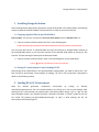
2 Loading DE in GC Environment
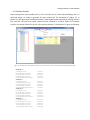
Open the Bentley generative components environment by clicking on “Bentley
GenerativeComponents.exe” file in the installed folder or by clicking on its icon on your desktop. After
opening the GC’s initial window, you need to select a previously made or empty “.gct” or “.dgn” file. We
have provided a sample “.gct” example file which is located in the folder “C:\Temp”. Double click on the
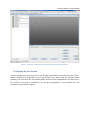
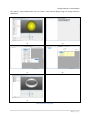
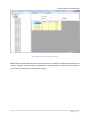
file named “DE_AoverVt_eval_generatedComponent.gct” to open it. After opening the file, GC
environment looks like the Figure 1.
Design Evolution v1 User Manual
Figure 1 Generative Component’s Environment after opening the example file.
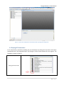
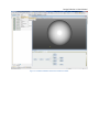
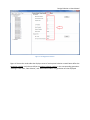
2.1 Playing all Transactions
In GC environment, transaction window, play all transactions by clicking the last black circle button
placed before text “16 Change Solid type”. By clicking so, all the circular buttons will turn to green. This
procedure is shown in Figure 2.
Playing All Transactions
5|Page
Design Evolution v1 User Manual
Figure 2 Generative Component’s Environment after playing all transactions.
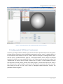
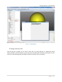
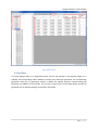
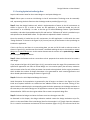
2.2 Changing the View Format
In order to change the view format, click on the “Fit View” button which is located at top of the “View 1,
Default” window to fit the geometry to the main window. If you want to see the rendered smooth
geometry, click and hold on the “View Display Mode” button to see the drop down list, and then click on
the “Smooth” item which is numbered 9. This will give the geometry a more sensible look. This
procedure is shown bellow in figure 3.
Design Evolution v1 User Manual
Figure 3 Fitting the geometry and symbolic diagram to the main window.
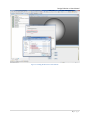
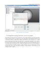
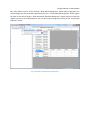
2.3 Loading required “.dll” files to GC environment.
In order to run design evolution software, you need to load some required dll files to GC environment.
All these dll files are copied in to the related folder mentioned in section 1, step 1. To load the dll files, in
GC environment’s main toolbar, click on the “Utilities” button and navigate to “Manage Feature Types”
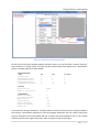
and then click on “Loaded Assemblies” (figure 4). In the opened window, click on “Select Pre-compiled
Assembly File (*.dll)” and a new window will open. In the “Select Feature Assembly File” window, find
“DEFeature.dll” file, select it and click “Open” and then click on “Load It!”. Do this procedure one more
time and select “User.DE_AoverVt_eval.dll” file to load it (figure 5). You can also check on the “Store in
Your GC Environment” control buttons to store the dll files in the GC environment for future use of DE.
After loading all the dll files click “Close” button in “Managed Loaded Assemblies” window. This
procedure is shown in figure 6.
7|Page
Design Evolution v1 User Manual
Figure 4 Loaded Assemblies button in GC Utilities Toolbar.
Design Evolution v1 User Manual
Figure 5 Loading .dll files to GC environment.
9|Page
Design Evolution v1 User Manual
Figure 6 Storing dll’s in GC environment.
2.4 Loading DE GUI by using “New Feature” tab in GC environment.
After loading all the dll files into GC environment, you can load the DE GUI to start the optimization
process. In order to do this, you need to click on the “New Feature” tab located at the bottom of the
“Transactions” window. In “New Feature” window, find “DEFeature” item, and click on the “+” symbol
before its text to open the child node. Then click on the “+” symbol before “GetFeature” item to open its
child node. Click on the white area below “Expression” tab, then select the existing geometry (here in
this example select the solid sphere). After selecting, you should see the name of the selected geometry
in the text box bellow “Expression” tab which is “behavioralSolid1”. Click on the text box one more time
and then click “Enter” or the “Ok” button. By doing so, “Design Evolution” GUI will show up. This
procedure is shown in figure 7.
Design Evolution v1 User Manual
Figure 7 Loading DE GUI
2.5 Design Evolution GUI
After the DE GUI is loaded, you can start to work with it by using “Manual” or “Optimized” design
options available in DE environment. In the next section we will discuss in details the procedure to run a
manual or optimized design job with different features available in DE environment.
11 | P a g e
Design Evolution v1 User Manual
3 DE Environment
The DE graphical user interface (GUI) acts as a front end for our application. Our GUI mainly consists of
two panels side by side.
3.1 Left Panel
Left panel in DE GUI consists of
i.
ii.
Menu strip on the top.
Tree view of the solutions.
Menu strip on the top consists of four menu buttons including
i.
ii.
iii.
iv.
New menu button
Delete button
Rename button
Run button
Delete and rename buttons are used to delete or rename a particular node in the tree view. As shown in
Figure 8, the new menu button has two buttons in it. Our DE application gives the user an option to
create a “New Manual Design” as well as “New Optimal Designs”.
Manual designs are created by generating a new design file with the parameters specified by the user
without optimizing them. In the optimal design run, several optimal solutions are created by optimizing
the design parameters.
Design Evolution v1 User Manual
Figure 8 New Optimized Design Button
Figure 9 New Manual Design Button
13 | P a g e
Design Evolution v1 User Manual
Run menu button consists of four buttons. “New Manual Design Run” button helps to generate one
manual design with the parameters specified by the user. “Initial Optimized Design Run” button Figure
10 helps to start the DE engine. “Next Generation Optimized Design Run” button Figure 11 makes the
engine to move to the next generation. User can also stop the engine by clicking on the “Stop Design
Evolution” button.
Figure 10 Initial Optimized Design Run Button
Design Evolution v1 User Manual
Figure 11 Next generation Optimized Design Run Button
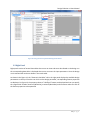
3.2 Right Panel
Right panel consists of several data tables where user can view and enter data. Based on the design run
the corresponding data table is displayed where user can enter the input parameters. Once the design
run is executed the results are shown in the result table.
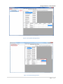
As shown in the Figure 13, the “Geometric Variables” tab in the right panel displays the available design
parameters on the top. Once the user clicks on the design parameter, corresponding feature properties
are displayed. In Figure 13, the property values of “solidType” feature are displayed and user can specify
the range which includes minimum (MinValue), maximum (MaxValue) and Increment values for each of
the feature properties to be optimized.
15 | P a g e
Design Evolution v1 User Manual
Figure 12 Geometric variables Tab
As shown in Figure 13, optimized parameters that correspond to the “optimal solution-0” are displayed
in the “Design Evaluation” tab and its corresponding design score is displayed in the design score field
on the top. When the optimal solution is selected, the corresponding optimized values and their design
score are displayed in this tab.
Design Evolution v1 User Manual
Figure 13 Design Evaluation Tab
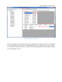
“Options” tab as shown in the Figure 14 displays the GA engine parameters that user can change. These
parameters play an important role in the optimization.
17 | P a g e
Design Evolution v1 User Manual
Figure 14 GA Engine Parameters
Figure 15 shows the result table that displays scores of each optimal solution created. Rows define the
generation number and columns define the optimal solution number in the corresponding generation.
“Average” score value, “Best Solution”, and “Best Solution Index” in a generation are also displayed.
Design Evolution v1 User Manual
Figure 15 Result Tab
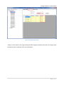
3.3 Tree View
Tree view displays nodes in an organized manner. Once a new manual or new optimal design run is
selected, the corresponding node is added to the tree view. After each generation, the corresponding
generation node with its generation number is added. The optimal solutions created during that
generation are added as its child nodes. This is shown in Figure 15 on the left panel where we have 10
generations for an optimized design run and their child nodes.
19 | P a g e
Design Evolution v1 User Manual
4 DE Data Requirement
The framework for Design Evolution (DE) is designed to work along with GC. In simple words, it
optimizes the selected design variables represented in GC design file or the transaction file with its
optimization engine. The basic functionality of this application based on the available features can be
outlined as follows:
i.
ii.
iii.
iv.
v.
Get the input design (from GC environment) to be optimized.
Provide user with a Graphical User Interface (GUI), which enable user to choose the design
parameters and specify their range.
Optimize the design parameters using Design Evolution engine, and create new design files.
Evaluate the designs and continue to next generation.
Repeat steps (iii) and (iv) until satisfactory or near-optimal solutions are obtained.
The functions outlined above describe the basic steps of DE implementation. The detailed solution
methodologies for the integrated application are discussed as following.
4.1 Design Input
The input data include design variables and the parameters used by the engine for optimization
purpose. For each design variable to be optimized, user should specify its range. The range includes
minimum value, maximum value and the increment value for that parameter. A set of default optional
GA parameters are provided for GA search while users are also allowed to change those parameters.
Input data should be created by GUI and then DE will store them in a simple text file of a predetermined
format, which can be easily transformed into a data schema. The sample input dataset is given as
follows. The DE GUI interface for interring data is presented in Figure 16. As shown in this figure, you can
click on the desired parameter (i.e. uScaleParameter) in “Feature Name” column, and then inter desired
numbers in related text boxes. After entering all the values for a feature press enter to store them and
then move to other parameters if needed.
Design Evolution v1 User Manual
Figure 16 DE interface for interring input data
DE will store all the input variables together with their values in a text file which is named “input.txt”
and is located in “C:\Temp” folder. This input text file will be used by fmGA engine later in optimization
process. A sample input file is shown bellow.
[DESIGNVARIABLES]
; Name
solidType-Value
uScaleParameter-Value
vScaleParameter-Value
wScaleParameter-Value
solidSizeParameter-Value
Min
1
1
1
1
15
Max
4
5
5
5
50
[OPTIONS]
Evaluation type
Number of top solutions
Human
3
[GAPARAMETERS]
Maximum era Number
Era generation number
Population size
Cut probability
Splice probability
Mutation probability
Random Seed
6
20
30
.017
.6
.015
0.500
Increment
1
1
1
1
0.2
In the above file, design variables (i.e. solidType-Value in above input file) are those design parameters
that the user is interested to optimize. For each of the design parameters the user needs to specify the
range as discussed. DE GUI also enables the user to specify the initial population size (i.e. 30 in above
input file) and the other engine parameters, which are given as input to the engine.
21 | P a g e
Design Evolution v1 User Manual
4.2 Solution Output
After entering all the input variables, click on “Run” and then click on “Initial Optimized Design Run” (in
optimized design run mode) to generate the initial solution file for “Generation-0” (Figure 17). In
general, for each generation of fmGA optimization, fmGA engine outputs a population of design solution
into a text file. This text file is named “solution.txt“and is located in “C:\Temp” folder. For the above
input file, the sample solution file for the 4 first optimal solutions in “Generation-0” is given as following:
Figure 17 DE interface and solution values for “Generation-0” after running “Initial Optimized Design”
SOLUTION 0
solidType-Value
uScaleParameter-Value
vScaleParameter-Value
wScaleParameter-Value
solidSizeParameter-Value
SOLUTION 1
solidType-Value
uScaleParameter-Value
vScaleParameter-Value
wScaleParameter-Value
solidSizeParameter-Value
SOLUTION 2
solidType-Value
uScaleParameter-Value
vScaleParameter-Value
wScaleParameter-Value
solidSizeParameter-Value
SOLUTION 3
solidType-Value
uScaleParameter-Value
vScaleParameter-Value
wScaleParameter-Value
solidSizeParameter-Value
1.000000
2.000000
2.000000
2.000000
30.000000
3.000000
4.000000
1.000000
3.000000
6.799999
4.000000
3.000000
5.000000
5.000000
22.600000
3.000000
2.000000
1.000000
3.000000
28.800001
Design Evolution v1 User Manual
Each of these solutions will be used by DE to generate a design or a GC transaction file, which will be
evaluated with a fitness score to quantify the merit of the design solution according to the predefined
criteria. For example, you can see all these files for “Generation-0” of the above example in “C:\Temp”
folder which are named “OR0OS0.gct”, “OR0OS1.gct”, …, OR0OS18.gct”.
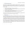
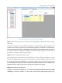
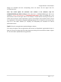
4.3 Fitness Score
Once initial population is created, the fitness of each solution should be calculated and written into a
score file. The DE engine uses the fitness values to proceed with creating next generation of solutions.
This process should be repeated till the satisfactory or near-optimal solutions are obtained. In our DE
module, a design evaluation file ( GC script file) is automatically created to evaluate the design files
created after each generation and write the corresponding fitness values into the engine score file. This
“.gct” file is located at “C:\Temp” folder and is named “evalOptimizedSolns.gct”. In order to create the
“score.txt” file which will be used by DE, this script file must be run in GC environment. Inorder to do
this, open a new GC environment, and load “evalOptimizedSolns.gct” from “C:\Temp” folder, play all
transactions and close GC (the procedure for opening a “.gct” file and playing all transactions is
discussed before in section 1.2). The following figure shows the new GC environment while
“evalOptimizedSolns.gct” is loaded and all transactions are played.
Figure 18 Loading “evalOptimizedSolns.gct” after creating each generation in order to make score files.
23 | P a g e
Design Evolution v1 User Manual
After running this script file in GC, it will create a text file with all these scores written in it which is
located in “C:\Temp” folder. The sample score file for the above example is shown below.
s1
s2
s3
s4
s5
s6
s7
s8
s9
s10
s11
s12
s13
s14
s15
s16
s17
s18
s19
7.461407407
6.09304473
1.881485593
6.09304473
2.470948345
2.470948345
7.461407407
6.09304473
1.881485593
6.09304473
2.470948345
1.881485593
2.470948345
2.470948345
2.470948345
2.470948345
2.470948345
2.470948345
7.461407407
The solution method is implemented and integrated with GUI to perform the design optimization. More
details are given as follows for the prototype implementation.
Design Evolution v1 User Manual
5 Work with DE
As discussed DE application can be used to create both manual designs and optimal designs. In this
section the working of our DE application is explained in a step wise manner.
5.1 Creating Manual Design Run
Step 1: Either open or create an initial design in the GC environment. The design must be reasonably
well, representing the basic functions that the design needs to provide (Figure 20 (a)).
Step 2: Start the Design Evolution tool, which is implemented as a feature in the GC environment as
shown in Figure 20 (b). In order to access our DE application, it should be loaded into the GC
environment as an assembly. In order to do that go to UtilitiesManage Feature TypesLoaded
Assemblies, and select Precompiled Assembly File and load our “DEFeature.dll” which is provided to you
and copied to the related folder before. This procedure is explained in details in section 2.
Once the assembly is loaded into the GC environment, the DE Application is visible with the name
“Design Evolution” as shown in the Figure 20 (b). You can pass any of the features in the input design to
initialize the application.
If this is the first run and there is no pre-existing data, you see our DE GUI with a welcome screen as
shown in Figure 20 (b), and the new menu button is activated enabling the user to choose either manual
design run or optimal design run. As this section demonstrate the creation of a manual design, click on
the new manual design run button.
Note that, after opening DE GUI if there is any pre-existing data available for the design file it will display
the previous run nodes and all the other preexisted data as shown in the Figure 19. This implies that
user had worked on this design file and ran one optimize design run and one manual design run. The
user has option to view all the interested data. The main advantage of this data persistence is that it
prevents data loss.
25 | P a g e
Design Evolution v1 User Manual
Figure 19 Preexisted data for manual and optimal design
Step 3: Select the features and set a new value to their properties that need to be varied to create a
new design.
As shown in the Figure 20 (c), the available design features and their feature type are displayed in the
top table. Once a feature is selected their corresponding properties are displayed in the bottom table.
The current value of the property is also displayed in the table. The user needs to give a new value to
the property which he is interested to change. For example change solid type to 3 and solid size
parameter to 15. Figure 20 (c) shows the user inputs.
Step 4: Click the new manual design run button.
After providing the new values and new manual design run is clicked, a new manual design is created
with the user defined parameter values in the same folder as the input design file is (which is C:\Temp
for this example) with name “MR0MS0.gct”. A child node is added to the tree view which corresponds to
the manual design file created. If this node is selected, the optimal parameters in the new design file are
displayed as shown in Figure 20 (d). The current value and new value are displayed.
Step 5: Opening the new created GC file.
In order to view the new design file, run a new GC environment and open the new created
“MR0MS0.gct” file which is located in “C:\Temp” folder to see the new designed model (Figure 20 (e)).
Design Evolution v1 User Manual
The above 5 steps demonstrate how to create a new manual design using our Design Evolution
application.
(a)
(b)
(c)
(d)
(e)
Figure 20 Manual Design Run
27 | P a g e
Design Evolution v1 User Manual
5.2 Creating Optimization Design Run
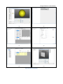
Steps 1 and 2 remain same for the manual design run and optimal design run.
Step 1: Either open or create an initial design in the GC environment. The design must be reasonably
well, representing the basic functions that the design needs to provide (Figure 21 (a)).
Step 2: Start the Design Evolution tool, which is implemented as a feature in the GC environment as
shown in Figure 21 (b). In order to access our DE application, it should be loaded into the GC
environment as an assembly. In order to do that go to UtilitiesManage Feature TypesLoaded
Assemblies, and select Precompiled Assembly File and load our “DEFeature.dll” which is provided to you
and copied to the related folder before. This procedure is explained in details in section 2.
Once the assembly is loaded into the GC environment, the DE Application is visible with the name
“Design Evolution” as shown in the Figure 21 (b). You can pass any of the features in the input design to
initialize the application.
If this is the first run and there is no pre-existing data, you see our DE GUI with a welcome screen as
shown in Figure 21 (b), and the new menu button is activated enabling the user to choose either manual
design run or optimal design run. As this section demonstrate the creation of an optimal design, click on
the new optimal design run button.
Step 3: Select the features and set a new value to their properties that need to be varied to create a
new design.
If you compare the Figure 20 (c) with Figure 21 (c), you need to enter the range of the parameters to be
specified as opposed to new value in manual design run. User need to specify the minimum, maximum
and increment values for each of the parameter that needs to be optimized. Set the engine parameters
which includes the number of design alternatives to be generated for each iteration/generation and
other related optimization settings as shown in Figure 21 (d).
Step 4: Click on the initial Optimized Design Run button.
Initial Generation of the population is generated by the DE engine. As shown in the Figure 21 (e) the
initial set of optimal solutions are created and are added as nodes to the tree view. Clicking on the
optimal solution node display the corresponding optimal solution parameters in the design evaluation in
the same way as the manual design run. DE application creates an input file based on the user input as
discussed earlier. DE file uses the engine solution file to create new optimal design files.
Step 5: Evaluate the Designs and write the fitness score into the engine score file.
As discussed in this chapter, the design evaluation module creates the design evaluation script file,
which is in the same folder of the initial design (here for this example it is C:\Temp). Open the evaluation
file in a new GC environment and execute all the transactions (Figure 21 (f)). This ensures that all the
Design Evolution v1 User Manual
designs are evaluated and their corresponding scores are written into the engine score file
(C:\Temp\score.txt).
Note: User should update the evaluation score attribute in the evaluation script file
(evalOptimizedSolns.gct) before running it. The script line in “evalOptimizedSolns.gct” that to be
modified is Print("s"+scoreFileIndex+"\t"+simpleAnalysisValue.Value) where the bolded text is the
desired fitness value for GA engine. Here for this example, a simple function consisting of the ratio of
surface area to volume is used as optimization criteria or the evaluation score attribute, which is stored
as a transaction in “DE_AoverVt_eval_generatedComponent.gct” file. To view this, you can open this
script file in text editor software (i.e. notepad), and view/modify this transaction for desired
optimization criteria.
Step 6: Click on the next generation optimized design run button.
This moves the engine to the next generation and the next set of population is generated as shown in
Figure 22. The user can keep track of the best solutions by looking at the result table as shown in Figure
22. The result table is updated after every generation.
29 | P a g e
Design Evolution v1 User Manual
(a)
(b)
(c)
(d)
(e)
(f)
Figure 21 Optimal Design Run
Design Evolution v1 User Manual
Figure 22 Next Generation Optimal Solutions
Step 7: Repeat steps 5 and 6 until the best optimal solutions are obtained. The above steps demonstrate
creation of optimal solutions using our DE application. Our DE application implements data persistence
so that user can save the work session before closing it.
31 | P a g e