1
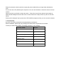
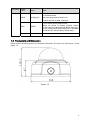
HD IR Vandal Proof IP Dome Camera Quick Start Guide
Version 1.0
Welcome
Thank you for purchasing our IP camera!
This quick start guide is designed to be a reference tool for your system.
Please keep this start guide well for future reference.
Please open the accessory bag to check the items one by one in accordance with the list below.
Contact your local retailer ASAP if something is missing or damaged in the bag.
Before your operation please read the following instructions carefully.
1.Electrical safety
All installation and operation here should conform to your local electrical safety codes.
The power shall conform to the requirement in the SELV (Safety Extra Low Voltage) and the Limited
power source is rated 12V DC or 24V AC in the IEC60950-1.
We assume no liability or responsibility for all the fires or electrical shock caused by improper handling
or installation.
We are not liable for any problems caused by unauthorized modification or attempted repair.
2.Transportation security
Heavy stress, violent vibration or water splash are not allowed during transportation, storage and
installation.
3.Installation
Do not apply power to the camera before completing installation.
Please install the proper power cut-off device during the installation connection.
Always follow the instruction guide the manufacturer recommended.
4.Qualified engineers needed
All the examination and repair work should be done by the qualified service engineers.
We are not liable for any problems caused by unauthorized modifications or attempted repair.
5.Environment
This series IP camera should be installed in a cool, dry place away from direct sunlight, inflammable,
explosive substances and etc.
Please keep it away from the electromagnetic radiation object and environment.
Please make sure the CCD (CMOS) component is out of the radiation of the laser beam device.
Otherwise it may result in CCD (CMOS) optical component damage.
Please keep the sound ventilation.
Do not allow the water and other liquid falling into the camera.
6. Daily Maintenance
Please shut down the device and then unplug the power cable before you begin daily maintenance
work.
Do not touch the CCD (CMOS) optic component. You can use the blower to clean the dust on the lens
surface.
Always use the dry soft cloth to clean the device. If there is too much dust, please use the water to
dilute the mild detergent first and then use it to clean the device. Finally use the dry cloth to clean the
device.
Please put the dustproof cap to protect the CCD (CMOS) component when you do not use the camera.
7. Accessories
Be sure to use all the accessories recommended by manufacturer.
Before installation, please open the package and check all the components are included.
Contact your local retailer ASAP if something is broken in your package.
Accessory Name
IPC Unit
MD9M data converter cable
Accessories bag
Quick Start Guide
Warranty Card
Certificate Card
CD
Amount
1
1
1
1
1
1
1
Table of Contents
1
2
3
4
Framework...................................................................................................................................5
1.1
MD9M Data Converter Cable .....................................................................................5
1.2
Framework and Dimension.........................................................................................6
Installation ...................................................................................................................................8
2.1
Device Installation ........................................................................................................8
2.2
SD Card Installation ...................................................................................................11
2.3
Lens Adjustment.........................................................................................................12
Quick Configuration Tool.........................................................................................................13
3.1
Overview ......................................................................................................................13
3.2
Operation .....................................................................................................................13
Web Operation..........................................................................................................................16
4.1
Network Connection...................................................................................................16
4.2
Login and Logout........................................................................................................16
Appendix Toxic or Hazardous Materials or Elements ...............................................................19
1 Framework
1.1 MD9M Data Converter Cable
You can refer to the following figure for MD9M data converter cable information. See Figure 1-1.
Figure 1-1
Please refer to the following sheet for detailed information.
Port Name
Function
Connection
Note
VIDEO OUT
Video
port
output
BNC
Output analog video signal. It can connect to the
TV monitor to view the video.
AUDIO IN
Audio
port
input
RCA
Input audio signal. It can receive the analog audio
signal from the pickup.
AUDIO OUT
Audio
port
output
RCA
Output audio signal to the devices such as the
sound box.
12V DC/AC24V
Power
port
input
/
Power port. Input DC 12V/AC 24V
I/O
I/O cable port
/
Connect to MD9M data converter cable.
LAN
Network port
Ethernet
port
Connect to standard Ethernet cable.
Please refer to the follow sheet for detailed information of MD9M data converter cable.
Port Name
Cable
Color
Name
Note
I/O
Pin
Yellow
RS485_A
RS485_A port. It is to control the PTZ.
Black
RS485_B
RS485_B port. It is to control the PTZ.
Red
ALARM_COM
Alarm output public port.
Brown
ALARM_IN1
Alarm input port 1. It is to receive the on-off signal
from the external alarm source.
Grey
ALARM_IN2
Alarm input port 2. It is to receive the on-off signal
from the external alarm source.
Port
5
Port Name
Cable
Color
White
Name
ALARM_NO
Note
Alarm output port. It is to output the alarm signal
to the alarm device.
NO: normal open alarm output port.
It works with the ALARM_COM port.
It is to restore factory default setup.
Blue
RESET
Orange
GND
When the device is working properly, please
connect the blue cable (restore default setup port)
to the orange cable (GND signal) for 5 seconds,
the device can resume factory default setup.
Ground port
1.2 Framework and Dimension
Please refer to the following figure for dimension information. The unit is mm. See Figure 1-2 and
Figure 1-3.
Figure 1-2
6
Figure 1-3
7
2 Installation
This series IPC can be put on the table to realize surveillance. Or you can use the bracket or the
in-ceiling installation to realize the hang function. Please refer to the steps listed below.
2.1 Device Installation
Step 1
Use the inner hexagonal wrench (provided) to loose the three inner hexagon screws in the dome
cover and then open the cover. See Figure 2-1.
Figure 2-1
Step 2
Use the inner hexagonal wrench (provided) to loose the three inner hexagon screws in the dome
and then remove the device pedestal. See Figure 2-2.
8
Figure 2-2
Step 3
Draw out the cable exit and four screw holes in the installation position according to the device
pedestal. Dig the four plastic expansion bolt hole and cable exit. Insert the four plastic expansion
bolts into the screw holes
Step 4
Adjust the camera pedestal to the proper position and then draw the cable through the cable exit
you just dug in the ceiling (wall). Line up the four screw holes in the device pedestal to the four
plastic expansion bolt holes in the installation position. Put the four self-tapping screws in the
device pedestal and then use the screwdriver to secure the screws in the four plastic expansion
bolts firmly.
Step 5
Adjust the device position and line up the three inner hexagon screws of the device to the three
holes of the installation position. Put the three inner hexagon screws into the screw holes at the
bottom of the pedestal. Use the inner hexagon screwdriver to fix firmly. See Figure 2-3.
9
Figure 2-3
Step 6
Adjust the X-Y-Z axis module to turn the device to the proper monitor angle. Please follow the
steps listed below to adjust.
z Slightly loose the screws at the two sides of the X-Y-Z module manually, you can adjust the
module tilt rotation angle (15°~90°).
z Slightly loose the screw of the pressing slice, you can adjust the video rotation angle of the
module (0°~355°)
Adjust the turning ring of the pedestal, you can adjust the module pan rotation angle (0°~
355°).
Please note, the screws in the following figure are the optical adjustment component.
Please make sure it is outward and do not allow it to touch the X-Y-Z axis module. See
Figure 2-4
z
Figure 2-4
Step 7
Put the dome cover back and then put the three inner hexagon screws into the holes of the
device. Use the inner hexagonal wrench to fasten these three screws. See Figure 2-5
10
Figure 2-5
2.2 SD Card Installation
Important
Before you install the SD card, please unplug he power cable to shut down the device!
First, please refer to the step1 in the chapter 2.1 to open the device.
Second, please adjust the proper position to install the SD card.
Last, please refer to the step 7 in the chapter 2.1 to complete the installation. See Figure 2-6.
Figure 2-6
11
2.3 Lens Adjustment
Step 1
Slightly loose the screw B manually and then turn the screw B slowly. Adjust the lens focus
distance to the proper position according to the monitor video. See Figure 2-7.
Step 2
Use the flat screwdriver to loose the screw A slightly and then turn the Screw A slowly. Adjust the
lens focus to get the clear video and then use the flat screwdriver to secure the screw firmly.
Step 3
When you are adjusting the screw A, the video may becomes blur. Please slightly adjust the
screw B manually to get the vivid video. Finally fix the screw.
Figure 2-7
12
3 Quick Configuration Tool
3.1 Overview
Quick configuration tool can search current IP address, modify IP address. At the same time, you
can use it to upgrade the device.
Please note the tool only applies to the IP addresses in the same segment.
3.2 Operation
Double click the “ConfigTools.exe”icon, you can see an interface is shown as in Figure 3-1.
In the device list interface, you can view device IP address, port number, subnet mask, default
gateway, MAC address and etc.
Figure 3-1
Select one IP address and then right click mouse, you can see an interface is shown as in Figure
3-2.
13
Figure 3-2
Select the “Open Device Web” item; you can go to the corresponding web login interface. See
Figure 3-3.
Figure 3-3
If you want to modify the device IP address without logging in the device web interface, you can
go to the configuration tool main interface to set.
In the configuration tool search interface (Figure 3-1), please select a device IP address and then
double click it to open the login interface. Or you can select an IP address and then click the
Login button to go to the login interface. See Figure 3-4.
In Figure 3-4, you can view device IP address, user name, password and port. Please modify the
corresponding information to login.
Please note the port information here shall be identical with the port value you set in TCP port in
Web Network interface. Otherwise, you can not login the device.
If you are use device background upgrade port 3800 to login, other setups are all invalid.
Figure 3-4
After you logged in, the configuration tool main interface is shown as below. See Figure 3-5.
14
Figure 3-5
For detailed information and operation instruction of the quick configuration tool, please
refer to the Quick Configuration Tool User’s Manual included in the resources CD.
15
4 Web Operation
This series IPC product support the Web access and management via PC.
Web includes several modules: monitor channel list, record search, alarm setup, system
configuration, PTZ control, monitor window and etc.
IP camera factory default setup:
z IP address: 192.168.1.108.
z User name: admin
z Password: admin
4.1 Network Connection
Please follow the steps listed below for network connection.
z Make sure the IPC has connected to the network properly.
z IPC IP address and PC IP address shall be in the same network segment. IPC default IP
address is 192.168.1.108. If there is router, please set the corresponding gateway and
subnet mask.
z Use order ping ***.***.***.***(* IP camera address) to check connection is OK or not.
4.2 Login and Logout
Open IE and input IP camera address in the address bar.
For example, if your camera IP is 192.168.1.108, then please input http:// 192.168.1.108 in IE
address bar. See Figure 4-1.
Input your IP
address here
Figure 4-1
System pops up warning information to ask you whether install control webrec.cab or not.
Please click OK button, system can automatically install the control. When system is upgrading, it
can overwrite the previous Web too.
If you can’t download the ActiveX file, please check whether you have installed the plug-in to
disable the control download. Or you can lower the IE security level. See Figure 4-2.
16
Figure 4-2
After installation, the interface is shown as below. See Figure 4-3.
Please input your user name and password.
Default factory name is admin and password is admin.
Note: For security reasons, please modify your password after you first login.
Figure 4-3
After you logged in, you can see the main window. See Figure 4-4.
17
Figure 4-4
Please refer to the HD IR Vandal Proof IP Dome Camera Web Operation Manual included in the
resource CD for detailed operation instruction.
18
Appendix Toxic or Hazardous Materials or Elements
Component
Name
Toxic or Hazardous Materials or Elements
Pb
Hg
Cd
Cr VI
PBB
PBDE
Circuit Board
Component
○
○
○
○
○
○
Device
Construction
Material
○
○
○
○
○
○
Wire and Cable
○
○
○
○
○
○
○
○
○
○
○
○
○
○
○
○
○
○
Packing
Components
Accessories
O: Indicates that the concentration of the hazardous substance in all homogeneous materials in
the parts is below the relevant threshold of the SJ/T11363-2006 standard.
X: Indicates that the concentration of the hazardous substance of at least one of all
homogeneous materials in the parts is above the relevant threshold of the SJ/T11363-2006
standard. During the environmental-friendly use period (EFUP) period, the toxic or hazardous
substance or elements contained in products will not leak or mutate so that the use of these
(substances or elements) will not result in any severe environmental pollution, any bodily injury or
damage to any assets. The consumer is not authorized to process such kind of substances or
elements, please return to the corresponding local authorities to process according to your local
government statutes
Note:
z
This quick start guide is for reference only. Slight difference may be found in user
interface.
z
All the designs and software here are subject to change without prior written notice.
z
If there is any uncertainty or controversy, please refer to the final explanation of ours.
z
Please visit our website or contact your local service engineer for more information.
19