1
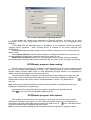
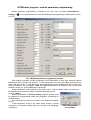
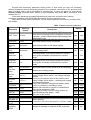
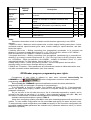
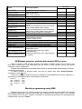
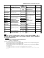
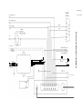
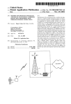
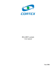
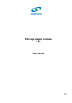
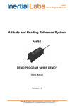
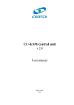
RS-Global system GSM/GPRS/SMS/GPS object module Programming manual 2005 Table of contents Table of contents...............................................................................................................................2 General information.......................................................................................................................... 3 Device features...................................................................................................................................3 Device technical characteristics....................................................................................................3 Preparing for programming.............................................................................................................4 GPSReader program: general information................................................................................5 GPSReader program: settings......................................................................................................5 GPSReader program: data reading.............................................................................................6 GPSReader program: data upload..............................................................................................6 GPSReader program: module parameter programming...................................................... 7 GPSReader program: programming user rights. ...................................................... 9 GPSReader program: message sending programming. .........................................11 GPSReader program: working with module GPS receiver....................................... 13 Module programming using SMS.............................................................................. 13 Enclousure1. Module wiring diagram........................................................................ 15 Enclosure 2. Tracking View program command list................................................. 16 ©Korteks Līksnas iela 7, Rīga, Latvija, Tel./fakss: (+371) 7505603, (+371) 7505604 E-mail: [email protected], http://www.cortex.lv 2 General information GSM/GPRS/SMS/GPS object module is a device, which is mounted on a vehicle for distant control of its systems and for locating vehicle’s position. Object’s location (geographical coordinates) is determined with the help of GPS (Global Positioning System). This information, along with information about controlled systems and object’s parameters status transmits to user through GSM web on demand, or using built in algorithm. If GSM web operator provides data transmitting through GPRS, than object movement control is realized in «online» mode, that means, that information about object coordinates is transmitted not on demand, but right after their change on adjusted value. Device features 12-channel GPS-receiver with NMEA-0183 protocol; Writing in non-volatile memory 1950 (3900) route points and 185 (375) events. RS-232 port for reading GPS-information, route, event log, and for programming blockparameters. GPS-receiver and GSM-modem status indicationIgnition control input Input for alarm signal connectionInput for panic button connection Input for status signal connection (armed/disarmed)Input for on-board power control Input for analogue signal (ADC) controlAlarm activation output Engine blocking outputGeneral purpose output Adjusted speed exceeding controlLeaving adjusted zone controlUp to 4 user support Two on-the-fly switchable message modes: «text» and «modem»Tracking mode «Online» mode Periodic channel test possibility: from 1 hour to 10 days Device technical characteristics. Number of GPS-receiver channels 12 GPS-receiver output protocol NMEA-0183 GSM-protocol E-GSM 900/1800 GSM-modem Wavecom Wismo SIM interface 3В Number of users 4 Output capability 1А Maximum voltage on closed output 40V Maximum voltage on inputs 40V Measured ADC value range 0 – 4V Supply voltage * 9 – 18 V Input current (at 12V power supply), at most 90mA Overall dimensions 145х97х24 * When using standby power supply, voltage range from 9 to 36V. ©Korteks Līksnas iela 7, Rīga, Latvija, Tel./fakss: (+371) 7505603, (+371) 7505604 E-mail: [email protected], http://www.cortex.lv 3 Module appearance Pic. 1 GPS-GSM module. 1.GSM antenna connection joint (FME). 2.Peripheral device connection joint (DB15M). 3.GPS antenna connection joint (MCX). Pic. 2 GPS and GSM antennas. Preparing for programming. Module programming is made with the help of the special program GPSReader through computer СОМ-port. Before programming module must be prepared for work i.e. SIM-card must be inserted, and at least one user («master») must be registered - see module manual p.5 «module basic setting». After that module is connected to computer СОМ-port and connected to power supply. GSM antenna must be connected to module, it isn't necessary to connect GPS antenna. After connecting power supply, module indicator must flash green and after successful load of SIM-card parameters green indicator should start to blink. If it doesn't, it's necessary to make sure that SIMcard is inserted into the block and it's PIN-code – 0000. When block is ready for work, READY message (98 – in «modem» mode) is send to all registered users. At this time indicator starts to blink red (if GPS antenna is connected and coordinate determination is possible), or flashes red (if it's impossible to determine coordinates). To initiate module programming mode it's necessary to send him from «master's» phone command 8.хххх, where хххх – module PIN-code (by default – 1234). As an answer module sends message PRG MODE (97). After that green light is turned off and module is ready for programming. Note. Programming must be initiated in 2 minutes, or module will return in work mode. GPSReader program: general information GPSReader program is designed for module parameters programming, configuration of user rights and message sending addresses, GPS receiver working control, downloading route and event log from module memory and sending it to server. Program's main window appearance is shown on Pic.1. Pic. 1 Program main window. All program's function and setting start is made through main menu and duplicated by icons, located at the top of the window (see Pic.1.) GPSReader program: settings Program settings are settings of computer serial port for connection with module and adjusting parameters of the server, on witch module information should be sent. Parameter adjusting window can be opened either through main menu (Settings), or by icon. Pic. 2 Port settings window. In Ports column should be chosen number of computer serial port, through witch communication with module would be realized. In “Settings” column - this port parameters. For work with described module port parameters should be like ones on the Pic.3. Pic. 3 Server parameters adjusting window. In this window are shown server parameters «Tracking» software, on which can be send information about route, downloaded from the module through port (see paragraph «Data reading»). In the Host field are specified name or IP-address of the computer, which has installed Tracking Server (localhost – when Tracking Server is installed on the same computer with GPSReader). In the Port field are specified number of the port which is used by server to receive data. By default – 900. In the Update data (ms) field are specified delay in sending information lines on server. It is recommended to increase when connection with server quality is low. Send invalid coordinate checkbox is recommended to leave unfilled, because otherwise server will accept messages with invalid coordinates that can cause errors in program functioning. GPSReader program: data reading With the help of the program it is possible to read information from the module through serial port for it's handling and/or sending to server. This reading method is used if module doesn't support reading through GPRS mode, or data transmitting through GPRS is not supported by mobile communication operator on the current territory. Just like through GPRS connection, through serial port from the block can be read two data types: route (1950 or 3900 points) and event log (185 or 370 entries). Reading initialization is realized either though main menu (Action / Route download or Action / Log download) or with icon. Note. Before data reading initialization module must be switched in programming mode (see paragraph «Preparing for programming»). Information that is downloaded from the module is placed in user specified text file. With (Stop) icon you can interrupt data reading process. GPSReader program: data upload After reading route information, it's necessary to send them to server, so route could be displayed in Tracking View program. For this exists data upload function. For it's initialization is necessary to activate Action/Data upload command in main menu (or icon), and than choose file which contains route information and start upload. Note. For successful data upload server parameters should be specified in program settings. GPSReader program: module parameter programming Module parameter programming is initiated by the main menu command Action/General setting or icon. Current parameters are read and displayed in programming window that is shown on Pic.4. Pic. 4 Module parameter programming window. After setting necessary module parameters press ОК button. In that case renewed module parameters will be written into module. To save parameters into file press Save and specify file name and save route. To load previously saved parameters press Load and specify the file from which parameters will be loaded. Load and Save parameters are available only if parameter window is active (i.e. before ОК button is pressed). Some parameters can be edited in user mode, some - only in installer mode, and some are informational and cannot be edited. Parameter descriptions are given in Table 1. Before initialization of General setting program module must be switched in programming mode (see paragraph «Preparing for programming»). If it's impossible to connect to module, error window will appear (Pic.5.). If that happened, check if the cable works properly, module Pic. 5 Connection connection to computer validity and port settings (see paragraph error window «Settings»). Program has preliminary parameter setting mode. In that mode you cam set necessary module parameters without connecting module to the computer, save them to file, and than load them to module when it will be accessible for programming. To enter this mode you must choose General setting command when module is not connected and press ОК in connection error window (Pic.5.). In that case parameter programming window will open with zero data. After entering necessary parameter value press Save and specify file name and save route. Later, when module will be connected, you can load parameters from that file, and write them into module. Table 1. Module general parameters. Value by default Parameter Description WDT_Timer 15 min. Query time Zones response time Speed for block 3 sec. Determines the time, during which GPS receiver can work without receiving certain coordinates. After time expiration, receiver restarts and sends message that coordinates is lost. GPS-receiver query time with the purpose to gain information about current coordinates. 500 msec. Input response time on the status change. 46.3 km/h Latitude dead zone 5.0 Longitude dead zone 5.0 Speed over value Test time value Not specified 24 h Maximum vehicle speed value, at which engine blocking takes place1 Latitude shifting value (in geographical seconds), exceeding which, route entry is made into memory, and current coordinate is transmitted in «online» mode.2 Longitude shifting value (in geographical seconds), exceeding which, route entry is made into memory, and current coordinate is transmitted in «online» mode.3 Speed value, exceeding which, message with information about current speed value is transmitted. Query time 10 sec Module test message period. Value (in conventional units) of the module power supply voltage. When lower – low voltage message is send. Value (in conventional units) of the module power supply voltage. When higher – module power supply is considered restored. Flags, that determine message transmitting mode («text» or «modem») according to users. Module PIN-code that is used for it's identification. Also can be changed by SMS SIM-card PIN-code. Used for locking module on specific SIM-card. By default – 0000 Not used in this version Time zone, which module is used in. Module software version. If set on 0, module uses factory presets. Connection with server test period in «online» mode4 Attempts for activating GPRS 2 Number of attempts to establish GPRS connection. Bat low const. 155 c.u. Bat norm const. 175 c.u. Txt format 0F Module PIN 1234 SIM PIN User for call Time zone 0000 -------3 Firmware ver in online Editing User Inst. Yes Yes Yes Yes No Yes No Yes Yes Yes Yes Yes Yes Yes Yes Yes No Yes No Yes No Yes Yes Yes Yes Yes Yes Yes Yes Yes No Yes No Yes Value by default Parameter Reconnect time for online Attempts for reconnect online 3 min 3 APN SIM ID TCP port Server IP Tlf number 920 Description Time interval between attempts of module to connect to server. Number of attempts to establish connection with server. APN for logging on when GPRS connection is established. Information is provided by mobile operator. SIM-card identificator. 5 Computer port, which is used to connect to server. Server IP address. Module phone number (written down at authorization)5 Editing User Inst. No Yes No Yes Yes Yes No Yes Yes No Yes Yes No No Notes. Parameters that written in italic is related to module that has opportunity to use GPRS channel: 1.Speed for block – Maximum vehicle speed value, at which engine blocking takes place. If when command received, speed exceeds given value, module waiting for speed decrease, and then blocks the engine. 2.Latitude dead zone – Shifting converting from geographical coordinates Lt (in seconds) into distance S (in meters) is made using formula: S = (Le* π/Gr)*Lt=30,8*Lt, where Le=12714000m – Earth circumference, Gr=1296000 – number of seconds in circuit. 3.Longitude dead zone – Shifting converting from geographical coordinates Lg (in seconds) into distance S (in meters) is made using formula: S = ((Le*π/Gr)*Lg)*Cos(Lt)=30,9*Lg*Cos(Ltt), where Le= 12756000m – Earth circumference, Gr=1296000 – number of seconds in circuit, Lt – point geographical latitude. For Riga latitude, formula will be: S = 16.8*Lg. 4.Query time in online – server query time by module. The more this period, the less will be summary traffic, but the longer message delivery to module. 5.SIM ID and Tlf number – those parameters are informational, cannot be edited and can be seen only after successful module authorization (see User manual). GPSReader program: programming user rights. Programming of user rights is initiated by main menu command Action/Config for COMMAND or by icon. At this time current module configurations read from module and opens programming window (Pic.6.) Before Config for COMMAND command initialization module should be switched into programming mode (see paragraph «Preparing for programming»). If it's impossible to connect to module, error window will appear (Pic.5.). If that happened, check if the cable works properly, module connection to computer validity and port settings (see paragraph «Settings»). As you can see on the left side there are a list of commands supported by module, and in columns to the right you can allow () or forbid ( ) given command to proper user (U1 – U4), and also allow or forbid module command acknowledgement transmitting (Replay). Available command description is given in Table 2. When done configuring module press ОК. In that case renewed parameters will be written into module. To save module configuration into file press Save and specify file name and save route. To load previously saved configuration press Load and specify he file from which configuration will be loaded. Load and Save parameters are available only if parameter window is active (i.e. before ОК button is pressed). Рис. 5 User rights configuration window Program has preliminary parameter setting mode. In that mode you cam set necessary module parameters without connecting module to the computer, save them to file, and than load them to module when it will be accessible for programming. To enter this mode you must choose Config for COMMAND command when module is not connected and press ОК. In that case parameter programming window will open with zero data. After setting necessary configuration press Save and specify file name and save route. Later, when module will be connected, you can load configuration from that file, and write it into module. Table 2. Commands supported by module Command Command description Note Allows switching message mode between «modem» and «user». In the first case messages Recommended to Switching mode are transmitted in text form, in the second – allow to all users. codes with current coordinates. Allows to request module status (it's input and Check status output status) Set ALARM Allows activating alarm on the object. Cancel ALARM Allows deactivating alarm on the object. Allows activating alarm on the object for indicated Set ALARM on time time. Activate OUT2 Allows to activate Output 2 Deactivate OUT2 Allows to deactivate Output 2 Activate OUT2 on time Allows activating Output 2 for indicated time. Block engine Allows to block the engine Unblock engine Allows to unblock the engine User who receives Allows to turn on object tracking mode with given Start tracking information is assigned time interval (through SMS) separately. Stop tracking Allows turning off object tracking mode. Command Check coordinate Check ADC Set normal state Set speed limit Set shift limit Program mode Command description Allows to request object coordinates Allows to request module analogue input status (ADC value) Allows to set module current status as normal (armed, inputs and outputs normal) Allows to set speed value, exceeding which message is send. Allows to set latitude and longitude shifting value, exceeding witch message is send. Module config Allows switching module in programming mode. Allows to request number of the first user (master). Allows to request number of the second user Allows to request number of the third user Allows to request number of the fourth user Allows to delete number of the second user Allows to delete number of the third user Allows to delete number of the fourth user Allows to set or change number of the first user Allows to set or change number of the second user Allows to set or change number of the third user Allows to set or change number of the fourth user Allows realizing module parameter adjustment through SMS. Change module PIN Get route Get log Work online (GPRS) Work offline (GPRS) Allows to change module PIN-code Allows to download route from module memory Allows to download log from module memory Allows to switch module in «online» mode Allows to switch module in «offline» mode Show User1 Show User2 Show User3 Show User4 Erase User2 Erase User3 Erase User4 Change/Set User1 Change/Set User2 Change/Set User3 Change/Set User4 Note Used at module start installation Used for adjusted speed exceeding control. Recommended only for «master» Recommended only for «master» Only for «master»! Only for «master»! Recommended only for «master» Only for «master»! Only for «master»! Only for «master»! Only for «master»! GPSReader program: message sending programming. User rights programming is initiated from main menu Action/Config for EVENT or with icon. At this time current module configuration read from module and opens programming window (Pic.7) Pic. 6 Message sending programming window. Before Config for EVENT command initialization module should be switched into programming mode (see paragraph «Preparing for programming»). If it's impossible to connect to module, error window will appear (Pic.5.). If that happened, check if the cable works properly, module connection to computer validity and port settings (see paragraph «Settings»). As you can see on the left side there are a list of events that appear in the module and assigned for sending, and in columns to the right you can allow () or forbid ( ) given message sending to proper user (U1 – U4). Description of events that can be send is given in Table 3. When done configuring module press ОК. In that case renewed parameters will be written into module. To save module configuration into file press Save and specify file name and save route. To load previously saved configuration press Load and specify he file from which configuration will be loaded. Load and Save parameters are available only if parameter window is active (i.e. before ОК button is pressed). Program has preliminary parameter setting mode. In that mode you cam set necessary module parameters without connecting module to the computer, save them to file, and than load them to module when it will be accessible for programming. To enter this mode you must choose Config for EVENT command when module is not connected and press ОК. In that case parameter programming window will open with zero data. After setting necessary configuration press Save and specify file name and save route. Later, when module will be connected, you can load configuration from that file, and write it into module. Table 3. Events Message Event Event description «user» «modem» Coordinate in Track Current coordinate in tracking mode. mode IGNITION ON Ignition on in «armed» mode. * Ignition off (send only after IGNITION ON IGNITION OFF event). Event Event description Car ALARM Signalization system activated. Signalization system is switched in standby mode or turned off. Alarm button pressed. Alarm button released or unlocked. Object switched in «armed» mode. Object switched in «disarmed» mode Module power supply voltage is low Module power supply voltage is restored to normal Vehicle on-board power source is off (when using uninterruptible power supply). Vehicle on-board power source is restored (when using uninterruptible power supply).) Maximum allowed speed is exceeded Vehicle left adjusted zone Unable to determine certain coordinates during fixed time period Module is ready to work. Module switched in programming mode. Periodic test message. Vehicle engine blocked. Unable to establish GPRS connection Connection with server error, when downloading route Connection with server error, when downloading log Connection with server error, when trying to go «online» Cancel ALARM PANIC Cancel PANIC ARMING DISARMING BATTERY LOW BATTERY Ok POWER OUT POWER Ok SPEED OVER SHIFT OVER Lost coordinate Ready to work Program mode entry Test message Engine blocked GPRS error Route: connection error Log: connection error Online: connection error Message «user» «modem» GPSReader program: working with module GPS receiver When in working mode, module transmits information in NMEA protocol on it's RS-232 port from GPS receiver port. This information can be used to check receiver status and vehicle navigation system organization. Program allows displaying information from receiver in terminal mode, and sending on receiver some query-commands. To switch program in terminal mode, you have to initiate main menu Action/Terminal command or press icon. If done so, in program terminal window are displayed certain NMEA protocol lines, and there is opportunity to call additional lines using following commands: Ctrl+F1 – GGA lineCtrl+F2 – GLL lineCtrl+F3 – GSA lineCtrl+F4 – GSV line Module programming using SMS. Starting from version 2.5., module supports parameter programming using SMS. This function is provided by 99.хх...хх command, where хх... хх – parameter code and it's value. This command only available to the first user («master»). Available for programming parameter list and appropriate configurations is given in Table 4. Table 4. Parameters, programmed using SMS Way of sending SMS/GPRS SMS 99.03 99.I211.21.211.2 ----- APN SMS 99.Ainternet.lmt.lv --- Server port SMS 99.P920 99.D15,15 --- (Value from 1 to 3600 5,5 Command 99.<hours> 99.I<IP> 99.A <access point> 99.P<port> Description 1 Time zone Server IP address 99.D<Latitude, longitude(sec)> Dead zone value SMS/GPRS 99.Т<hours> SMS/GPRS 99.R<tries> 99.G<sec> 99.O<sec-> 99.M<min> 99.B<mode> Time between test sends Number of tries to restore connection with server How often coordinates are requested How often server information is requested Time between tries to restore connection with server Engine blocking mode2 99.L0 Allow route «upload» (p. 8.6) Forbid route «upload» (p. 8.6) 99.C1 99.C2 99.L1 SMS/GPRS SMS/GPRS SMS/GPRS Example sec.) 99.Т24 (from 1 to 255 hours) 99.R3 (from 1 to 255) 99.G3 (from1 to 255 sec.) 99.O10 (from1 to 255 sec .) By default 24 3 3 10 SMS/GPRS 99.М5 (from1 to 255 min.) 3 SMS/GPRS 99.В1 (from 1 to 4) 1 SMS/GPRS 99.L1 allowed SMS/GPRS 99.L0 Show net configuration SMS 99.C1 Show time and engine blocking mode settings SMS 99.C2 Notes: 1)In «User» mode time of creation is added to message: for example, 14:37:11 READY (v.1.3). To receive time right, it's necessary to keep in mind time zone: for Latvia it's + 2 hours in winter period and + 3 hours in summer period. Example: 99.02, To display time correctly in winter period or 99.03 – for summer time 2)Engine blocking can be realized in 4 modesх: 1.Before engine blocking command Set ALARM command must be send and blocking signal is foreseen by the batch of one-second impulses. 2.Before engine blocking command Set ALARM command must be send, blocking signal is set immediately. 3.Blocking is made by one command, blocking signal is set immediately. 4.Blocking is made by one command, blocking signal is foreseen by the batch of one-second impulses. B lo ck e n g in e D B -9F C a r A LA R M S ir e n (R S-232) A n a lo g . IN ( 0 1 C a r A L AR M S ta tus RXD OUT2 TXD S IR E N Enclousure1.Modulewiringdiagram K 1 .1 +E P1 5 9 - 18 VDC G S M L ED ( G r e e n ) F u se 5 A F u se 5 A G P S L ED ( R e d ) PW R LOST "PA N IC " W ir e 1 5 ( Ig n itio n ) 9 - 36 VDC T o G P S A n te n n a Enclosure 2. Tracking View program command list 00 11 12 13 16 17 18 23 24 25 30 31 32 33 34 35 36 37 38 39 40 50 51 70 83 85 86 87 88 89 90 94 95 96 97 98 99 Current coordinate (in Tracking mode) Tracking started Tracking ended Current coordinate New maximum speed value is set New shift control value set Programming mode on User 2 deleted User 3 deleted User 4 deleted Module PIN-code changed Ignition on Alarm response Panic button pressed Disarmed Power supply voltage low! Adjusted speed exceeding Leaving adjusted zone Unable to determine coordinates On-board power supply off! Engine blocked! GPRS connection establishes GPRS connection lost Data uploaded successfully Module configuration changed GPRS connection error Server connection error (online) Server connection error (route request) Server connection error (log request) Module successfully authorized Module authorization error Armed Power supply OK Test message Module in programming mode Module ready to work On-board power supply attached