1
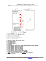
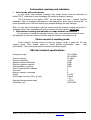
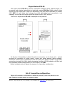
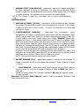
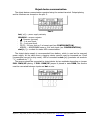
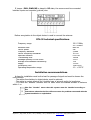
Individual security alarm system
Installation manual
2003
©Korteks
Zilupes st. 7, Riga, Latvia, Ph./fax: (+371)-7-505604, (+371)-7-505603 E-mail: [email protected], http://www.cortex.lv
General properties
The individual security alarm system consists of object device RT4-5I, an individual
receiver RR4-5m, power supply, antennas and is used for information transmission
about state of object device’s entries (security zones) and its visualization.
System also secure:
· A control of supply voltage and alarm signal transmission to receiver if will be it
decreasing
· System’s self-control using test signal transmitting from object device and
forming of alarm signal if will be lost some test signal.
· Receiver’s transmission of receiving information to “ open collector” outputs.
Delivery set
1.
2.
3.
4.
Object device RT4-5I – 1unit
Individual receiver RR4-5m – 1unit.
Antenna ST1-1 (*) - 2 unit
Power supply for receiver’s supply –1 unit (**)
* - if necessary could be set by another antenna types.
** - power supply for object device RT4-5I is not included to set and could be delivery
separately.
Individual Receiver RR4-5m
The individual receiver RR4-5m is used for information collection from object device
RT4-5I and it’s treatment.
RR4-5m secure:
· 8-message memory;
· Information receiving, LED and sound indication;
· Control for test messages from RT4-5I;
· “open collector” outputs for addition device’s connection.
RR4-5m working modes:
RR4-5m can work one of two modes:
1. Mode with confirmation
Of this mode necessary after each message receiving from object device RT4-5I
to confirm by push of button “RST” on the receiver’s front panel (see picture 1).
2. Mode without confirmation
Of this mode not necessary to confirm an each received massage. Sound
switching off happens automatically after 2s of message receiving. Received massage at
once is reflected on the receiver’s RR4-5m front panel.
©Korteks
Zilupes st. 7, Riga, Latvia, Ph./fax: (+371)-7-505604, (+371)-7-505603 E-mail: [email protected], http://www.cortex.lv
Indication and operating control.
RR4-5m form, operating control and indication is displayed on the picture 1.
Pict.1.
1. Supply indicator.
2. Lost communication with RT4-5I indicator.
3. Indicator of 1-st zone’s state.
4. Indicator of 2-nd zone’s state.
5. Indicator 3-th zone’s state indicator.
6. Indicator 4-th zone’s state.
7. Indicator of battery state of object device.
8. Confirmation button.
9. 12V battery minus “-“.
10. 12V battery plus “+“.
11. Common.
12. “open collector” output for lost communication with object device RT4-5I.
13. “open collector” output for 1-st zone.
14. “open collector” output for 2-nd zone.
15. “open collector” output for 3-rd zone.
16. “open collector” output for 4-th zone.
17. “open collector” output for object device battery
18. jumper for mode switching of receiver RR4-5m:
close – without confirmation mode; open – with confirmation .
19. antenna connector
©Korteks
Zilupes st. 7, Riga, Latvia, Ph./fax: (+371)-7-505604, (+371)-7-505603 E-mail: [email protected], http://www.cortex.lv
Information receiving and indication
1. In the mode with confirmation.
In this mode, each received message from object device must be confirmed by
button “RST”, otherwise all next messages will putted to receiver’s memory.
The first press on the button “RST” off the sound, the next – confirm received
messages. Each of message confirmation is accompanied by short sound; bet the last – a
thrice-repeated sound. Receiver before new message displays the last message.
Note: if a user don’t look though a receiver memory and the receiver receives more then 8
messages then a new massages will write to memory but the previous will be lost!
2. Information receiving and indication in mode without confirmation.
In this mode isn’t used the massage memory. Each new received message at once
will displayed on the front panel of receiver and will turned on the sound for 2s.
Choice receiver’s working mode.
Choice receiver working mode is chosen by jumper, which is placed on the rear
receiver panel. Close jumper accord to mode without confirmation, open – with
confirmation. The choice mode must be carried out without supply.
RR4-5m technical specifications.
Frequency range
Channel spacing
Receiver sensitivity
Adjacent channel selectivity
Spurious response reaction
Intermodulation response
Unit of object device’s address
Zone unit
Memory capacity, massages
Supply
Consumption current (12V), at most
Operating temperatures range
Dimension, mm
139-174MHz,
220-300MHz
12.5kHz
0,5uV
50dB
50dB
50dB
1
5
8
10-15V
150mA
+15 +35 С
155х70х25
©Korteks
Zilupes st. 7, Riga, Latvia, Ph./fax: (+371)-7-505604, (+371)-7-505603 E-mail: [email protected], http://www.cortex.lv
Object device RT4-5I.
The object device RT4-5I is used for information collection about guarded object, it’s
processing and wireless transmitting to individual receiver RR4-5m. Beside, object device
controls for own supply and in case of it decreasing (10V less) send information to receiver
(LED BAT). If input state don’t change long time will formed and transmitted a test
massage. In this case the receiver dives the signal and LED TEST will burn.
The form of object device RT4-5I is displayed on the picture 2.
pict. 2
On the top of transmitter is placed the antenna connector, on the lower part – contact
terminal for connection of power supply, sensor and object device’s status indicator.
Functional contact using is displayed on the front case part. Supply indicator is light after
connecting to supply line. After supply decreasing less then 10V the indicator will blink and
the transmitter send message about it to the receiver, LED BAT.
Behind of object device is placed the jumpers for transmitter configuration.
Set of transmitter configuration.
Setting of transmitter configuration is realized by jumpers, which are placed on rear
side. Function for each jumper is showed on label.
©Korteks
Zilupes st. 7, Riga, Latvia, Ph./fax: (+371)-7-505604, (+371)-7-505603 E-mail: [email protected], http://www.cortex.lv
1. NORMAL STATE (CON/DISCON) – determines, what kind of output state (open
or close) will have a normal for transmitter, but what will be alarming. If the
jumper is open then normal state will be accord to contact closing, but if it is close
– contact breaking. This operation must be carried out without supply.
NOTE. This jumper is used then transmitter has an input arming/disarming
(see.
CONFIGURATION).
2. WATCHDOG TIMER (24/12h) – determines, when will send the test massage
to receiver if the transmitter doesn’t have the changing on its inputs. If the jumper
is open this time will 25 hours; if close – 12 hours. This operation must be carried
out without supply.
3. CONFIGURATION (ARM/EQ) – determines the transmitter’s inputs
configuration. If jumper is opened then object device has one arm/disarm input
(ARM), one 24-hours zone’s input (ZP) and two inputs common using (Z1 and Z2).
If input ARM is open then object device has a mode “DISARM” (status LED
indicator isn’t burn). In this case a change in zones Z1 and Z2 is ignored. After
ARM input closing object device controls a state of zones Z1, Z2 and ZP. If one of
them has the alarm state the object device reports about this by blinking status
LED and don’t activate an arming state. Then Z1, Z2 and ZP inputs will normalize
the object device will active the arming state automatically (status LED isn’t burn)
In this mode the object device will react to anything zone’s changing.
If jumper is closed all inputs are equitable and the object device will react if is a
change in any zones. At the same time LED of corresponding zone displays closed
zone state on the receiver. Status LED isn’t used in this mode.
NOTE. This operation must be carried out without supply.
4. REPEAT NUMBER (3/6) – determines repeater’s quantity of one message. If
jumper is opened then the device repeats one message 3 times, if jumper is closed
– 6 times.
5.
PULL DWN/UP – determines which level must be on the object device’s
inputs in order to it will be as closed. If jumper is place in DWN state then an
input will
closed if it has a voltage 12V. If jumper is placed in UP state, an input will closed
if it has a ground.
Attention! The jumper PULL DWN/UP must be placed necessarily! Without it the
object device don’t work!
©Korteks
Zilupes st. 7, Riga, Latvia, Ph./fax: (+371)-7-505604, (+371)-7-505603 E-mail: [email protected], http://www.cortex.lv
Object device communication.
The object device communication operated using the contact terminal. Output placing
and its functions are showed on the pict. 3.
Рис.3.
·
·
·
·
·
bat.(+/-) – power supply contacts;
SENSORS – sensors contacts:
- Common (ground)
Z1 – 1-st zone input,
Z2 – 2-nd zone input,
ZP/Z3 – 24-hour zone or 3-rd zone input (see CONFIGURATION),
ARM/Z4 – ARM/DISARM zone or 4-th zone input (see CONFIGURATION);
stat.(+/-) – contact for status LED communication.
The object device supply is recommended from battery, which is used as the reserved
power supply. At the same time a charging device current must be increased per 15mA
(consumption current in duty mode). LED is connected to stat.(+/-) contacts: an anode to
"+", a cathode to "-" ().
The sensors should be connected to object device by two methods depending on jumper
PULL DWN/UP placing. If PULL DWN/UP jumper is placed in state DWN, the sensors
must be connected between inputs and bat.+ wire.
©Korteks
Zilupes st. 7, Riga, Latvia, Ph./fax: (+371)-7-505604, (+371)-7-505603 E-mail: [email protected], http://www.cortex.lv
If jumper i PULL DWN/UP is placed in UP state, the sensors must be connected
between inputs and common (ground) wire.
Before energization to the object device is need to connect the antenna.
RT4-5I technical specifications.
Frequency range
Emission class
Carrier power
Frequency deviation
Carrier frequency fluctuation
Spurious emission
Transmitting time
Message quantity for one event
Average time between transmitting
Supply
Dimensions, mm
Operating temperature range
139 -174MHz,
220 -300MHz
8K0F1D
5W
2,5kHz
-6
10 10
0.25 W
150ms
3 or 6
1.2s
11-14V
155х70х25
-10 - +50 С
Installation recommendations.
A place for installation must be the best for passage of signal and must be known the
next moment:
- The cables from battery to object device must be minimal;
- The cables to contact terminal don’t installed near of antenna and/or its lengthwise;
- If is used the “doublet” antenna then its cable must be installed athwart of antenna
within 1 m.
!!!
The firm “Korteks” warns that this system must be installed according to
this
instructions otherwise the firm will not account for problems connected whit the
system installation or exploitation.
©Korteks
Zilupes st. 7, Riga, Latvia, Ph./fax: (+371)-7-505604, (+371)-7-505603 E-mail: [email protected], http://www.cortex.lv