1
2D-MESH GENERATORS
CM2 TRIAMESH & CM2 QUADMESH
CM2 TRIAMESH ANISO &
CM2 QUADMESH ANISO
Series 4.6.x
TUTORIAL
AND
USER'S MANUAL
Computing Objects
25 rue du Maréchal Foch, F-78000 Versailles.
www.computing-objects.com
Revision of manual: October 2015
CM2 TriaMesh & QuadMesh – CM2 TriaMesh Aniso & QuadMesh Aniso - V 4.6
I – OVERVIEW OF THE MATH1 LIBRARY
Variable-size containers and fixed-size containers
8
Views of the variable-size containers
9
Fixed-size containers
10
STL-like iterators and the generic math library
10
Bound checking
11
Interoperability with other math containers
11
II – TUTORIAL
15
II-1 GETTING STARTED – A SIMPLE SQUARE
17
II-2 SQUARE WITH AN INTERNAL LINE
27
II-3 SQUARE WITH INTERNAL HOLES
31
II-4 SQUARE WITH GRADING MESH SIZE
33
II-5 SQUARE WITH AN INTERNAL HARD NODE
35
II-6 MULTIPLE MESHES
37
II-7 SHARED BOUNDARIES
41
II-8 BACKGROUND MESH
47
II-9 ANISOTROPIC MESHES
53
II-10 3-D SURFACE MESHES (ANISO MESHERS ONLY)
59
III – USER'S MANUAL
71
III-1 MESH GENERATORS’ DATA
2
7
73
Coordinates of the points
73
Hard edges
73
Isolated hard nodes
73
Repulsive points
74
Background mesh
74
Metric field
74
Elements
75
Unenforced entities
75
Pathological boundaries
75
Elements’ color
76
Neighbors
76
Ancestors
76
Shape qualities
76
Histograms
77
Copyright Computing Objects – October 2015
CM2 TriaMesh & QuadMesh – CM2 TriaMesh Aniso & QuadMesh Aniso - V 4.6
Errors and warnings
77
Complementary information
77
III-2 ERROR AND WARNING CODES
81
Error codes
81
Warning codes
83
III-3 OPTIONS OF THE MESH GENERATORS
85
Basic operating mode
85
Strict constraints enforcement
85
Keeping or removing internal holes
85
All-quad or quad-dominant mode (CM2 QuadMesh & CM2 QuadMesh Aniso)
86
Refinement
86
Recomputing the boundary edges
87
Node smoothing
87
Node inserting
87
Node removing
87
Shell remeshing
88
Avoiding clamped edges (CM2 TriaMesh & CM2 TriaMesh Aniso)
88
Computation of the size-qualities histogram
88
Pattern for structured meshes (CM2 TriaMesh & CM2 TriaMesh Aniso)
88
Pattern for structured meshes (CM2 QuadMesh & CM2 QuadMesh Aniso)
88
Multi-structured subdomains
89
Limit on the number of nodes
89
Optimization level
89
Target metric
89
Max gradation
89
Weight on shape quality
90
Weight on quadrangles (CM2 QuadMesh & CM2 QuadMesh Aniso)
90
Minimum quad quality (CM2 QuadMesh & CM2 QuadMesh Aniso)
90
Upper bound on edges length
90
Display handler
90
Interrupt handler
91
III-4 GENERAL SCHEME OF THE GENERATORS
Copyright Computing Objects – October 2015
97
3
CM2 TriaMesh & QuadMesh – CM2 TriaMesh Aniso & QuadMesh Aniso - V 4.6
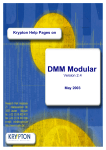
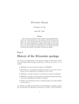
Figures
Figure 1 – Views and data in variable-sized vectors.
Figure 2 – Triangle mesh of a square.
Figure 3 – Print info for the square example.
Figure 4 – Histogram of the size-qualities of all the edges in the square example.
Figure 5 – Square meshed with quads.
Figure 6 – Square with internal line (T3 and all-Q4).
Figure 7 – Square with internal line (quad-dominant mode).
Figure 8 – Square with a hole (T3 and all-Q4).
Figure 9 – Concentric circles with alternate rotation sign (T3 and all-Q4).
Figure 10 – Meshes with grading size (T3 and all-Q4).
Figure 11 – Mesh concentration near a hard node (T3 and all-Q4).
Figure 12 – Multiple meshes (T3 and all-Q4). The four domains are meshed simultaneously.
Figure 13 – Domain composed of three attached subdomains.
Figure 14 – Example with shared boundaries (T3 and all-Q4).
Figure 15 – Example of ambiguous orientation of an inner contour.
Figure 16 – Hole adjacent to the external contour.
Figure 17 – Hole adjacent to the external contour (T3 and Q4).
Figure 18 – Use of a background mesh to support a sizes field on the domain (T3 and all-Q4).
Figure 19 – The background mesh used in the previous example.
Figure 20 – Background mesh covering only a fraction of the domain.
Figure 21 – Background meshes for both the boundary and the domain (T3 and all-Q4).
Figure 22 – A single scalar defines an isotropic metric. A 2D-anisotropic metric needs two vectors.
Figure 23 – Definition and storage of the 2-D anisotropic metrics.
Figure 24 – Anisotropic meshes (T3 and Q4).
Figure 25 – 2-D anisotropic meshes (T3 and all-Q4).
Figure 26 – 2-D anisotropic meshes (T3 and all-Q4).
Figure 27 – Definition and storage of the 3-D anisotropic metrics.
Figure 28 – Mapping between the reference space and the surface.
Figure 29 – 2-D anisotropic meshes in the reference space.
Figure 30 – Surface meshes obtained via an anisotropic mesh in the reference space.
Figure 31 – 2-D anisotropic meshes in the reference space.
Figure 32 – 3-D surface meshes (T3 and all Q4).
Figure 33 – Nodes and edges local numbering in triangles and quads.
Figure 34 – Mode "refine_flag = false" (T3 and Q4) for the example II-3.
Figure 35 – General scheme of the mesh generators.
9
18
21
23
25
28
30
31
32
34
36
37
41
43
44
44
45
49
49
50
52
53
53
55
57
58
61
62
66
66
69
69
75
87
97
Tables
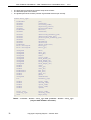
Table 1 – Vectors and matrices exported by the math1 library.
Table 2 – triamesh::mesher::data_type and quadmesh::mesher::data_type.
Table 3 – triamesh_aniso::mesher::data_type and
quadmesh_aniso::mesher::data_type.
Table 4 – Error codes for CM2 TriaMesh and CM2 TriaMesh Aniso.
Table 5 – Error codes for CM2 QuadMesh and CM2 QuadMesh Aniso.
Table 6 – Error codes.
Table 7 – Warning codes for all meshers.
Table 8 – Warning codes.
Table 9 – Effects of the strict_constraints_flag on invalid constraints.
Table 10 – triamesh::operating_mode_type.
Table 11 – triamesh_aniso::operating_mode_type.
Table 12 – quadmesh::operating_mode_type.
Table 13 – quadmesh_aniso::operating_mode_type.
4
Copyright Computing Objects – October 2015
9
78
79
81
81
82
83
83
86
93
94
95
96
CM2 TriaMesh & QuadMesh – CM2 TriaMesh Aniso & QuadMesh Aniso - V 4.6
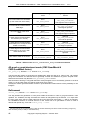
This manual describes the 2-D mesh generators of the CM2 MeshTools library: the isotropic meshers
CM2 TriaMesh and CM2 QuadMesh, and the anisotropic meshers CM2 TriaMesh Aniso and
CM2 QuadMesh Aniso. Cases of 3-D surface mesh using the anisotropic meshers are also presented.
All these mesh generators are constrained unstructured meshers: the boundary mesh (contour mesh)
as well as the internal hard edges and hard points (embedded) are kept unmodified in the final mesh.
Based on a fast and robust hybrid "Advancing-Front and Delaunay" algorithm, they generate high
quality elements with smooth grading size according to the length of the boundary edges or to the userspecified sizes. The speed is near independent of the number of the elements to be generated.
Option switches can be used to adapt the meshers to the various needs of the user concerning mesh
generation, refinement and optimization (they can also be used as optimizers-only of some already
existing meshes).
The quad meshers can generate all-quad meshes (the default) or mixed quad-dominant meshes. In the
all-quad mode, the number of edges in each segment must be even. This condition can be easily
respected using the functions of CM2 Meshtools1D. However, when parity is not suitable or even
impossible to achieve, the quad-dominant mode must be activated and user must accept some
triangles in the final mesh.
Many data concerning the mesh are available upon exit: shape and size qualities histograms, matrix of
the neighbors, number of subdomains, meshed surface...
Like all the other meshers of the library, CM2 TriaMesh, CM2 QuadMesh, CM2 TriaMesh Aniso and
CM2 QuadMesh Aniso are thread-safe (several instances or the meshers can be ran concurrently).
The math1 library exports the vector and matrix classes needed to communicate with the meshers.
The additional libraries meshtools, meshtools1d, meshtools2d and meshtools3D can be used to
generate simple 1-D meshes for the boundaries or to do some mesh transformations (translation,
rotations, concatenation, merging...)
For maximum performance, these software components are developed using the standard C++
language with efficient object-oriented programming techniques.
The full sources are available and they have been ported to most major platforms.
With a binary license, these libraries are shipped as precompiled dynamic libraries - DLL Win32 or
shared Linux i386 - with .lib and C++ headers files.
The source code of CM2 MeshTools (full library) has been registered with the APP under Inter Deposit
number IDDN.FR.001.260002.00.R.P.1998.000.20700 (22/06/1998) and
IDDN.FR.001.250030.00.S.P.1999.000.20700 (16/06/1999) is regularly deposited since then.
The source code specific to CM2 TriaMesh, together with this manual, has been registered with the
APP under Inter Deposit number IDDN.FR.001.440021.000.R.P.2008.000.20700 (31/10/2008) and is
regularly deposited since then.
The source code specific to CM2 QuadMesh, together with this manual, has been registered with the
APP under Inter Deposit number IDDN.FR.001.440020.000.R.P.2008.000.20700 (31/10/2008) and is
regularly deposited since then.
Copyright Computing Objects – October 2015
5
CM2 TriaMesh & QuadMesh – CM2 TriaMesh Aniso & QuadMesh Aniso - V 4.6
6
Copyright Computing Objects – October 2015
CM2 TriaMesh & QuadMesh – CM2 TriaMesh Aniso & QuadMesh Aniso - V 4.6
I – OVERVIEW OF THE MATH1
LIBRARY
Copyright Computing Objects – October 2015
7
CM2 TriaMesh & QuadMesh – CM2 TriaMesh Aniso & QuadMesh Aniso - V 4.6
Before digging into the meshers, let us have a look into the math1 library which exports the types of
vector and matrix used by the meshers. We do not intend here to give a full description of this math1
library, nor the associated template libraries vecscal, vecvec, matscal, matvec, and matmat. We
will simply explain the basic traits of these math classes in order to use the meshers properly. A full
description can be found in the math1 API1.
The math1 library exports 16 types of vector, 14 types of rectangular matrix and 8 types of symmetric
matrix2.
They can be divided into two main categories: the variable-size containers, such as DoubleVec,
DoubleMat, or DoubleSym, and the fixed-size containers, such as DoubleVec3, DoubleMat2x2 or
DoubleSym2.
Following the C usage, all these math containers are zero based: a vector with size N extends from
index 0 to N-1.
Variable-size containers and fixed-size containers
Besides the fact that only the containers of the first category can be resized - automatically or manually
- they differ by the way the copy constructors and the copy operators work. The variable-size containers
are merely views to data arrays, whereas the fixed-size containers actually hold the data as a member.
The first category only holds a reference, and a copy implies only a copy of that reference, not the data
(shallow copy). A copy of a container of the second category actually copies the data (deep copy).
Example:
DoubleVec
DoubleVec
V1;
V2(10, +1.0);
// Empty vector.
// Vector of 10 values, all intitialized to 1.0
V1.push_back (3.0)
V1.push_back (2.0)
// V1.size() == 1
// V1.size() == 2
V1 = V2;
// Shallow copy3 (V1.size() == 10).
// Previous values of V1 are lost (3.0 and 2.0).
V1[0] = 0.0;
V2.clear();
//
//
//
//
V2[0] == 0.0 (because the data are shared).
V2.size() == 0 but V1.size() == 10
The data are not deleted because still viewed
from V1.
1math1.html
or math1.chm.
Some other types are defined but not exported (they cannot be exchanged between dynamic libraries, only
between statically linked entities): vector_fixed<T,N>, matrix_fixed<T,M,N>, dense1D<T>, dense2D<T>
and symmetric_full<T>.
3 A deep copy can be obtained with the template function vecvec::copy :
V1.resize (V2.size());
// Resize V1 to V2.size().
vecvec::copy (V2, V1);
// Copy all V2 values into V1.
or with the "copy" member:
V1.copy (V2);
// Resize V1 to V2.size() and copies the data.
2
8
Copyright Computing Objects – October 2015
CM2 TriaMesh & QuadMesh – CM2 TriaMesh Aniso & QuadMesh Aniso - V 4.6
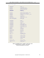
Vectors
Rectangular matrices
Symmetric matrices
DoubleVec
DoubleMat
DoubleSymMat
FloatVec
FloatMat
FloatSymMat
IntVec
IntMat
IntSym
UIntVec
UIntMat
UIntSym
DoubleVec3
DoubleMat3x1
DoubleSym2
DoubleVec4
DoubleMat2x2
DoubleVec6
DoubleMat3x2
DoubleMat2x3
DoubleVec2
DoubleSym3
DoubleVec8
DoubleVec9
DoubleMat3x3
UIntVec2
UIntVec3
UIntMat3x1
UIntVec4
UIntMat2x2
UIntVec6
UIntMat3x2
UIntMat2x3
UIntSym2
UIntSym3
UIntVec8
UIntVec9
UIntMat3x3
Table 1 – Vectors and matrices exported by the math1 library.
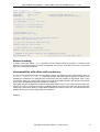
Views of the variable-size containers
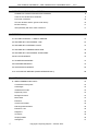
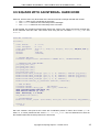
Several variable-sized containers can have a view on the same array of data, but the view can be
different from each other. The beginning and the size in the array are specific to each container. For
instance in an array of 30 items, a first vector views items from 0 to 9 and a second one views items
from 5 to 20.
beg = 0
size = 10
data
beg = 5
size = 16
data
Data array
Figure 1 – Views and data in variable-sized vectors.
Elements from 5 to 9 are accessible from the two vectors.
When a destructor is called on a variable-size container, the data are destroyed only when no other
container shares them anymore. A smart pointer mechanism is used to count the number of references
on the data and the deallocation actually occurs when the count reaches null. The memory
management is automatic (automatic garbage collection).
Copyright Computing Objects – October 2015
9
CM2 TriaMesh & QuadMesh – CM2 TriaMesh Aniso & QuadMesh Aniso - V 4.6
Example:
DoubleVec
DoubleVec
*V1 = new DoubleVec(10, -1.0);
*V2 = new DoubleVec(*V1);
// Shallow copy (share the data).
delete V1;
delete V2;
// The data are still referenced by V2.
// Now the data are destroyed too.
Fixed-size containers
The fixed-size math containers are deep-copy containers. The copy-constructor and the copy-operator
do not make the data to be shared anymore but leads to actually different arrays in memory. They are
simpler than the variable-size containers, and faster for short arrays, whereas the variable-size
containers are more suited for big arrays.
Example:
DoubleVec2
DoubleVec2
V1;
V2(+1.0);
// Vector of 2 unintitialized values (double).
// Vector of 2 values intitialized to 1.0
V1[0] = 0.0;
V1[1] = -1.0;
V1 = V2;
V2[0] = 0.0;
V1[1] = 0.0;
// Deep copy: V1 = {1, 1}, V2 = {1, 1}.
// V1 = {1, 1}, V2 = {0, 1}
// V1 = {1, 0}, V2 = {0, 1}
STL-like iterators and the generic math library
All these math containers are optimized for numerical computation.
The vector containers - variable-size and fixed-size - are equipped with STL-like iterators begin() and
end(), to make them compatible with most of the STL algorithms. They also have access operators
such as operator[], and the usual functions for a vector class: size(), empty(), front(),
back()...
The variable-size vectors are also equipped with members such as reserve, resize, push_back,
and pop_back.
Aside from the STL algorithms, one can also use the math-specific template functions of the vecscal,
vecvec, matscal, matvec and matmat libraries (cf. math1 API).
Example:
DoubleVec
DoubleMat
V1(3), V2(3,-1.0);
M(3, 10, 0.0);
vecvec::copy (V2, V1);
vecvec::axpy (2.0, V1, V2);
vecscal::mult (-1.0, V1);
// Matrix of doubles 3 by 10 set to 0.
// Hard copy of V2 into V1 (sizes match).
// V2 += 2 * V1
// V1 = -V1
The variable-size matrix types (DoubleMat, IntMat and UIntMat) have a behavior similar to the
vectors with respect to the memory management and the copy operators (and the copy-constructors).
In addition, the rows and the columns are equipped with iterators, just like the vectors, and the same
template functions can be used on them.
Example:
10
Copyright Computing Objects – October 2015
CM2 TriaMesh & QuadMesh – CM2 TriaMesh Aniso & QuadMesh Aniso - V 4.6
const unsigned
const double
DoubleMat
DoubleVec2
N = 10;
PI = 3.14159;
pos(2, N);
V;
// Uninitialized 2xN matrix.
// Uninitialized vector of size 2.
// Points on a circle.
for (unsigned j = 0; j < N; ++j)
{
pos(0,j) = ::cos(j*2*PI/N);
pos(1,j) = ::sin(j*2*PI/N);
}
// Set radius to 3.0
matscal::mult (3.0, pos);
// Copy column #2 to V (ok, dimensions match).
vecvec::copy (pos.col(2), V);
// Copy V to column #9 (the last one).
vecvec::copy (V, pos.col(9));
// Copy column #9 to column #0
vecvec::copy (pos.col(9), pos.col(0));
// Append V in a new column of pos (dimensions match).
pos.push_back (V);
// pos.cols() == 11 after this line.
Bound checking
In debug mode (with macro _DEBUG defined), bound violations abort the program. In release mode
however, for best performance no check is performed and the user must take care not to out value the
limits of the vectors and matrices.
Interoperability with other math containers
The API of the MeshTools library use exclusively vectors and matrices of the math1 library (such as
DoubleMat, UIntMat, FloatVec...). To use the meshers with other types of vectors and matrices, the
variable-size containers are equipped with constructors with raw pointers as arguments. Hence, they
can view the data in any other math containers as long as the latter provide a way to get a raw pointer
to their data, and that these data are contiguous in memory.
Remember that the variable-size containers implement shallow copies. This means that the arrays are
shared, not copied. Therefore the memory management becomes a point to take care of and the user
must keep in mind which library is responsible for deleting the memory upon exit. The default is that the
allocator of the array remains responsible for its deletion.
Example:
Copyright Computing Objects – October 2015
11
CM2 TriaMesh & QuadMesh – CM2 TriaMesh Aniso & QuadMesh Aniso - V 4.6
double
double*
std::vector<double>
DoubleVec
DoubleVec
DoubleVec
buff1[100];
buff2 = new double[100];
buff3(100);
// Static raw C array.
// Dynamic raw C array.
// STL vector.
V1(50, buff1);
// Views the first 50 elements in buff1.
V2(50, buff2);
// Views the first 50 elements in buff2.
V3(50, buff3.begin()); // Views the first 50 elements in buff3.
V2.clear();
V2 = V1;
V3.clear();
delete[] buff2;
//
//
//
//
//
//
//
buff3.clear();
buff2 is not deallocated.
buff2 is not deallocated.
buff3 is not deallocated.
Dangerous but correct because buff2 is no longer
referenced by any DoubleVec.
Dangerous: data in buff3 may have been deallocated.
Don't use V3 anymore.
Note that this can be done with the fixed-size containers of math1:
DoubleVec3
DoubleVec
V3(1.0, 0.0, -1.0);
V(3, V1.begin());
// Views the elements in V3.
The matrices of math1 can view also the data in an external container. In addition to the raw pointer to
the data, the user must provide the number of rows, the number of columns and the stride between two
columns (so-called leading dimension):
unsigned*
UIntMat
buff = new unsigned[30];
M(3, 10, /*ld=>*/ 3, buff);
As before, the matrix is not responsible for the deletion of the underlying buffer4.
In the case where a container constructed this way is subsequently resized, it may "point" to another
array of memory but the initial buffer remains valid:
double*
DoubleVec
buff = new double[6];
V(5, buff);
V.push_back (2.0);
V.clear_hard();
//
//
//
//
Reallocation and copy performed.
buff is still alive, but V does not "point" to
it anymore.
The new array of V is deallocated, not buff.
As a rule of thumb, the lifetime of the external buffer must span the lifetime of the math1 container.
double*
buff = new double[6];
{
}
DoubleVec
V(5, buff);
...
// Use V here.
// V is killed here but the buffer is spared.
delete[] buff;
// So long with buff.
We have seen how to construct math1 variable-size container upon other containers or buffers. To do
the other way, we use the data() or begin() members to access the underlying data:
Example:
4
A default parameter "protect" in the constructors can be used to change this behaviour.
12
Copyright Computing Objects – October 2015
CM2 TriaMesh & QuadMesh – CM2 TriaMesh Aniso & QuadMesh Aniso - V 4.6
DoubleVec
double*
unsigned
V(50, 0.0);
buff = V.data();
N
= V.size();
// Equals to 50
for (unsigned i = 0; i < N; ++i, ++buff)
*buff = double(i);
assert (V[10] == 10.);
// Changes in buff have been seen in V.
DoubleMat
double*
unsigned
unsigned
unsigned
// Equals to 3
// Equals to 40
// Equals to 3 (here stride == rows).
P(3,
buff
M
N
LD
40);
= P.data();
= P.rows();
= P.cols();
= P.ld();
for (unsigned j = 0; j < N; ++j)
for (unsigned i = 0; i < M; ++i)
buff[i + j*LD] = double(i + j*LD);
assert (P(0,10) == 30.);
// Changes in buff have been seen in P.
Here, the math1 vectors and matrices are responsible for the deletion of their data:
DoubleMat
double*
P(3, 40);
buff = P.data();
delete[] buff;
P.resize (3, 80);
// Don't do that !
// Crash now, or maybe later...
Copyright Computing Objects – October 2015
13
CM2 TriaMesh & QuadMesh – CM2 TriaMesh Aniso & QuadMesh Aniso - V 4.6
14
Copyright Computing Objects – October 2015
CM2 TriaMesh & QuadMesh – CM2 TriaMesh Aniso & QuadMesh Aniso - V 4.6
II – TUTORIAL
Copyright Computing Objects – October 2015
15
CM2 TriaMesh & QuadMesh – CM2 TriaMesh Aniso & QuadMesh Aniso - V 4.6
Before meshing a 2-D domain, the first step is to generate a 1-D mesh of the external contour. This
chapter mostly details cases where the boundary mesh is obtained using some simple CM2 MeshTools
functions. One example illustrates the case where the boundary mesh has been generated by other
means and is simply read from a file.
Each example starts with including the file stdafx.h (can be a precompiled header), giving access to
the classes and the functions of the library (API).
The general namespace cm2 has nested namespaces such as vecscal, vecvec, meshtools or
triamesh. The user can add “using namespace” directives in this stdafx.h. Keeping namespaces in
the user’s source code can however be useful to improve the legibility and to avoid name conflicts.
File "stdafx.h" 5:
// MESHTOOLS
#include "meshtools.h"
#include "meshtools1d.h"
// General purpose mesh routines
// To generate 1D meshes
// MESHERS
#include "triamesh.h"
#include "quadmesh.h"
// TriaMesh mesher
// QuadMesh mesher
using namespace cm2;
// Main cm2 namespace can now be omitted.
Required libraries6:
cm2math1
cm2misc
cm2meshtools
cm2meshtools1d
cm2meshtools2d
cm2triamesh
cm2quadmesh
5
If neither meshtools nor CM2 QuadMesh is used, the file "stdafx.h" can reduce simply to:
#include "triamesh.h"
and the required libraries are cm2math1, cm2misc, cm2meshtools, cm2meshtools2d and cm2triamesh
6 On Windows, the lib names currently end with _Win32_45 or _x64_45. For instance cm2math1_x64_45.dll.
On Windows, file extensions for the libraries are .lib and .dll. On Linux/Unix/Mac OS platforms, file extensions are
usually .a (static archive), .so or .dylib (dynamic lib).
16
Copyright Computing Objects – October 2015
CM2 TriaMesh & QuadMesh – CM2 TriaMesh Aniso & QuadMesh Aniso - V 4.6
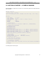
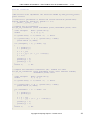
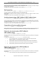
II-1 GETTING STARTED – A SIMPLE SQUARE
This first example is a regular mesh of a square. The four boundary segments are equally discretized
with 10 elements.
#include "stdafx.h"
// Display handler (optional).
static void display_hdl (void*, unsigned, const char* msg) { cout << msg; }
int main()
{
const double
const unsigned
const DoubleVec2
DoubleMat
UIntVec
UIntMat
L = 10.0;
N = 10;
P0(0.,0.), P1(L,0.), P2(L,L), P3(0.,L);
pos;
indices;
connectB;
// UNLOCK THE DLL.
triamesh::registration ("Licensed to SMART Inc.", "F53EA108BCWX");
// VERTICES AND LINE MESHES.
pos.push_back (P0);
pos.push_back (P1);
pos.push_back (P2);
pos.push_back (P3);
meshtools1d::mesh_straight (pos, 0, 1, N, indices); indices.pop_back();
meshtools1d::mesh_straight (pos, 1, 2, N, indices); indices.pop_back();
meshtools1d::mesh_straight (pos, 2, 3, N, indices); indices.pop_back();
meshtools1d::mesh_straight (pos, 3, 0, N, indices);
meshtools1d::indices_to_connectE2 (indices, connectB);
// THE 2D MESH.
triamesh::mesher
triamesh::mesher::data_type
the_mesher.run (data);
the_mesher;
data (pos, connectB);
// SOME OUTPUT INFO (OPTIONAL).
data.print_info (&display_hdl);
// VISUALISATION (OPTIONAL).
meshtools::medit_output ("out.mesh", data.pos, data.connectM, CM2_FACET3);
}
return 0;
// main
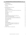
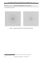
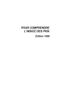
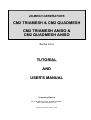
The resulting mesh is shown Figure 2.
Copyright Computing Objects – October 2015
17
CM2 TriaMesh & QuadMesh – CM2 TriaMesh Aniso & QuadMesh Aniso - V 4.6
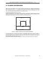
Figure 2 – Triangle mesh of a square.
Let us explain this program line by line.
Authorization of the library
The libraries triamesh and quadmesh are protected and need to be unlocked with a call to
triamesh::registration or quadmesh::registration. Two strings must be provided for each
library: the name of your company or organization that has acquired the license and a secret code contact [email protected] for any licensing enquiry. Note that both strings are case
sensitive and the registration call must be made each time the library is loaded into memory and before
any run of the mesher.
triamesh::registration ("Licensed to SMART Inc.", "F53EA108BCWX");
Contour mesh
This is usually the heaviest part of the work for the user. In this example, we use only routines from the
MeshTools libraries but the user is free to generate this contour mesh with any other tool or even to
read it form a file7. Anyway, the 2-D meshers need this contour mesh as a couple of matrices: the
matrix pos containing the points’ coordinates and the connectivity matrix connectB of the boundary
edges.
First, the corners of the square are created as four pair of coordinates in the pos matrix:
pos.push_back
pos.push_back
pos.push_back
pos.push_back
7
(P0);
(P1);
(P2);
(P3);
See example II-5.
18
Copyright Computing Objects – October 2015
CM2 TriaMesh & QuadMesh – CM2 TriaMesh Aniso & QuadMesh Aniso - V 4.6
The push_back function appends a new column at the end of a matrix. The size of the column must
match the current number of rows of the matrix. If the matrix is empty, the first vector sets this number
of rows.
After these four push-backs, the dimensions of the pos matrix are 2x4.
Now that the four corners are present, we can create the points in between and the associated edges:
meshtools1d::mesh_straight
meshtools1d::mesh_straight
meshtools1d::mesh_straight
meshtools1d::mesh_straight
(pos,
(pos,
(pos,
(pos,
0,
1,
2,
3,
1,
2,
3,
0,
N,
N,
N,
N,
indices); indices.pop_back();
indices); indices.pop_back();
indices); indices.pop_back();
indices);
The mesh_straight routine of the meshtools1d library generates N-1 new points equally spaced
into new appended columns in the pos matrix:
meshtools1d::mesh_straight
(DoubleMat& pos, unsigned i0, unsigned i1, unsigned N, UIntVec& indices);
The index of each point, i.e. the column in matrix pos, is also appended to the vector indices. With
i0 = 0 and i1 = 1, this vector contains upon exit of this function:
[0 4 5 6 7 8 9 10 11 12 1]
And the matrix pos is now of size 2x13:
0 1 2 3 4
Four corners
12
New generated nodes: #4 to #12
The last value in the indices vector, i.e. value 1, must be suppressed to avoid having it twice:
indices.pop_back();
The second call to mesh_straight with i0 = 1 and i1 = 2 sets the indices vector to:
[0 4 5 6 7 8 9 10 11 12 1 13 14 15 16 17 18 19 20 21 2]
After the four line meshes, the matrix pos is of size 2x40 and the indices vector has 41 values - the
last index equals to the first, here zero, to indicate that the contour is closed8.
The vector of indices is used to create the connectivity matrix of the boundary mesh:
8
The same result could have been achieved with:
UIntVec
hard_nodes(5);
hard_nodes[0] = 0;
hard_nodes[1] = 1;
hard_nodes[2] = 2;
hard_nodes[3] = 3;
hard_nodes[4] = 0;
meshtools1d::mesh_straight (pos, hard_nodes, 4*N, indices);
This variant of mesh_straight meshes a polyline going through some constrained points (hard_nodes)
Copyright Computing Objects – October 2015
19
CM2 TriaMesh & QuadMesh – CM2 TriaMesh Aniso & QuadMesh Aniso - V 4.6
meshtools1d::indices_to_connectE2 (indices, connectB);
The connectB matrix has now dimensions 2x40:
2x40 [0 4 5 6 7 ... 39
4 5 6 7 8 ... 0]
Now we have done the boundary mesh, all we have to do is to call the 2-D mesher. This done by
creating a data structure holding this 1D mesh and make the mesher run on it:
triamesh::mesher::data_type
the_mesher.run (data);
data (pos, connectB);
Upon exit, the matrix data.pos is bigger and contains all the new points generated inside the square
by the 2-D mesher. These new points are appended to the original matrix. The initial 40 points are still
untouched in the first 40 columns.
The connectivity of the final mesh is stored in the matrix data.connectM, each column storing the
indices of the nodes for an element9. connectM(i,j) is the ith local node of the jth element.
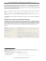
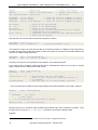
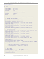
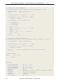
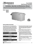
Printed information about the generated mesh and a MEDIT10 output file are obtained with:
data.print_info (&display_hdl);
meshtools::medit_output ("out.mesh", data.pos, data.connectM, CM2_FACET3);
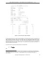
Here is the output given by data.print_info (&display_hdl):
9
The elements are always oriented counter-clock wise (director up)
MEDIT is a free vizualisation program (http://www.ann.jussieu.fr/~frey/logiciels/medit.html). Other output formats
are: Ensight, FEMAP (neutral), Nastran, STL, VTK and Wavefront OBJ.
10
20
Copyright Computing Objects – October 2015
CM2 TriaMesh & QuadMesh – CM2 TriaMesh Aniso & QuadMesh Aniso - V 4.6
***************************************
************* CM2 TRIAMESH ************
***************************************
Version
: 4.6.0.0
Hard nodes
: 40 (40 in)
Hard edges
: 40 (40 in)
Nodes
: 132
Triangles
: 222
Subdomains
: 1
Area
: 1.600000E+001
Qmin
: 8.374821E-001
Front time
: 0.00 s
Refine time
: 0.00 s
Optim time
: 0.00 s
Total time
: 0.00 s (INF t/s)
************ HISTOGRAM QS ************
Total number of bins
:
11
Total number of counts
:
222
Number of larger values :
0
Number of smaller values :
0
V max
: 9.990807E-001
V mean
: 9.462349E-001
V min
: 8.374821E-001
Bin number
10
9
8
7
6
5
4
3
2
1
0
-- Bin boundaries -0.90
0.80
0.70
0.60
0.50
0.40
0.30
0.20
0.10
0.01
0.00
1.00
0.90
0.80
0.70
0.60
0.50
0.40
0.30
0.20
0.10
0.01
Hits
167
55
0
0
0
0
0
0
0
0
0
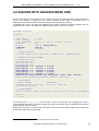
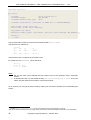
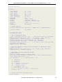
Figure 3 – Print info for the square example.
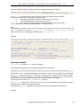
The generated mesh has 132 nodes and 222 triangles, for an initial contour mesh of 40 nodes and 40
edges (hard nodes and hard edges). The times spent in the three steps of the meshing process (front,
refine, optimize) are given in seconds11. The front mesh is the triangulation mesh with only the
boundary hard nodes. In the second step, new nodes are generated inside the domain to get elements
with good shape and size. Finally, the last step is for geometrical and topological optimizations to
improve the quality of the elements.
The formula used to compute the shape quality of a triangle writes:
Qs = 4 3
S
Lmax P
with:
11
Here the times are below 0.01 s. All runs are done with x64 CM2 libs (VS 2010 MD build) on Windows® 8 x64
with Intel® Xeon® E3-1270 V2 3.5 GHz (1 thread, turbo boost disabled). The typical speed with default settings on
such a platform ranges from 10 000 quads / s. (CM2 QuadMesh Aniso) to more than 300 000 triangles / s.
(CM2 TriaMesh).
Copyright Computing Objects – October 2015
21
CM2 TriaMesh & QuadMesh – CM2 TriaMesh Aniso & QuadMesh Aniso - V 4.6
S
Lmax
P
Area of the triangle.
Length of the longest edge of the triangle.
Perimeter of the triangle
This quality measure ranges from 0 for a degenerated triangle, to 1 for an equilateral triangle.
On the square example, the worst shape quality is 0.83 and the average is 0.94.
The size quality is also an important parameter to take into account. The size quality of an edge is a
measure based upon its actual length and the target size values defined at its two vertices. A size
quality of one indicates that the edge has the optimal length. A too short edge has a size quality lesser
than one - but always positive -, and a too long edge has a size quality greater than one. For instance,
an edge with a quality of two is twice as long as it should be.
The formula used to compute the length quality of an edge AB writes:
QhAB = L AB
h
ln A
hB
h A − hB
with:
L AB
hA
hB
Actual length of edge AB.
Target size at node A (expected edge length at A).
Target size at node B (expected edge length at B).
Let’s introduce also at this point the h-shock measure of an edge:
1
hs AB
h A hB QhAB
= min ,
−1
hB h A
These two measures are dimensionless and positive.
When
h A = hB the h-shock is null and the length quality simply writes QhAB =
AB
When Q h
and
LAB
.
hA
= 1 edge AB is considered having optimal length with repect to its target mesh sizes h A
hB .
To optimize a mesh we need to improve simultaneously both the shape quality of the elements and the
size quality of the edges. Unfortunately, these two targets are often contradictory.
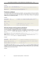
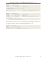
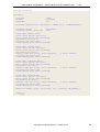
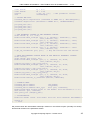
The histogram of the size qualities can be computed either inside the mesher by raising the flag
mode.compute_Qh_flag12 before meshing or with a posteriori call to the auxiliary function
meshtools::edge_qualities.
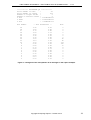
On the square example, the size qualities are well centered on the value 1 with a small variance:
12
See § III-3 for full description of the options of the meshers.
22
Copyright Computing Objects – October 2015
CM2 TriaMesh & QuadMesh – CM2 TriaMesh Aniso & QuadMesh Aniso - V 4.6
************ HISTOGRAM QH ************
Total number of bins
:
20
Total number of counts
:
353
Number of larger values :
0
Number of smaller values :
0
V max
: 1.284916E+000
V mean
: 1.021125E+000
V min
: 7.444225E-001
Bin number
19
18
17
16
15
14
13
12
11
10
9
8
7
6
5
4
3
2
1
0
-- Bin boundaries -1.90
1.80
1.70
1.60
1.50
1.40
1.30
1.20
1.10
1.00
0.90
0.80
0.70
0.60
0.50
0.40
0.30
0.20
0.10
0.00
2.00
1.90
1.80
1.70
1.60
1.50
1.40
1.30
1.20
1.10
1.00
0.90
0.80
0.70
0.60
0.50
0.40
0.30
0.20
0.10
Hits
0
0
0
0
0
0
0
16
36
174
102
17
8
0
0
0
0
0
0
0
Figure 4 – Histogram of the size-qualities of all the edges in the square example.
Copyright Computing Objects – October 2015
23
CM2 TriaMesh & QuadMesh – CM2 TriaMesh Aniso & QuadMesh Aniso - V 4.6
In order to mesh with quadrangles, all is needed is to change the class of the mesher:
#include "stdafx.h"
// Display handler (optional).
static void display_hdl (void*, unsigned, const char* msg) { cout << msg; }
int main()
{
const double
const unsigned
const DoubleVec2
DoubleMat
UIntVec
UIntMat
L = 10.0;
N = 10;
P0(0.,0.), P1(L,0.), P2(L,L), P3(0.,L);
pos;
indices;
connectB;
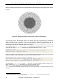
// UNLOCK THE DLL.
quadmesh::registration ("Licensed to SMART Inc.", "F53EA108BCWX");
// VERTICES AND LINE MESHES.
pos.push_back (P0);
pos.push_back (P1);
pos.push_back (P2);
pos.push_back (P3);
meshtools1d::mesh_straight (pos, 0, 1, N, indices); indices.pop_back();
meshtools1d::mesh_straight (pos, 1, 2, N, indices); indices.pop_back();
meshtools1d::mesh_straight (pos, 2, 3, N, indices); indices.pop_back();
meshtools1d::mesh_straight (pos, 3, 0, N, indices);
meshtools1d::indices_to_connectE2 (indices, connectB);
// THE 2D MESH.
quadmesh::mesher
the_mesher;
quadmesh::mesher::data_type
data (pos, connectB);
the_mesher.run (data);
data.print_info (&display_hdl);
// VISUALISATION.
meshtools::medit_output ("out.mesh", data.pos, data.connectM, CM2_FACEQ4);
return 0;
// main
}
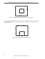
In this particular case, the generated mesh is a perfect structured quad mesh with all qualities equal to
113.
13
We could get the same structured Q4 mesh with meshtools2d::mesh_struct_Q4.
24
Copyright Computing Objects – October 2015
CM2 TriaMesh & QuadMesh – CM2 TriaMesh Aniso & QuadMesh Aniso - V 4.6
Figure 5 – Square meshed with quads.
For a plane quadrangle, we use the following measure of the shape quality:
Qs = 8 2
S min
Lmax P
with:
S min
Lmax
P
Minimum area of the four triangles.
Max length of the four sides and the two diagonals.
Perimeter of the quad.
This measure gives the maximal value 1 only for a square.
The size quality is given by the same measure as for the triangles (because it is based on edges only).
Copyright Computing Objects – October 2015
25
CM2 TriaMesh & QuadMesh – CM2 TriaMesh Aniso & QuadMesh Aniso - V 4.6
26
Copyright Computing Objects – October 2015
CM2 TriaMesh & QuadMesh – CM2 TriaMesh Aniso & QuadMesh Aniso - V 4.6
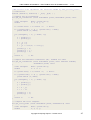
II-2 SQUARE WITH AN INTERNAL LINE
Starting from the previous example, we add a circle inside the square. Here is the program for a triangle
mesh:
#include "stdafx.h"
int main()
{
const double
const double
const unsigned
const unsigned
const DoubleVec2
const DoubleVec2
DoubleMat
UIntVec
UIntMat
L = 10.0;
R = 3.0;
N1 = 10;
N2 = 20;
P0(0.,0.), P1(L,0.), P2(L,L), P3(0.,L);
P4(L/2+R, L/2);
pos;
indices;
connectB;
// UNLOCK THE DLL.
triamesh::registration ("Licensed to SMART Inc.", "F53EA108BCWX");
// VERTICES AND LINE MESHES.
pos.push_back (P0);
pos.push_back (P1);
pos.push_back (P2);
pos.push_back (P3);
pos.push_back (P4);
meshtools1d::mesh_straight (pos, 0, 1, N, indices); indices.pop_back();
meshtools1d::mesh_straight (pos, 1, 2, N, indices); indices.pop_back();
meshtools1d::mesh_straight (pos, 2, 3, N, indices); indices.pop_back();
meshtools1d::mesh_straight (pos, 3, 0, N, indices);
meshtools1d::indices_to_connectE2 (indices, connectB);
indices.clear();
meshtools1d::extrude_rotate (pos, 4, DoubleVec2(L/2.,L/2.),
2.*M_PI, N2, indices);
indices.back() = indices.front();
meshtools1d::indices_to_connectE2 (indices, connectB);
// THE 2D MESH.
triamesh::mesher
triamesh::mesher::data_type
the_mesher.run (data);
the_mesher;
data (pos, connectB);
// VISUALISATION.
meshtools::medit_output ("out.mesh", data.pos, data.connectM, CM2_FACET3);
}
return 0;
// main
Copyright Computing Objects – October 2015
27
CM2 TriaMesh & QuadMesh – CM2 TriaMesh Aniso & QuadMesh Aniso - V 4.6
Figure 6 – Square with internal line (T3 and all-Q4).
The mesh of the circle is generated with the function extrude_rotate from the meshtools1d library.
The rotation is defined by a center, here by the point DoubleVec2(L/2,L/2), and a rotation scalar
around Oz, here 2*M_PI
The circular line is discretized using 20 elements14 starting from point #4. Here, the last generated point
- point #24 - is coincident with the first one - point #4. In order to topologically close the circle, it is
important to replace value 24 with value 4 in the indices vector, so that the first and the last point are
identical, not only coincident15:
indices.back() = indices.front();
As for the external contour, these indices are converted into edges with the indices_to_connectE2
function and appended to the connectB matrix. The meshing algorithm makes the difference between
external and internal boundary edges.
Again, to mesh with quads, we simply replace the triamesh namespace with quadmesh. Moreover, if
we accept some triangles, we can get a better mesh. This is the quad-dominant mode:
14 Remember that CM2 QuadMesh needs an even number of edges on each line (external and internal lines) in
all-quad mode.
15
Note that the coordinates at column 24 in the pos matrix will remain unused.
28
Copyright Computing Objects – October 2015
CM2 TriaMesh & QuadMesh – CM2 TriaMesh Aniso & QuadMesh Aniso - V 4.6
#include "stdafx.h"
int main()
{
const double
const double
const unsigned
const unsigned
DoubleMat
const DoubleVec2
const DoubleVec2
UIntVec
UIntMat
L = 10.0;
R = 3.0;
N1 = 10;
N2 = 20;
pos;
P0(0.,0.), P1(L,0.), P2(L,L), P3(0.,L);
P4(L/2+R, L/2);
indices;
connectB;
// UNLOCK THE DLL.
triamesh::registration ("Licensed to SMART Inc.", "F53EA108BCWX");
// VERTICES AND LINE MESHES.
pos.push_back (P0);
pos.push_back (P1);
pos.push_back (P2);
pos.push_back (P3);
pos.push_back (P4);
pos.push_back (DoubleVec2(L/2+R, L/2));
meshtools1d::mesh_straight (pos, 0, 1, N, indices); indices.pop_back();
meshtools1d::mesh_straight (pos, 1, 2, N, indices); indices.pop_back();
meshtools1d::mesh_straight (pos, 2, 3, N, indices); indices.pop_back();
meshtools1d::mesh_straight (pos, 3, 0, N, indices);
meshtools1d::indices_to_connectE2 (indices, connectB);
indices.clear();
meshtools1d::extrude_rotate (pos, 4, DoubleVec2(L/2.,L/2.),
2.*M_PI, N2, indices);
indices.back() = indices.front();
meshtools1d::indices_to_connectE2 (indices, connectB);
// THE 2D MESH.
quadmesh::mesher
the_mesher;
quadmesh::mesher::data_type
data (pos, connectB);
the_mesher.mode.all_quad_flag = false;
the_mesher.run (data);
// VISUALISATION.
meshtools:medit_output ("out.mesh", data.pos, data.connectM,
CM2_FACE_MIX);
}
return 0;
// main
Copyright Computing Objects – October 2015
29
CM2 TriaMesh & QuadMesh – CM2 TriaMesh Aniso & QuadMesh Aniso - V 4.6
Figure 7 – Square with internal line (quad-dominant mode).
30
Copyright Computing Objects – October 2015
CM2 TriaMesh & QuadMesh – CM2 TriaMesh Aniso & QuadMesh Aniso - V 4.6
II-3 SQUARE WITH INTERNAL HOLES
A hole is an internal closed contour with edges oriented the opposite way from the external contour.
Note that this implies that all edges of the external contour should be oriented in a uniform way (either
clockwise or counter-clockwise)16. Based on the previous example, we simply change the sign of the
rotation vector to revert the orientation of the internal edges and thus to remove the disk from the
domain:
meshtools1d::extrude_rotate (pos, 4, DoubleVec3(L/2.,L/2.),
-2.*M_PI, N2, indices);
And the resulting meshes give:
Figure 8 – Square with a circular hole (T3 and all-Q4).
One can nest alternatively positive and negative rotations:
16
Without any hole, the orientation of the external contour is irrelevant.
Copyright Computing Objects – October 2015
31
CM2 TriaMesh & QuadMesh – CM2 TriaMesh Aniso & QuadMesh Aniso - V 4.6
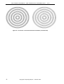
Figure 9 – Concentric circles with alternate orientation (T3 and all-Q4).
32
Copyright Computing Objects – October 2015
CM2 TriaMesh & QuadMesh – CM2 TriaMesh Aniso & QuadMesh Aniso - V 4.6
II-4 SQUARE WITH GRADING MESH SIZE
There are two ways to get a graded size in a mesh. First, you can simply generate edges with varying
size on the boundary or interior line. The mesher computes a size chart on each hard node17. It
interpolates these values inside the domain and generates elements accordingly.
To illustrate this, let us use again the example of the square. Instead of meshing regularly the four
segments of the contour, we will specify different target sizes on each four vertices:
#include "stdafx.h"
int main()
{
const double
const unsigned
const DoubleVec2
DoubleMat
UIntVec
DoubleVec
UIntMat
L = 10.0;
N = 10;
P0(0.,0.), P1(L,0.), P2(L,L), P3(0.,L);
pos;
indices, hard_nodes(5);
sizes(5);
connectB;
// UNLOCK THE DLL.
triamesh::registration ("Licensed to SMART Inc.", "F53EA108BCWX");
// VERTICES AND LINE MESHES.
pos.push_back (P0);
pos.push_back (P1);
pos.push_back (P2);
pos.push_back (P3);
hard_nodes[0] = 0; sizes[0] = 0.1*L/N;
hard_nodes[1] = 1; sizes[1] = 2.0*L/N;
hard_nodes[2] = 2; sizes[2] = 0.1*L/N;
hard_nodes[3] = 3; sizes[3] = 2.0*L/N;
hard_nodes[4] = 0; sizes[4] = 0.1*L/N;
meshtools1d::mesh_straight (pos, hard_nodes, sizes, true, indices);
meshtools1d::indices_to_connectE2 (indices, connectB);
// THE 2D MESH.
triamesh::mesher
triamesh::mesher::data_type
the_mesher.run (data);
the_mesher;
data (pos, connectB);
// VISUALISATION.
meshtools::medit_output ("out.mesh", data.pos, data.connectM, CM2_FACET3);
}
return 0;
// main
This variant of the mesh_straight function uses a vector of hard nodes, like a polygonal line, and a
vector of target size values, one value for each hard node. The contour mesh is generated to fit best the
target values on the four corners.
These target sizes are not used by the 2-D mesher. Only the resulting edge lengths of the contour will
be used to compute the 2-D size field.
17
By averaging the lengths of the adjacents edges to each hard node.
Copyright Computing Objects – October 2015
33
CM2 TriaMesh & QuadMesh – CM2 TriaMesh Aniso & QuadMesh Aniso - V 4.6
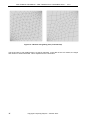
Figure 10 – Meshes with grading size (T3 and all-Q4).
The second way to get grading sizes is to specify manually, in the data of the 2-D mesher, the target
size values on some hard nodes. This is explained in the next section.
34
Copyright Computing Objects – October 2015
CM2 TriaMesh & QuadMesh – CM2 TriaMesh Aniso & QuadMesh Aniso - V 4.6
II-5 SQUARE WITH AN INTERNAL HARD NODE
Until now, we have seen only three fields of the structure used to exchange data with the mesher:
• The pos matrix for the coordinates of the points.
• The connectB matrix for the connectivity of the hard edges.
• The connectM matrix for the connectivity of the 2-D mesh.
In this example, we will add an isolated hard node at the center of the square and specify a target size
for the elements near this node. This will be done using the two new fields isolated_nodes and
metrics:
#include "stdafx.h"
int main()
{
const double
const unsigned
const DoubleVec2
DoubleMat
UIntVec
UIntMat
L = 10.0;
N = 10;
P0(0.,0.), P1(L,0.), P2(L,L), P3(0.,L), P4(L/2.,L/2.);
pos;
indices;
connectB;
// UNLOCK THE DLL.
triamesh::registration ("Licensed to SMART Inc.", "F53EA108BCWX");
// VERTICES AND LINE MESHES.
pos.push_back (P0);
pos.push_back (P1);
pos.push_back (P2);
pos.push_back (P3);
pos.push_back (P4);
meshtools1d::mesh_straight (pos, 0, 1, N, indices); indices.pop_back();
meshtools1d::mesh_straight (pos, 1, 2, N, indices); indices.pop_back();
meshtools1d::mesh_straight (pos, 2, 3, N, indices); indices.pop_back();
meshtools1d::mesh_straight (pos, 3, 0, N, indices);
meshtools1d::indices_to_connectE2 (indices, connectB);
// THE 2D MESH.
triamesh::mesher
the_mesher;
triamesh::mesher::data_type
data (pos, connectB);
data.isolated_nodes.push_back (4);
data.metrics.resize (5, 0.0);
data. metrics[4] = 0.1*L/N;
the_mesher.run (data);
// VISUALISATION.
meshtools::medit_output ("out.mesh", data.pos, data.connectM, CM2_FACET3);
}
return 0;
// main
We have created a new point at the center with coordinates placed in column #4 of matrix pos. Its
index, i.e. 4, is then pushed into the vector data.isolated_nodes. This new field serves to store all
the isolated nodes that must be present in the final mesh.
Copyright Computing Objects – October 2015
35
CM2 TriaMesh & QuadMesh – CM2 TriaMesh Aniso & QuadMesh Aniso - V 4.6
The vector data.metrics stores the user-specified target sizes. If the value for a node is zero - or
negative or not present -, the automatically computed value will be used instead18.
In our example, the vector is resized to 5 with all values set to zero except for point #4 where we ask for
a 10 times finer mesh around it.
Figure 11 – Mesh concentration near a hard node (T3 and all-Q4).
18
For an isolated node, the computed size is based on the size value of the nearest nodes.
36
Copyright Computing Objects – October 2015
CM2 TriaMesh & QuadMesh – CM2 TriaMesh Aniso & QuadMesh Aniso - V 4.6
II-6 MULTIPLE MESHES
The matrix connectB can contain several internal lines. It can also contain several external contours.
This means that several disconnected domains can be meshed simultaneously. Some care must be
taken however in the orientation of these contours. For multiple domains, the edges of all external
contours must be oriented the same way, for instance counter-clockwise (the so-called positive
orientation). In addition, these contours must not intersect each other.
Figure 12 – Multiple meshes (T3 and all-Q4).
The four domains are meshed simultaneously.
In this example, the coordinates matrix and the connectivity of the contour meshes are read from a
file19:
19
We could also have used the function meshtools1d::mesh_spline which generate 1D meshes along
splines.
Copyright Computing Objects – October 2015
37
CM2 TriaMesh & QuadMesh – CM2 TriaMesh Aniso & QuadMesh Aniso - V 4.6
#include "stdafx.h"
int main()
{
ifstream
triamesh::mesher
triamesh::mesher::data_type
istrm ("cards.dat");
the_mesher;
data;
triamesh::registration ("Licensed to SMART Inc.", "F53EA108BCWX");
matio::read (istrm, data.pos);
matio::read (istrm, data.connectB);
the_mesher.run (data);
meshtools::medit_output ("out.mesh", data.pos, data.connectM, CM2_FACET3);
}
return 0;
// main
The input boundary meshes are read from an ASCII file with matio::read20.
The format for the matrices is:
n X m
d0,0
d1,0
...
dn-1,0
[
d0,1
d1,1
d0,2
d1,2
dn-1,1
... d0,m-1
... d1,m-1
dn-1,2... dn-1,m-1 ]
The format for each component of the matrix is free.
For instance a 2x4 DoubleMat can be stored as:
2 X 4 [
0 0.5 1
0 1 1
2.0
2.E-1]
Notes:
• We can see also in this example that the meshes may not be symmetric with a symmetric
contour.
• In the all-quad case, we set indeed the flag multi_structured_flag = true. This is the
reason why the diamond is meshed in a structured manner.
As an exercise, we can get the same result by making four successive meshes and concatenating the
results:
20
A similar matio::transpose_read function can read a matrix and transpose it on the fly.
This can be more useful because it is usually more convenient to store the transposed matrices in the ASCII files.
38
Copyright Computing Objects – October 2015
CM2 TriaMesh & QuadMesh – CM2 TriaMesh Aniso & QuadMesh Aniso - V 4.6
#include "stdafx.h"
int main()
{
ifstream
UIntMat
DoubleMat
istrm
connectM;
pos;
triamesh::registration ("Licensed to SMART Inc.", "F53EA108BCWX");
triamesh::mesher
triamesh::mesher::data_type
the_mesher;
data;
istrm.open ("heart.dat");
matio::read (istrm, data.pos);
matio::read (istrm, data.connectB);
the_mesher.run (data);
pos.push_back (data.pos);
connectM.push_back (data.connectM);
istrm.open ("spade.dat");
matio::read (istrm, data.pos);
matio::read (istrm, data.connectB);
the_mesher.run (data);
matscal::add (pos.cols(), data.connectM);
pos.push_back (data.pos);
connectM.push_back (data.connectM);
istrm.open ("diamond.dat");
matio::read (istrm, data.pos);
matio::read (istrm, data.connectB);
the_mesher.run (data);
matscal::add (pos.cols(), data.connectM);
pos.push_back (data.pos);
connectM.push_back (data.connectM);
istrm.open ("club.dat");
matio::read (istrm, data.pos);
matio::read (istrm, data.connectB);
the_mesher.run (data);
matscal::add (pos.cols(), data.connectM);
pos.push_back (data.pos);
connectM.push_back (data.connectM);
// Shift indices.
// Shift indices.
// Shift indices.
meshtools::medit_output ("out.mesh", pos, connectM, CM2_FACET3);
}
return 0;
// main
Copyright Computing Objects – October 2015
39
CM2 TriaMesh & QuadMesh – CM2 TriaMesh Aniso & QuadMesh Aniso - V 4.6
40
Copyright Computing Objects – October 2015
CM2 TriaMesh & QuadMesh – CM2 TriaMesh Aniso & QuadMesh Aniso - V 4.6
II-7 SHARED BOUNDARIES
Edges can be shared between some contours and lines. In this case, some edges are defined several
times (usually twice) in the connectB matrix, but with different orientation. In addition, it is sometimes
more convenient for the user to generate the 1D meshes of the contours independently from each
other. That usually implies duplicated nodes on the shared contours.
The following example deals with such a case.
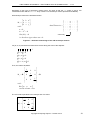
Consider three subdomains, all oriented counter-clockwise as defined below. Several edges are shared
between subdomains, but with different orientation. We also want to mesh the contours of the
subdomains independently from each other but without any duplicated nodes.
P6
P7
P5
P8
P9
P4
P3
P0
P2
P1
Figure 13 – Domain composed of three attached subdomains.
The shared edges are no problem for the mesher. The duplicate nodes however must be avoided. In
non-strict mode (see § III-3), duplicated nodes can be discarded indeed but that implies also that the
associated edges cannot be enforced. As a side effect, the mesher may not be able to tell the sign of
the inner square, and that can lead to a hole.
The solution consists in merging the nodes after the meshing of the edges before the 2-D meshing:
Copyright Computing Objects – October 2015
41
CM2 TriaMesh & QuadMesh – CM2 TriaMesh Aniso & QuadMesh Aniso - V 4.6
#include "stdafx.h"
static void mesh_segment
(DoubleMat& pos, UIntMat& connectB,
unsigned start_index, unsigned stop_index, unsigned num_edges)
{
UIntVec
indices;
meshtools1d::mesh_straight
(pos, start_index, stop_index, num_edges, indices);
meshtools1d::indices_to_connectE2 (indices, connectB);
}
int main()
{
const DoubleVec2
const DoubleVec2
const DoubleVec2
const DoubleVec2
const DoubleVec2
const DoubleVec2
const DoubleVec2
const DoubleVec2
const DoubleVec2
const DoubleVec2
const unsigned
UIntMat
P0(0, 0);
P1(10, 0);
P2(10, 2);
P3(8, 2);
P4(2, 2);
P5(0, 2);
P6(10, 10);
P7(0, 10);
P8(2, 8);
P9(8, 8);
N = 4;
connectB;
// UNLOCK THE DLL.
triamesh::registration ("Licensed to SMART Inc.", "F53EA108BCWX");
// VERTICES POINTS.
pos.push_back (P0);
pos.push_back (P1);
pos.push_back (P2);
pos.push_back (P3);
pos.push_back (P4);
pos.push_back (P5);
pos.push_back (P6);
pos.push_back (P7);
pos.push_back (P8);
// BOTTOM RECTANGLE POSITIVE
mesh_segment (pos, connectB,
mesh_segment (pos, connectB,
mesh_segment (pos, connectB,
mesh_segment (pos, connectB,
mesh_segment (pos, connectB,
mesh_segment (pos, connectB,
(I.E.
0, 1,
1, 2,
2, 3,
3, 4,
4, 5,
5, 0,
// TOP HORSESHOE POSITIVE (I.E.
mesh_segment (pos, connectB, 2,
mesh_segment (pos, connectB, 6,
mesh_segment (pos, connectB, 7,
mesh_segment (pos, connectB, 5,
mesh_segment (pos, connectB, 4,
mesh_segment (pos, connectB, 8,
mesh_segment (pos, connectB, 9,
mesh_segment (pos, connectB, 3,
COUNTER-CLOCKWISE).
N);
N);
N);
N);
N);
N);
COUNTER-CLOCKWISE).
6, N);
7, N);
5, N);
4, N);
8, N);
9, N);
3, N);
2, N);
// INNER SQUARE POSITIVE (I.E. COUNTER-CLOCKWISE).
mesh_segment (pos, connectB, 3, 9, N);
mesh_segment (pos, connectB, 9, 8, N);
42
Copyright Computing Objects – October 2015
CM2 TriaMesh & QuadMesh – CM2 TriaMesh Aniso & QuadMesh Aniso - V 4.6
mesh_segment (pos, connectB, 8, 4, N);
mesh_segment (pos, connectB, 4, 3, N);
// MERGE TOGETHER DUPLICATED NODES.
meshtools::merge (pos, connectB);
// THE 2D MESH.
triamesh::mesher
triamesh::mesher::data_type
the_mesher.run (data);
the_mesher;
data (pos, connectB);
// VISUALISATION.
meshtools::medit_output ("out.mesh", data.pos, data.connectM, CM2_FACET3);
}
return 0;
// main
Note that this solution works because the shared edges are discretized similarly and the nodes are
coincident.
Figure 14 – Example with shared boundaries (T3 and all-Q4).
Note that the contour of the inner square is oriented completely both ways (positive and negative). In
such a case, the mesher favors the positive orientation and meshes the inner square.
A similar case occurs when an inner contour is not properly oriented (see figure below). The mesher
considers the inner domain to have the same status as the "most external domain” adjacent to it. Here
the most external domain adjacent to the inner square is the outer square. Hence, the inner square will
be meshed (i.e. no hole).
Copyright Computing Objects – October 2015
43
CM2 TriaMesh & QuadMesh – CM2 TriaMesh Aniso & QuadMesh Aniso - V 4.6
Figure 15 – Example of ambiguous orientation of an inner contour.
Here is another example where a hole is adjacent to the external contour. In this case, the most
external domain adjacent to the inner square is the outside void. Hence, the inner square will not be
meshed (i.e. hole).
Figure 16 – Hole adjacent to the external contour.
44
Copyright Computing Objects – October 2015
CM2 TriaMesh & QuadMesh – CM2 TriaMesh Aniso & QuadMesh Aniso - V 4.6
Figure 17 – Hole adjacent to the external contour (T3 and Q4).
Copyright Computing Objects – October 2015
45
CM2 TriaMesh & QuadMesh – CM2 TriaMesh Aniso & QuadMesh Aniso - V 4.6
46
Copyright Computing Objects – October 2015
CM2 TriaMesh & QuadMesh – CM2 TriaMesh Aniso & QuadMesh Aniso - V 4.6
II-8 BACKGROUND MESH
Sometimes it is not convenient to specify the target mesh sizes at the hard nodes. Non-regular
variations of the sizes inside the domain can be needed but the use of many hard nodes scattered over
the domain should be avoided. This is the case especially when automatic mesh adpativity is involved.
The "background mesh" option is the solution in this case.
The background mesh is an auxiliary mesh used by the mesher to find the target mesh size at any point
inside the domain. Hence, the user controls exactly the size chart on the entire domain.
This background mesh is represented by the connectivity matrix background_mesh in the data of the
mesher. As always, the indices of the nodes refer to columns in the same pos matrix as all other
connectivity matrices or vectors (such as connectM). The nodes of the background mesh must all have
a valid associated size value in the metrics array.
In the following example, a regular structured background mesh is used to support a size field with a
sinusoidal variation in the two directions. The domain to be meshed is a simple square regularly
discretized along its boundaries21.
21
For a change, we use here the mesh_straight overload with the parameters for the sizes at the extremities.
Copyright Computing Objects – October 2015
47
CM2 TriaMesh & QuadMesh – CM2 TriaMesh Aniso & QuadMesh Aniso - V 4.6
#include "stdafx.h"
int main()
{
const double
const double
const double
DoubleMat
UIntVec
UIntMat
DoubleVec
unsigned
double
L = 4.0;
h0 = 0.25;
h1 = 0.05;
pos;
indices;
connectE2, connectT3, BGM;
sizes;
N_BGM, n;
w, h;
// UNLOCK THE DLL.
triamesh::registration ("Licensed to SMART Inc.", "F53EA108BCWX");
// VERTICES AND LINE MESHES.
pos.push_back (DoubleVec2(-L/2,-L/2));
pos.push_back (DoubleVec2 (+L/2,-L/2));
pos.push_back (DoubleVec2 (+L/2,+L/2));
pos.push_back (DoubleVec2 (-L/2,+L/2));
meshtools1d::mesh_straight (pos, 0, 1, h0, h0, true, indices);
indices.pop_back();
meshtools1d::mesh_straight (pos, 1, 2, h0, h0, true, indices);
indices.pop_back();
meshtools1d::mesh_straight (pos, 2, 3, h0, h0, true, indices);
indices.pop_back();
meshtools1d::mesh_straight (pos, 3, 0, h0, h0, true, indices);
meshtools1d::indices_to_connectE2 (indices, connectE2);
// THE BACKGROUND MESH.
N_BGM = unsigned(L/h1);
// The discretization for the background mesh.
indices.clear();
meshtools1d::mesh_straight (pos, 0, 1, N_BGM, indices);
indices.pop_back();
meshtools1d::mesh_straight (pos, 1, 2, N_BGM, indices);
indices.pop_back();
meshtools1d::mesh_straight (pos, 2, 3, N_BGM, indices);
indices.pop_back();
meshtools1d::mesh_straight (pos, 3, 0, N_BGM, indices);
meshtools2d::mesh_struct_T3 (pos, indices, N_BGM, true, BGM);
// THE METRICS ON THE BACKGROUND MESH.
indices.clear();
meshtools::unique_indices (indices, BGM);
sizes.resize (pos.cols(), 0.0);
// Null value for nodes not in BGM.
for (unsigned i = 0; i < indices.size(); ++i)
{
n = indices[i];
w = std::max(::fabs(pos(0,n)), ::fabs(pos(1,n)));
h = ::cos(8.*M_PI*w/L) * (h0-h1)/2. + (h0+h1)/2.;
sizes[n] = h;
}
// THE 2D MESH.
triamesh::mesher
triamesh::mesher::data_type
data.background_mesh = BGM;
data.metrics = sizes;
the_mesher.run (data);
48
the_mesher;
data (pos, connectE2);
Copyright Computing Objects – October 2015
CM2 TriaMesh & QuadMesh – CM2 TriaMesh Aniso & QuadMesh Aniso - V 4.6
// VISUALISATION.
meshtools::medit_output ("out.mesh", data.pos, data.connectM, CM2_FACET3);
}
return 0;
// main
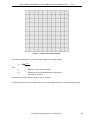
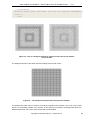
Figure 18 – Use of a background mesh to support a sizes field on the domain
(T3 and all-Q4).
The background mesh is the same structured triangle mesh in both cases:
Figure 19 – The background mesh used in the previous example.
The background mesh does not need to fit exactly the domain to be meshed. It can cover only a small
part of it or be partially outside of the domain. In the areas not covered by the background mesh, the
default interpolation of the sizes at the hard nodes is used instead.
Copyright Computing Objects – October 2015
49
CM2 TriaMesh & QuadMesh – CM2 TriaMesh Aniso & QuadMesh Aniso - V 4.6
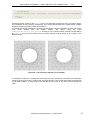
Here is an example where the domain is a disk and the background mesh is also a disk but with half the
radius. We have set a uniform value for the sizes field on the background mesh to get a finer mesh in
this area.
Figure 20 – Background mesh covering only a fraction of the domain.
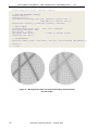
The next step is when the boundary mesh of the domain must also be governed by a background
mesh. In addition to the 2D-background mesh, we need also to discretize the boundary in order to
support the sizes field on this line. Then, the real boundary mesh is generated using this 1D
"background mesh" and the associated sizes. The discretization for this 1D "background mesh" must be
fine enough to represent accurately the geometry of the line.
An overload of the meshtools1d::mesh_line function does this job22. Here, we discretize a full
circle with 200 nodes in indices0 and keep the associated parameters in the U0 vector:
n_bgm = R / 100.;
meshtools1d::extrude_rotate (pos, 1, CR, 2*M_PI, n_bgm, indices0);
indices0.back() = indices0.front();
Sizes are specified on the nodes of this arc and on the 2D-background mesh as well. Then, the circle is
remeshed using the initial discretization of the circle and the new sizes field:
vecvec::push_back (sizes, indices0, sizes0);
cm2::meshtools1d::mesh_line (pos, indices0, sizes0, true, 1,
UINT_MAX, 0.0, indices, new_U);
meshtools1d::indices_to_connectE2 (indices, connectE);
The parameters true, 1, UINT_MAX and 0.0 stand for: force even number of edges, minimum of 1
edge, maximum of UINT_MAX edges along the arc and no chordal control23.
The indices vector contains now the nodes of the real boundary mesh.
new_U contains their parameter values along the circle, but this vector is not used in the rest of the
example.
22
23
Several overloads for mesh_straight, mesh_spline and mesh_line exist in the meshtools1d library.
See online doc for more info on these parameters.
50
Copyright Computing Objects – October 2015
CM2 TriaMesh & QuadMesh – CM2 TriaMesh Aniso & QuadMesh Aniso - V 4.6
#include "stdafx.h"
int main()
{
const double
const double
const double
const double
const DoubleVec2
const DoubleVec2
DoubleMat
DoubleVec
UIntVec
UIntMat
unsigned
double
DoubleVec
R
= 4.0;
h0 = 0.5;
h1 = 0.1;
sig = 0.2;
CR (0,0);
P0 (R,0);
pos;
sizes, sizes0;
indices0, indices;
connectE, connectM, BGM;
n_bgm, n;
x, y, w, w0, w1, w2, h;
U0, new_U;
// UNLOCK THE DLL.
triamesh::registration ("Licensed to SMART Inc.", "F53EA108BCWX");
triamesh::mesher
the_mesher;
pos.push_back (CR);
pos.push_back (P0);
// THE 2D BACKGROUND MESH
n_bgm = unsigned(2.*M_PI*R / h1);
// The discretization for the BGM.
meshtools1d::extrude_rotate (pos, 1, CR, 2*M_PI, n_bgm, indices);
indices.back() = indices.front();
// CLose the circle.
meshtools1d::indices_to_connectE2 (indices, connectE);
triamesh::mesher::data_type
BGMdata (pos, connectE);
the_mesher.mode.optim_level = 0;
// No need to have a very good BGM.
the_mesher.run (BGMdata);
BGMdata.extract (pos, BGM);
// MESH THE GEOMETRIC SUPPORT OF THE BOUNDARY (1D BACKGROUND MESH).
n_bgm = R / 100.;
meshtools1d::extrude_rotate (pos, 1, CR, 2*M_PI, n_bgm, indices0);
indices0.back() = indices0.front();
// THE METRICS ON THE BACKGROUND MESHES.
indices.clear();
meshtools::unique_indices (indices, BGM);
std::copy (indices0.begin(), indices0.end(), back_inserter(indices));
sizes.resize (pos.cols(), 0.0);
for (unsigned i = 0; i < indices.size(); ++i)
{
n = indices[i];
x = pos(0,n);
y = pos(1,n);
w0 = ::fabs(y + 2.*x - R/2);
w1 = ::fabs(y - x- R/2);
w2 = ::fabs(x + R/2);
w = std::min(w0, w1);
w = std::min(w, w2) / sig;
h = 1. / ((1./h0) + (1./h1) * ::exp(-w*w));
sizes[n] = h;
}
// Pickup the sizes along the circle.
sizes0.clear();
Copyright Computing Objects – October 2015
51
CM2 TriaMesh & QuadMesh – CM2 TriaMesh Aniso & QuadMesh Aniso - V 4.6
vecvec::push_back (sizes, indices0, sizes0);
// MESH THE EXTERNAL CONTOUR.
indices.clear();
connectE.clear();
cm2::meshtools1d::mesh_line (pos, indices0, sizes0, true, 1,
UINT_MAX, 0.0, indices, new_U);
meshtools1d::indices_to_connectE2 (indices, connectE);
// THE 2D MESH.
triamesh::mesher::data_type
data.background_mesh = BGM;
data.metrics = sizes;
the_mesher.mode.reset();
the_mesher.run (data);
data (pos, connectE);
// Reset to default values.
// VISUALISATION.
meshtools::medit_output ("out.mesh", data.pos, data.connectM, CM2_FACET3);
}
return 0;
// main
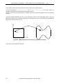
Figure 21 – Background meshes for both the boundary and the domain
(T3 and all-Q4).
52
Copyright Computing Objects – October 2015
CM2 TriaMesh & QuadMesh – CM2 TriaMesh Aniso & QuadMesh Aniso - V 4.6
II-9 ANISOTROPIC MESHES
CM2 TriaMesh and CM2 QuadMesh are isotropic unstructured meshers, that is, they tend to produce
equilateral triangles and squares. It is sometimes useful however to have elements "stretched" in some
special directions. To deal with complex domains, we still need an unstructured mesher. Here come the
anisotropic unstructured meshers CM2 TriaMesh Aniso and CM2 QuadMesh Aniso. They are almost
identical to their isotropic counterparts except for the data.metrics array that is now a matrix. In the
isotropic case, we need only a scalar at each node to define the target mesh size. Now, the target mesh
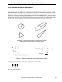
size is defined by a 2x2 symmetric matrix at each node, stored column-wise in the metrics array.
h1
h
h0
P
P
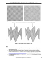
Figure 22 – A single scalar defines an isotropic metric (left).
A 2D-anisotropic metric needs two vectors (right).
M j = a b
b c
with :
a>0
a c − b2 > 0
i.e. the two eigen values are > 0
. . . a . . .
data.metrics = . . . b . . .
. . . c . . .
column #j
Figure 23 – Definition and storage of the 2-D anisotropic metrics.
Let (v0, v1) be the two orthonormal vectors along the axes of the ellipse:
v 0 = v1 = 1
v 0 , v1 = 0
Then, the metrics Mj writes:
Copyright Computing Objects – October 2015
53
CM2 TriaMesh & QuadMesh – CM2 TriaMesh Aniso & QuadMesh Aniso - V 4.6
1
h 2
Mj =B 0
0
with :
B = [v 0
0
1
2
h1
T
B
v1 ]
stored column − wise
The metric equivalent to an isotropic size of h writes:
1
2
M j = h
0
0
1
h2
A null matrix would lead to infinite sizes in both directions (infinite circle).
When the user doesn’t specify a metric, the mesher uses the default one which is equivalent to the
isotropic default metrics we have seen before. For each hard node, the default metric is based on the
length of the adjacent edges. This leads to the same default behavior as their related isotropic
counterparts. Take for instance examples II-1, II-2, II-3 or II-4 and replace:
triamesh::mesher
the_mesher;
with:
triamesh_aniso::mesher the_mesher;
and you get the same meshes24.
To benefit from the anisotropic features, the user must fill the metrics array with valid anisotropic
matrices (i.e. positive-definite matrices). Some functions in meshtools and meshtools1d can help in
computing these matrices, as in the following example.
24
The anisotropic meshers are however significantly slower than their isotropic counterparts.
54
Copyright Computing Objects – October 2015
CM2 TriaMesh & QuadMesh – CM2 TriaMesh Aniso & QuadMesh Aniso - V 4.6
Figure 24 – Anisotropic meshes (T3 and Q4).
Here a square is meshed non-uniformly with the variant of mesh_straight we have already seen in
the previous section25. This is not sufficient to get a 2-D anisotropic mesh. We need an anisotropic
mesher. We need also to specify that we want a different size along the normals than along the
tangents of the boundary lines (along the tangents the default sizes, i.e. mean of the edges’ lengths,
suit us). This is the role of meshtools1d::metrics_gen_aniso2d. This function takes a 1D mesh
and a size along the normal and generates a set of 2-D anisotropic metrics stored in array metrics as
depicted in Figure 23. At each node Ni, a metric M(Ni, hn) is computed. For instance, along the right
vertical line we specify a constant size hx in the horizontal direction26:
meshtools1d::metrics_gen_aniso2d (pos, connect2, /*hn=>*/ hx, metrics);
25
We could obviously get about the same structured Q4 mesh with meshtools2d::mesh_struct_Q4.
Note that the metrics parameter is not a pure out parameter. Indeed, this function does not simply overwrite
the existing columns in metrics but replace them with their intersection with the newly computed metric M(Ni, hn).
If Mi in column #i already exists in metrics, Mi is replaced by intersection (Mi, M(Ni, hn)). Using the ellipse
representation of the metrics, intersection (Mi, Mj) is the ellipse inscribed inside the two associated ellipses.
Note also that a null metric is equivalent to an infinite circle, and that intersection (Mi, 0) = Mi
This property of the metrics_gen_aniso2d function is essential to make coherant the intersections of the
generated metrics at the four sommits of the square.
26
Copyright Computing Objects – October 2015
55
CM2 TriaMesh & QuadMesh – CM2 TriaMesh Aniso & QuadMesh Aniso - V 4.6
#include "stdafx.h"
int main()
{
const double
const double
const double
const double
const DoubleVec2
const DoubleVec2
const DoubleVec2
const DoubleVec2
DoubleMat
UIntVec
UIntMat
UIntMat
DoubleMat
L
= 10.0;
hx = 1.0;
h0y = hx;
// Y size at bottom line.
h1y = hx / 20.;
// Y size at top line.
P0(0,0);
P1(L,0);
P2(L,L);
P3(0,L);
pos;
indices;
connect1, connect2, connect3, connect4, connectE;
connectM;
metrics;
// UNLOCK THE DLL.
triamesh::registration ("Licensed to SMART Inc.", "F53EA108BCWX");
// VERTICES
pos.push_back
pos.push_back
pos.push_back
pos.push_back
(P0);
(P1);
(P2);
(P3);
// BOTTOM LINE
indices.clear();
meshtools1d::mesh_straight (pos, 0, 1, hx, hx, true, indices);
meshtools1d::indices_to_connectE2 (indices, connect1);
connectE.push_back (connect1);
// RIGHT-SIDE LINE
indices.clear();
meshtools1d::mesh_straight (pos, 1, 2, h0y, h1y, true, indices);
meshtools1d::indices_to_connectE2 (indices, connect2);
connectE.push_back (connect2);
// LEFT-SIDE LINE
indices.clear();
meshtools1d::mesh_straight (pos, 2, 3, hx, hx, true, indices);
meshtools1d::indices_to_connectE2 (indices, connect3);
connectE.push_back (connect3);
// TOP LINE
indices.clear();
meshtools1d::mesh_straight (pos, 3, 0, h1y, h0y, true, indices);
meshtools1d::indices_to_connectE2 (indices, connect4);
connectE.push_back (connect4);
// METRICS
meshtools1d::metrics_gen_aniso2d
meshtools1d::metrics_gen_aniso2d
meshtools1d::metrics_gen_aniso2d
meshtools1d::metrics_gen_aniso2d
// 2D MESH
triamesh_aniso::mesher
triamesh_aniso::mesher::data_type
data.metrics = metrics;
the_mesher.run (data);
56
(pos,
(pos,
(pos,
(pos,
connect1,
connect2,
connect3,
connect4,
/*hn=>*/ h0y, metrics);
/*hn=>*/ hx, metrics);
/*hn=>*/ h1y, metrics);
/*hn=>*/ hx, metrics);
the_mesher;
data (pos, connectE2);
Copyright Computing Objects – October 2015
CM2 TriaMesh & QuadMesh – CM2 TriaMesh Aniso & QuadMesh Aniso - V 4.6
// VISUALISATION.
meshtools::medit_output ("out.mesh", data.pos, data.connectM, CM2_FACET3);
}
return 0;
// main
As already stated, except for the metrics array, the anisotropic meshers have the very same options
and parameters as their isotropic counterparts. They accept internal hard lines, isolated nodes, multiple
domains, shared boundaries, background meshes...
The following example illustrates the internal hard line feature. We have specified a normal size on the
circle
much
smaller
than
the
default
tangent
size
(again
using
the
same
meshtools1d::metrics_gen_aniso2d function). For the external square, nothing was specified in
the metrics array and the mesher used its default isotropic metrics based on the length of the
adjacent edges
Figure 25 – 2-D anisotropic meshes (T3 and all-Q4).
The example in Figure 21 is revisited the anisotropic way. Here, we specify a small size in the directions
normal to the three lines but a uniform size along the tangents. The normal sizes follow the same kind
of Gaussian variation. All these metrics are specified at the nodes of the same uniform background
mesh.
Copyright Computing Objects – October 2015
57
CM2 TriaMesh & QuadMesh – CM2 TriaMesh Aniso & QuadMesh Aniso - V 4.6
Figure 26 – 2-D anisotropic meshes (T3 and all-Q4).
58
Copyright Computing Objects – October 2015
CM2 TriaMesh & QuadMesh – CM2 TriaMesh Aniso & QuadMesh Aniso - V 4.6
II-10 3-D SURFACE MESHES (ANISO MESHERS
ONLY)
The four meshers TriaMesh, QuadMesh and their anisotropic versions TriaMesh Aniso and
QuadMesh Aniso are plane 2-D meshers. They generate or optimize meshes in the Z = 0 plane only.
To generate meshes on 3-D parametric surfaces, CM2 MeshTools offers convenient solutions by the
way of a template function that pre- and post-process the data for a 2-D anisotropic mesher
(TriaMesh Aniso or QuadMesh Aniso):
template <class Surface, class AnisoMesher, class AuxMesher>
int
meshtools2d::mesh_surface_param
(const Surface& S, AnisoMesher& mesher2D,
typename AnisoMesher::data_type& data3D, AuxMesher& aux_mesher,
double max_chordal_error, double min_h, unsigned chordal_control_type,
unsigned high_order_type = 0, unsigned max_bgm_remeshings = 4,
bool recompute_Qs_flag = true, bool compute_area_flag = true,
double progress_start = 0.0, double progress_range = 1.0);
This function can be used as in the following code sample:
triamesh_aniso::mesher
the_mesher;
triamesh::mesher
aux_mesher;
triamesh_aniso::mesher::data_type
data (pos, connectE2);
surface_type
S(...);
// A parametric surface.
meshtools2d::mesh_surface_param (S, the_mesher, data,
aux_mesher, -0.05, 0.0, 4);
data.extract (pos, connectM);
The class Surface for parameter S is a concept of parametric surface with members:
int get_3D_coordinates (const DoubleMat& pos2D, DoubleMat& pos3D) const;
int get_2D_coordinates (const DoubleMat& pos3D, const UIntVec& nodeIDs,
DoubleMat& pos2D) const;
int get_local_bases (const DoubleMat& pos2D, DoubleMat& local_B) const;
int get_local_curvatures (const DoubleMat& pos2D, DoubleMat& local_H) const;
The Surface::get_3D_coordinates member should compute the 3-D coordinates of a set of 2-D
points located on the reference plane. The 3-D coordinates of the point in column #j of pos2D must be
returned in column #j of pos3D.
This function should return zero when successful.
The Surface::get_2D_coordinates member is the reciprocal function of the previous one27. It
should give the coordinates in the 2-D reference plane of a set of 3-D points. The reference coordinates
of the point in column #j of pos3D must be returned in column #j of pos2D.
This function should return zero when successful
nodeIDs is an auxiliary vector that can be helpful for an effective implementation. It contains the global
indices of the nodes for which the 2-D coordinates are required. These are the indices in the the global
matrix data3D.pos: nodeIDs[j] is the node ID (i.e. column in data.pos) for the coordinates in
27
For parametric surfaces such as Bezier surfaces or NURB surfaces, the computation of reference coordinates
often involves a non-linear search. However, this function is called only for the nodes on the boundary mesh and
for the isolated nodes (i.e. the hard nodes only). It is not called for the new nodes generated inside the surface by
the mesher.
Copyright Computing Objects – October 2015
59
CM2 TriaMesh & QuadMesh – CM2 TriaMesh Aniso & QuadMesh Aniso - V 4.6
column j of pos3D. This array can be used for fast 2-D coordinates retrieval if these coordinates have
been computed before.
The Surface::get_local_bases member should compute the two tangents Bu =
Bv =
∂P
on the surface at a set of points given by their reference coordinates.
∂v
∂P
and
∂u
These tangents must not be normalized. They are the mere derivatives of the surface with respect to
two reference parameters. The two tangents at the point in column #j of pos2D must be returned in
column #j of local_B (dimension 6xN). The first three values are for the first tangent (with respect to
the first reference coordinate), then the next three are for the second tangent28.
This function should return zero when successful.
The Surface::get_local_curvatures function may compute the curvatures of the surface at a
set of points given by their reference coordinates (optional).
The curvatures H are 2x2 symmetric matrices defined as:
•
H uu =
∂2P
,N
∂u 2
Dot product between the derivative of
•
Bu (first local tangent) with respect to u, and the normal
N to the surface.
∂2P
H uv =
,N
∂u ∂v
Dot product between the derivative of
Bu (first local tangent) with respect to v, or derivative of
Bv (second local tangent) with respect to u, and the normal N to the surface.
•
H vv =
∂2P
,N
∂v 2
Dot product between the derivative of
Bv (second local tangent) with respect to v, and the
normal N to the surface.
These three values must be stored column-wise in matrix local_H:
H uu on row 0, H uv on row 1 and
H vv on row 2.
This function should return zero when successful and a negative value (-1 for instance) when failed.
You can leave the implementation of this member empty (returning -1 for instance). In this case
approximative curvatures computed from variations of the tangents will be used instead.
The template class AnisoMesher is a concept of triangle anisometric mesher with function:
void run (typename AnisoMesher::data_type& data) const;
The mesh_surface_param function is designed to work with one of the 2-D anisotropic meshers
CM2 TriaMesh Aniso or CM2 QuadMesh Aniso.
The data3D parameter is the structure gathering all the input and output data, just like for any other
unstructured
mesher
of
CM2
MeshTools.
The
type
of
data3D
is
either
triamesh_aniso::mesher::data_type
or
quadmesh_aniso::mesher::data_type
28
This function should normally return in local_B only valid bases made of two non-null and non-colinear
vectors. When the surface exhibits some singularities, the user can "correct" the deficient bases. As far as the
mesher is concerned, the exactness of these tangents with respect to the true surface is not critical. More precisely,
the tangent bases are used by the template function as transformation matrices to compute the target anisotropic
2-D metrics array. The template function checks for deficient aniso metrics (derived from deficient local bases)
and replace them with a default one.
60
Copyright Computing Objects – October 2015
CM2 TriaMesh & QuadMesh – CM2 TriaMesh Aniso & QuadMesh Aniso - V 4.6
depending on the type of anisotropic mesher used. The point is that the pos matrix is now a 3-D
coordinates matrix and the metrics array contains 3-D anisotropic metrics (dimensions 6xNODS).
3D-anisotropic metrics are defined as below:
a b d
M j = b c e
d e f
with :
.
.
data3D.metrics = .
.
.
.
a>0
a c − b2 > 0
Det ( M j ) > 0
.
.
.
.
.
.
. a . . .
. b . . .
. c . . .
. d . . .
. e . . .
. f . . .
column #j
i.e. the three eigen values are > 0
Figure 27 – Definition and storage of the 3-D anisotropic metrics.
Let (v0, v1, v2) be the three orthonormal vectors along the axes of the ellipsoid:
v0 = v1 = v 2 = 1
v 0 , v1 = 0
v0 , v2 = 0
v1 , v 2 = 0
v0 × v1 , v 2 = 1
Then, the metrics Mj writes:
1
2
h0
Mj =B 0
0
with :
B = [v 0
0
1
h1
2
0
v1
0
0
1
2
h2
T
B
v2 ]
stored column − wise
The 3-D metric equivalent to an isotropic size of h writes:
1
h2
Mj = 0
0
0
1
h2
0
0
0
1
h 2
Copyright Computing Objects – October 2015
61
CM2 TriaMesh & QuadMesh – CM2 TriaMesh Aniso & QuadMesh Aniso - V 4.6
A null matrix would lead to infinite sizes in the three directions (infinite sphere).
The two parameters max_chordal_error and chordal_control_type are used to limit the
chordal error between the mesh and the parametric surface.
We don’t use them in this tutorial (set to 0). Please refer to the API documentation for more information
on them.
This first example illustrates the use of the anisotropic mesh as the intermediate mesh. Here, the
parametric surface to be meshed is plane but its boundaries are curved (sinusoidal). The parameters'
range is the unit square [0 1] x [0 1].
v
P(x,y,z)
Q(u,v)
u
Figure 28 – Mapping between the reference space and the surface.
The source of this example is as follow:
62
Copyright Computing Objects – October 2015
CM2 TriaMesh & QuadMesh – CM2 TriaMesh Aniso & QuadMesh Aniso - V 4.6
#include "stdafx.h"
/*The Surface class implements the functions needed by mesh_surface_param*/
struct surface
{
// Constructor (parameters to define the surface should be passed here).
surface (double Lx, double Ly, double a = 0.5)
: _Lx(Lx), _Ly(Ly), _a(a) { }
// Compute the 3D coordinates.
int get_3D_coordinates (const DoubleMat& pos2D, DoubleMat& pos3D) const
{
const unsigned
NODS = pos2D.cols();
double
u, v, x, y, z;
if (pos2D.rows() != 2) return -1;
// Error.
if ((pos3D.rows() != 3) || (pos3D.cols() < NODS))
pos3D.resize (3, NODS);
for (unsigned j = 0; j < NODS; ++j)
{
u = pos2D(0,j);
v = pos2D(1,j);
x = u * _Lx;
y = v * _Ly * (1. + _a * ::sin(x));
z = 0.0;
pos3D(0,j) = x;
pos3D(1,j) = y;
pos3D(2,j) = z;
}
return 0;
// OK.
}
// Compute the reference coordinates (UV). nodeIDs not used.
int get_2D_coordinates (const DoubleMat& pos3D, const UIntVec& nodeIDs,
DoubleMat& pos2D) const
{
const unsigned
NODS = pos3D.cols();
double
u, v, x, y;
if (pos3D.rows() != 3) return -1;
// Error.
if ((pos2D.rows() != 2) || (pos2D.cols() < NODS))
pos2D.resize (2, NODS);
for (unsigned j = 0; j < NODS; ++j)
{
x = pos3D(0,j);
y = pos3D(1,j);
u = x / _Lx;
v = y / (_Ly * (1. + _a * ::sin(x)));
pos2D(0,j) = u;
pos2D(1,j) = v;
}
return 0;
// OK.
}
Copyright Computing Objects – October 2015
63
CM2 TriaMesh & QuadMesh – CM2 TriaMesh Aniso & QuadMesh Aniso - V 4.6
/// Compute the local tangents.
int get_local_bases (const DoubleMat& pos2D, DoubleMat& B) const
{
const unsigned
NODS = pos2D.cols();
double
u, v, x;
if (pos2D.rows() < 2) return -1;
// Error.
if ((B.rows() != 6) || (B.cols() < NODS))
B.resize (6, NODS);
for (unsigned j = 0; j < NODS; ++j)
{
u = pos2D(0,j);
v = pos2D(1,j);
x = u * _Lx;
B(0,j)
B(1,j)
B(2,j)
B(3,j)
B(4,j)
B(5,j)
=
=
=
=
=
=
}
return 0;
_Lx;
v * _Ly * _a * _Lx * ::cos(x);
0.0;
0.0;
_Ly * (1. + _a * ::sin(x));
0.0;
// OK.
}
/// Compute the local curvatures.
int get_local_curvatures (const DoubleMat& pos2D, DoubleMat& H) const
{
const unsigned
NODS = pos2D.cols();
if (pos2D.rows() < 2) return -1;
// Error.
if ((H.rows() != 3) || (H.cols() < NODS))
H.resize (3, NODS);
H = 0.0;
return 0;
// Null curvatures here (the surface is plane).
}
/// Data members.
double
_Lx, _Ly, _a;
};
// surface
///
int main()
{
const DoubleVec2
const DoubleVec2
const DoubleVec2
const DoubleVec2
DoubleMat
UIntVec
DoubleVec
UIntMat
DoubleVec
const double
64
P0 (0.0, -0.5);
P1 (1.0, -0.5);
P2 (1.0, +0.5);
P3 (0.0, +0.5);
pos;
indices0, indices1, indices2, indices3, indices;
U0, U1, U2, U3, new_U;
connectE2, connectM;
sizes;
Lx = 10.0;
Copyright Computing Objects – October 2015
CM2 TriaMesh & QuadMesh – CM2 TriaMesh Aniso & QuadMesh Aniso - V 4.6
const double
const double
surface
char
Ly = 6.0;
h0 = 0.25;
S (Lx, Ly, 0.5);
filename[64];
// The parametric surface
// UNLOCK THE DLLs.
triamesh_aniso::registration ("Licensed to SMART Inc.", "B657DA67QZ01");
triamesh::registration ("Licensed to SMART Inc.", "F53EA108BCWX");
pos.push_back
pos.push_back
pos.push_back
pos.push_back
(P0);
(P1);
(P2);
(P3);
// THE GEOMETRIC SUPPORT OF THE EXTERNAL CONTOUR.
sizes.resize (4, 1.0 / 100);
meshtools1d::mesh_straight (pos, 0, 1, UIntVec(), DoubleVec(),
true, indices0, U0);
meshtools1d::mesh_straight (pos, 1, 2, UIntVec(), DoubleVec(),
true, indices1, U1);
meshtools1d::mesh_straight (pos, 2, 3, UIntVec(), DoubleVec(),
true, indices2, U2);
meshtools1d::mesh_straight (pos, 3, 0, UIntVec(), DoubleVec(),
true, indices3, U3);
S.get_3D_coordinates (pos, pos);
// Map the contour onto the
sizes,
sizes,
sizes,
sizes,
surface.
// MESH THE EXTERNAL CONTOUR BASED ON THE PREVIOUS GEOMETRIC SUPPORT.
sizes.clear();
sizes.resize (pos.cols(), h0);
meshtools1d::mesh_straight (pos, 0, 1, indices0, U0, sizes,
true, indices, new_U);
indices.pop_back(); new_U.pop_back();
meshtools1d::mesh_straight (pos, 1, 2, indices1, U1, sizes,
true, indices, new_U);
indices.pop_back(); new_U.pop_back();
meshtools1d::mesh_straight (pos, 2, 3, indices2, U2, sizes,
true, indices, new_U);
indices.pop_back(); new_U.pop_back();
meshtools1d::mesh_straight (pos, 3, 0, indices3, U3, sizes,
true, indices, new_U);
meshtools1d::indices_to_connectE2 (indices, connectE2);
// SURFACIC MESH.
triamesh_aniso::mesher
the_mesher;
triamesh_aniso::mesher
aux_mesher;
triamesh_aniso::mesher::data_type
data (pos, connectE2);
meshtools2d::mesh_surface_param (S, the_mesher, data,aux_mesher,0.,0.,0);
data.extract (pos, connectM);
data.print_info (&display_hdl);
// VISUALISATION.
meshtools::medit_output ("out.mesh", data.pos, data.connectM, CM2_FACET3);
}
return 0;
// main
We present below the intermediate anisotropic meshes on the reference space (normally not shown)
and the final meshes on the parametric surface.
Copyright Computing Objects – October 2015
65
CM2 TriaMesh & QuadMesh – CM2 TriaMesh Aniso & QuadMesh Aniso - V 4.6
Figure 29 – 2-D anisotropic meshes in the reference space (UV).
Figure 30 – Surface meshes (T3 and all-Q4) obtained via an anisotropic mesh in the reference
space.
The next example is a true 3-D parametric surface (double sinusoidal). We present only the source
code for the surface class.
66
Copyright Computing Objects – October 2015
CM2 TriaMesh & QuadMesh – CM2 TriaMesh Aniso & QuadMesh Aniso - V 4.6
/*The Surface class implements the functions needed by mesh_surface_param*/
// Constructor.
surface (double L, double H) : _L(L), _H(H) { }
// Compute the 3D coordinates.
int get_3D_coordinates (const DoubleMat& pos2D, DoubleMat& pos3D) const
{
const unsigned
NODS = pos2D.cols();
double
u, v, x, y, z;
if (pos2D.rows() < 2) return -1;
// Error.
if ((pos3D.rows() != 3) || (pos3D.cols() < NODS))
pos3D.resize (3, NODS);
for (unsigned j = 0; j < NODS; ++j)
{
u = pos2D(0,j);
v = pos2D(1,j);
x = _L * u;
y = _L * v;
z = _H * ::cos(x) * ::cos(y);
pos3D(0,j) = x;
pos3D(1,j) = y ;
pos3D(2,j) = z;
}
return 0;
// OK.
}
// Compute the reference coordinates (UV). nodeIDs not used.
int get_2D_coordinates (const DoubleMat& pos3D, const UIntVec& nodeIDs,
DoubleMat& pos2D) const
{
const unsigned
NODS = pos3D.cols();
double
u, v, x, y;
if (pos3D.rows() < 2) return -1;
// Error.
if ((pos2D.rows() != 2) || (pos2D.cols() < NODS))
pos2D.resize (2, NODS);
for (unsigned j = 0; j < NODS; ++j)
{
x = pos3D(0,j);
y = pos3D(1,j);
u = x / _L;
v = y / _L;
pos2D(0,j) = u;
pos2D(1,j) = v;
}
return 0;
// OK.
}
/// Compute the local tangents.
int get_local_bases (const DoubleMat& pos2D, DoubleMat& B) const
{
const unsigned
NODS = pos2D.cols();
double
u, v, x, y;
Copyright Computing Objects – October 2015
67
CM2 TriaMesh & QuadMesh – CM2 TriaMesh Aniso & QuadMesh Aniso - V 4.6
if (pos2D.rows() < 2) return -1;
// Error.
if ((B.rows() != 6) || (B.cols() < NODS))
B.resize (6, NODS);
for (unsigned j = 0; j < NODS; ++j)
{
u = pos2D(0,j);
v = pos2D(1,j);
x = _L * u;
y = _L * v;
B(0,j)
B(1,j)
B(2,j)
B(3,j)
B(4,j)
B(5,j)
=
=
=
=
=
=
_L;
0.0;
-_H * _L * ::sin(x) * ::cos(y);
0.0;
_L;
-_H * _L * ::cos(x) * ::sin(y);
}
return 0;
// OK.
}
/// Compute the local curvatures.
int get_local_curvatures (const DoubleMat& pos2D, DoubleMat& H) const
{
const unsigned
NODS = pos2D.cols();
double
u, v, x, y;
if (pos2D.rows() < 2) return -1;
// Error.
if ((H.rows() != 3) || (H.cols() < NODS))
H.resize (3, NODS);
for (unsigned j = 0; j < NODS; ++j)
{
u = pos2D(0,j);
v = pos2D(1,j);
x = _L * u;
y = _L * v;
sx = ::sin(x); cx = ::cos(x);
sy = ::sin(y); cy = ::cos(y);
s = _H *_L*_L / ::sqrt(1. + _H*_H * (sx*sx*cy*cy + cx*cx*sy*sy));
H(0,j) = - cx*cy * s;
H(1,j) = + sx*sy * s;
H(2,j) = - cx*cy * s;
}
return 0;
}
// Data members.
double
_L, _H;
};
// surface.
68
Copyright Computing Objects – October 2015
CM2 TriaMesh & QuadMesh – CM2 TriaMesh Aniso & QuadMesh Aniso - V 4.6
Figure 31 – 2-D anisotropic meshes in the reference space (UV).
Figure 32 – 3-D surface meshes (T3 and all Q4).
Notes:
• This solution for 3-D surface meshing can be used only when a “mathematical” representation
of the surface is available (through a CAD kernel for instance). This method is implemented in
CM2 SurfMesher T3 and CM2 SurfMesher Q4 (experimental CM2 components using the
OpenCascade® kernel).
• When there is only a discrete representation of the surface available (such as a tessellated
surface), a different method can be used: 3-D patch remeshing. This method is implemented in
CM2 SurfRemesher T3 and CM2 SurfRemesher Q4, two other components of the CM2
MeshTools library. For more information, please read "3-D Surface Remeshers – Tutorial and
User's Manual".
• A similar template function (meshtools1d::mesh_curve_param) is available for parametric
curve meshing.
Copyright Computing Objects – October 2015
69
CM2 TriaMesh & QuadMesh – CM2 TriaMesh Aniso & QuadMesh Aniso - V 4.6
70
Copyright Computing Objects – October 2015
CM2 TriaMesh & QuadMesh – CM2 TriaMesh Aniso & QuadMesh Aniso - V 4.6
III – USER'S MANUAL
Copyright Computing Objects – October 2015
71
CM2 TriaMesh & QuadMesh – CM2 TriaMesh Aniso & QuadMesh Aniso - V 4.6
72
Copyright Computing Objects – October 2015
CM2 TriaMesh & QuadMesh – CM2 TriaMesh Aniso & QuadMesh Aniso - V 4.6
III-1 MESH GENERATORS’ DATA
All data for a run of the mesher are gathered into a single structure of type data_type:
void
void
void
void
triamesh::mesher::run (triamesh::mesher::data_type& data);
quadmesh::mesher::run (quadmesh::mesher::data_type& data);
triamesh_aniso::mesher::run (triamesh_aniso::mesher::data_type& data);
quadmesh_aniso::mesher::run (quadmesh_aniso::mesher::data_type& data);
Some of the most important fields of these structures have already been seen in the previous chapter.
This part recalls these points and details all the others.
Coordinates of the points
Matrix pos of dimensions 2xN (IN-OUT).
This matrix stores the coordinates of all points. The coordinates are stored column-wise. The column
index is the index of the node (zero-based, i.e. from 0 to N-1). The X coordinates are in the first row and
the Y coordinates in the second row.
Upon exit, the coordinates of the newly generated nodes are appended to the back of the matrix as new
columns. The initial columns are left unchanged.
Hard edges
Matrix connectB of dimensions 2xB (IN-OUT).
This matrix stores the connectivity of the edges of the boundary mesh and, if any, the edges of the
constrained internal lines. These edges are also called hard edges. The node IDs of the edges are
stored column-wise. connectB(i,j) is the ith (0 or 1) node of the jth edge.
This 1D mesh must comply with three conditions:
• It must be valid - no edge cuts, no degenerated edges29.
• It must contain at least one closed external boundary.
• If holes or several external boundaries are present, all the edges of the external contour(s)
must be oriented the same way - for instance, all counter-clockwise. Edges in the contour of the
holes must be oriented the opposite way - for instance clockwise.
This matrix can be left empty upon entry when the mesher is used in the optimizer mode or in the
convex hull mode (cf. III-3 Options of the mesh generators, Basic operating mode). The user can let the
mesher to recalculate this boundary mesh - totally or partially - by setting the flag
reset_external_boundaries_flag = true (see § III-3). In this case, the connectB matrix is
also an output data.
The ordering of the edges in the matrix, i.e. ordering of the columns, is irrelevant30. Edges of holes can
for instance be mixed with edges of the external boundary.
Edges can also be oriented both ways. For instance, some edges of the contour of a hole (so-called
negative contour) can be shared with edges of a positive contour (same nodes but opposite
orientation). See example II-7.
Isolated (embedded) hard nodes
Vector isolated_nodes (IN).
29
Condition #1 can be partially cancelled with flag strict_constraints_flag = false. With this flag down,
cuts between boundary edges are allowed as well as isolated nodes inside an edge (but a warning is echoed).
See § III-3.
30 However, the ordering is taken into account when boundaries are intersecting and mode is non-strict
enforcement. In this case, only the lowest intersecting edges are kept..
Copyright Computing Objects – October 2015
73
CM2 TriaMesh & QuadMesh – CM2 TriaMesh Aniso & QuadMesh Aniso - V 4.6
This vector stores the index of the points in the pos matrix that the user wants to be present in the final
mesh31 in top of the hard edges nodes. These points must be geometrically distinct and not located on
a hard edge32.
These nodes together with the nodes of the hard edges make the set of the so-called hard nodes.
Repulsive points
Vector repulsive_points (IN).
This vector contains the index of the points stored in the pos matrix that will define areas of node
repulsion in the final mesh. These repulsive points must be associated with valid metrics (mesh sizes)
to be properly taken into account. Because of the mesh sizes at the neighboring hard nodes, the disks
are mere repulsion disks, not exclusion disks. The closer to the repulsive points, the less the probability
to find a generated node.
Background mesh
Matrix background_mesh (IN) of dimensions 3xMb.
This is the connectivity matrix of an auxiliary mesh used to interpolate the metric field. Like the other
connectivity matrices (connectB, connectM), the indices refer to columns in the pos coordinates
matrix. The metrics at the nodes of this background mesh are given in the metrics array. All nodes of
the background mesh must have a valid metric in this array (i.e. a positive value for the isotropic
meshers, a matrix with two positive eigen values in the anisotropic cases). This mesh must not contain
any degenerated or badly oriented elements.
It can be used to control precisely the size of the elements on the entire domain, not only from the hard
nodes of the boundaries. This is very useful for instance in a mesh adaptivity scheme in FEM analysis.
The mesh at step N+1 (connectM) is generated using the mesh at step N as the background mesh.
The background mesh does not need to cover the entire domain. You can define a background mesh
only on a part of the domain and leave the default metric interpolation outside.
Note also that the background mesh is always a triangle mesh, even for the quad meshers33.
If left empty, a default background mesh is used instead34.
Metric field
Vector or matrix metrics (OUT or IN-OUT).
Vector for the isotropic meshers, matrix with 3 rows for the anisotropic meshers.
Upon entry, the user can specify a target mesh size on each hard node or each node of the background
mesh. If the value for a node is zero - or negative or not present -, the automatically computed value will
be used instead35. The 2-D mesh is generated to fit best the metric field all over the domain.
For better results, it is recommended to specify a size value (or metric matrix) only on isolated nodes
and leave the automatic values, i.e. set to zero, on the nodes of the hard edges.
Another solution is to use a background mesh but the user has to specify the target metric at each of its
nodes.
Note that a steep gradient in the metric field renders the task of the mesher more difficult and surely
affects the quality of the elements.
31
However, if such an isolated point is located outside the domain (or inside a hole), it will not be present in the
final mesh. Its coordinates are left unchanged in the pos matrix.
32
Except if flag strict_constraints_flag = false (see § III-3).
33
The meshtools2d::split_Q4_into_T3 can be used to convert a quad mesh into a triangle mesh.
34
This is the "front" mesh (triangulation mesh of the hard nodes only) when the use_default_background_
mesh_flag flag in the operating mode is set to true. If it is set to false, the background mesh is simply the current
mesh in the meshing process. It is recommended to leave this flag to false.
35 For a node of a boundary or internal line, the computed size is the average length of the coincident edges.
For an isolated node, the computed size is based on the size value of the nearest nodes.
74
Copyright Computing Objects – October 2015
CM2 TriaMesh & QuadMesh – CM2 TriaMesh Aniso & QuadMesh Aniso - V 4.6
Elements
Matrix connectM (OUT or IN-OUT) of the connectivity of the elements (column oriented).
The node IDs of the elements are stored column-wise: connectM(i,j) is the ith node of the jth
element. They refer to columns in the coordinates matrix pos. The local numbering of the nodes is
shown Figure 33.
For the triangle meshers, the dimensions of this matrix are always 3xNEFS.
For the quadrangle meshers, the dimensions are either 4xNEFS (in MESH_MODE and in
REGULARIZE_MODE) or 3xNEFS (in CONVEX_HULL_MODE because only triangles are generated in this
case). In MESH_MODE and in REGULARIZE_MODE, the leading part of this matrix (from columns 0 to
nefs_Q4-1) is the connectivity of the quadrangle elements. The tailing part of this matrix (from columns
nefs_Q4 to nefs-1) is the connectivity of the triangles elements. The fourth node ID in this part of the
matrix is always CM2_NONE (i.e. unsigned(-1)).
This matrix can be non-empty upon entry when the mesher is used as an optimizer of an already
existing mesh (REGULARIZE_MODE). Otherwise, it is always an output matrix.
The ordering of the elements in this matrix is irrelevant.
E2
3
1
E2
2
E0
E3
E1
0
2
0
1
E1
E0
Figure 33 – Nodes and edges local numbering in triangles and quads.
The elements (triangles or quads) are always oriented counter-clockwise - normal towards positive Z whatever the orientation of the edges of the external contour.
Unenforced entities
Vectors unenforced_boundary_IDs and unenforced_node_IDs (IN and OUT).
Upon exit, these two arrays store the IDs of the entities that could not be enforced (because of
intersections between hard entities or hard entities located outside the domain).
In strict-constraint mode (see § III-3), an error is raised when at least one such hard entity cannot be
enforced.
Pathological boundaries
Vector pathological_boundary_IDs (OUT).
This vector gives the column IDs in the connectB matrix of the edges that intersect other hard
edge(s)/node(s).
pathological_boundary_IDs contains all the intersecting edges. In non-strict mode
(strict_constraints_flag = false), some of them will be present in the final mesh (the first in
connectB), some will be missing (the highest in connectB).
In strict-constraints mode (strict_constraints_flag = true), the generator stops with an error
when this vector is not empty.
Copyright Computing Objects – October 2015
75
CM2 TriaMesh & QuadMesh – CM2 TriaMesh Aniso & QuadMesh Aniso - V 4.6
Elements’ color
Vector colors (OUT or IN-OUT) of size equal to M (same size as the number of columns in the
connectM matrix).
For each element, this vector gives the index, the so-called color, of the subdomain36 in which it
belongs. Upon exit, the size of this vector equals to the number of output elements, i.e. number of
columns in matrix connectM. The color values start at one for the most external subdomain and are
incremented each time an internal closed boundary is encountered from the exterior towards the
interior. If several subdomains have the same "level" with respect to the outer boundary one cannot
assume any order between the colors of these subdomains.
In the optimizing mode, the user can input an initial color chart - with size equals to the number of input
elements. This will be used to affect a color to the elements created by the optimizer if needed37.
Neighbors
Matrix neighbors (OUT) of dimensions 3xM for the triangles and 4xM for the quads.
This matrix gives, for each element in the final mesh, the indices of the three or four neighboring
elements (-1 if none).
neighbors(i,j) is the neighbor of the jth element sharing the ith edge. See Figure 33 for the local
numbering of the edges.
Ancestors
Vector ancestors (OUT) of size N, i.e. the number of columns in the pos matrix.
This vector gives, for each point, the index of one of the elements in which it belongs (-1 if none, i.e. if
the point is not in the final mesh).
Together with the neighbors matrix, this can make easy the design of some search algorithms (such
as looking for all elements connected to a node).
Shape qualities
Vector shape_qualities (OUT) of size M (same size as the number of columns in the connectM
matrix).
This vector gives the shape quality of each element.
The formula for the shape quality of a triangle writes:
Qs = 4 3
S
Lmax P
with:
S
Lmax
P
Area of the triangle.
Max length of the four sides and the two diagonals.
Perimeter of the triangle.
The formula for the shape quality of a 2-D quadrangle writes:
Qs = 8 2
S min
Lmax P
with:
S min
36
37
Minimum area of the four triangles.
A subdomain means a set of connected elements (not fully separated by a hard edge boundary).
If the initial color vector is empty, all elements (initial and new ones) are affected with color 1
76
Copyright Computing Objects – October 2015
CM2 TriaMesh & QuadMesh – CM2 TriaMesh Aniso & QuadMesh Aniso - V 4.6
Lmax
P
Max length of the four sides and the two diagonals.
Perimeter of the quadrangle.
The formula for the shape quality of a 3-D quadrangle writes:
Q s3 D = Q s2 D Q w
with:
Qw
Warp quality of the quadrangle:
Qw = 1 −
a cos (max ( N 0 , N 2 , N 1 , N 3
))
π
Normal to the quad at node i.
Ni
Histograms
The histo_Qs and histo_Qh histograms can be used to check for the shape and size qualities of the
mesh.
In the anisotropic case, the shape quality of an element is computed using the metrics at its nodes
(minimum value of the qualities computed with the nodal metric transformations).
histo_Qs is the histogram of the shape_qualities vector.
histo_Qh is computed only when the option flag compute_Qh_flag is up (see § III-3).
Each histogram stores the minimum, the maximum and the average value as data members.
Errors and warnings
error_code and warning_code are two enums which give upon exit the error and warning codes
if any. The string msg1 holds explanations messages about the error/warning raised. In case of error,
the meshing process is aborted and the output mesh (connectM) is empty. With a mere warning, the
process goes to its end, though the final mesh may have a poor quality.
A correct run gives the CM2_NO_ERROR and CM2_NO_WARNING codes (zero value).
See § III-2 for more detailed explanations of the error and warning codes.
Complementary information
We gather in this section all the remaining fields of the data structure. They are all output values about
the final mesh:
• The number of elements in the mesh - also equals to the number of columns in connectM.
• The number of quads (always null with TriaMesh & TriaMesh Aniso) and the number of
triangles (null with QuadMesh & QuadMesh Aniso when all_quad_flag = true).
The sum equals to the number of elements above.
• The number of nodes in the mesh (less or equal to the number of columns in pos).
• The number of input and output hard edges. In strict mode (see § III-3), these two quantities
must be equal.
• The number of input and output hard nodes. In strict mode, these two quantities must be equal.
• The area of the mesh.
• The area of the quads (always null with TriaMesh & TriaMesh Aniso) and the area of the
triangles (null with QuadMesh & QuadMesh Aniso when all_quad_flag = true).
The sum equals to the area of the mesh above.
• The bounding box of the mesh
• The worst shape quality of the elements in the mesh upon entry (REGULARIZE_MODE only).
• The worst shape quality of the elements in the final mesh - also available in histo_Qs.
• The number of subdomains - i.e. the number of different values in the colors vector.
• The orientation of the external boundary: +1 if the contour is counter-clockwise, -1 if the contour
is clockwise.
• The error and warning codes (see III-2).
• The error message.
Copyright Computing Objects – October 2015
77
CM2 TriaMesh & QuadMesh – CM2 TriaMesh Aniso & QuadMesh Aniso - V 4.6
•
•
•
The times spent in the three successive steps of the mesher.
The total time spent in the mesher.
The global speed of the mesher (number of generated elements per second).
struct data_type
{
DoubleMat
UIntMat
UIntVec
UIntVec
UIntMat
DoubleVec
UIntMat
pos;
connectB;
isolated_nodes;
repulsive_points;
background_mesh;
metrics;
connectM;
UIntVec
UIntVec
UIntVec
UIntVec
UIntMat
UIntVec
DoubleVec
misc::histogram
misc::histogram
unenforced_boundary_IDs;
unenforced_node_IDs;
pathological_boundary_IDs;
colors;
neighbors;
ancestors;
shape_qualities;
histo_Qs;
histo_Qh;
unsigned
unsigned
unsigned
unsigned
unsigned
unsigned
unsigned
unsigned
unsigned
double
double
double
DoubleVec2
DoubleVec2
double
double
unsigned
int
nefs;
nefs_Q4;
nefs_T3;
nods;
total_nods;
hard_nodes_in;
hard_edges_in;
hard_nodes_out;
hard_edges_out;
area;
area_Q4;
area_T3;
min_box;
max_box;
Qmin_in;
Qmin;
subdomains;
boundary_sgn;
double
double
double
double
double
front_time;
refine_time;
optim_time;
total_time;
speed;
error_type
warning_type
char
error_code;
warning_code;
msg1[256];
};
Table 2 – triamesh::mesher::data_type and quadmesh::mesher::data_type
(only the data members are shown).
78
Copyright Computing Objects – October 2015
CM2 TriaMesh & QuadMesh – CM2 TriaMesh Aniso & QuadMesh Aniso - V 4.6
struct data_type
{
DoubleMat
UIntMat
UIntVec
UIntVec
UIntMat
DoubleMat
UIntMat
pos;
connectB;
isolated_nodes;
repulsive_points;
background_mesh;
metrics;
connectM;
UIntVec
UIntVec
UIntVec
UIntVec
UIntMat
UIntVec
DoubleVec
misc::histogram
misc::histogram
unenforced_boundary_IDs;
unenforced_node_IDs;
pathological_boundary_IDs;
colors;
neighbors;
ancestors;
shape_qualities;
histo_Qs;
histo_Qh;
unsigned
unsigned
unsigned
unsigned
unsigned
unsigned
unsigned
unsigned
unsigned
double
double
double
DoubleVec2
DoubleVec2
double
double
unsigned
int
nefs;
nefs_Q4;
nefs_T3;
nods;
total_nods;
hard_nodes_in;
hard_edges_in;
hard_nodes_out;
hard_edges_out;
area;
area_Q4;
area_T3;
min_box;
max_box;
Qmin_in;
Qmin;
subdomains;
boundary_sgn;
double
double
double
double
double
front_time;
refine_time;
optim_time;
total_time;
speed;
error_type
warning_type
char
error_code;
warning_code;
msg1[256];
};
Table 3 – triamesh_aniso::mesher::data_type and
quadmesh_aniso::mesher::data_type
(only the data members are shown).
Copyright Computing Objects – October 2015
79
CM2 TriaMesh & QuadMesh – CM2 TriaMesh Aniso & QuadMesh Aniso - V 4.6
80
Copyright Computing Objects – October 2015
CM2 TriaMesh & QuadMesh – CM2 TriaMesh Aniso & QuadMesh Aniso - V 4.6
III-2 ERROR AND WARNING CODES
Error codes
enum error_type
{
CM2_NO_ERROR,
CM2_LICENSE_ERROR,
CM2_MODE_ERROR,
CM2_DATA_ERROR,
CM2_NODES_LIMIT_ERROR,
CM2_NODE_ERROR,
CM2_EDGE_ERROR,
CM2_BOUNDARY_ERROR,
CM2_DEGENERATED_ELEMENT,
CM2_BACKGROUND_MESH_ERROR,
CM2_SYSTEM_MEMORY_ERROR,
CM2_INTERNAL_ERROR
};
//
//
//
//
//
//
//
//
//
//
//
//
0
-100
-101
-102
-103
-104
-105
-106
-107
-108
-199
-200
Table 4 – Error codes for CM2 TriaMesh and CM2 TriaMesh Aniso.
enum error_type
{
CM2_NO_ERROR,
CM2_LICENSE_ERROR,
CM2_MODE_ERROR,
CM2_DATA_ERROR,
CM2_NODES_LIMIT_ERROR,
CM2_NODE_ERROR,
CM2_EDGE_ERROR,
CM2_BOUNDARY_ERROR,
CM2_BOUNDARY_PARITY_ERROR,
CM2_IRREGULAR_BOUNDARY_ERROR,
CM2_DEGENERATED_ELEMENT,
CM2_BACKGROUND_MESH_ERROR,
CM2_SYSTEM_MEMORY_ERROR,
CM2_INTERNAL_ERROR
};
//
//
//
//
//
//
//
//
//
//
//
//
//
//
0
-100
-101
-102
-103
-104
-105
-106
-107
-108
-109
-110
-199
-200
Table 5 – Error codes for CM2 QuadMesh and CM2 QuadMesh Aniso.
The error code is located in the data structure (triamesh::mesher::data_type and
quadmesh::mesher::data_type).
Example:
if (data.error_code != triamesh::mesher::data_type::CM2_NO_ERROR)
{
// Error, do something.
}
Copyright Computing Objects – October 2015
81
CM2 TriaMesh & QuadMesh – CM2 TriaMesh Aniso & QuadMesh Aniso - V 4.6
CM2_NO_ERROR
CM2_LICENSE_ERROR
CM2_MODE_ERROR
OK, no problem.
The registration must occur before the instantiation of any meshers.
Check also your license. You may renew it.
Please, contact [email protected]
The operating mode is not valid (see § III-3). Check the positivity/range
of
scalar
values
such
as
shape_quality_weight,
max_gradation...
CM2_DATA_ERROR
The input data are not valid. Check the sizes of matrices, of vectors,
node indices in the connectivity matrices, look for insane values...
CM2_NODES_LIMIT_
ERROR
The limitation on nodes number is too low.
CM2_NODE_ERROR
Invalid hard node(s): some hard nodes are considered coincident or a
node (isolated_nodes) is located outside the domain.
Strict mode only.
CM2_EDGE_ERROR
Invalid hard edge(s): at least one hard edge is intersecting another
hard entity (node, edge) or is located outside the domain.
Strict mode only.
CM2_BOUNDARY_ERROR
The external boundary mesh is not closed. The algorithm cannot
distinguish the interior from the exterior.
CM2_BOUNDARY_
PARITY_ERROR
At least one of the hard lines (external boundary or internal line) has an
odd number of edges.
QuadMesh only.
CM2_IRREGULAR_
BOUNDARY_ERROR
At least one of the hard lines (external boundary or internal line) is too
irregular. In case of a polygonal line, try to enforce the even condition
on each segment of the line.
QuadMesh only.
CM2_DEGENERATED_
ELEMENT
At least one of the elements is invalid (null or negative surface).
Check the hard edges and hard nodes.
CM2_BACKGROUND_MESH_
ERROR
The background mesh is not valid (not a triangle mesh, nodes not in
the pos matrix or degenerated elements).
CM2_SYSTEM_MEMORY_
ERROR
Insufficient memory available. Mesh is too big to be generated (over
several tens millions elements).
CM2_INTERNAL_ERROR
Unknown cause of error. Contact support.
Table 6 – Error codes.
This table reflects the priority of the error codes. The highest in the table, the highest priority.
For error codes CM2_DEGENERATED_ELEMENT and CM2_INTERNAL_ERROR, save the data by calling
data_type::save and send the zipped file to [email protected].
82
Copyright Computing Objects – October 2015
CM2 TriaMesh & QuadMesh – CM2 TriaMesh Aniso & QuadMesh Aniso - V 4.6
Warning codes
enum warning_type
{
CM2_NO_WARNING,
CM2_INTERRUPTION,
CM2_NODES_LIMIT_WARNING,
CM2_NODE_DISCARDED,
CM2_EDGE_DISCARDED,
CM2_SHAPE_QUALITY_WARNING
};
//
//
//
//
//
//
0
-10
-11
-12
-13
-14
Table 7 – Warning codes for all meshers.
The warning code is located in the data structure data_type.
Example:
if (data.warning_code ==
triamesh::mesher::data_type::CM2_SHAPE_QUALITY_WARNING)
{
// Warning, do something.
}
CM2_NO_WARNING
OK, no problem.
CM2_INTERRUPTION
The run has been aborted by the user (through the interrupt handler).
The final mesh may be empty or valid but of poor quality.
CM2_NODES_LIMIT_
WARNING
The node limit has been reached and the mesh may be far from optimal.
CM2_NODE_DISCARDED
Invalid hard node(s): some hard nodes are considered coincident (only
one node is kept, the lowest one) or a node (isolated_nodes) is
located outside the domain.
Non strict mode only.
CM2_EDGE_DISCARDED
Invalid hard edge(s): at least one hard edge is intersecting another hard
entity (node, edge) or is located outside the domain.
Non strict mode only.
CM2_SHAPE_QUALITY_
WARNING
The final mesh is valid but at least one of the elements is very bad
(shape quality < 0.01). Check that the discretizations of connected lines
are not too different.
Table 8 – Warning codes.
This table reflects the priority of the warning codes. The highest in the table, the highest priority.
For warning code CM2_SHAPE_QUALITY_WARNING, if the boundary mesh is good, save the data by
calling data_type::save and send the zipped file to [email protected].
Copyright Computing Objects – October 2015
83
CM2 TriaMesh & QuadMesh – CM2 TriaMesh Aniso & QuadMesh Aniso - V 4.6
84
Copyright Computing Objects – October 2015
CM2 TriaMesh & QuadMesh – CM2 TriaMesh Aniso & QuadMesh Aniso - V 4.6
III-3 OPTIONS OF THE MESH GENERATORS
CM2 TriaMesh and CM2 QuadMesh and their anisotropic counterparts can be used as regular meshers
or as optimizers of some already existing meshes. For that matter, flags and parameters can be used to
adapt the meshers to many various needs. Some options are relevant only in the meshing mode, some
only in the optimizing mode. They are all gathered into a structure of type operating_mode_type as
a public member field of the meshers:
cm2::triamesh::mesher::operating_mode_type
cm2::quadmesh::mesher::operating_mode_type
cm2::triamesh_aniso::mesher::operating_mode_type
cm2::quadmesh_aniso::mesher::operating_mode_type
mode;
mode;
mode;
mode;
From this point and all along this section, we will make no distinction between the isotropic meshers
and their anisotropic counter-parts, as they have the very same options. For instance, a mention to
CM2 QuadMesh will stand for both CM2 QuadMesh and CM2 QuadMesh Aniso.
Basic operating mode
basic_mode. Default = MESH_MODE.
The meshers have three distinct operating modes:
• MESH_MODE. This is the default mode. A 2-D mesh is generated from a set of hard edges and
possibly some internal hard nodes. The connectB matrix and isolated_nodes in the data
structure are input fields whereas the connectM matrix is an output of the mesher.
• REGULARIZE_MODE. The mesher is only used to improve the quality of an already existing
mesh. The connectM matrix is both input and output of the mesher.
• CONVEX_HULL_MODE. The mesher builds a triangulation of a set of points. This is the
approximate convex hull of the points. No boundary (connectB) is needed here, only the
isolated_nodes are used. No new nodes are added to the mesh. Note that the convex hull
is always a triangle mesh, even with QuadMesh.
Strict constraints enforcement
strict_constraints_flag. Default = true. Used in MESH_MODE only.
This flag tells the mesher to stop on an aborting error (CM2_EDGE_ERROR, CM2_NODE_ERROR) if at
least one of the constraints cannot be enforced or to simply issue a warning (CM2_EDGE_DISCARDED,
CM2_NODE_DISCARDED) and go on with the process if possible.
Beware that a rejected edge can make a contour mesh unclosed and then lead to a
CM2_BOUNDARY_ERROR.
Keeping or removing internal holes
subdomains_forcing. Default = 0. Used in MESH_MODE only.
Forcing mode for intern subdomains. Possible values are:
• -1: All intern subdomains are considered as holes regardless of the orientation of their
enclosing boundary.
• 0: Intern subdomains are considered as holes when the orientation of their enclosing boundary
is opposite to the orientation of the most enclosing domain. Otherwise, they are meshed.
• +1: All intern subdomains are meshed regardless of the orientation of their enclosing boundary.
Copyright Computing Objects – October 2015
85
CM2 TriaMesh & QuadMesh – CM2 TriaMesh Aniso & QuadMesh Aniso - V 4.6
strict_constraints_flag
true
false
Two hard nodes are coincident
(or too close from each other)
Error
CM2_NODE_ERROR
Warning
CM2_NODE_DISCARDED
The highest node is rejected.
A hard node is located inside a
hard edge.
Error
CM2_EDGE_ERROR
Warning
CM2_EDGE_DISCARDED
The edge is rejected.
Two hard edges cross each
other.
Error
CM2_EDGE_ERROR
Warning
CM2_EDGE_DISCARDED
The highest edge is rejected.
A hard node is located outside
the domain (or in a hole).
Error
CM2_NODE_ERROR
Warning
CM2_NODE_DISCARDED
The node is rejected.
A hard edge is located outside
the domain (or in a hole) but with
nodes on boundary.
Error
CM2_EDGE_ERROR
Warning
CM2_EDGE_DISCARDED
The edge is rejected..
A hard edge is located outside
the domain (or in a hole), with
nodes ouside also.
Error
CM2_NODE_ERROR
Warning
CM2_NODE_DISCARDED
The node(s) and the edge are
rejected.
The contour mesh is not close.
Error
CM2_BOUNDARY_ERROR
Error
CM2_BOUNDARY_ERROR
Table 9 – Effects of the strict_constraints_flag on invalid constraints.
All-quad or quad-dominant mode (CM2 QuadMesh &
CM2 QuadMesh Aniso)
all_quad_flag. Default = true. Used in MESH_MODE only.
This flag tells the mesher to generate only quadrangles. When this flag is on, parity of the 1-D meshes
along the boundaries and internal lines is generally needed and sufficient to get an all-quad mesh.
Otherwise the mesher may fail with a CM2_BOUNDARY_PARITY error38.
Note that when this flag is off (quad-dominant mode) triangles are not necessarily present in the final
mesh (i.e. an all-quad mesh may still be achieved in some cases).
Usually the mesher generates better meshes in quad-dominant mode because of this possibility to use
triangles.
Refinement
refine_flag. Default = true. Used in MESH_MODE only.
This flag enables the generation of new points inside the domain in order to get good element / size
qualities. For TriaMesh, this flag off makes the mesher to triangulate only the domain, i.e. it stops after
the front mesh step. Only the hard nodes will be in the final mesh and matrix pos will be unchanged.
For QuadMesh however, a minimal amount of new nodes has to be generated in order to mesh a
domain with quads only, even with refine_flag = false.
38 The rule of thumb for all-quad meshing is that the domain defined by the twice-coarser boundary (using every
other boundary node) is valid (no self intersection).
86
Copyright Computing Objects – October 2015
CM2 TriaMesh & QuadMesh – CM2 TriaMesh Aniso & QuadMesh Aniso - V 4.6
Figure 34 – Mode "refine_flag = false" (T3 and Q4) for the example II-3.
Recomputing the boundary edges
reset_external_boundaries_flag. Default = false.
Used in REGULARIZE_MODE and CONVEX_HULL_MODE.
This flag is useful when the user wants to regularize a 2-D mesh without having its boundaries39, or to
get the boundary of the convex hull of a set of points. When this flag is up, the mesher will search for all
edges that are connected to only one element. These edges will be considered as hard edges and
appended to the input connectB matrix (if not already there). The edges present upon entry in
connectB will remain in the matrix and will also be considered as hard edges by the optimizer.
Internal hard nodes cannot be automatically detected. They must be specified by the user in the
isolated_nodes vector so that they are not smoothed or eliminated.
Node smoothing
node_smoothing_flag. Default = true. Used in MESH_MODE and REGULARIZE_MODE.
This flag controls the node-smoothing scheme in the optimization step.
Node smoothing doesn't change the mesh connectivity, only the coordinates of nodes.
This flag has no effect when the optimization step is skipped (optim_level = 0)
Node inserting
node_inserting_flag. Default = true. Used in MESH_MODE and REGULARIZE_MODE.
This flag controls the node-inserting scheme in the optimization step.
Node inserting increases the number of nodes, changes the mesh connectivity, but doesn't change the
other nodes' coordinates.
This flag has no effect when the optimization step is skipped (optim_level = 0)
Node removing
node_removing_flag. Default = true. Used in MESH_MODE and REGULARIZE_MODE.
39
Set reset_external_boundaries_flag = true and optim_level = 0 (cf. below) to only extract the
boundary of a 2D mesh without any change on it.
Copyright Computing Objects – October 2015
87
CM2 TriaMesh & QuadMesh – CM2 TriaMesh Aniso & QuadMesh Aniso - V 4.6
This flag controls the node-removing scheme in the optimization step.
Node removing decreases the number of nodes, changes the mesh connectivity, but doesn't change
the other nodes' coordinates.
This flag has no effect when the optimization step is skipped (optim_level = 0)
Shell remeshing
shell_remeshing_flag. Default = true. Used in MESH_MODE and REGULARIZE_MODE.
This flag controls the edge-swapping scheme in the optimization step.
Edge swapping changes the mesh connectivity, but doesn't change the number of nodes nor their
coordinates.
This flag has no effect when the optimization step is skipped (optim_level = 0)
Avoiding clamped edges (CM2 TriaMesh & CM2 TriaMesh Aniso)
no_clamped_edges_flag. Default = false. Used in MESH_MODE and REGULARIZE_MODE.
This is a special node-inserting scheme dedicated to breaking the non-hard edges with two hard nodes.
This option supersedes node_inserting_flag. It increases the number of nodes, changes the mesh
connectivity, but doesn't change the other nodes' coordinates.
This flag has no effect when the optimization step is skipped (optim_level = 0)
Computation of the size-qualities histogram
compute_Qh_flag. Default = false. Used in all modes.
Before exiting the process, this flag tells the mesher to compute the histogram of the size quality of all
the edges in the mesh. The users are rarely interested in this histogram, so the default state is false.
Pattern for structured meshes (CM2 TriaMesh &
CM2 TriaMesh Aniso)
structured_pattern. Default = -1. Used in MESH_MODE only.
This option controls the way the generators does the structured meshes when possible (on rectangularlike domains).
In TriaMesh & TriaMesh Aniso, structured_pattern can take four values:
•
-1:
•
0:
•
+1:
When possible, generates structured right-oriented meshes (simply oriented pattern).
•
+2:
When possible, generates structured UJ meshes (“Union Jack” pattern).
This is the default mode. The triangular meshes are always done with the frontalDelaunay algorithm. This usually gives “optimal” meshes.
When possible, generates structured left-oriented meshes (simply oriented pattern).
Pattern for structured meshes (CM2 QuadMesh &
CM2 QuadMesh Aniso)
structured_flag. Default = true. Used in MESH_MODE only.
This option controls the way the generators do the structured meshes when possible (on rectangularlike domains):
• true: This is the default mode. When possible, generates structured (grid-like) meshes.
88
Copyright Computing Objects – October 2015
CM2 TriaMesh & QuadMesh – CM2 TriaMesh Aniso & QuadMesh Aniso - V 4.6
•
false: The quad meshes are always done with the frontal-Delaunay algorithm40.
Multi-structured subdomains
multi_structured_flag. Default = false. Used in MESH_MODE only.
Triggers a more complete search for structurable subdomains than normally (at the price of a lower
speed). With this flag on, several rectangular subdomains can be meshed structurably, whereas it is not
always the case with this flag down.
Used only when refine_flag = true and structured_flag = true (QuadMesh),
structured_pattern != -1 (TriaMesh) and when there is no background mesh, no isolated nodes
and null max_gradation or null target_metric.
Limit on the number of nodes
nodes_limit. Default = UINT_MAX. Used in all modes.
When this limit is reached by the mesher41, the CM2_NODES_LIMIT_WARNING is issued. The algorithm
generates a mesh but the quality can be far from optimal. When the limit is so low that the mesher
cannot even insert all the hard nodes, the CM2_NODES_LIMIT_ERROR is raised and the mesh is
aborted.
Optimization level
optim_level. Integer between 0 and 10. Default = 3. Used in MESH_MODE and REGULARIZE_MODE.
A null value makes the mesher to skip the optimization step. The speed is maximal but the quality may
be poor. From value 1 on, the optimizer algorithm uses several techniques to improve both the shape
quality and the size quality of the elements, such as node smoothing, edge swapping, node insertion
and node removal. Level 3 is usually a good trade-off between quality and speed.
Target metric
target_metric. Double value (isotropic) or DoubleSym2 (anisotropic).
Default = 0. Used in MESH_MODE only.
Element size inside the domain. The elements size tends toward this value as they get away from the
hard (boundary) edges.
This parameter is often used to reduce the total number of elements (when target_metric > default sizes
based on boundary edge lengths) and to save FEM computation time without loosing much on element
shape quality.
The target_metric may be smaller or bigger than the default sizes based on boundary edge lengths.
Max gradation
max_gradation. Double value greater than 0. Default = 0.5. Used in MESH_MODE only.
This parameter controls the gradation of the elements size from the boundary sizes to the size defined
by target_metric inside the domain.
A value close to 0 leads to a more progressive variation of mesh size (smoother).
40
This may give also structured meshes. The true option enforces this and is much faster whenever a
structured mesh can be generated. Since release 3.4 this flag is less useful because QuadMesh is able
to generate naturally a perfect mesh on rectangle domains or on domains such as shown in Figure 17,
even with this flag off.
41 This limit is not strict. The number of nodes actually in the final mesh may be slightly different from
this limit (lesser or greater).
Copyright Computing Objects – October 2015
89
CM2 TriaMesh & QuadMesh – CM2 TriaMesh Aniso & QuadMesh Aniso - V 4.6
Weight on shape quality
shape_quality_weight. Double value between 0 and 1. Default = 0.60
Used in MESH_MODE and REGULARIZE_MODE.
This parameter controls the trade-off between shape optimization and size optimization. It is the weight
of the shape quality in the measure of the global quality of an element. The default value (0.6) gives a
slight preference to the shape quality over the size quality.
Weight on quadrangles (CM2 QuadMesh & CM2 QuadMesh Aniso)
quadrangle_weight. Double value between 0 and 1. Default = 0.70
Used in MESH_MODE and REGULARIZE_MODE.
This parameter controls the trade-off between a higher ratio of quads and a better mesh with more
triangles.
• With quadrangle_weight = 0, quadrangles are never used.
• With quadrangle_weight = 0.5, quadrangles are used only when they improve the quality of
the mesh (when a quad is better than two triangles).
• For values between 0.5 and 1, quadrangles are more and more used even if this lead to a
lesser global quality of the mesh.
• With quadrangle_weight = 1, the minimum number of triangles are used to get a valid mesh
(but may be of poor quality).
The default value (0.70) gives a significant preference to the quad/triangle ratio over the mesh quality.
Minimum quad quality (CM2 QuadMesh & CM2 QuadMesh Aniso)
min_Q4_angle_quality. Double value between 0 and 1. Default = 0 (no minimum).
Used in MESH_MODE.
Minimum acceptable angle quality for the quadrangles.
This parameter is taken into account in mixed mode only (all_quad_flag = false).
This quality threshold is based on the angle quality of the quads (not the geometric quality which takes
the length ratios also into account). The angle quality is computed as the minimum of the four angles at
sommits42. Set min_Q4_angle_quality = 1 to allow rectangles only (quads with right angles only).
In this case, be aware that when boundaries are not straight very few rectangles may be generated
(mostly triangles).
Upper bound on edges length
length_upper_bound. Double value greater than 0. Default = 1.414. Used in MESH_MODE only.
This parameter is used to limit the length of the edges in the generated mesh (normalized length). This
is not a strict enforcement however. Most of the edges will be shorter than this limit, but some may
remain somewhat longer. The default value (1.414) gives the optimal meshes with respect to the size
qualities. With this default value, the average edge length tends to be 1 (optimal edge quality on
average).
Sometimes, it can be useful to limit the length of the edges to a shorter value (usually between 1 and
1.414), and to accept an average value smaller than 1 (sub-optimal edge qualities on average).
Display handler
display_hdl. Default = NULL. Used in all modes.
42
The angle quality of a rectangle equals to 1 (perfect) whereas the geometric quality is equal to 1 only
for a square.
90
Copyright Computing Objects – October 2015
CM2 TriaMesh & QuadMesh – CM2 TriaMesh Aniso & QuadMesh Aniso - V 4.6
This user-supplied function is used to handle the messages issued by the mesher.
typedef void (*display_handler_type) (void* pass_thu,
unsigned level, const char* msg);
The pass_thru parameter is the pointer set by the user in the operating mode structure.
The level parameter gives the importance of the message:
• +0
important (for instance entering a major step of the process)
• +1
somewhat important (minor step of the process)
• ≥2
not serious (debug messages that should not be printed for end-users).
The msg parameter is the string message (length <= 255 characters).
Note:
This handler is not called in case of error or warning. At the end of the run, the user must check for an
error or a warning in the fields data_type::error_code and data_type::warning_code and
then (in case of error or warning) process the string data_type::msg1.
Example:
void my_display_hdl (void* pass_thru, unsigned level, const char* msg)
{
window_type*
my_window = static_cast<window_type*> (pass_thru);
my_window->show (msg);
}
cm2::triamesh::mesher
cm2::triamesh::mesher::data_type
window_type
my_mesher;
my_data (pos, connectB);
my_window;
// A “window” instance.
my_mesher.mode.display_handler = &my_display_handler;
my_mesher.mode.pass_thru = static_cast<void*> (&my_window);
my_mesher.run (my_data);
// Will call my_display_hdl with “my_window”
// in pass_thru parameter.
Interrupt handler
interrupt_hdl. Default = NULL. Used in all modes.
Can be useful for big meshes (over hundreds of thousands of elements).
typedef bool (*interrupt_handler_type)( void* pass_thu, double progress);
This handler, if any, is called periodically by the mesher to check for a stop signal. When the handler
returns true, the mesher aborts its current step. If the interruption occurs early in the meshing stage for instance in the front mesh step - the mesh is invalid, so it is cleared. From the refine step on,
however, the user can get a valid mesh upon exit, though probably of poor quality.
An interruption also raises the CM2_INTERRUPTION warning.
The pass_thru parameter is the pointer set by the user in the operating mode structure (the same
parameter is also passed to the display handler).
The parameter progress (between 0 and 1) gives a hint about the progress of the meshing.
Example:
Copyright Computing Objects – October 2015
91
CM2 TriaMesh & QuadMesh – CM2 TriaMesh Aniso & QuadMesh Aniso - V 4.6
bool my_interrupt_handler (void* pass_thu, double progress)
{
clock_t*
t_limit = static_cast<clock_t*> (pass_thru);
return clock() > (*t_limit);
}
cm2::triamesh::mesher
cm2::triamesh::mesher::data_type
clock_t
my_mesher;
my_data (pos, connectB);
my_limit (clock() + 1E3*CLOCKS_PER_SEC);
my_mesher.mode.interrupt_handler = &my_interrupt_handler;
my_mesher.mode.pass_thru = static_cast<clock_t*> (&my_limit);
my_mesher.run (my_data);
// Will stop if duration > 1000 s.
92
Copyright Computing Objects – October 2015
CM2 TriaMesh & QuadMesh – CM2 TriaMesh Aniso & QuadMesh Aniso - V 4.6
enum basic_mode_type
{
MESH_MODE,
REGULARIZE_MODE,
CONVEX_HULL_MODE
};
struct operating_mode_type
{
basic_mode_type
bool
int
bool
bool
bool
bool
bool
bool
bool
bool
int
bool
unsigned
unsigned
double
double
double
double
display_handler_type
interrupt_handler_type
void*
};
basic_mode;
strict_constraints_flag;
subdomains_forcing;
refine_flag;
reset_external_boundaries_flag;
node_smoothing_flag;
node_inserting_flag;
node_removing_flag;
shell_remeshing_flag;
no_clamped_edges_flag;
compute_Qh_flag;
structured_pattern;
multi_structured_flag;
nodes_limit;
optim_level;
target_metric;
max_gradation;
shape_quality_weight;
length_upper_bound;
display_hdl;
interrupt_hdl;
pass_thru;
Table 10 – triamesh::operating_mode_type
(only the data members are shown).
Copyright Computing Objects – October 2015
93
CM2 TriaMesh & QuadMesh – CM2 TriaMesh Aniso & QuadMesh Aniso - V 4.6
enum basic_mode_type
{
MESH_MODE,
REGULARIZE_MODE,
CONVEX_HULL_MODE
};
struct operating_mode_type
{
basic_mode_type
bool
int
bool
bool
bool
bool
bool
bool
bool
bool
int
bool
unsigned
unsigned
DoubleSym2
double
double
double
display_handler_type
interrupt_handler_type
void*
};
basic_mode;
strict_constraints_flag;
subdomains_forcing;
refine_flag;
reset_external_boundaries_flag;
node_smoothing_flag;
node_inserting_flag;
node_removing_flag;
shell_remeshing_flag;
no_clamped_edges_flag;
compute_Qh_flag;
structured_pattern;
multi_structured_flag;
nodes_limit;
optim_level;
target_metric;
max_gradation;
shape_quality_weight;
length_upper_bound;
display_hdl;
interrupt_hdl;
pass_thru;
Table 11 – triamesh_aniso::operating_mode_type
(only the data members are shown).
94
Copyright Computing Objects – October 2015
CM2 TriaMesh & QuadMesh – CM2 TriaMesh Aniso & QuadMesh Aniso - V 4.6
enum basic_mode_type
{
MESH_MODE,
REGULARIZE_MODE,
CONVEX_HULL_MODE
};
struct operating_mode_type
{
basic_mode_type
bool
int
bool
bool
bool
bool
bool
bool
bool
bool
bool
bool
unsigned
unsigned
double
double
double
double
double
double
display_handler_type
interrupt_handler_type
void*
};
basic_mode;
strict_constraints_flag;
subdomains_forcing;
all_quad_flag;
refine_flag;
reset_external_boundaries_flag;
node_smoothing_flag;
node_inserting_flag;
node_removing_flag;
shell_remeshing_flag;
compute_Qh_flag;
structured_flag;
multi_structured_flag;
nodes_limit;
optim_level;
target_metric;
max_gradation;
shape_quality_weight;
quadrangle_weight;
min_Q4_angle_quality;
length_upper_bound;
display_hdl;
interrupt_hdl;
pass_thru;
Table 12 – quadmesh::operating_mode_type
(only the data members are shown).
Copyright Computing Objects – October 2015
95
CM2 TriaMesh & QuadMesh – CM2 TriaMesh Aniso & QuadMesh Aniso - V 4.6
enum basic_mode_type
{
MESH_MODE,
REGULARIZE_MODE,
CONVEX_HULL_MODE
};
struct operating_mode_type
{
basic_mode_type
bool
int
bool
bool
bool
bool
bool
bool
bool
bool
bool
bool
unsigned
unsigned
DoubleSym2
double
double
double
double
double
display_handler_type
interrupt_handler_type
void*
};
basic_mode;
strict_constraints_flag;
subdomains_forcing;
all_quad_flag;
refine_flag;
reset_external_boundaries_flag;
node_smoothing_flag;
node_inserting_flag;
node_removing_flag;
shell_remeshing_flag;
compute_Qh_flag;
structured_flag;
multi_structured_flag;
nodes_limit;
optim_level;
target_metric;
max_gradation;
shape_quality_weight;
quadrangle_weight;
min_Q4_angle_quality;
length_upper_bound;
display_hdl;
interrupt_hdl;
pass_thru;
Table 13 – quadmesh_aniso::operating_mode_type
(only the data members are shown).
96
Copyright Computing Objects – October 2015
CM2 TriaMesh & QuadMesh – CM2 TriaMesh Aniso & QuadMesh Aniso - V 4.6
III-4 GENERAL SCHEME OF THE GENERATORS
INITIALIZATION
true
false
regularize_only_flag
FRONT MESH
Constraints enforcement
Elements coloring
true
reset_external_
boundaries_flag
false
false
refine_flag
true
Detection of the
boundary edges
REFINEMENT
optim_level
=0
>0
OPTIMIZATION
FINALIZATION
Figure 35 – General scheme of the mesh generators.
Copyright Computing Objects – October 2015
97
CM2 TriaMesh & QuadMesh – CM2 TriaMesh Aniso & QuadMesh Aniso - V 4.6
98
Copyright Computing Objects – October 2015