1
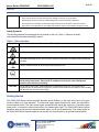
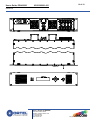
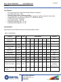
USER’S GUIDE, PONA 3000
UG-21069001-001
PONA 3000 Series
High Power EDFA
User’s Guide
For more information on this and other products:
Contact Sales at Ortel 626-293-3400, or visit www.ortel.com.
1 of 18
2 of 18
User’s Guide, PONA 3000
UG-21069001-001
Revision B
Table of Contents
Safety Information ............................................................................................................................3
Power Requirements........................................................................................................................3
Safety Instructions ...........................................................................................................................3
Before Initializing and Operating the Unit.........................................................................................3
Operating the Unit ............................................................................................................................3
Safety Symbols ................................................................................................................................4
Getting Started.................................................................................................................................4
Before Initializing and Operating the Unit.........................................................................................5
Note: Keep the packaging................................................................................................................5
Operating Environment ....................................................................................................................5
General Information and Specifications ...........................................................................................9
Key Features..................................................................................................................................11
Specifications .................................................................................................................................11
Physical..........................................................................................................................................12
Qualification ...................................................................................................................................13
PONA LED Alarms.........................................................................................................................13
Serial Port ......................................................................................................................................17
After powered up............................................................................................................................17
Ortel, a division of EMCORE
2015 West Chestnut Street
Alhambra, California 91803-1542
Tel: 626-293-3400
Fax: 626-293-3428
www.emcore.com
Copyright 2003. EMCORE Corporation
User’s Guide, PONA3000
3 of 18
UG-21069001-001
Revision B
Safety Information
Power Requirements
The system can operate from an AC power source that supplies 85 V AC to 265 V AC 50/60 Hz or a DC
power source that supplies -36 to -60 V DC..
Safety Instructions
The following safety instructions must be observed whenever the unit is operated, serviced, or repaired.
Failure to comply with any of these instructions or with any precaution or warning contained in the user’s
manual is in direct violation of the standards of design, manufacture, and intended use of the unit. ORTEL
assumes no liability for the customer’s failure to comply with any of these safety requirements.
Before Initializing and Operating the Unit
; Inspect the unit for any signs of damage, and read the user’s manual thoroughly.
; Install the unit as specified in the Getting Started section.
; Ensure that the unit and any devices or cords connected to it are properly grounded.
Operating the Unit
Warning
To avoid the risk of injury or death, always observe the following precautions before initializing the unit:
•
If using a voltage-reducing autotransformer to power the unit, ensure that the common terminal connects to
the earthed pole of the power source.
•
Use only the type of power cord supplied with the unit.
•
Connect the power cord only to a power outlet equipped with a protective earth contact. Never connect to an
extension cord that is not equipped with this feature.
•
Willfully interrupting the protective earth connection is prohibited.
•
Never look into the end of an optical cable connected to an optical output device that is operating. Laser
radiation is invisible, and direct exposure can severely injure the human eye. For more information, see the
user’s manual of the laser source in use.
•
Turning off the power to the device does not always block the externally supplied radiation to the connector at
the output of the unit.
•
Do not use the unit outdoors.
•
To prevent potential fire or shock hazard, do not expose the unit to any source of excessive moisture.
•
Do not operate the unit when its covers or panels have been removed.
•
Do not interrupt the protective earth grounding. Any such action can lead to a potential shock hazard that can
result in serious personal injury.
•
Do not operate the unit if an interruption to the protective grounding is suspected. In this case, ensure that the
unit remains inoperative.
•
Use only the type of fuse specified by the manufacturer as appropriate for this unit. Do not use repaired
fuses, and avoid any situations that can short-circuit the fuse.
•
Unless absolutely necessary, do not attempt to adjust or perform any maintenance or repair procedure when
the unit is opened and connected to a power source.
•
Repairs are to be carried out only by a qualified professional.
•
Do not attempt any adjustment, maintenance, or repair procedure to the unit’s internal mechanism if
Ortel, a division of EMCORE
2015 West Chestnut Street
Alhambra, California 91803-1542
Tel: 626-293-3400
Fax: 626-293-3428
www.emcore.com
Copyright 2003. EMCORE Corporation
User’s Guide, PONA3000
4 of 18
UG-21069001-001
Revision B
immediate first aid is not accessible.
•
Disconnect the power cord from the unit before adding or removing any components.
•
Operating the unit in the presence of flammable gases or fumes is extremely hazardous.
•
Do not perform any operating or maintenance procedure that is not described in the user’s manual.
•
Some of the unit’s capacitors can be charged even when the unit is not connected to the power source.
Safety Symbols
The following symbols and messages can be marked on the unit (Table 1). Observe all safety
instructions that are associated with a symbol.
Table 1: Safety Symbols
Symbol
Description
Laser safety. See the user’s manual for instructions on handling and operating the unit safely.
See the user’s manual for instructions on handling and operating the unit safely.
Electrostatic discharge (ESD). See the user’s manual for instructions on handling and operating the
unit safely.
Frame or chassis terminal for electrical grounding within the unit.
Protective conductor terminal for electrical grounding to the earth.
WARNING
The procedure can result in serious injury or loss of life if not carried out in proper compliance
with all safety instructions. Ensure that all conditions necessary for safe handling and
operation are met before proceeding.
CAUTION
The procedure can result in serious damage to or destruction of the unit if not carried out in
compliance with all instructions for proper use. Ensure that all conditions necessary for safe handling
and operation are met before proceeding.
Getting Started
The PONA 3000 Series Optical Amplifier provides optical isolation on the input and output of the gain
block for stable, low noise operation. The input and output optical signal power levels are detected for
monitoring and control. The input optical signal is amplified with active gain control for a constant output
power level, or with active output power control for constant gain mode. The PONA 3000 Series Optical
Amplifiers also provide monitors and associated alarms for all vital characteristics. The optical output of
the PONA 3000 Series Optical Amplifiers can be split into several ports by an optional internal splitter.
Ortel, a division of EMCORE
2015 West Chestnut Street
Alhambra, California 91803-1542
Tel: 626-293-3400
Fax: 626-293-3428
www.emcore.com
Copyright 2003. EMCORE Corporation
User’s Guide, PONA3000
5 of 18
UG-21069001-001
Revision B
The PONA 3000 Series includes: AC/DC Power Supply, Front Panel, Optical Splitters, network card, and
all necessary connectors.
Before Initializing and Operating the Unit
•
•
Inspect the unit for any signs of damage.
Read the user’s manual thoroughly, and become familiar with all safety symbols and instructions to
ensure that the unit is operated and maintained safely.
Initial Inspection
Warning
•
To avoid electrical shock, do not initialize or operate the unit if it bears any sign of damage to any
portion of its exterior surface, such as the outer cover or panels.
Check that the unit and contents are complete:
1. Wear an anti-static wrist strap and work in an electrostatic discharge (ESD) controlled area.
2. Inspect the shipping container for any indication of excessive shock to the contents, and inspect the
contents to ensure that the shipment is complete.
3. Inspect the unit for structural damage that can have occurred during shipping.
Note: Keep the packaging.
Immediately inform Ortel and, if necessary, the carrier if the contents of the shipment are incomplete, if
the unit or any of its components are damaged or defective, or if the unit does not pass the initial
inspection.
Operating Environment
In order for the unit to meet the warranted specifications, the operating environment must meet the
following conditions for temperature and humidity.
Temperature
The unit can be operated in the temperature range of -0 to 50ûC (standard) or -40 to 65°C for custom
orders.
Humidity
The unit can be operated in environments with up to 85% humidity, non-condensing (-40 to 85 °C). Do
not expose it to any environmental conditions or changes to environmental conditions that can cause
condensation to form inside the unit.
Ortel, a division of EMCORE
2015 West Chestnut Street
Alhambra, California 91803-1542
Tel: 626-293-3400
Fax: 626-293-3428
www.emcore.com
Copyright 2003. EMCORE Corporation
User’s Guide, PONA3000
6 of 18
UG-21069001-001
Revision B
Warning
•
Do not use the unit outdoors.
•
To prevent potential fire or shock hazard, do not expose the unit to any source of excessive
moisture.
Storing and Shipping
To maintain optimum operating reliability, do not store the unit in locations where the temperature falls
below -40ûC or rises above 85ûC. Avoid any environmental condition that can result in internal
condensation. Ensure that these temperature and humidity requirements can also be met whenever the
unit is shipped.
Claims and Repackaging
Immediately inform Ortel and, if necessary, the carrier, if
•
•
•
The contents of the shipment are incomplete
The unit or any of its components are damaged or defective
The unit does not pass the initial inspection
In the event of carrier responsibility, Ortel will allow for the repair or replacement of the unit while a claim
against the carrier is being processed.
Returning Shipments to Ortel
Ortel only accepts returns for which an approved Return Material Authorization (RMA) has been issued
by Ortel sales personnel. This number must be obtained prior to shipping any material to Ortel. The
owner’s name and address, the model number and full serial number of the unit, the RMA number, and
an itemized statement of claimed defects must be included with the return material.
Ship the return material in the original shipping container and packing material. If these are not available,
typical packaging guidelines are as follows:
1. Wear an anti-static wrist strap and work in an ESD controlled area.
2. Wrap the unit in anti-static packaging. Use anti-static connector covers, as applicable.
3. Pack the unit in a reliable shipping container.
4. Use enough shock-absorbing material (10 to 15 cm or 4 to 6 in on all sides) to cushion the unit and
prevent it from moving inside the container. Pink poly anti-static foam is recommended.
5. Seal the shipping container securely.
6. Clearly mark FRAGILE on its surface.
7. Always provide the model and serial number of the unit and, if necessary, the RMA number on any
accompanying documentation.
Ortel, a division of EMCORE
2015 West Chestnut Street
Alhambra, California 91803-1542
Tel: 626-293-3400
Fax: 626-293-3428
www.emcore.com
Copyright 2003. EMCORE Corporation
User’s Guide, PONA3000
7 of 18
UG-21069001-001
Revision B
8. Please contact the RMA department, using the contact information at the beginning of this document,
to provide an RMA number and a shipping address.
Unpacking
1. Inspect the shipping boxes for any obvious damage.
2. Unpack the unit from all packaging boxes.
3. Inspect the appearance of the unit for any shipping damage.
4. In case of damage, document and inform the shipping company and your local representative.
5. Save the shipping boxes and their inserts for any future reshipment for upgrade or repair.
NOTE: In the event of a reshipment back to the manufacturer, any additional damage caused by not using the
original boxes will be considered the responsibility of the customer.
PONA Mounting and Power Connection
1. Mount the unit into a 19-inch wide rack or cabinet.
2. Turn the unit power supply switch located on the rear panel off.
3. Turn the key switch located on the front panel to the OFF position.
4. AC powered models: Plug the power cord supplied with the Unit into the three-prong connector
on the rear panel and place the other end of the power cord into a 100-240 VAC, 50-60 Hz power
source (e.g. wall socket).
5. DC powered models: Slightly loosen the screws labeled -48V and -48V RTN. Place a wire
under the screw labeled “-48V RTN” and tighten the screw. Attach the opposite end of the
wire to a ground terminal on a -48V DC power supply (-36 to -60V). Place a wire under the
screw labeled”-48V” and tighten the screw. Attach the opposite end of the wire to a -48V
terminal on a -48V DC power supply. Turn on the DC power supply.
6. Turn the unit power switch to the ON position.
Optical Connections and Unit Verification
1. Clean all fiber patch cords before connecting.
Ortel, a division of EMCORE
2015 West Chestnut Street
Alhambra, California 91803-1542
Tel: 626-293-3400
Fax: 626-293-3428
www.emcore.com
Copyright 2003. EMCORE Corporation
User’s Guide, PONA3000
8 of 18
UG-21069001-001
Revision B
Cleaning Guidelines
Fiber Patch cord connectors
•
•
Remove the fiber connector dust cap and wipe the fiber connector tip with a dry lint-free cloth (such
as Kimwipes). Inspect for scratches or debris on connector surface by using a fiberscope.
If no scratches or debris are found the connector is now clean and ready for connection. If debris or
scratches are found then repeat the fiber patch cord connector cleaning guidelines.
Fiber Bulkhead connectors
•
Compressed air may be used to clean fiber bulkhead connectors. Use compressed air with at least
the following specifications:
• Non-residue, inert gas for precision dust removal
• Ultra-filtered to < 0.2 microns
• Recommended for optical systems
• Using compressed air as listed above, remove the bulkhead dust cover and hold the can of
compressed air about 6 inches from the connector. After spraying a few short bursts into the
bulkhead the connector is clean and ready for connection.
• If compressed air is not available, the PONA’s fiber bulkhead connector can be cleaned by 2.5
mm cotton swap or connector plate may be removed to clean the internal fiber patch cords.
Note: CAUTION: Use caution when handling fibers. Do not exceed fiber manufacturers
pulling tension or bend radius specifications when removing fiber bulkhead connector
plate.
•
To remove the PONA optical connector plate, remove the screw on the far left of the optical plate
and remove the screw on the far right of the optical plate. Do not remove the screws on the
optical bulkhead connector.
• Slowly remove the optical connector plate from the rear panel and disconnect each fiber
connector from the bulkhead mounted on the plate
• Clean each fiber connector.
2. Make sure the laser key switch on the front panel is in the OFF position.
3. Connect a fiber patch cord from the output of the transmitter to an optical power meter.
4. Turn the transmitter laser key switch to the ON position and use a serial port connection to make
sure the parameters are set for proper operation.
7. Using the optical power meter verify the transmitter optical power is within specification.
6. Turn the transmitter laser key switch to the OFF position.
7. Remove the optical patch cord from the power meter and plug the patch cord input optical connector.
8. Connect a patch cord from the output to an optical power meter.
9. Turn the laser key switches on the transmitter and PONA front panel to the ON position.
Note: Using the optical power meter verify the optical output of the PONA is within specification.
Note:Note: Difference in patch cords may result in slightly different optical power measurements.
10. Turn off the key switch.
Ortel, a division of EMCORE
2015 West Chestnut Street
Alhambra, California 91803-1542
Tel: 626-293-3400
Fax: 626-293-3428
www.emcore.com
Copyright 2003. EMCORE Corporation
User’s Guide, PONA3000
UG-21069001-001
9 of 18
Revision B
11. Remove the patch cord from the optical power meter and plug the patch cord into the fiber for the link
being deployed.
12. Turn the key switch to the ON position.
General Information and Specifications
The Ortel PONA 3000 Series Fiber Optical Amplifier Module is an ideal building block for OEM system
integrators. The family of PONA 3000 Optical Amplifiers is designed to meet the most demanding noise
performance requirements of CATV and FTTx applications, and performs all functions required of an
optical amplifier for system integration. PONA 3000 Series Optical Amplifiers provide optical isolation on
the input and output of the gain block for stable, low noise operation. The input and output optical signal
power levels are detected for monitoring and control. The input optical signal is amplified with active gain
control for a constant output power level, or with active output power control for constant gain mode. The
PONA 3000 Series Optical Amplifiers also provide monitors and associated alarms for all vital
characteristics. The optical output of the PONA 3000 Series Optical Amplifiers can be split into several
ports by an optional internal splitter.
The PONA 3000 Series includes: AC/DC Power Supply, Front Panel, Optical Splitters, network card, and
all necessary connectors.
PONA 3000 Series Fiber Optical Amplifier Module.
shows the PONA 3000 Series Fiber Optical Amplifier Module.
Figure iv - 1: PONA 3000 Series Fiber Optical Amplifier Module.
Ortel, a division of EMCORE
2015 West Chestnut Street
Alhambra, California 91803-1542
Tel: 626-293-3400
Fax: 626-293-3428
www.emcore.com
Copyright 2003. EMCORE Corporation
User’s Guide, PONA3000
UG-21069001-001
10 of 18
Revision B
Ortel, a division of EMCORE
2015 West Chestnut Street
Alhambra, California 91803-1542
Tel: 626-293-3400
Fax: 626-293-3428
www.emcore.com
Copyright 2003. EMCORE Corporation
User’s Guide, PONA3000
11 of 18
UG-21069001-001
Revision B
Key Features
•
•
•
•
•
•
•
•
•
Full Function High Power Fiber Optic Amplifier Ready for Integration
Low Noise Figure (Typ < 6 dB)
Total Input Power Range: -10 dBm to +12 dBm
Total Output Power: +27 dBm to +35 dBm (optical output power splitter is optional for these units)
Standard RS-232 Communications (RS-485, I2C, or SNMP are optional)
Low Electrical Power Consumption
Input/Output Isolation > 40/40 dB
Polarization Dependant Gain < 0.1 dB
Polarization Mode Dispersion < 0.5 ps
Specifications
Specifications for the PONA 3000 Series Fiber Optical Amplifier Module.
Table iv-1: Specifications
Property
Symbol
Limit
Product Code
PONA Models
3027
3030
3032
3033
Comment
3035
3037
Performance
note 1
Operating Input Power
Pin (dBm)
Max
+12
+12
+12
+12
+12
+12
Operating Output
Power
Pin (dBm)
Min
-10
-10
-10
-10
-10
-10
Output Power
Po (dBm)
27.0
30.0
32.0
33.0
35.0
37.0
Noise Figure
NF (dB)
Typ/Max
Static Gain Flatness
GF (dB)
Dynamic Gain Flatness
Output Power Stability
Power Consumption
Remnant pump power
to output
Nominal (note 2)
5.5/6.0 5.5/6.0 5.5/6.0 5.5/6.0 5.5/6.0 5.5/6.0
note 3
Max
+/-2.0
+/-2.0
note 4
(dB)
Max
+/-2.50 +/-2.50 +/-2.50 +/-2.50 +/-3.00 +/-3.00
note 5
(dB)
Max
+/-0.2
+/-0.2
+/-0.2
+/-0.2
+/-.02
+/-0.2
note 6
20
35
45
55
65
70
15
20
25
30
40
45
50 C Case
(Premium)
50 C Case
(Economy) note 7
<-30
<-30
<-30
<-30
<-30
<-30
Psys (W)
+/-2.0
+/-2.0
+/-2.0
+/-2.0
Max
Prp (dBm) Nom
Ortel, a division of EMCORE
2015 West Chestnut Street
Alhambra, California 91803-1542
Tel: 626-293-3400
Fax: 626-293-3428
www.emcore.com
Copyright 2003. EMCORE Corporation
User’s Guide, PONA3000
12 of 18
UG-21069001-001
Revision B
Notes
1.
2.
3.
4.
5.
6.
7.
Unless stated otherwise, all specifications apply over the full temperature range and humidity.
Depending on the fibre optic patchcord interface,t he measured value can vary up to 0.5 dB less than the actual value (measured before
splitters).
o
Measured @ 25 C and λ = 1557 nm, ∑ Pin = 0 dBm
o
Measured with a swept Probe Signal (Pp), where Pp = 0 dBm @ 25 C.
o
Measured with a swept Probe Signal (Pp), and a fixed Tone Signal (Pt) @ 1557 nm; (Pt =Pp+20 dB; Pt+Pp = 0 dBm) @ 25 C
Stability over polarization and temperature.
Premium version - PONA with cooled, Telecordia qualified pumps
Economy version - PONA with uncooled pumps
Physical
Physical Parameters shows the Physical Parameters.
Table iv-2: Physical Parameters
General Property
Requirement
Comments
Operating Wavelength
1545 ~ 1562 nm
Standard
Operating Case
Temperature
0o C to 50o C
-40o C to 65o C
Standard
Custom (available by special order)
Storage Temperature
-40o C to 85o C
Standard
Operating Humidity
20% to 85%
Non-condensing
Voltage Supply Range
85 VAC to 265 VAC 50/60 Hz
AC version
-36 to -60 V DC
DC version
Redundant power supply is available for the
2U configuration by PONA 3000 by customer
request
Optical Connectors
See ordering information
User specified
Dimensions in inches
19.0”W X 14.76”D X 1.72:”H
19” Rack Mounted, IU
19.0”W X 14.76”D X 3.44:”H
2U (optional, depending on customer request
for the number of optical output ports and
redundant power supply).
Ortel, a division of EMCORE
2015 West Chestnut Street
Alhambra, California 91803-1542
Tel: 626-293-3400
Fax: 626-293-3428
www.emcore.com
Copyright 2003. EMCORE Corporation
User’s Guide, PONA3000
13 of 18
UG-21069001-001
Revision B
Qualification
•
•
•
•
•
•
•
•
FCC: Subpart B. Part 15, class "A" Unintentional Radiators
CE: EN50083-2, 19995 with Amendment 1, which incorporates EN 55013 Radiated and
Conducted Emissions
EN 61000-4-3 Radiated Immunity
EN 55020
Conducted Immunity
EN 61000-3-2 Harmonics
All components meet Telecordia GR-1312 and GR-486 standards (Except pumps in Economy
Class).
EN 61000-3-2 Harmonics
Fit Rate: 90% level of confidence < 2000 @ 30oC Premium PONA 3037
90% level of confidence < 3500 @ 30oC Economy PONA 3037
PONA LED Alarms
Table 1-1 shows the PONA controls and indicators
Table 1-1: PONA Controls and Indicators
Item
1
Label
Alarm
Function
Green (no alarm) - indicates that adequate optical input power and output
power are present
Flashing Green (waiting temp) - indicates the pump is waiting for the laser
temperature to stabilize
OFF (configured OFF) - indicates the pump mode parameter is in OFF mode
(rather than constant current or power)
Steady Yellow (minor alarm) - indicates that one or more parameters is near an
operational limit without affecting the operation of the unit. Also, it can indicate
the key switch is in the OFF position.
Flashing Yellow (no alarms) – indicates that the laser currents fluctuates to
maintain the Constant Power Mode of the PONA
Red (major alarm) - indicates that one or more parameters is outside an
operational limit, which can affect the operation of the PONA
2
Laser Key
Switch
ON - indicates pump is enabled and can provide optical amplification. The LED
remains yellow indicating the pump is in a steady state (otherwise, it can
indicate the pump is dead)
OFF - indicates pump is OFF. The yellow LED is not lit.
Ortel, a division of EMCORE
2015 West Chestnut Street
Alhambra, California 91803-1542
Tel: 626-293-3400
Fax: 626-293-3428
www.emcore.com
Copyright 2003. EMCORE Corporation
User’s Guide, PONA3000
14 of 18
UG-21069001-001
Revision B
3
Display/Next
Push this button to change the LCD to the next display mode. If there is a
current alarm, this button cycles to the next of the currently active alarms. Any
new arriving alarms always cause the display to change. If there are no
pending alarms, the next key allows cycling through the following live-updating
data:
• Laser cur - shows the laser current in mA.
• bk facet - shows the back facet current in uA.
• TEC cur - shows the TEC current in mA.
• las temp - shows the temperature of the laser in degrees C
• Unit temp - shows the temperature of the pump case in degrees C.
• Out power - shows the composite output optical power in dBm
• Descriptor - shows the 16 character configured descriptor (the name of
the unit).
• Serial number - shows the 16 character factory set serial number.
Start up messages and the revision level of the firmware in the unit is shown as
the unit powers up.
4
Display Adjust
When there are no alarms and the display is showing constant cur, the UP and DOWN
arrows raise or lower the laser current output in the increments of 1mA. Adjustments,
which would directly trigger alarms or cause laser current to exceed configured limits,
are not allowed.
RESET returns the either the constant power or constant current setting back to the
factory-preset level.
5
(none)
LCD that displays status information. Can be used with Display/Next button.
6
Optical
Connection locations for the input fiber and out fiber with the proper type of optical
connector (FC/APC, SC/APC, or E2000/APC) for the purchased model.
7
Serial Port
Reserved for factory diagnostics. Do not use without consulting technical support.
8
1/0
On/Off switch for AC powered units. Allows the unit to be fully shut off (that is no
electrical power entry).
9
Input Power
IEC AC power plug with in-line fuse holder for connection to a standard three-prong UL
approved power plug.
10
Ground
PONA chassis ground lug. Should be attached to chassis ground of DC-48V power
supply.
11
Input Power
Input power connections for -48V DC input.
12
1/0
On/Off switch for DC powered units. Allows the unti to be fully shut off (that is, no
electrical power entry)
13
Fuse 2A
Fuse holder for -48V DC units. Push holder in and turn 1/4 turn to the left to release
fuse.
Ortel, a division of EMCORE
2015 West Chestnut Street
Alhambra, California 91803-1542
Tel: 626-293-3400
Fax: 626-293-3428
www.emcore.com
Copyright 2003. EMCORE Corporation
User’s Guide, PONA3000
15 of 18
UG-21069001-001
Revision B
Table 1-2 shows the alarms and descriptions:
Table 1-2: Alarms and descriptions
Alarm
Description
Laser Temp Hi
Alarm or warning for hi limit
Laser Temp Low
Alarm or warning for low limit
Laser Current Hi
Alarm or warning for high limit
Laser Current Lo
Alarm or warning for low limit
Unit Temp Hi
Alarm or warning for high limit
Unit Temp Hi
Alarm or warning for lo limit
+5 Volt H Alarm
A fixed value alarm set at 5.5 volts (no warning)
+5 Volt Lo Alarm
A fixed value alarm set at 4.5 volts (no warning)
Opt In Pwr Hi
Alarm or warning for high limit
Opt In Pwr Lo
Alarm or warning for low limit.
The pump shuts off during any time the input optical power is found to be below the low alarm
limit.
Opt Out Pwr Hi
Alarm or warning for high limit
Opt Out Pwr Lo
Alarm or warning for low limit
3V Pwr Bad
There is no settable parameter for this error condition. The alarm occurs when the
internal 3.3 volt power is read as either more than 0.1 volt too high or too low
Keyswitch Off
The keyswitch is found in the off position. This alarm causes the pump to shut down
1.1. Serial Reporting of Alarms
The PONA serial port is used to give the user information about the status of PONA. Among this
information are live updates as alarms occur or if they all go away. Status information can spontaneously
appear at power up and other times. The serial port uses full duplex RS 232 at 19200 BAUD, 2 stop bits,
one start bit and no parity. There is no protocol and all inbound and outbound messages are viewable
ASCII meant at a human rate of transfer. Each time a new alarm is found to occur, the following
message format is sent:
There is a start of line prompt character (either of $?>#) followed by a space either the string ALARM:
followed by one space OR the string WARN: followed by two spaces - a 32 characters, space padded
right justified string describing the alarm. The following are potential strings that can be sent out for
different alarm conditions:
Ortel, a division of EMCORE
2015 West Chestnut Street
Alhambra, California 91803-1542
Tel: 626-293-3400
Fax: 626-293-3428
www.emcore.com
Copyright 2003. EMCORE Corporation
User’s Guide, PONA3000
16 of 18
UG-21069001-001
Revision B
Laser 1 Temp Hi, Laser 1 Temp Low, Laser 1 Cur Hi, Laser 1 Current Low, Laser 2 Temp Hi, Laser
2 Temp Low, Laser 2 Cur Hi, Laser 2, Laser 3 Temp Hi, Laser 3 Temp Low, Laser 3 Cur Hi, Laser
3 Current Low, Unit Temp Hi, Unit Temp Low, +5 Volt HI, +5 Voltage In LO, Opt In Pwr HI,
Optical Power Input LO, Optical Power Output HI, Optical Power Output LO, 3v Pwr out of range,
Keyswitch OFF.
The string "value:" appears followed by a right justified 6-character rendering of the current value that
triggered the alarm event. The string "limits:" appears following by the related alarm and warning limited
right justified to 6 characters each and separated by a comma, and the entire alarm message is
terminated by a carriage return sequence”.
The following are some examples of alarm occurrences reported:
•
ALARM: Unit Temp Low
•
ALARM: Keyswitch OFF
•
WARN: Laser Temp Hi
value:-21.34 limits: -15.00, -20.00
value: 26.32 limits: 26.50, 27.00
Note:Alarms early on soon after start up can usually be ignored.
The string "last Alarm or Warning went away” appears when the final alarm present has gone away.
The only way to know which alarms are current at any point in time is to send the serial interface the
character’s’. This generates a list of current alarms followed by a line of pump state status.
Similarly, the PONA serial port is used to give the user information about the PONA settings.
Ortel, a division of EMCORE
2015 West Chestnut Street
Alhambra, California 91803-1542
Tel: 626-293-3400
Fax: 626-293-3428
www.emcore.com
Copyright 2003. EMCORE Corporation
User’s Guide, PONA3000
UG-21069001-001
17 of 18
Revision B
Serial Port
After powered up:
After the PONA has been powered up, the following is sent to the serial port of the PONA:
Enter Parameter number - or hit ? for list: e
1 Descriptor
PONA 3035
2 Part number
Eng. Demo
3 PmpCur Setpt 1 mA 220.00
4 PmpCur Setpt 2 mA 3450.00
5 PmpCur Setpt 3 mA 3450.00
6 PmpCur Setpt 4 mA 3000.00
7 PmpCur Setpt 5 mA 3000.00
8 PmpCur Setpt 6 mA 3000.00
9 PmpCur Hi Lim 1 mA 360.00
10 PmpCur Hi Lim 2 mA 3500.00
11 PmpCur Hi Lim 3 mA 3500.00
12 PmpCur Hi Lim 4 mA 3500.00
13 PmpCur Hi Lim 5 mA 3500.00
14 PmpCur Hi Lim 6 mA 3500.00
15 EDFA Pwr Setpt dBM
20.00
16 EDFA Pwr deadB dBM
0.05
17 PmpTem Setpt
C
25.00
18 PmpTem tolerance C
0.50
19 PmpTem Hi Lim
C
27.00
20 PmpTem Lo Lim
C
23.00
21 Pump1 Control mode CONST CUR 22 Pump2 Control mode CONST CUR
23 Pump3 Control mode CONST CUR 24 Pump4 Control mode CONST PWR
25 Pump5 Control mode CONST PWR 26 Pump6 Control mode CONST PWR
27 Pmp1 Cur Hi MAJ mA 360.00
28 Pmp1 Cur Hi MIN mA 350.00
29 Pmp1 Cur Lo MIN mA
15.00
30 Pmp1 Cur Lo MAJ mA
5.00
31 Pmp2 Cur Hi MAJ mA 3500.00
32 Pmp2 Cur Hi MIN mA 3500.00
33 Pmp2 Cur Lo MIN mA
0.00
34 Pmp2 Cur Lo MAJ mA
0.00
35 Pmp3 Cur Hi MAJ mA 3500.00
36 Pmp3 Cur Hi MIN mA 3500.00
37 Pmp3 Cur Lo MIN mA
0.00
38 Pmp3 Cur Lo MAJ mA
0.00
39 Pmp4 Cur Hi MAJ mA 3500.00
40 Pmp4 Cur Hi MIN mA 3500.00
41 Pmp4 Cur Lo MIN mA
0.00
42 Pmp4 Cur Lo MAJ mA
0.00
43 Pmp5 Cur Hi MAJ mA 3500.00
44 Pmp5 Cur Hi MIN mA 3500.00
45 Pmp5 Cur Lo MIN mA
0.00
46 Pmp5 Cur Lo MAJ mA
0.00
47 Pmp6 Cur Hi MAJ mA 3500.00
48 Pmp6 Cur Hi MIN mA 3500.00
49 Pmp6 Cur Lo MIN mA
0.00
50 Pmp6 Cur Lo MAJ mA
0.00
51 I TEC 1 Hi MAJ mA 1000.00
52 I TEC 2 Hi MAJ mA 2500.00
53 I TEC 3 Hi MAJ mA 2500.00
54 I TEC 4 Hi MAJ mA 2500.00
55 I TEC 5 Hi MAJ mA 2500.00
56 I TEC 6 Hi MAJ mA 2500.00
57 Pump Tem Hi MAJ C
27.00
58 Pump Tem Hi MIN C
26.50
59 Pump Tem Lo MIN C
23.50
60 Pump Tem Lo MAJ C
23.00
61 InPwr Hi MAJ dBM
12.20
62 InPwr Hi MIN dBM
12.10
63 InPwr Lo MIN dBM -10.10
64 InPwr Lo MAJ dBM -10.20
65 OutPwr Hi MAJ dBM
21.00
66 OutPwr Hi MIN dBM
20.80
67 OutPwr Lo MIN dBM
18.20
68 OutPwr Lo MAJ dBM
18.00
69 UnitTem Hi MAJ
C
60.00
70 UnitTem Hi MIN
C
58.00
71 UnitTem Lo MIN
C
5.00
72 UnitTem Lo MAJ
C
0.00
73 InPwr Coef A
0.26
74 InPwr Coef B
0.14
75 InPwr Coef C
10.01
76 InPwr Coef D
6.99
77 OutPwr Coef A
-0.04
78 OutPwr Coef B
-0.12
79 OutPwr Coef C
3.19
80 OutPwr Coef D
12.40
81 Pump 1 Out Zero
-0.08
82 Pump 1 Out Span
1.06
83 Temp 1 Out Zero
-0.10
84 Temp 1 Out Span
1.06
85 Pump 2 Out Zero
-0.07
86 Pump 2 Out Span
1.05
87 Temp 2 Out Zero
-0.10
88 Temp 2 Out Span
1.05
89 Pump 3 Out Zero
-0.06
90 Pump 3 Out Span
1.04
91 Temp 3 Out Zero
-0.11
92 Temp 3 Out Span
1.06
93 Pump 4 Out Zero
-0.08
94 Pump 4 Out Span
1.06
Ortel, a division of EMCORE
2015 West Chestnut Street
Alhambra, California 91803-1542
Tel: 626-293-3400
Fax: 626-293-3428
www.emcore.com
Copyright 2003. EMCORE Corporation
User’s Guide, PONA3000
18 of 18
UG-21069001-001
Revision B
95 Temp 4 Out Zero
97 Pump 5 Out Zero
99 Temp 5 Out Zero
101 Pump 6 Out Zero
103 Temp 6 Out Zero
105 # up steps for pwr
107 All pumps control
-0.11
-0.06
-0.09
-0.07
-0.11
9.00
ON
96 Temp 4 Out Span
98 Pump 5 Out Span
100 Temp 5 Out Span
102 Pump 6 Out Span
104 Temp 6 Out Span
106 Gain Setpoint1 dBM
108 Delay befor pumpOn
1.05
1.06
1.05
1.06
1.06
1
9
When the PONA receives the character "a" - the information similar to the following about read values
will be sent out to the PONA serial port:
# a
laser1cur
laser2cur
laser3cur
laser4cur
laser5cur
laser6cur
bk facet1
bk facet2
bk facet3
bk facet4
bk facet5
bk facet6
TEC 1 cur
TEC 2 cur
TEC 3 cur
TEC 4 cur
TEC 5 cur
TEC 6 cur
las1 temp
las2 temp
las3 temp
las4 temp
las5 temp
las6 temp
unit temp
in power
out pwr
ref 2.5v
229.492 mA
3100.586 mA
3111.572 mA
1665.039 mA
1701.660 mA
1669.922 mA
800.781 uA
179.443 uA
323.486 uA
86.670 uA
118.408 uA
180.664 uA
122.070 mA
947.266 mA
722.656 mA
344.238 mA
427.246 mA
373.535 mA
25.160 degC
25.116 degC
25.008 degC
25.464 degC
24.791 degC
25.029 degC
32.746 degC
1.583 dBm
20.041 dBm
2.482 Volts
Ortel, a division of EMCORE
2015 West Chestnut Street
Alhambra, California 91803-1542
Tel: 626-293-3400
Fax: 626-293-3428
www.emcore.com
Copyright 2003. EMCORE Corporation